1
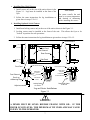
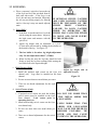
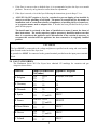
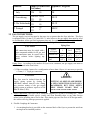
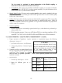
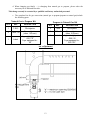
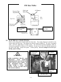
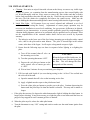
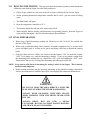
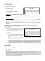
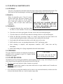
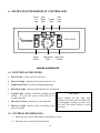
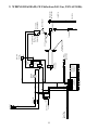
24G Series Flatbottom Gas Fryers (CE)
Installation, Operation & Maintenance Manual
CE ONLY
Frymaster, a member of the Commercial Food Equipment Service Association, recommends
using CFESA Certified Technicians.
24-Hour Service Hotline 1-800-551-8633
Price: $6.00
819-5727
11-99
FLATBOTTOM GAS FRYER
Series 24G (CE)
TABLE OF CONTENTS
1.
2.
3.
4.
5.
6.
7.
8.
9.
FACTORY SERVICE AND PARTS ORDERING
IMPORTANT INFORMATION
INSTALLATION
OPERATION
CLEANING AND MAINTENANCE
SOLID STATE THERMOSTAT CONTROLLER
TROUBLESHOOTING
PARTS LIST
WIRING DIAGRAM
1. FACTORY SERVICE & PARTS ORDERING
1.1 ORDERING PARTS:
Customers may order parts directly from their
local Authorized Parts Distributor. For this
address and phone number, contact your
Maintenance & Repair Center or call the
factory. The factory address and phone number
are on the cover of this manual.
To speed up your order, the following
information is required:
Ordering Parts
Model Number
Type
Serial Number
Type of Gas
Optional Equipment
Item Part Number
Quantity Needed
Service Information
Model Number
Type
Serial Number
Type of Gas
Optional Equipment
Nature of Problem
1.2 SERVICE INFORMATION:
Call the Frymaster Service Hotline number on
the cover of this manual or 1-318-865-1711 for
the location of your nearest Maintenance &
Repair Center. Always give the model and serial
numbers of your filter and fryer.
To assist you more efficiently, follow the
Service Information chart when calling for
service information. Also provide any other
information which may be helpful in solving
your service problem.
After Sales
Servicer
Address
Telephone/Fax
Model #
Serial #
Type of Gas:
1.3 AFTER SALES:
In order to improve service, have the After
Sales chart filled in by the Frymaster
Authorized Servicer who installed this
equipment.
Fryer Equipped For:
2
PAGE
2
3
6
17
18
19
21
23
25
2. IMPORTANT INFORMATION
2.1 DESCRIPTION:
The Frymaster Flatbottom Series 24G Fryers are energy-efficient, gas-fired units, design-certified
by the International Approval Services (AGA/CGA), AFNOR, NSF International and
manufactured to their basic performance and application specifications.
All units are shipped completely assembled with accessories packed inside the frypot. All units
are adjusted, tested and inspected at the factory before shipment. Sizes, weights and input rates of
all models are listed in this manual.
NOTE: The on-site supervisor is responsible for ensuring that operators are made aware of inherent
dangers of operating a deep fat fryer, particularly aspects of oil filtration, draining, and
cleaning of the fryer.
2.2 PRINCIPLE OF OPERATON:
A reliable draft inducer is used to draw air over the burners for combustion. This air movement
directs the combustion products back and forth across the underside of the flatbottom vessel by
means of a set of baffles, transferring heat to every area evenly. Since the draft inducer operates
only during the combustion cycle, all cold air is prevented from entering the combustion chamber
and cooling the oil during the coasting cycle.
2.3 RATING PLATE:
This is attached to the inside right-hand corner of the front door panel. Information provided
includes the model and serial number of the fryer, kW (BTU/hr) input of the burners, outlet gas
pressure in mbar (inches WC) and whether the unit has natural or propane gas orifices.
CAUTION
DANGER!
THE FRYER MUST BE CONNECTED
ONLY TO THE TYPE OF GAS IDENTIFIED
ON THE ATTACHED RATING PLATE.
Local building codes usually prohibit a
fryer with its open tank of hot oil form
being installed beside an open flame of
any type, whether a broiler or open
burner of a range.
2.4 PRE-INSTALLATION:
a. GENERAL: Only a licensed plumber should install any gas-fired equipment.
1. A manual gas shut-off valve must be installed in the gas supply line ahead of the fryer(s)
for safety and ease of future service.
2. The Flatbottom Series 24G gas fryers require 230 volts AC and are equipped with a 16-3
SJT grounded flexible power cord for a direct connection to a 230 VAC power supply.
Amperage draw for each unit depends on the accessories supplied with the unit. See
detailed instructions packaged with the fryer line-up.
3
b. CLEARANCES: The fryer area must be kept free and clear of all combustibles. This unit is
design-certified for the following installations:
1. Other than household use.
2. Non-combustible floor installation equipped with factory-supplied 15 cm (6 inch)
adjustable legs or 13 cm (5 inch) casters.
3. Combustible construction with a minimum clearance of 15 cm (6 inches) side and 15 cm
(6 inches) rear, and equipped with factory-supplied 15 cm (6 inch) adjustable legs or 13 cm
(5 inch) casters.
2.5 AIR SUPPLY & VENTILATION:
Keep the area around the fryer clear to prevent obstruction of combustion and ventilation air flow
as well as for service and maintenance.
a. Do not connect this fryer to an exhaust duct.
b. A proper installation and adjustment will ensure adequate air flow to the fryer system
which input is 2m3 per hour per kW for gas supplied.
c. A commercial, heavy-duty fryer must vent its combustion wastes to the outside of the building.
It is essential that a deep fat fryer be set under a powered exhaust hood or that an exhaust fan
be provided in the wall above the unit, as exhaust gas temperatures are approximately 427 538°C (800 - 1000°F). Check air movement during installation. Strong exhaust fans in this
hood or in the overall air conditioning system can produce slight air drafts in the room.
d. Do not place the fryer’s flue outlet directly into the plenum of the hood, as it will affect the gas
combustion of the fryer.
e. Never use the interior of the fryer cabinet for storage or store items on shelving over or behind
the fryer. Exhaust temperatures can exceed 427°C (800°F) and may damage or melt items
stored in or near the fryer.
f. Adequate distance must be maintained from the flue outlet of the fryer(s) to the lower edge of
the filter bank. A minimum of 45 cm (17.75 inches) should be maintained between the flue(s)
and the lower edge of the exhaust hood filter.
g. Filters and drip troughs should be part of any industrial hood, but consult local codes before
constructing and installing any hood. The duct system, the exhaust hood and the filter bank
must be cleaned on a regular basis and kept free of grease.
2.6 ALTITUDE:
The fryer input rating kW (BTU/hr) is for elevations up to 610 m (2000 feet). For elevations
above 610 m (2000 feet), the rating should be reduced four percent (4%) for each additional 305
meters (1000 feet) above sea level.
The correct orifices are installed at the factory if operating altitude is known at time of the
customer’s order.
4
2.7 RECEIVING AND UNPACKING:
Check that the container is upright. Unpack the fryer carefully and remove all accessories from
the carton. Do not discard or misplace these, as they will be needed.
After unpacking, immediately check the equipment for visible signs of shipping damage. If such
damage has occurred, contact the carrier and file the appropriate freight claims. Do not contact
the factory, as the responsibility of shipping damage is between the carrier and the dealer or enduser.
If your equipment arrives damaged:
a. File claim for damages immediately – Regardless of extent of damage.
b. Visible loss or damage – Be sure this is noted on the freight bill or express receipt and is
signed by the person making the delivery.
c. Concealed loss or damage – If damage is unnoticed until equipment is unpacked, notify the
freight company or carrier immediately, and file a concealed damage claim. This should be
done within fifteen (15) days of date of delivery. Be sure to retain container for inspection.
NOTE: Frymaster does not assume responsibility for damage or loss incurred in transit.
2.8 CONVERSION OF UNITS:
Pressure:
1 mbar = 10.2 mm water column (mm WC) = 0.4 Inch WC
20 mbar = 204 mm WC = 8 Inch WC
1 Inch WC = 25.4 mm WC = 2.5 mbar
Heat Input:
1 kW = 3410 BTU/hr
100 BTU/hr = 0.293 kW
Temperature:
0° Celsius = 32° Fahrenheit
Temp. in degree Celsius = (Temperature in degree Fahrenheit (F) – 32) X 0.555
100° Celsius = (212° Fahrenheit – 32) X 0.555
5
3. INSTALLATION
3.1 POSITIONING:
a. Initial Installation: If installed with legs, do not push against any unit edges to adjust its
position. Use a pallet or lift jack to lift it slightly and place it where it is to be installed.
b. Relocating The Fryer: If relocating a fryer installed with legs, remove all weight from each
leg before moving.
Note:
If a leg becomes damaged during movement, contact your service agent for immediate
repair/replacement of that leg.
DANGER!
THIS FRYER MAY TIP AND CAUSE PERSONAL INJURY IF NOT
SECURED CORRECTLY IN A STATIONARY POSITION. REMOVE
ALL SHORTENING BEFORE MOVING FRYER AS IT MAY CAUSE
SEVERE BURNS UPON CONTACT.
3.2 LEG AND CASTER INSTALLATION:
a. General:
1. Install legs and rear rigid casters near where the fryer is to be used, as neither are secure
for long transit. Unit cannot be curb mounted and must be equipped with the legs and rear
rigid casters provided.
2. When positioning the fryer, gently lower the fryer into position to prevent undue strain to
the legs and internal mounting hardware. Use a pallet or lift jack to lift and position the
fryer if possible. Tilting the fryer may damage the legs.
3. The rigid casters must be installed on the fryer rear channel assembly only.
4. Proceed to Step 3.3, Leveling, after legs and rear rigid casters are installed to ensure the
fryer is level before using.
b. Leg Installation:
1. Remove unit from pallet.
2. Carefully raise unit with forklift, pallet jack, or other steady means.
3. Place one lock washer on each hex head screw.
4. Insert hex head screws with lock washers (1/4-20 threads by ¾" (19 mm) long) through
bolt holes of leg mounting plates as shown in the Figure 3-1 on the next page. A locknut
has been attached to the top side of the mounting plate at the factory to capture the hex
head screw as it is screwed in.
5. Tighten the bolts and nuts with each bolt to 5.65 joules (50 inch-lbs.) minimum torque.
6
c. Installing Rear Rigid Casters:
1. Install casters only at the rear of the unit as shown in the
Figure 3-1. Legs must be installed at the front of the
fryer.
2. Follow the same instructions for leg installations as
given above in steps 3.2.b.1-5.
CAUTION
For caster retrofit, the unit
must be at room temperature
and drained of shortening
before installing the casters.
d. Installing Optional Swivel Casters:
1. Install non-locking casters only at the rear of the unit as shown in the Figure 3-1.
2. Locking casters must be installed at the front of the unit. This allows the fryer to be
"locked" in position for safe operations.
3. Follow the same instructions for leg installations as given above in steps 3.2.b.1-5.
Structural Back
Side Panel
Front Channel
Rear Channel
Side Panel
1/4-20 HX HD Lock Nut
Front Door
1/4-20 HX HD Lock Nut
Caster Shims
if required.
Caster Shims
if required.
Front Channel
Front Leg
w/Mounting Plate
Adjust as needed.
Lock Washer
Lock Washer
1/4-20 HX HD Screw
1/4-20 HX HD
Screw
Rear Rigid Caster
13 cm/5 in
Locking Caster
13 cm/5 in
Leg and Caster Installations
Figure 3-1
WARNING!
A FRYER MUST BE LEVEL BEFORE FILLING WITH OIL. IF THE
FRYER IS NOT LEVEL, THE FRYER MAY TIP OVER AND MAY CAUSE
INJURY TO THE OPERATOR.
7
3.3 LEVELING:
a. Place a carpenter’s spirit level across the top
of the fryer and level the unit both front-toback and side-to-side. If the fryer is not
level, the unit may not function efficiently,
the oil may not drain properly for filtering
and in a line-up it may not match adjacent
units.
b. Legs (Only):
1. If the floor is smooth and level, level the
unit by using the caster shims. Adjust to
the high corner and measure with the
spirit level.
WARNING!
IF OPTIONAL SWIVEL CASTERS
ARE USED, LOCKING CASTERS
MUST BE INSTALLED ON THE
FRYER
FRONT
CHANNEL.
FAILURE TO LOCK CASTERS
PRIOR TO OPERATING THE
FRYER MAY CAUSE THE FRYER
TO MOVE AND CAUSE INJURY
TO THE OPERATOR.
2. Adjust leg height with an adjustable or 1-1/16”
(27mm) open end wrench by turning the hex bullet on
the bottom of the leg. See figure 3-2 .
3. The hex bullet is for minor leg height adjustment
only. Do not adjust more than 1" (22mm).
4. When leveling the unit, the leg body should be held
firmly to keep the leg from rotating while turning the
hex bullet foot to the required height.
c. Rigid Casters (Only):
1. Install the optional rigid casters on the fryer rear
channel only. Legs must be installed on the front
channel.
Adjust leg height with an
adjustable wrench.
Figure 3-2
2. Do not use more than two metal shims per caster.
3. There are no thread adjustments for the rigid
casters.
d. Swivel Casters (Only):
WARNING!
1. If optional swivel casters are used, the locking
swivel casters must be installed on the fryer
front channel.
Lock casters prior to
operating the fryer.
2. Install non-locking swivel casters on the fryer
rear channel only.
3. Do not use more than two metal shims per
caster.
4. There are no thread adjustments for the swivel
casters.
8
DO NOT USE MORE THAN
TWO METAL SHIMS PER
LEG/CASTER.
USING MORE THAN TWO
SHIMS PER LEG/CASTER
MAY CAUSE THE FRYER TO
BECOME UNSTABLE, TIP
OVER, AND MAY CAUSE
INJURY TO THE OPERATOR.
e. If the floor is uneven or has a decided slope, it is recommended to place the fryer on a smooth
platform. Do not rely on leg thread or caster shims for adjustments.
f. If the fryer is moved, re-level the fryer following the instructions given in Steps 3.3.a-c.
g. ANSI Z83.11a-1997 requires a fryer be restrained to prevent tipping when installed in
order to avoid the splashing of hot liquid. The means of restraint may be the manner of
installation, such as connection to battery of appliances or installing the fryer in an alcove,
or by separate means, such as adequate ties. A bracket has been provided on the fryer back
panel for this purpose.
The install must be reviewed at the time of installation to ensure it meets the intent of
these instructions. The on-site supervisor and/or operator(s) should be made aware that
there is a restraint on the appliance and, if disconnection of the restraint is necessary, to
reconnect this restraint after the appliance has been returned to its originally installed
position.
CAUTIONS
The fryer MUST be connected to the voltage and phase as specified on the rating and serial number
plate located on the back of the fryer door.
A ground wire MUST be connected to the ground terminal provided near the input power terminal
block.
3.4 GAS CATEGORIES:
The Flatbottom Series 24G Gas Fryers have obtained CE markings for countries and gas
categories shown below:
Countries
BE Belgium
DE Germany
DK Denmark
ES Spain
FR France
GB Great Britain
GR Greece
IR Ireland
Supply Pressures and
Gas (mbar)
G20
20/25
G31
37
G20
20
G31
50
Appliance Categories
G20
20
I2H
G20
G31
G20/G25
G31
G20
G31
G20
G31
G20
G31
20
37 and 50
20/25
37 and 50
20
37
20
37 and 50
20
37
9
IIE2(R)B; I2E (R)B
I2E
I3P
II2H3P
II2ESI3P
II2H3P
II2H3P
II2H3P
Countries
Supply Pressures and Appliance Categories
Gas (mbar)
IT Italy
G20
G20/G25
G31
G25
NL The Netherlands
G31
G20
PT Portugal
G31
LU Luxembourg
20
I2H
20/25
50
25
50
20
II2E3P
II2L3P
II2H3P
37
3.5 GAS CONNECTIONS:
The gas supply (service) line must be the same size or greater than the fryer inlet line. This fryer
is equipped with a 19 mm (3/4”) male ISO 7.1 inlet; however, the gas supply lines must be sized
to accommodate all the gas-fired equipment that may be connected to that gas supply. Consult
your contractor, gas company, supplier, or other knowledgeable authorities.
Piping Sizes
CAUTION
Number
of Fryers
All connections must be sealed with a
joint compound suitable for LP gas, and
all connections must be tested with a
soapy solution before lighting any
pilots.
Natural Gas
Propane
Gas
1
2 to 3
19mm
(3/4”)
13mm
(1/2”)
25mm
(1”)
19mm
(3/4”)
4 and
more (*)
33mm
(1 ¼”)
25mm
(1”)
Piping Sizes: According to the number of fryers to be connected, the gas supply line must be
sized as indicated in the chart below:
(*) When exceeding 6 meters for a configuration of more than 4 fryers, it is necessary to provide
a 33mm (1 ¼”) rigid gas connection.
CAUTION
The fryer must be isolated from the gas
supply piping system by closing its
individual, manual shut-off valve during
any pressure testing of the gas supply
piping system at pressures equal to or less
than 50 mbar (5 kPa).
WARNING!
PUTTING AN OPEN FLAME BESIDE
A NEW CONNECTION IS NOT ONLY
DANGEROUS, BUT WILL OFTEN
MISS SMALL LEAKS THAT A
SOAPY SOLUTION WILL FIND.
a. Rigid Connections: The fryer can be connected singularly or as part of a cooking line. Check
any installer-supplied intake pipe(s) visually and clean threading chips, or any other foreign
matter before installing into a service line. If the intake pipes are not clear of all foreign matter,
the orifices will clog when gas pressure is applied.
b. Flexible Couplings & Connectors:
1. A restraining bracket is provided on the structural back of the fryer to prevent the unit from
moving from its installed position.
10
The fryer must be restrained by means independent of the flexible coupling or
connector in order to limit the movement of the fryer.
2. CE Standards: If the unit is to be installed with flexible coupling, use a commercial flexible
coupling certified as NF D 36123 (or other national standard) or a quick disconnect device
certified NFD 36124 (or other national standard).
d. Manual shut-off valve: This gas service supplier-installed valve must be installed in the gas
service line ahead of the fryer in the gas stream and in a position where it can be reached quickly
in the event of an emergency.
e. Orifices: The fryer can be ordered to operate on either natural or propane gas. The correct safety
control valve, appropriate gas orifices, and pilot burner are installed at the factory. While the
valve can be adjusted in the field, only qualified service personnel should make any adjustments
with the proper test equipment.
f. Pressure regulating:
1. External regulators are not normally required on this fryer, as that function is performed by a
safety control valve.
2. If the incoming pressure is in excess of 50 mbar (5 kPa), a step-down regulator will be
required. Your local servicer should check the manifold pressure with a manometer.
3.6 ADJUSTMENTS / ADAPTATION TO DIFFERENT GASES:
a. Proper operation of appliances requires operator to scrupulously inspect the following
adjustments in terms of :
CAUTION
1. gas inputs and pressures ; air adjustment;
2. voltage and polarities of electrical power
supply.
The fryer and its individual shut-off valve
must be disconnected from the gas supply
piping system during any pressure testing of
the gas supply piping system at test
pressures in excess of 50 mbar (5 kPa).
b. Frymaster gas fryers are manufactured to use
the type of gas and pressure specified on the
rating plate. When changing gas, adaption
must be done by qualified personnel. Failure to use qualified personnel will void the
Frymaster warranty.
c. GAS INPUTS:
G20
1. Nominal Qn Heat Input is : 30 kW.
G25
2. Inputs for different gases are as
follows :
11
Natural Gas
20mbar: 3.172 m3 / hr.
(Type H)
Natural Gas
25 mbar: 3.689 m3 / hr.
(Type L)
G31
Propane
37mbar: 2.329 kg / hr.
(1.225 m3 / h.).
G31
Propane
50mbar: 2.329 kg / hr.
3.7 ADJUSTMENT TO DIFFERENT GASES CHART:
GASES AND PRESSURES
SUPPLY (1)
Diameter and markings of
injectors
Burner
Pilot
G20
20 mbar
G25
25 mbar
G31
37 mbar
G31
50 mbar
2.50 mm
2.50 mm
1.60 mm
1.60 mm
"blue"
marking
"blue" marking
"red" marking
"red" marking
TJ024
TJ024
TJ013
"red"
TJ013
"red"
21 (4)
31
31
Opening
maximum
a = 15 mm
a = 15 mm
(2) Gas pressure at the
14.5
regulator (mbar)
(3) Burner air adjustment Opening
"a"
maximum
(1) – (2) : For controls and adjustments, please refer to "gas valve" illustration.
NOTE: Outlet gas pressure must be controlled with precision 5 to 10 minutes after appliance is operating.
(3) : For air adjustment "a", please refer to "air adjustment" illustration. Position injectors properly.
(4) : Except Belgium (without adjustment between G20 and G25 - 14.8 mbar).
(Pilot: Use the pilot flow adjustment screw mounted on top of the gas valve to adjust flame volume.)
3.8 STEPS TO FOLLOW DURING GAS CONVERSION:
a.
From G20 to G25:
♦ No replacement of equipment.
♦ Adjust gas pressure to orifices by turning
the gas valve "adjustment screw".
♦ After adjustment, seal the screw.
♦ See Air Adjustment and Gas Valve
diagrams on pages 13 and 14.
♦ Put label on the gas valve.
CAUTION
Any adaptation, modification, or gas
conversion must be performed by qualified
personnel only. Failure to use qualified
personnel will void the Frymaster
warranty.
b. From G20 (or G25) to G31 propane (or vice versa).
♦
♦
♦
♦
Replacement of burners orifices and pilot.
Adjust gas pressure to orifices by turning the gas valve adjustment screw.
After adjustment, seal the screw.
See Air Adjustment and Gas Valve
diagrams on pages 13 and 14.
♦ Change label "fryer equipped for" and affix
WARNING!
it to the rating plate. Erase gas that is not
used.
IF GAS ODORS ARE DETECTED
♦ Put label on gas valve.
THE GAS SUPPLY MUST BE SHUT
OFF AT THE MAIN SHUT-OFF
c. Important : for the same gas:
VALVE AND THE LOCAL GAS
COMPANY
OR
AUTHORIZED
♦ G25 / 25 mbar or 20 mbar
SERVICE AGENCY CONTACTED
♦ G31 / 37 mbar or 50 mbar
FOR SERVICE.
♦ no change is to be executed on the
appliance.
12
d. When changing gas family – i.e changing from natural gas to propane, please order the
necessary kit as indicated hereafter.
This change can only be executed by a qualified and factory authorized personnel.
e. The complete kits for gas conversion (natural gas to propane/propane to natural gas) include
the following parts:
Natural Gas to Propane Kit
QTY
REF
DESCRIPTION
1
TJ013
3
1826 - 50
1
Label
Propane to Natural Gas Kit
QTY
REF
DESCRIPTION
Pilot injector
2
TJ024
Pilot injector
Burner injector
(diam. 1.60 mm)
Appareil réglé pour :
G31 / 37
Fryer equipped for :
50
2
1826 - 40
1
Label
Burner injector
(diam. 2.50 mm)
Appareil réglé pour :
G20 / 20
Fryer equipped for :
G25 / 25 *
Air Adjustment
13
CE Gas Valve
Pilot Light
Button
Pressure Flow
Adjustment
Off Button
Side
View
Top View
Thermocouple
Connection
Pilot Flow
Adjustment
Outlet Pressure
tap 3mm
Inlet Pressure
tap 3mm
Bottom View
3.9 ELECTRICAL CONNECTIONS:
Refer to the rating plate located inside the front door. The wiring diagram is attached to the
inside of the fryer door also. The diagram can also be found in Chapter 8. The fryer is equipped
with a 230VAC single-phase 50 hertz system. All electrically operated appliances must be
electrically grounded to conform to CE standards. Do not cut or remove the ground prong from
the power cord plug. Respect the phase – neutral polarity. Do not attempt to use the fryer
during a power outage.
Off Button
Pressure Flow
Adjustment
WARNING!
WHEN LIGHTING PILOTS AND
CHECKING
FOR
BURNER
PERFORMANCE, DO NOT STAND
WITH YOUR FACE CLOSE TO
THE
BURNERS… THEY
MAY
LIGHT WITH A “POP” AND
COULD CAUSE FLASH BACK
AND FACIAL BURNS.
Pilot Light
Button
CE Gas Valve
14
3.10 INITIAL START-UP:
a. Cleaning: New units are wiped clean with solvents at the factory to remove any visible signs
of dirt, oil, grease, etc. remaining from the manufacturing process, then coated lightly with
oil. Wash thoroughly with hot, soapy water to remove any film residue and dust or debris
before food preparation, then rinse out and wipe dry. Wash also any accessories shipped with
the unit. Close the drain-valve completely and remove the crumb screen. Make sure the
screws holding the thermostat and high limit control sensing bulbs into the frypot are tight.
b. Initial Pilot Light: All Frymaster fryers are tested, adjusted and calibrated to sea level
conditions before leaving the factory. Adjustments to assure proper operation may be
necessary on installation to meet local conditions, low gas pressure, differences in altitude,
variations in gas characteristics, to correct possible problems caused by rough handling or
vibration during shipment, and are to be performed only by qualified service personnel. These
are the responsibilities of the customer and/or dealer and are not covered by Frymaster
warranty.
1. The inlet pipe at the lower rear of the fryer brings incoming gas to the pilot safety control
valve, then to the pilot and/or main burners. The pilot is located high in the cabinet
center, at the base of the frypot. It will require a long match or taper to light.
2. Ensure that the following steps are done in sequence before lighting or re-lighting the
pilot:
a) Turn off the manual shut-off valve on
the incoming service line.
b) Turn the operating thermostat “OFF”.
c) Depress the red pilot gas button on the
safety control valve to ensure gas valve
is “OFF”.
CAUTION
When the frypot is filled with water, do
not drain the water form the frypot into
the filter. This will damage the filter
pump and void the warranty.
d) Wait at least 5 minutes for any accumulated gas to disperse.
3. Fill fryer tank with liquid oil (or water during testing) to the “oil level” line scribed into
the rear wall of the tank.
a) Open the manual shut-off valve on the incoming service line.
b) Apply a lighted match or taper to the pilot burner head.
c) Press the white pilot gas button to provide gas to the pilot. Continue depressing the
button until the pilot stays lit when the button is released. This may take a minute or
longer.
c. If the pilot does not stay lit, depress the white button and re-light it, holding the white button in
longer before releasing. It may be necessary to re-light the pilot several times until the lines are
purged of any trapped air and a constant gas flow is attained.
d. When the pilot stays lit, release the white pilot button.
e. Turn the thermostat to any “ON” setting and watch to make sure the main burner ignites from
the pilot.
15
3.11 HEATING THE FRYPOT: This step will check main burner operation, initial thermostat
calibration, and clean the frypot for initial food production.
a. Fill the frypot with hot or cold water to the oil level line scribed in the back of the frypot.
b. Set the operating thermostat/ temperature controller dial to 104°C, just above that of boiling
water.
c. The main burner will ignite.
d. Reset the temperature controller to 93°C.
e. The burners should shut off just as the water starts to boil.
f. When satisfied that the burners and thermostat are operating properly, drain the frypot of
water and dry thoroughly. Refill it with shortening as directed below.
3.12 FINAL PREPARATION :
a. When using a liquid shortening (cooking oil), fill the fryer to the “oil level” line scribed into
the back of the frypot.
b. When using a solid shortening, either premelt it on another appliance first, or cut into small
pieces and tightly pack it, leaving no air spaces and being careful not to disturb the sensing
bulbs.
c. If the fryer does not have a Melt Cycle Control, turn the burners “ON” for about ten seconds,
“OFF” for a minute, etc., until the shortening is melted. If you see any smoke coming from
the shortening while melting this way, shorten the “ON” cycle and lengthen the “OFF” cycle.
Smoke shows that you are scorching the shortening and reducing its useful life.
NOTE: Never melt a solid block of shortening by setting it whole in the frypot. This is unsafe,
inefficient and dangerous.
d. Before starting operation, turn the operating thermostat to the probable working temperature;
wait for the temperature to stabilize then check with a high-quality immersion thermometer.
WARNINGS!
DO NOT GO NEAR THE AREA DIRECTLY OVER THE
FLUE OUTLET WHILE THE FRYER IS OPERATING.
ALWAYS WEAR OIL-PROOF, INSULATED GLOVES
WHEN WORKING WITH THE FRYER FILLED WITH
HOT OIL.
ALWAYS DRAIN HOT OIL INTO A METAL
CONTAINER. HOT OIL CAN MELT PLASTIC BUCKETS
AND CRACK GLASS CONTAINERS.
16
4. OPERATION
4.1 INITIAL LIGHTING:
Check the fryer for:
CAUTION
a. Gas valve off.
Never operate fryer with an empty
frypot. This can severely damage the
frypot.
b. Power switch off, if equipped.
c. To light the fryer, see Section 3.11.
General use: Use a high-quality liquid frying compound.
If using solid shortening, always pack fry vessel tightly with shortening up to the fill line.
Attempting to melt loosely packed blocks of shortening can damage the fry vessel.
Frying temperature: Although 177°C is often listed as the optimum cooking temperature, frying
should be carried out at the lowest temperature that will produce a high-quality product while
ensuring maximum life of the cooking oil.
When not in use, the temperature controller should be set lower than the usual operating
temperature.
4.2 SOLID STATE CONTROLLER: See Chapter 6 for using this optional controller.
4.3 FILTERING:
a. When using your filtration system, always
refer to the Installation and Operation Manual
for your Frymaster Filter System.
b. General:
1. Filter the frying compound at least once
daily or more frequently if cooking is
heavy.
CAUTION
When filtering, never leave the filter
unattended. Oil moving through the lines
could jar a flexible return hose out of the
filter pan., spraying hot oil and causing
severe burns.
This assures the longest life possible for the frying compound, a better taste to the food
and minimizes flavors being transferred.
2. If using solid shortening, clear return lines before turning off the filter motor by allowing
the pump to run for approximately 10-15 seconds once air bubbles appear in the fry vessel
from the oil return line. Failure to do so will allow solid shortening to cool, solidify and
clog the lines.
4.4 CLOSING:
When closing at night, filter oil in all fryers and drain the filter lines. Cover the open tanks of oil.
Turn power switch “OFF”.
4.5 SHUTDOWN:
When shutting down for longer than overnight, drain the frying compound and clean the vessel
thoroughly. Either discard the frying compound or return it filtered to the vessel and cover it. Turn
both the power switch and the temperature controller “OFF”. Turn the manual valve on the
incoming service line or combination gas valve off. Disconnect any 230-volt power cords from
the wall sockets or turn off the circuit breakers.
17
5. CLEANING & MAINTENANCE
5.1 GENERAL:
Any piece of equipment works better and lasts longer when properly maintained and cleaned. The
fryer must be kept clean during the workday and thoroughly cleaned at the end of each day.
5.2 DAILY:
Wash all removable parts. Clean all exterior
surfaces of the body. Do not use cleansers, steel
wool or any other abrasives on the stainless
steel. Filter the cooking oil and replace if
necessary. Filter oil more often under heavy
conditions.
5.3 WEEKLY:
WARNING!
DO NOT LET WATER SPLASH
INTO THE TANK OF HOT OIL.
IT WILL SPLATTER AND CAN
CAUSE SEVERE BURNS.
a. Completely drain the fryer vessel into either
the filter or a steel container. Do not use a plastic bucket or glass container.
b. Clean the vessel with a good grade of cleaner or hot water and a strong detergent.
c. Close the drain valve and refill with either the cleaning solution or water and detergent.
d. Follow the Boil-Out procedures. Bring to a simmer, then turn the heat down and let the
mixture stand until deposits and/or carbon spots can be rubbed off with a brush.
e. Scrub tank walls and bottom, then drain vessel and rinse in clear water.
f. Refill with clear water, set operating thermostat to 104°C and simmer again.
g. Once cleaning is complete, turn temperature controller “OFF”, drain, rinse and dry
thoroughly.
h. Refill with cooking oil or frying compound as directed in this manual.
5.4 PERIODIC:
The fryer should be checked and adjusted periodically by
qualified service personnel as part of a regular kitchen
maintenance program.
CAUTION
Do not drain water into the filter.
Water will damage the filter pump.
5.5 STAINLESS STEEL:
All stainless steel fryer body parts should be wiped regularly with hot, soapy water during the day and
with a liquid cleaner designed for this material at the end of the day.
a. Do not use steel wool, abrasive cloths, cleansers or powders!
b. Do not use a metal knife, spatula or any other metal tool to scrape stainless steel! Scratches are
almost impossible to remove.
c. If it is necessary to scrape the stainless steel to remove any encrusted materials, soak the area first
to loosen the material, then use a wood or nylon scraper only.
18
6. SOLID STATE THERMOSTAT CONTROLLER
Power
On
Light
Heat
Mode
Light
Melt
Cycle
Light
Trouble
Light
?
SOLID STATE
C
F
Power
Switch
Temperature
Knob
Melt Cycle
Switch
ANALOG CONTROLLER
6.1 SWITCHES & INDICATORS:
• Power Switch - controls power to the fryer.
• Power On Light - indicates when electrical power is on.
• Temperature Knob - sets desired frying temperature.
• Heat Mode Light - indicates when elements are on (heating).
• Trouble Light - indicates solid state controller system
lockout. To reset, turn power switch OFF for 30
seconds, then ON.
• Melt Cycle Switch - controls melt cycle operation.
• Melt Cycle Light - indicates fryer is operating in the
melt cycle mode.
CAUTION
Before turning on the solid state
controller, the fryer must be filled with
oil, shortening, or water up to the lower
"oil level" line scribed on the fry vessel
back wall.
6.2 CONTROLLER OPERATION:
a. Ensure the fry vessel is filled with oil, shortening, or water.
b. Place the power switch in the ON position.
19
c. Set the temperature knob for the desired frying temperature.
d. Place the melt cycle switch in the ON position. The controller will operate in the melt cycle
mode until the shortening reaches 180°F (82°C). Upon reaching 180°F (82°C), the controller
will automatically switch to normal operation.
The controller will cycle the heating elements ON for 3 seconds and then OFF for 12 seconds
until the shortening reaches 180°F (82°C). The heat cycle light cycles ON for 3 seconds and
OFF for 12 seconds while the fryer is in melt cycle mode.
e. During normal operation, the heat light will come ON when the elements are heating. Once the
setpoint temperature is reached, the heat light will go OFF unless the oil temperature drops.
Then the controller will turn the elements ON to heat the shortening up to setpoint again.
Note:
Normally, when frozen product is dropped into the fry vessel, the shortening temperature will
drop enough to cause the heating elements to heat (heat light ON) until setpoint is reached again.
6.3 THERMOSTAT CALIBRATION:
a. Insert a good grade thermometer or pyrometer probe into the cooking oil/shortening near the
fryer temperature sensing probe.
b. Turn the thermostat knob to frying temperature.
c. Let the fryer heat till it reaches setpoint temperature. This will take up to 30 minutes from a cold
start, less if the fryer has been in use during the day.
d. Let the elements cycle ON and OFF automatically 3 times in order the cooking oil/shortening
temperature to be uniform. Stir, if necessary, to get all the cooking oil/shortening in bottom of
fry vessel melted.
e. When elements cycle ON for the 4th time, the thermometer/pyrometer should be within ± 5°F
(2°C) of the thermostat knob setting. If it is not, calibrate as follows:
1. Loosen set screw thermostat control knob until outer shell of knob will rotate on insert inside
knob.
2. Rotate outer shell of knob until index line on knob aligns with marking that corresponds to
thermometer or pyrometer reading.
3. Hold knob and tighten set screw.
4. Recheck the thermometer or pyrometer reading and the thermostat knob setting the next time
the elements come on.
5. Repeat steps 1-4 above until thermometer or pyrometer reading and knob setting agree
within ± 5°F (2°C).
6. If calibration cannot be obtained for any reason, call a Factory Authorized Service Center.
f. Remove thermometer/pyrometer and conduct normal operations if thermostat has been
calibrated successfully.
20
7. TROUBLESHOOTING
The problems and possible solutions given cover those most commonly encountered by operators.
If you have questions concerning procedures described or need the local telephone number of your Factory
Authorized Servicer, call 1-(318) 865-1711 (Worldwide) or 1-(800) 551-8633 (U.S./Canada).
7.1 PILOT BURNER MALFUNCTION:
• Check that gas valve is open and gas is present at the
valve.
a) Pilot will not ignite;
no evidence of gas at pilot
burner.
• Check pilot burner adjustment (beneath cover screw).
Adjust pilot flame to extend approximately 13 mm above
the top of the pilot burner. Replace cover screw.
• Remove pilot gas supply line and check for dirt; blow out
if necessary, then reinstall.
•
Check pilot orifice for dirt.
• Check that the thermocouple is firmly screwed into
pilostat power unit bushing on the gas control.
b) Pilot burner ignites but will not
remain lit when it is released.
• Remove end of thermocouple lead from pilostat power
unit bushing and clean with fine sandpaper. Also check
that the bushing is clean of debris and oil.
If
thermocouple is defective – replace.
• Pilot flame may be too high or too low. Adjust flame by
turning pilot flow adjustment (refer to item (a) above.
c) Pilot burner ignites and burns
properly, but goes out when
exhaust blower comes on.
• Pilot flame may be adjusted too low, even though it
appears to be satisfactory. Readjust higher.
• Pilot flame may be adjusted too high and is on the verge
of blowing out. Adjust pilot flame lower.
CAUTION
Do not attempt to operate unit during power failure.
7.2 MAIN BURNER MALFUNCTION:
• Cooked product or other material may have fallen into the
flue and lodged in the blower wheel, preventing it from
turning. Clean out flue and blower wheel.
a) Blower is not operating
although power is present at
the fryer.
• Blower motor may have overheated and shut off on
thermal overload. This condition will correct itself when
the motor cools (in about 20 minutes). If problems with
blower overheating persist, call for service.
21
• Check that gas valve is open.
• Check that pilot is ignited and is operating properly.
• The combination gas control valve may be defective;
contact a Factory Authorized Service Center for service.
b) Main burner will not come on;
no gas present at main burner.
• Check the high temperature safety switch. Replace if
defective.
• Check the air prover switch as follows:
Move the actuating lever at the switch to make sure it is
not dragging in the slots. If so, bend arm carefully to
clear the obstruction. (Use a long tool in moving this
switch to avoid burns.) Check the air prover switch for
continuity. Replace if defective.
Actuating lever for air prover switch
must not drag in slot.
IMPORTANT
The purpose of the air prover or “sail switch” is to assure that the main burner does not come on
unless the blower, which is energized by the temperature control, is in operation and is moving air
through the fryer to provide combustion air and exhaust the products of combustion. The normally
open switch is mounted in an electrical junction box adjacent to the blower scroll and motor.
When the blower is put into operation, the airflow is detected and proved by the motion of the
vane portion of the switch, which then actuates and completes the gas control circuit.
c) Main burner flames are small and
• Contact a Factory Authorized Service Center.
appear lazy; frying compound does
Problem may be with gas pressure at the combination
not come up to temperature
gas valve.
quickly.
d) Signs of excessive temperature;
frying compound scorches and
quickly becomes discolored.
• Cooking compound of inferior quality or used too
long. Replace.
• If problem persists, contact a Factory Authorized
Service Center. Problem may be caused by a short
circuit in the system, inconsistent gas pressure, or
faulty/out of calibration operating thermostat.
22
8. PARTS LIST FOR FLATBOTTOM 24G (CE):
13
1
24
9
11
12
10
14
8
16
21
6
17
27
20
19
2
24
18
5
3
25
4
22
7
26
30
23
31
29
28
32
ITEM
1
2
3
4
5
6
7A
7B
8
9
PART #
523-0002
506-0001
500-0001
506-0002
507-0003
506-0003
523-0003
523-0004
510-0011
506-0004
DESCRIPTION
Frypot, Flatbottom
Outlet Duct Assembly (CE)
Airgate, Flatbottom (CE)
Inlet Duct Assembly
Blower Motor, 230V, 60/50Hz
Air Prover Switch (Sail Switch)
Side Panel, Left Hand
Side Panel, Right Hand
Side Flame Spreader
Secondary Air Baffle Assembly
23
8. PARTS LIST FOR FLATBOTTOM 24G (CE) (Continued):
ITEM PART #
10
11
12
13
14
15
16
17
18
19
20
21
22A
22B
23
24A
24B
25
26
27A
27B
28A
28B
28C
29
30
31
32A
32B
32C
506-0005
506-0006
510-0002
501-0111
506-0007
507-0004
501-0053
510-0003
507-0005
810-1001
510-0004
510-0005
510-0006
510-0007
506-0008
807-1999
807-0979
501-0058
806-7965
806-3006
806-8312
807-2091
501-0101
812-1256
507-0006
501-0015
506-0009
501-0033
510-0008
501-0032
507-0007
506-0010
510-0009
523-0005
506-0011
500-0002
510-0010
DESCRIPTION
Fire Box Assembly
Drain Valve Assembly with Micro Switch
Drain Valve, Std., 2.54mm (1")
Micro Switch, Drain Valve
Sensor Probe Assembly
High Limit with Manual Reset
Filter Power Switch
Control Panel
Thermocouple
Igniter, Piezzo Mark 21
Gas Manifold Assembly
Tubular Burners
Gas Jet (Natural Gas)
Gas Jet (Propane)
Door Assembly with Lining
Transformer, CE, 230V/24V - Not Shown
Transformer, CE, 230V/12V - Not Shown
Relay, DPDT, 24VAC
Interface Board
Solid State Controller
Computer Magic III Computer
Gas Valve, 24V, CE, HW, Natural Gas
Gas Valve, 24V, CE, HW, LP
Connector, ECO, Gas Valve
Power Switch
Lower Hinge Bracket
Leg Support Assembly
Caster with Brake, 127mm (5")
Caster without Brake, 127mm (5")
Leg, Black, 152mm (6") - Not Shown
Fuse, 2 Amp - Not Shown
Power Cord Set - Not Shown
Basket Hanger Assembly
Crumb Tray - Not Shown
Frypot Cover - Not Shown
Structural Back - Not Shown
Fuse, 5 Amp - Not Shown
24
Temp Probe
PN 807-1108
BLK
WHT
RED
24V
Transformer
PN 807-1999
230V
YEL#2
12V
230V
WHT
WHT#2
BLK#2
YEL#2
WHT
BLK#2
To Solid State Controller or
CMIII Computer
1 2 3 4 5 6 7 8 9 10 11 12 13 14 15
Computer
Interface Board
1 2 3 4 5 6 7 8 9 10 11 12
GND
J2
1 2 3 4 5 6 7 8 9 10 11 12
WHT
RED
YEL#2
BRN
WHT
WHT
Blower
Motor
BRN 1
BLU 2
1
3
5
7
2
4
6
8
1 2 3 4 5 6 7 8 9 10 11 12 13 14 15
To Interface Board
BRN
BLU
PUR
BLU
1
2
PUR
BRN
PUR
BRN
PUR
Relay, DPDT
24VAC
PN 501-0058
2
4
6
8
Hi-Limit
Thermostat
WHT
RED
BLK#2
WHT
Solid State Controller
PN 806-7254
Computer Magic III
Computer
PN 806-8312
RED
1
3
5
7
Relay, DPDT
24VAC
PN 501-0058
WHT
Drain
Microswitch
PN 501-0111
BLU
NO
NC
Air Prover
Switch
BRN
WHT
GRN
To Oil Return
Circuit
5 Amp
Fuse
WHT#2
RED
5 Amp
RED
BRN
Motor
Fuse Holder
Transformer
PN807-0979
WHT
25
BLU
YEL#2
BLU
230VAC
Solder
Connection
ECO Connector
Assy
BLU
Valve Adaptor
Gas Valve
24VAC/50HZ
Threaded to valve
WHT
Thermocouple
G31 LP Gas
PN 501-0101
G20, G25 Nat Gas
PN 501-0100
Electrode
Lead Wire
Piezo Ignitor
PN 810-1001
9. WIRING DIAGRAM (CE Flatbottom 24G Gas, 230VAC/50Hz)
Frymaster, L.L.C., 8700 Line Avenue, PO Box 51000, Shreveport, Louisiana 71135-1000
Shipping Address: 8700 Line Avenue, Shreveport, Louisiana 71106
TEL 1-318-865-1711
FAX (Parts) 1-318-219-7140
PRINTED IN THE UNITED STATES
SERVICE HOTLINE
1-800-551-8633
(Tech Support) 1-318-219-7135
Price: $6.00
819-5727
11-99