1
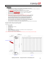
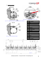
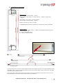
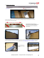
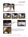
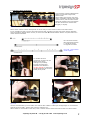
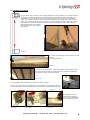
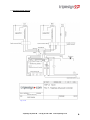
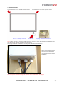
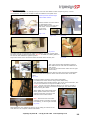
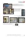
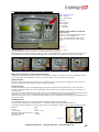
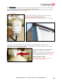
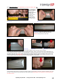
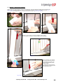
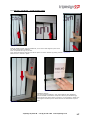
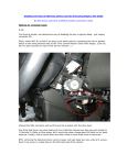
Users Manual
&
technical information
Rev. Date 2007-09-03
Contents:
1.
Preparations (1,2)
2.
Technical Drawings (3)
3.
How beams are put together (4)
4.
Mounting – Drive beam (5,6)
5.
Mounting – Drive mechanism (7)
6.
Mounting – Lower beam (8)
7.
Electrical wirings (9,10,11)
8.
Mounting – Side beams (12)
9.
Adjustment TAC3 (13)
10. Wind-sensor (14)
11. Aluquick system (15)
12. Alusolid/Cardboard system (16)
13. Maintenance (18)
14. Troubleshooting (18)
15. Example installations (18)
Please read all instructions before attempting to install the sign!
Please visit www.triplesign.com for the latest manual revision.
Important notes in this manual are marked in red, so pay some extra attention to it!
1.1 Preparations
•
•
•
•
•
•
•
A poor mounting will always result in problems and premature wear of the
parts. We have seen really poor installations that caused the drive mechanism to brake, so please be
very accurate when installing your Triplesign XP.
It is extremely important that the beams are mounted completely
horizontal/vertical and parallel, and that they do not tip forward, backward
or twists. NOTE! This is important!
Sign must always be installed absolutely square. Measure the diagonals
to ensure the correct shape of sign.
Make sure that all screws are tightened properly.
Always mount a rigid back sheet panel (wind break) behind the sign, preventing
wind turbulences and light shining through the prisms. In snowy locations, cut
out an opening along the lower end of the sign preventing accumulation of
snow. This opening should be approx. 10 cm high and made throughout the
length of the sign. Furthermore, in the event that there is a space between
sign and wind break, we strongly recommend side enclosures as well.
In event of extreme weather climates, heating cable can be ordered separately.
After the assemble, ensure that there are no mounting bolts or nuts inside
the drive beam that could get in the way of the rotating parts.
Check that there is a sufficient and equal gap between all the prisms (check all three faces).
All units of measure used in this manual are metric.
Note that: 1 inch = 25.4 mm ,1 foot = 304.8 mm
Tools that are needed:
•
8mm wrench
•
10mm wrench
•
3mm Allen key (included)
•
4mm Allen key
•
Water level
•
Pozi screwdriver
•
Drilling machine (power screwdriver is preferable) for the corresponding work.
•
Drills for corresponding wall types.
•
String for measurement of straightness.
Check carefully what type of wall/construction material and buy the correct fixing screws and bolts.
Rigid back sheet panel
Fig 1.1.A
Triplesign System AB
Fig 1.1B
+46 (0) 8 626 7350
www.triplesign.com
1
1.2 Preparations
Side view
Top/bottom view
Example installation of
distances
Perfect installation
Mounting distances can be ordered separately.
It’s extremely important that all beams are mounted straight!
Check ALL beams to ensure everything is square and straight!
DO NOT IGNORE OUR GUIDANCE! YOU WILL SHORTEN THE LIFETIME OR EVEN DAMAGE YOUR TRIPLESIGN IF
OUR INSTRUCTIONS ARE NOT BEING CARRIED OUT!
Triplesign System AB
+46 (0) 8 626 7350
www.triplesign.com
2
2.1 Technical drawings
Fig 2.1.B - Drive section axle connection points
Fig 2.1.A - Upper beam with drive sections and prism substainer.
Fig 2.1.C - Lower beam with retainer.
A
B
C
D
E
F
G
H
I
J
K
1
2
3
4
5
6
7
8
9
10
11
12
13
14
15
Drive beam mounting bracket
Screw (M6x16)
Nut & washer
Beam
Prism substainer
Prism retainer
Beam joiners
Joiner stop screw
Shaft connector screw (M6x25)
Vibration absorber
Locking nut
Drive shaft console
Drive shaft console
Slide bearing
Drive shaft
Ball bearing
Drive beam plate
Drive beam plate screw (M5x10)
Washer
Flexible pin
Claw
Triangle
Triangle bearing
Nut
Prism substainer
Screw (3,9x11)
Fig 2.1.D
Triplesign System AB
+46 (0) 8 626 7350
www.triplesign.com
3
3.1 How beams are put together
Measurements:
External height = Picture height + 245mm.
External width = No. prisms x CC (86 or 84mm) – (CC86=6, CC84=4mm)
+ 262mm
Picture width = No. prisms x CC (86 or 84mm).
Picture height = External height – 245mm.
CC86 is most common used in our signs.
For REPRO/original dimensions, please visit our website for further information.
Weight of signs:
20kg x WIDTH_OF_SIGN (metres) + WEIGHT_OF_PRISMS (Numbers of prisms x
prisms length (m) x E)
E = 1kg for aluminium prisms
E= 0,5kg for cardboard prisms
Fig 3.1.A
Fig 3.1.B
If your Triplesign XP is more than 4metres wide the beams are divided into two or more parts depending on the
total width of sign. If more than 8metres wide the sign has two “service beams” which makes service of motor
and switch easier if problem occurs.
Lower beams has draining holes drilled in the bottom to prevent accumulation of water/snow, this is the only
thing that differ from the drive beams (without the drive mechanism).
Triplesign System AB
+46 (0) 8 626 7350
www.triplesign.com
4
4.1 Mounting drive beam(s).
Fig 4.1.A
Fig 4.1.B
Tense a string (guidance) to ensure that beams are straight and place mounting distances between
wall/construction material and beams.
Use appropriate bolts depending on
wall/construction material. Preferable bolts
in M10 size. Place mounting brackets
every 600mm and ensure straightness
with distances.
Fig 4.1.C
Fig 4.1.D - Our 12m wide example installation.
When all mounting brackets are mounted we will prepare the beams. Depending on how wide the sign is, there
are some differences in mounting procedure (please check 3.1 - How beams are put together on page4).
Place 2pcs M6x16mm
(included) screw every
600mm.
Fig 4.1.E
Fig 4.1.F
Triplesign System AB
+46 (0) 8 626 7350
www.triplesign.com
5
4.2 Mounting drive beam(s).
Place a washer above mounting bracket (and
between nut), and secure the drive section by tighten
the M6 nut.
Ensure that beam is straight against the guidance
string!
Fig 4.2.A
The rest of this page is only applicable if your Triplesign XP is more than 4 meters wide or equipped
with more than 2 beams, see 3.1 - How beams are put together on page4
Fig 4.2.B
Fig 4.2.C
Fig 4.2.D
Slide the four joiners into the slot. Half of the joiners should be visible outside the beam.
Tighten with Allen key.
Merge beams (fit joiners in
correct beam slot).
Make sure the beams are
correctly merged and no chink
(gap) exists.
Tighten all joiners.
Fig 4.2.E
Fig 4.2.F
Do not forget to tighten stop screws inside the beam!
NOTE:
When dealing with a larger sign (8-14m wide) the very right and
very left section is around 400mm wide. This section is pre-mounted
from factory and should NOT have joiners inside the beam. This is
because it must be possible to remove this section from outside in
case of a service/maintenance task.
Fig 4.2.G
Triplesign System AB
+46 (0) 8 626 7350
www.triplesign.com
6
5.1 Mounting drive mechanism
Drive sections could be installed from
factory to minimize freight costs,
please check!
When sliding drive section into drive
beam, remember to always start with
motor section, and the motor should
always be closest to the end of beam.
All drive sections are marked with
R (right) or L (left).
Fig 5.1.A
Which motor section to start with depends on which side you have chosen to slide in all section from?
In our example we slide in all our drive sections from right, therefore we start with motor section marked L,
when all sections marked with L are out, we move over with R marked sections and the very last section is a
motor section marked R.
LM: Left motor section
RM: Right motor section
L: Left drive section
R: Right drive section
Fig 5.1.B - How sections
are fit together.
To combine all drive
mechanism we take use of a
M6x25 screw and a
looking nut (included).
In order to avoid noise
problems and vibrations
DO NOT FORGET to mount the
vibration absorber at the drive
shafts joiner points.
Fig 5.1.C
Fig 5.1.D
Fig 5.1.E
Fig 5.1.F
Use the included locking nut and make sure that the blue rubber is visible (the straight edge on nut should be
against the drive shaft). Tighten with a wrench and Allen key.
When shafts are connected to each other, slide it further into the beam and continue with next drive section.
Triplesign System AB
+46 (0) 8 626 7350
www.triplesign.com
7
6.1 Mounting lower beam
In most cases lower retainer sections (steel plates with prisms retainer) are already installed
from factory (slided into beams) to minimize freight, please remove them to facilitate the
installation. We must measure where to put lower beam and this can be done in different
ways. It is recommended to mount the complete side beams and mark the position of lower
beam. The mathematical way of doing this is to measure the side beams length and subtract
with 233mm. If your side beams is 3000mm long, the calculation is: 3000-233=2767mm.
Measurements are done between
the points that the arrow to the
left explains.
Fig 6.1.B - Typical view when measuring.
Fig 6.1.A
Drill holes every 600mm on lower beam. Use this
holes for
your mounting bolts…
Fig 6.1.C
Tense a string (guidance) to ensure that beams are straight and place
mounting distances between wall/construction material and beams if
necessary to make everything straight.
Fig 6.1.D
Use appropriate bolts depending on wall/construction material.
IMPORTANT! The head of the screw may not exceed 6mm, otherwise the prisms
could be damaged or even damage the drive mechanism if hitting the screw head.
Fig 6.1.E
See page6 for further
instructions regarding
how to merge the beams,
it’s the same procedure.
Fig 6.1.F
Fig 6.1.G
Triplesign System AB
Fig 6.1.H
+46 (0) 8 626 7350
www.triplesign.com
8
7.1 Electrical wiring diagram
Fig 7.1.A
Triplesign System AB
+46 (0) 8 626 7350
www.triplesign.com
9
7.2 Electrical wirings
Connect the three-wire on the left hand side motor
Fig 7.2.A - Example overview
Connect the five-wire on the right side motor
Terminal box
Triplesign Advanced Controller box
Note: Before 2007-04-01 customers needed to ground (connect to earth) the sign frame at installation spot,
now days the sign frame is grounded via left side motor.
The wiring needs to be routed before mounting side beams and lower retainers!
When you understand how the
electronics are connected we
move on to the next section and
route the wires needed for this
installation!
Fig 7.2.B - Wind-sensor, motor/switch, and power cable in TAC3 installation box
This box requires a ventilation plug to be installed due to condensation, see page13
Triplesign System AB
+46 (0) 8 626 7350
www.triplesign.com
10
7.3 Electrical wirings
Note: the following is just an example how you can route the cables to make everything work, in some
circumstances you might not be able to route the cables as we explain here.
Those pictures describe right
hand motor section.
Mount bracket on motor section
in appropriate holes.
Do the same for both right and
left motor. Use the included
3,9x11mm
black screw.
Fig 7.3.A
Fig 7.3.B
Fig 7.3.C
Fig 7.3.D
The cable entries are mounted on cables from factory, you only need to place
the entry correctly as pictures describes. Be sure to install the rubber gasket on
the correct side of bracket. Tighten by hand.
Right hand motor has 2 connections while left hand motor has only one.
Fig 7.3.E
This is the terminal box described in page10.
One cable from the TAC and two cables out to
each motor
(3 wires to left hand motor and 5 wires to right
hand motor).
Inside this box, connect all wires with the same colours to an appropriate
connection point as the picture shows. Mount terminal box cover when
done.
Fig 7.3.F
Route the cables inside the lower beam (preferable).
Let cables from motor section hang into the cable entry.
You could place them outside of beam, but we do not recommend it, but
in some circumstances it might be suitable to do so.
Advice : Do not mix up the different cables so you have to reroute it
again, therefore, be sure to connect everything on the motor section
before routing the cables.
When cables are routed inside lower
beam, please install lower retainer
sections and locate cut-outs at the
ends and secure cable entries.
Fig 7.3.G
Note : Pictures do not show lower
retainers which is normally mounted
from factory, so do not get confused.
Fig 7.3.H
Parts marked A (only marked in picture, not in reality) should be on the
ends with the cut-out parts nearest side beams.
Triplesign System AB
+46 (0) 8 626 7350
Fig 7.3.I
www.triplesign.com
11
8.1 Mount side beams
Start with removing plastic protection on the edges.
It’s preferable to let as much of the protection to be left on
beams to prevent damages on it.
Mostly side beams are being put together by customers, but in
some cases side beams are put together from factory.
Fig 8.1.A
If the beams are not connected to each other from
factory, attach the corresponding
beam to each other, suit (check all
edges) and tighten it together with
included M6x16 screw, washer and
nut.
Place a washer on each side of the
beam.
Fig 8.1.B
Fig 8.1.C
Fig 8.1.D
Attach wire to the wire clips which is fastened on side
beams (pre mounted from factory).
Fig 8.1.E
Fig 8.1.F
Fig 8.1.G
Mount side beams onto drive beam and then lower beam,
secure by using the included 4,8x16mm screw.
Fig 8.1.H
Triplesign System AB
+46 (0) 8 626 7350
www.triplesign.com
12
9.1 TAC3 (Triplesign Advanced Controller) adjustments
Main power switches
ON : upwards
OFF : Downwards
Buttons :
ESC: Go back
OK: Confirm
+: Increase
-: Decrease
Change display time for each side
(face 1,2,3) :
Press +/- to increase/decrease display
time on current visible side.
Note : Selected display times is now
saved into memory even after power
loss
Fig 9.1.A
Service mode (only enter this mode if you intend to perform some service tasks) :
To perform a service task you need to manually stop the sign, press OK.
Rotate the sign manually by pressing button A. There is also a SWITCH= indicator on LCD so that status of the
micro switch can be viewed without disassemble drive mechanism. When done, start sign by pressing OK.
Fig 9.1.B – Button OK
Fig 9.1.C – Increase (+)
Fig 9.1.D - Decrease (-)
Fig 9.1.E – Button A
Wind-sensor function (in extreme wind locations)
Support for wind-sensor (places the prisms on next side and stops the rotation until wind has reached a safety
point). Set points can be adjusted directly on the wind-sensor, see next page for instructions.
Safety function
Build-in functions for safety (if sign cannot turn side within 5sec it will stop and try again every 20 minutes in
48 hours). After 48hours the sign has to be manually restarted.
Warranty Notes
In order to avoid the risk of re-programming do not push two buttons at the same time or make any other
strange combinations which are not in accordance with the manual. The product guarantee is not covering reprogramming.
The TAC3 can not be exposed to any water. If there is condensation in the electric box please contact your local
distributor for a delivery of a ventilation plug to the box. The ventilation plug is standard for all
deliveries since 2007-04-01. For deliveries after 2007-04-01 the guarantee is not covering any damages due to
exposure to water.
Ventilation plug
The ventilation plug gives you a strong protection against damp and condensation.
The plug works with pressure compensation – ventilation through a damp protected membrane.
The plug should be installed on the side of the box in a low position in order to secure the function of the plug.
Material
Color
Temperature
Diameter of the hole in the box
Maximum diameter
IP 66 and 67
PA 6
Grey
-40 C +105 C
12mm
12,2mm
Fig 9.1.F
Triplesign System AB
+46 (0) 8 626 7350
www.triplesign.com
13
10.1 Wind-sensor
If the sign is going to be installed in a windy location, it’s preferable to mount a wind-sensor which stops the
sign from rotation when wind is above limits (adjustable at sensor position).
This sensor does not rotate more than 180degrees, which means it’s really important that the “wind wheels”
are in the wind directions. DO NOT TRY TO SPIN!
“wind wheel”
It’s very important that this wind-sensor is correctly mounted.
The sensor must be mounted just above the sign.
DO NOT MOUNT BELOW/UNDER THE SIGN!
Sensor must be mounted in the same wind directions as the sign.
Fig 10.1.A
Fig 10.1.B
Wind-sensor is pre wired from factory and includes a cable (total cable length: sign height + 5m).
Install wind sensor (pre mounted from factory on an aluminium angle bracket) and route the cables down to
TAC3 (see electrical wiring diagram on page9).
When sensor is mounted you have to make sure
that the rotating blades (“wind wheels”) are
correct.
At least one “wind wheel” must be directly affected
by the wind direction since this sensor does not
turn continuously. Again DO NOT TRY TO SPIN!
Default reset speed : 38km/h
Default switch speed : 50km/h
DO NOT CHANGE THIS UNLESS YOU HAVE A
REALLY GOOD REASON FOR IT!
Fig 10.1.C
Triplesign System AB
+46 (0) 8 626 7350
www.triplesign.com
14
11.1 Aluquick prisms (only applicable if you have an aluquick sign…)
You need 3pcs of
this duoblesided
adhesive tape on
each prisms.
Please cut them to
3-5cm long.
If plastic corner
profiles are
mounted from
factory you can
skip this section.
Fig 11.1.A
Fig 11.1.B
Fig 11.1.D - Apply the adhesive tape you
previously cutted to smaller pieces in the
MIDDLE of the prism on each side.
Fig 11.1.C
Fig 11.1.E
Fig 11.1.F
Fig 11.1.G
When tape is applied, please fit plastic corner profiles.
Start with the side which is going to be the highest part of sign. Leave ~1mm as picture to the left shows. Fit
corner profile and press it down to it’s correct position on aluminium prism tracks. You need to work downwards
the prism and press every 10cm. When arriving to the middle (where the tape is mounted) please remove the
adhesive protection and MAKE SURE you press down the plastic corner profile at this position, because it’s the
only thing that keeps this plastic profile from moving upwards or downwards.
Fig 11.1.H
Fig 11.1.I
At the bottom of the prism you will notice that the plastic corner profile is to short, and this is because we must
be able to insert/remove new printings. Be really careful that whole plastic corner profile is correct mounted in
the prism tracks.
Triplesign System AB
+46 (0) 8 626 7350
www.triplesign.com
15
11.2 Aluqick – Add/change printings
Stop the sign by switch power switches (see page13). Remove tape which holds the roll of printings.
First number is SIDE number (1, 2 or 3), next number is prism number. Preferable start with 1-1,
1-2, 1-3, 1-4 etc. When one side is done, move over to side 2 (2-1, 2-2, 2-3, 2-4).
Fig 11.2.A
Fig 11.2.B
Fig 11.2.C
Slide the new printing in from the bottom of the prism.
Push it gently up into the tracks of plastic corner profiles.
Fig 11.2.E
When printings has reached
the top you have to pull it a
little bit back and place the
printings behind the prism
retainer edge.
If replacing an old printings,
just push it up a little bit and
the slide/drag it out.
Fig 11.2.D
Fig 11.2.F
Triplesign System AB
+46 (0) 8 626 7350
www.triplesign.com
16
12.1 Alusolid / Cardboard – Install/change prisms
Fig 12.1.B
Fig 12.1.A
Start by pushing prism into the substainer, let it slant a few degrees (let it touch
the lower beam when installing).
Puch it upwards as long as you can.
Puch the prism against the sign and fit the prism on lower retainer by pulling it down. Fig 12.1.C
Make sure it is correct in place.
Fig 12.1.D
Cardboard prisms :
The only thing that differs in sign when dealing with cardboard
prisms instead of Alusolid is the prism retainer (no ball bearings).
When pulling the prism down to secure it on the retainer, please use
two fingers as above picture shows and fit the “backside” of prism
first.
Fig 12.1.E
Triplesign System AB
+46 (0) 8 626 7350
www.triplesign.com
17
13.1 Maintenance
Every year the sign needs to be disassembled to lubricate every rotational part.
It’s recommended to change the complete drive sections by new ones in 3-5 years.
Plastic parts needs a special grease for lubrication, please contact triplesign for prices.
14.1 Troubleshooting
Contact us for a complete service manual.
15.1 Example installations
Triplesign System AB
+46 (0) 8 626 7350
www.triplesign.com
18