1
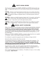
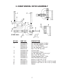
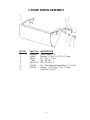
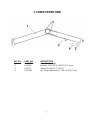
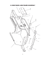
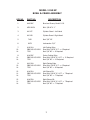
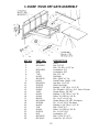
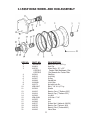
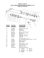
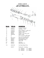
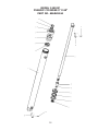
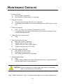
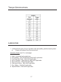
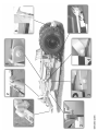
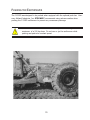
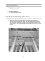
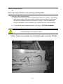
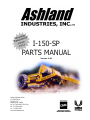
I-150-SP
PARTS MANUAL
Version 4-04
Ashland Industries Inc.
1115 Rail Drive
P.O. Box 717
Ashland, WI. 54806
Ph: 877-634-4622 Toll Free
Ph: 715-682-4622
Fx: 715-682-9717
www.ashlandind.com
HOW TO ORDER PARTS:
IMPORTANT
Parts must be ordered through your local authorized ASHLAND dealer.
Be sure to state MODEL and SERIAL NUMBER of your machine, PART NUMBER, DESCRIPTION
and QUANTITY needed.
Unless this is done, we cannot provide prompt service or assure shipment of the correct parts.
Ashland Industries weldable replacement parts are availabe to rebuild, modify or
update your scraper to current factory specifications.
INDEX
Page
Page
Page
Page
Page
Page
Page
Page
Page
Page
Page
Page
Page
Page
3.
Operators and Maintenance Instructions
4.
Safety Guidelines
5.
Illustration and Parts List- Swivel Hitch Assembly
6.
Illustration and Parts List - Apron Assembly
7.
Illustration and Parts List - Front End
8-9. Illustration and Parts List - Bowl and Frame Assembly
10.
Illustration and Parts List - Push Off Gate Assembly
11.
Illustration and Parts List - Rear Wheel and Hub Assembly
12.
Illustration and Parts List - Apron Cylinder, 4” x 13”
13.
Illustration and Parts List - Hydraulic Lift Cylinder, 5” x 20”
14-15. Illustration and Parts List - Pushoff Cylinder, 5” x 60”
16-20. Service Manual Appendix
21-23. Troubleshooting
24.
Warranty Statement
2
OPERATORS AND MAINTENANCE INSTRUCTIONS
This scraper is a durable piece of equipment and with proper care will yield many years
of trouble free operation. The scraper requires a power source with TWO 4 way (double
acting) hydraulic control valves.
The scraper should be greased at all points where grease fittings are provided. Connect
hydraulic hoses to the tractor and retract lift cylinders to REMOVE TRANSPORT LOCK
PINS (point A), then extend and retract all cylinders several times to force out any air from
the hydraulic cylinders and lines. Check the oil levels in the tractor hydraulic system and
add to maintain the proper level. Care should be used when adding oil or when disconnecting any oil line to keep all dirt out of the oil as dirt is a major factor in the failure of
hydraulic components.
When the scraper is placed into operation, the operator will have to “feel out” the
amount of depth of cut to obtain maximum loading efficiency. This is usually accomplished
by taking a lesser and more uniform cut; however, some soil conditions such as loose sand
may require a “pumping action” obtained by taking successive deep cuts and lifting out of
cut as the tractor begins to lose power or traction.
1.
After 10 hours work, all bolts should be checked and tightened if necessary.
2.
Every 10 hours all grease fittings should be lubricated.
3.
After 50 hours work, all bolts should be rechecked and tightened if necessary.
Check wheel bearings and adjust if necessary.
4.
After 300 hours work, clean and repack wheel bearings and replace, if necessary,
cutting edges, worn pins, etc.
5.
Tighten all wheel bolts after first two hours use. Check daily for two weeks. Keep
torqued to 750 ft. lbs.
6.
Maintain tire pressure at 45 to 50 psi.
3
SAFETY SIGNAL WORDS
Note the use of the signal words DANGER, WARNING and CAUTION with the safety messages. The appropriate signal word for each has been selected using the following guidelines:
DANGER: Indicates an imminently hazardous situation that, if not avoided, will result in
death or serious injury. This signal word is to be limited to the most extreme situations typically for machine components which, for functional purposes, cannot be
guarded.
WARNING: Indicates a potentially hazardous situation that, if not avoided, could result in
death or serious injury, and includes hazards that are exposed when guards are
removed. It may also be used to alert against unsafe practices.
CAUTION: Indicates a potentially hazardous situation that, if not avoided, may result in
minor or moderate injury. It may also be used to alert against unsafe practices.
GENERAL SAFETY GUIDELINES
Safety of the operator is one of the main concerns in designing and developing a new piece
of equipment. Designers and manufacturers build in as many safety features as possible.
However, every year many accidents occur which could have been avoided by a few seconds of thought and a more careful approach to handling equipment. You, the operator,
can avoid many accidents by observing the following precautions in this section. To avoid
personal injury, study the following precautions and insist those working with you, or for
you, follow them.
Replace any CAUTION, WARNING, DANGER or instruction safety decal that is not readable
or is missing. Location of such decals is indicated in this booklet.
Do not attempt to operate this equipment under the influence of drugs or alcohol.
Review the safety instructions with all users annually.
This equipment is dangerous to children and persons unfamiliar with its operation. The
operator should be a responsible adult familiar with farm machinery and trained in this
equipment’s operations. Do not allow persons to operate or assemble this unit
until they have read this manual and have developed a thorough understanding
of the safety precautions and of how it works.
To prevent injury or death, use a tractor equipped with a Roll Over Protective System
(ROPS). Do not paint over, remove or deface any safety signs or warning decals on your
equipment. Observe all safety signs and practice the instructions on them.
Never exceed the limits of a piece of machinery. If its ability to do a job, or to do so safely,
is in question - DON’T TRY IT.
4
I-150SP SWIVEL HITCH ASSEMBLY
KEY NO.
1.
2.
3.
4.
5.
6.
7.
8.
9.
10.
11.
PART NO.
A123299-08
A123299-07
AFN-00014
A123299-06
AFN-00018
A123299-03R
A123299-02
A123299-05
AFN-00018
A123299-01
A123299-04
ABS-00001
A123299-09
A123299-10
A123299-11
DESCRIPTION
Pin: Four Ear Drawbar To Hitch
Pin: Two Ear Drawbar To Hitch
Nut: 1-1/2” NC Slotted
Pin: Sq. Tab Head 2 X 18-1/2”
Nut: 1-1/2” NF Top Lock
A-Frame Hitch
C-Frame Hitch: Offset
Pin: Sq. Tab Head 1-1/2 X 12-1/2”
Nut: 1-1/2” NF Top Lock
Vertical Mounting Tube: 7 Hole
Wear Pad With Locking Legs
Bushing: 2-3/8” OD x 2” ID
Bushing: 2” OD x 1-1/2” ID x 1-1/2” (2 req’d)
Bushing: 2-3/8” OD x 2” ID x 1-1/2” (2 req’d)
Washer
5
I-150SP APRON ASSEMBLY
KEY NO.
1.
2.
3.
4.
5.
6.
7.
8.
PART NO.
A16025A
A16027
A6010
7450
AFB-00049
A10167
A10155
DESCRIPTION
Apron Model I-150
Bushing: 2” OD x 1-1/2” ID x 2” Long
Pin: 1-1/2” x 5-1/4”
Nut: 3/8” NC
Bolt: 3/8” NC x 3”
Pin: Claw Head w/Grease Fitting 1” x 3-1/16”
Bushing: 1-1/2” OD x 1” ID x 1” Long
Cotter Pin: 3/16 X 3”
6
I-150SP FRONT END
KEY NO.
1.
2.
3.
4.
PART NO.
A123297
A14039
A17513
A10152A
DESCRIPTION
Front End Assembly
Bushing: 2.375 OD X 2.000 ID X 2” Long
Transport Lock Pin: 1-1/8 X 5”
Pin, Frame Attachment, 2” OD x 8-1/16” Long
7
I-150SP BOWL AND FRAME ASSEMBLY
8
MODEL I-150 SP
BOWL & FRAME ASSEMBLY
KEY NO.
PART NO.
DESCRIPTION
1.
A16026C
Bowl and Frame, Model I-150
2.
AFB-00034
Bolt: 3/8 NC X 1”
3.
A10157
Cylinder Guard - Left Hand
4.
A10158
Cylinder Guard - Right Hand
5.
7450
Nut: 3/8” NC
6.
8078
Lockwasher: 3/8”
7.
10.
14.
A10011A
PB8P-NC-063-0200
7530
Left Cutting Edge
Plow Bolt: 5/8 NC X 2” -> 6 Required
Nut: 5/8” NC -> 6 Required
8.
11.
14.
A14029C
PB8P-NC-063-0250
7530
Center Cutting Edge
Plow Bolt: 5/8 NC X 2-1/2” -> 12 Required
Nut: 5/8” NC -> 12 Required
9.
10.
14.
A10010A
PB8P-NC-063-0200
7530
Right Cutting Edge
Plow Bolt: 5/8 NC X 2” -> 6 Required
Nut: 5/8” NC -> 6 Required
12.
11.
14.
A14031A
PB8P-NC-063-0250
7530
Left Shaver Bit
Plow Bolt: 5/8 NC X 2-1/2” -> 7 Required
Nut: 5/8” NC -> 7 Required
15.
11.
14.
A14032A
PB8P-NC-063-0250
7530
Right Shaver Bit
Plow Bolt: 5/8 NC X 2-1/2” -> 7 Required
Nut: 5/8” NC -> 7 Required
9
I-150SP PUSH OFF GATE ASSEMBLY
KEY NO.
PART NO.
DESCRIPTION
1.
2.
3.
4.
5.
6.
7.
8.
9.
10.
11.
12.
13.
14.
15.
16.
17.
18.
19.
20.
21.
22.
23.
24.
25.
26.
A14022
AFN-00006
----AFW-00002
8078
7450
A14023
AFB-00034
A16024
AFN-00024
A123306
A123307
A10008
14505
A10163
A10164
A6007A
AHF-00028
A123288
A10163
7036
A10164
A123305
8100
AFB-00033
AFP-00001
Brace
Nut: 3/4” NC
Bolt: 3/4” NC x 1-1/2” Lg.
Lockwasher: 3/4”
Lockwasher: 3/8”
Nut: 3/8” NC
Dirt Shield
Bolt: 3/8 NC x 1” Lg.
Pushoff Gate: Model I-150
Jam Nut: 1-1/4” NF
Roller: Rear Gate
Bushing” 1-5/8” OD x 1-1/4” ID
Pin: Shoulder 1-5/8” to 1-1/4” Zerk in Thread
Grease Fitting: 1/8” NPT
Bushing: 1-3/4” OD x 1-1/4” ID
Roller: 4-1/4 OD X 1-3/4 ID
Pin: 1-1/4” x 4-1/8” Lg.
Grease Fitting: 1/8” NPT -90 degree
Pin: 1-1/4 X 3-1/4” Tab Head
Bushing: 1-3/4” OD x 1-1/4” ID
Bolt: 1/2 NC X 2”
Roller: 4-1/4 OD X 1-3/4 ID
Pin: 1-1/4 X 2-3/4”
Lockwasher: 1/2”
Bolt: 1/2 NC X 2-1/2”
Cotter Pin: 1/4 X 3-1/2”
10
I-150SP REAR WHEEL AND HUB ASSEMBLY
KEY NO.
PART NO.
DESCRIPTION
1.
2.
3.
AFB-00026
A14004
A12036
Bolt 5/16” NC X 5/8” Lg.
Hub Cap
Wheel Ass’y. 25” x 25”
4.
5.
6.
7.
8.
9.
10.
11.
12.
13.
14.
15.
16.
17.
18.
19.
20.
21.
A12041
A12042
A12047
A10048
A10049A
A10172
AFB-00017
A12044
A14015
A14014
A12049
AFN-00001
A12035
A12048
A12037
A12038
A12039
A14016
Side Ring
Lock Ring
O-Ring
Spindle Nut
Lock Collar
Nut with Lock Pin
Bolt 1” NF X 6-1/2” Lg.
Spindle
Bearing Cone ( Timken 644 )
Bearing Cup ( Timken 632 )
Lug Nut
Lock Nut: 1” NF
Hub
Lug
Grease Seal ( National 416039 )
Bearing Cup (Timken# 854)
Bearing Cone (Timken#861)
Valve Stem
A12036-1
A12036-2
Center Dish Weldment, Flat
Six Gussets for Center Dish
11
MODEL I-150 SP
LEFT & RIGHT SIDE APRON CYLINDER 4 X 13
PART NO. A413H1
KEY NO.
PART NO.
DESCRIPTION
1.
2.
3.
4.
5.
6.
7.
8.
9.
10.
11.
12.
13.
14.
15.
16.
17.
18.
19.
A175H013
A300H06
A300H11
A300H12
A22H15
A22H15A
A300H13
A22H18
A22H17
A12H03
----A10167
A175H02
A45H05
A300H07
A300H05
A300H04
A300H03
A1217
A300H14B
Cylinder Barrel
O-Ring: 4” OD x 3/16”
Head Gland
Retainer Ring
O-Ring: 1-1/2” ID x 1/8”
Backup Washer: 1-1/2”
Gland Cap
Capscrew: 1/4” NC x 1”
Wiper Seal: 1-1/2” ID
Clevis End
Cotter Pin: 3/16” x 1-1/2”
Pin: Claw Head w/Grease Fitting 1” x 3-1/16”
Shaft: 1-1/2” Dia.
Piston Gasket: 1”
Piston: 4” Dia.
Backup Washer: 4” OD
Cast Iron Ring: 4” OD
Piston Nut, 1” NF
Pin: 1” x 3-1/2”
Packing Kit, Containing:
(1) A300H04
(2) A22H15
(2) A300H05
(1) A22H15A
(2) A300H06
(1) A22H17
(1) A45H05
12
MODEL I-150 SP
LIFT CYLINDER 5 X 20”
PART NO. A520H118-114
KEY NO.
PART NO.
DESCRIPTION
1.
2.
3.
4.
5.
6.
7.
8.
9.
10.
11.
12.*
13.
14.*
15.
A400H17
A400H04
A400H05
A400H06
A80H01
A60H52
A80H08A
A
A
AFP-00001
A80H02
A80H03
A80H04
A80H05
A80H06
Lock Nut: 1-1/4” NF
Cast Ring: 5” OD
Back-up Washer: 5” OD x 1/4”
O-Ring: 5” OD x 1/4”
Piston: 5” O.D.
O-Ring: 1-1/4” OD x 1/16”
Shaft: 2” Dia.
Pin: 2 X 9-7/16” w/Tab Head
Pin: 2 X 5-1/4 w/Tab Head”
Cotter Pin: 1/4 X 3-1/2”
Barrel Assembly: 5” ID
Head Gland: 5” OD
Seal: 2” ID
Head Cap
Wiper Seal 2” ID
*16.
A80H05A
One Piece Gland & Cap
A80H07
Packing Kit, Containing:
(1) A400H04
(1) A60H52
(3) A400H05
(1) A80H04
(2) A400H06
(1) A80H06
13
MODEL I-150 SP
PUSHOFF CYLINDER 5” X 60”
PART NO. A560H114A
14
MODEL I-150 SP
PUSHOFF CYLINDER 5 X 60”
PART NO. A560H114A
KEY NO.
1.
2.
3.
4.
5.
6.
7.
8.
9.
10.
11.
12.
13.
14.
15.
16.
17.
PART NO.
A140H20
A400H06
A400H05
A140H21
----A140H19
A140H07
A140H08
8602
A14033
A140H27
A175H06
A22H15
A140H22
A140H24
A140H25
AFN-00018
A140H28
18.
A9024
DESCRIPTION
Barrel Assembly: 5” Bore
O-Ring: 5” OD X 4-1/2” ID
Back Up Washer: 5” OD X 4-1/2” ID
Head Gland: 5”
Set Screw: 3/8” NC
Collar
Shaft Seal: 2-1/2” ID X 3” OD OU-Cup
Wiper Seal: 2-1/2” ID X 2-15/16” OD
Cotter Pin: 1/4” X 2”
Pin: 1-1/4” Dia. X 5” Lg.
Shaft: 2-1/2” Dia.
Spacer
O-Ring: 1-1/2” x 1-3/4” OD
Piston: 5”
Piston Seal: 5” OD X 4-1/4” ID
Wear Ring: 5” OD
Lock Nut: 1-1/2” NF
Packing Kit: Containing:
(1) A140H25
(1) A400H06
(1) A140H07
(1) A140H08
(1) A22H15
(1) A400H05
(1) A140H24
Pin: 1-1/4” x 4-3/4”
15
MAINTENANCE CHECKLIST
1. Grease all zerks.
a)
Every 8 hours of operation.
b)
See Lubrication Points section on next page.
2. Greasing the hubs.
a)
Re-pack wheel bearings after 600 hrs of operation.
b)
Completely clean grease out of hub and bearings every 1200 hours of operation.
3. Check tire pressure.
a)
29.5 - 25, 28-ply tire requires a tire pressure of 45-50.
If pressure drops, first secure valve stem, and if pressure continues to drop,
contact Ashland Industries.
4. Check all pins for signs of wear.
a)
Daily
5. Check wheel lug nut torque.
a)
After first 2 hours of operation.
b)
Recheck daily for next 2 weeks.
c)
Tighten wheel lug nuts in a star pattern.
d)
Torque wheel lug nuts to 750 ft-lbs.
6. Check and retighten all bolts.
a)
After initial 10 hours of use.
b)
Again after 50 hours of use.
c)
See Torque Specifications on next page.
7. Inspect cutting edges.
a)
Daily
b)
Replace cutting edges when center blade has been worn to approximately 6”
and side edges worn to approximately 4”.
CAUTION! Failure to replace worn cutting edges may result in unnecessary
wear to the earthmover sides and floor.
Note: Please specify left or right “L” shaped cutting edges when ordering replacements.
16
TORQUE SPECIFICATIONS
LUBRICATION
1. Grease all zerks every 8 hrs of operation with high quality, general-purpose grease.
a)
Grease until grease flows from around pin.
Lubrication Points (see Ill. on next page)
1.
2.
3.
4.
5.
6.
7.
8.
Hitch – Horizontal and vertical pins.
Lift Cylinders – Rod end &Trunion; Both left & right sides.
Front Arm Pivot Joint – Both left & right sides.
Apron Cylinders – Rod clevis pin; Both left & right sides.
Apron Pivot Pin – Both left & right sides.
Hold-down Rollers – Both left & right sides.
Floor Rollers – Both left & right sides.
Tapered Rollers – Both left & right sides.
17
18
HYDRAULIC SYSTEM
Standard Two-Circuit Hydraulic Plumbing
The apron cylinders and the push-off cylinder are controlled on the same circuit with
the sequence of the operation controlled by a sequence valve. The other hydraulic
circuit controls the lift cylinders on the earthmover.
*To adjust the sequence valve, see Troubleshooting section.
Optional Three-Circuit Hydraulic Plumbing
The apron cylinders, push-off cylinder, and lift cylinders are all on separate hydraulic
circuits.
Push-off Cylinder Hydraulic System
A pressure relief valve, in both two-circuit and three-circuit hydraulic plumbing, protects the pushoff cylinder hydraulic system. This pressure relief valve is designed to
limit the hydraulic oil pressure delivered to the push-off cylinder. This valve is preset
from the factory at 2000 psi.
*To adjust the pressure relief valve, see Troubleshooting section.
CAUTION! Relieve all hydraulic pressure before working on the hydraulic
system.
WARNING! High Pressure Fluid Hazard – To prevent serious injury or death
from high pressure fluid:
a) Relieve pressure on hydraulic system before repairing,
adjusting, or disconnecting.
b) Wear proper hand and eye protection when searching for
leaks.
c) Keep all components in good repair.
19
PUSHING THE EARTHMOVER
The I-150SP was designed to be pushed when equipped with the optional push-bar. However, Ashland Industries, Inc. STRONGLY recommends using extreme caution when
pushing the I-150SP earthmover to prevent any unnecessary damage.
CAUTION! The I-150SP earthmover must be pushed in a straight line with a
maximum of a 150 hp dozer. Do not ram or jar the earthmover while
pushing and push at a constant speed.
20
TROUBLESHOOTING
Introduction
With proper care and maintenance, the I-150SP will give many years of reliable service.
When a situation arises where the earthmover performance is not satisfactory, this section
will give some pointers on finding and correcting the problem.
Grease zerk will not take grease.
1. Grease zerk plugged.
a) Remove and replace grease zerk.
2. Pin is frozen.
a) Remove, clean, and inspect pin.
b) Replace pin if necessary.
3. Bushing grease passage is not aligned with grease zerk.
a) Remove, clean, inspect, and realign bushing.
b) Replace bushing if necessary and realign.
Push-off rollers do not roll.
1. The rollers need lubrication.
a) Check zerk hole and grease.
b) Remove pin, clean, inspect, and replace if necessary.
2. The roller bushing is worn out.
a) Remove roller assembly and replace bushing.
b) See parts manual.
Cylinders will not hold in preset position, i.e. the cylinder creeps.
1. Seals leaking internally.
a) Remove and replace seal kit.
21
Machine cuts unevenly.
1. Cutting edges worn unevenly.
a) Replace cutting edges.
2. Improperly inflated tires.
a) Check air pressure in tires.
Push-off cylinder stalls during ejection process.
1. Adjust pressure relief valve bypass pressure.
a) Remove the acorn nut from the end of the pressure relief valve with a ½”
wrench to expose the adjustment screw. Turn the adjustment screw, using a
4mm hex wrench, clockwise to increase pressure and counter-clockwise to decrease pressure. Use a pressure gauge in the hydraulic line as shown, to set the
pressure.
22
Apron closes slowly
or
Apron and push-off are not working well together.
1. Sequence valve needs adjusting.
a) Remove acorn nut from end of sequence valve with a ½” wrench. Turn adjustment screw, using a 4mm hex wrench, clockwise until front apron rises before
the push-off advances while the earthmover is empty. Turn the adjustment
screw an additional ¼ turn clockwise, then replace the acorn nut and tighten.
b) Torque check valve assembly and int. pilot plug to 25 ft-lbs maximum.
CAUTION! Overtightening check valve assembly and int. pilot plug will cause
internal damage to the sequence valve.
* Note: Check valve assembly may leak slightly when torqued to 25 ft-lbs.
23
Limited Warranty Statement
Ashland Industries Inc. warrants each new product to be free from defects in material and workmanship. This warranty is applicable only for the normal service life expectancy of the product or
components, not to exceed six consecutive months from the date of delivery of the new
Ashland Industries product to the original purchaser, or the date the product is first put into service
via a rental agreement or other means, whichever occurs first.
Genuine Ashland Industries Inc. replacement parts and components will be warranted for 30 days
from date of purchase, or the remainder of the original equipment warranty period, whichever is
longer.
Under no circumstances will it cover any merchandise or components thereof, which in the opinion
of the company, has been subjected to misuse, unauthorized modification, alterations, an accident
or if repairs have been made with parts other than those obtained through Ashland Industries Inc.
Ashland Industries Inc. in no way warrants Tires since these items are warranted separately by
their respective manufacturer. Please call Ashland Industries Inc. to receive phone numbers of tire
suppliers.
Ashland Industries Inc. in no way warrants wearable items such as cutting edges, front dolly wheel
balls, socket halves.
Our obligation under this warranty shall be limited to repairing or replacing, free of charge to the
original purchaser, any part that, in our judgement, shall show evidence of such defect, provided
further that such part shall be returned within 30 days from the date of failure to Ashland Industries Inc. routed through the dealer and distributor from whom the purchase was made, transportation charges prepaid. Upon warranty approval proper credits will be reimbursed for transportation.
This warranty shall not be interpreted to render Ashland Industries Inc. liable for injury or damages
of any kind or nature to person or property. This warranty does not extend to the loss revenue,
extra labor cost associated with downtime, substitute machinery, rental or for any other reason.
Except as set forth above, Ashland Industries Inc. shall have no obligation or liability of any kind
on account of any of its equipment and shall not be liable for special or consequential damages.
Ashland Industries Inc. make no other warranty, expressed or implied, and, specifically, Ashland
Industries Inc. disclaims any implied warrant or merchantability or fitness for a particular purpose.
Some states or provinces do not permit limitations or exclusions of implied warranties or incidental
or consequential damages, so the limitations or exclusion in this warranty may not apply.
This warranty is subject to any existing conditions of supply which may direct affect our ability to
obtain materials or manufacture replacement parts.
Ashland Industries Inc. reserves the right to make improvements in design or changes in specifications at any time, without incurring any obligation to owners of units previously sold
No one is authorized to alter, modify or enlarge this warranty nor the exclusion, limitations and
reservations.
Ashland Industries Inc.
Warranty Department
24