Download FSP 150SP-100 R6.1.1..

Transcript
FSP 150SP-100
Fiber Service Platform 150SP-100
Installation and Operations
User Manual
Product Release 6.1.1
Document Issue: A (February 2014)
Copyright © 2001-2014 ADVA Optical Networking SE
All rights reserved. Hardware and software mentioned in this document includes software developed
by ADVA Optical Networking SE (“ADVA Optical Networking“), the Apache Software Foundation
(http://www.apache.org), Teodor Danciu (http://jasperreports.sourceforge.net), and/or other open
source software. Some software was created using ORBacus for Java by Object-Oriented Concepts,
Inc.
Trademarks
The terms ADVATM, FSP 3000®, EtherjackTM and the EtherjackTM logo are trademarks or registered
trademarks of ADVA Optical Networking in the United States, Germany and/or other countries. All other
company products or services mentioned in this document may be trademarks or service marks of
ADVA Optical Networking or their respective owner.
Patents
The content described in this document may be covered by patents or pending patent applications of
ADVA Optical Networking. The furnishing of this document does not give you any license to these patents.
Disclaimers
Nothing in this document shall be construed as granting any license or rights with respect to its content
or the patents and trademarks mentioned above. The content of this document may include technical
inaccuracies or typographical errors, and is subject to change at any time without notice. Reliance on
this content is at the relying party's sole risk and will not create any liability or obligation for ADVA Optical Networking. Any references in this document to publications and/or Internet sites that are not from
ADVA Optical Networking are provided for convenience only and do not in any manner serve as an
endorsement of those publications and/or Internet sites. The materials within those publications and/or
Internet sites are not part of the materials for any ADVA Optical Networking information, product, or
service, and use of those publications and/or Internet sites is at your own risk.
THE CONTENT OF THIS DOCUMENT IS PROVIDED ''AS IS'' AND ANY EXPRESSED OR IMPLIED
WARRANTIES, INCLUDING, BUT NOT LIMITED TO, THE IMPLIED WARRANTIES OF MERCHANTABILITY AND FITNESS FOR A PARTICULAR PURPOSE ARE DISCLAIMED. IN NO EVENT SHALL
ADVA OPTICAL NETWORKING, ITS AFFILIATES, EMPLOYEES, OFFICERS OR ITS SUPPLIERS
BE LIABLE FOR ANY DIRECT, INDIRECT, INCIDENTAL, SPECIAL, EXEMPLARY, OR CONSEQUENTIAL DAMAGES (INCLUDING, BUT NOT LIMITED TO, PROCUREMENT OF SUBSTITUTE
GOODS OR SERVICES; LOSS OF USE, DATA, OR PROFITS; OR BUSINESS INTERRUPTION)
HOWEVER CAUSED AND BASED ON ANY THEORY OF LIABILITY, WHETHER IN CONTRACT,
STRICT LIABILITY, OR TORT (INCLUDING NEGLIGENCE OR OTHERWISE) ARISING IN ANY
WAY OUT OF THE USE OF THIS DOCUMENT, EVEN IF ADVISED OF THE POSSIBILITY OF SUCH
DAMAGE. THE SAME APPLIES FOR ANY HARDWARE OR SOFTWARE COVERED BY THIS DOCUMENT, UNLESS A SIGNED AGREEMENT WITH ADVA OPTICAL NETWORKING OR THE APPLICABLE PRODUCT LIABILITY LAW EXPRESSLY STATES OTHERWISE.
ADVA Optical Networking SE
5755 Peachtree Industrial Blvd
Norcross, Georgia 30092
USA
Phone +1 678 728 8600
Fax
+1 678 728 8788
http://www.advaoptical.com
Table of Contents
Table of Contents . . . . . . . . . . . . . . . . . . . . . . . . . . . . . . 3
List of Figures . . . . . . . . . . . . . . . . . . . . . . . . . . . . . . . . 13
List of Tables. . . . . . . . . . . . . . . . . . . . . . . . . . . . . . . . . 21
FSP 150SP-100 R6.1.1 80000026364 Issue: A, © 2014 ADVA Optical Networking SE - Confidential
Chapter 1
SP-100 Overview . . . . . . . . . . . . . . . . . . 23
Document Overview . . . . . . . . . . . . . . . . . . . . . . .
Audience . . . . . . . . . . . . . . . . . . . . . . . . . . . . .
Related Documentation. . . . . . . . . . . . . . . . . . .
Documentation Feedback . . . . . . . . . . . . . . . . .
Obtaining Technical Assistance . . . . . . . . . . . . .
SP-100 Product Overview . . . . . . . . . . . . . . . . . . .
eVision Web Browser Management Tool . . . . .
Command Line Interface . . . . . . . . . . . . . . .
Simple Network Management Protocol (SNMP)
Syncjack™ Suite. . . . . . . . . . . . . . . . . . . . . . . . . .
Tapping Mode. . . . . . . . . . . . . . . . . . . . . . . . . . . .
Parallel Mode . . . . . . . . . . . . . . . . . . . . . . . . . . . .
Tester Mode . . . . . . . . . . . . . . . . . . . . . . . . . . . . .
Clock Accuracy . . . . . . . . . . . . . . . . . . . . . . . . . . .
Reference and Source Signal . . . . . . . . . . . . . . .
TIE Post Processing . . . . . . . . . . . . . . . . . . . . .
Clock Accuracy Status (GUI) . . . . . . . . . . . . . . .
Clock Analysis . . . . . . . . . . . . . . . . . . . . . . . . . . .
Frequency Performance Estimation. . . . . . . . . . .
Phase Performance Estimation . . . . . . . . . . . . . .
PTP Clock Probe . . . . . . . . . . . . . . . . . . . . . . . . . .
Clock Analysis Status (GUI). . . . . . . . . . . . . . . .
PTP Network Analysis . . . . . . . . . . . . . . . . . . . . . .
PTP Network Usability Score . . . . . . . . . . . . . . .
Installation and Operations Manual
.
.
.
.
.
.
.
.
.
.
.
.
.
.
.
.
.
.
.
.
.
.
.
.
.
.
.
.
.
.
.
.
.
.
.
.
.
.
.
.
.
.
.
.
.
.
.
.
.
.
.
.
.
.
.
.
.
.
.
.
.
.
.
.
.
.
.
.
.
.
.
.
.
.
.
.
.
.
.
.
.
.
.
.
.
.
.
.
.
.
.
.
.
.
.
.
.
.
.
.
.
.
.
.
.
.
.
.
.
.
.
.
.
.
.
.
.
.
.
.
.
.
.
.
.
.
.
.
.
.
.
.
.
.
.
.
.
.
.
.
.
.
.
.
.
.
.
.
.
.
.
.
.
.
.
.
.
.
.
.
.
.
.
.
.
.
.
.
.
.
.
.
.
.
.
.
.
.
.
.
.
.
.
.
.
.
.
.
.
.
.
.
.
.
.
.
.
.
.
.
.
.
.
.
.
.
.
.
.
.
.
.
.
.
.
.
.
.
.
.
.
.
.
.
.
.
.
.
.
.
.
.
.
.
.
.
.
.
.
.
.
.
.
.
.
.
.
.
.
.
.
.
.
.
.
.
.
.
.
.
.
.
.
.
.
.
.
.
.
.
.
.
.
.
.
.
.
.
.
.
.
.
.
.
.
.
.
.
.
.
.
.
.
.
.
.
.
.
.
.
.
.
.
.
.
.
.
.
.
.
.
.
.
.
.
.
.
.
.
.
.
.
.
.
.
.
.
.
.
.
.
.
.
.
.
.
.
.
.
.
.
.
.
.
.
.
.
.
.
.
.
.
.
.
.
.
.
.
.
.
.
.
.
.
.
.
.
.
.
.
.
.
.
.
.
.
.
.
.
.
.
.
.
.
.
.
.
.
.
.
.
.
.
.
.
.
.
.
.
.
.
.
.
.
.
.
.
.
25
26
26
26
26
28
29
30
30
30
33
34
35
36
37
37
38
38
38
39
40
41
42
42
3
4
.
.
.
.
.
.
.
.
.
.
.
.
.
.
.
.
.
.
.
.
.
.
.
.
.
.
.
.
.
.
.
.
.
.
.
.
.
.
.
.
.
.
.
.
.
.
.
.
.
.
.
.
.
.
.
.
.
.
.
.
.
.
.
.
.
.
.
.
.
.
.
.
.
.
.
.
.
.
.
.
.
.
.
.
.
.
.
.
.
.
.
.
.
.
.
.
.
.
.
.
.
.
.
.
.
.
.
.
.
.
.
.
.
.
.
.
.
.
.
.
.
.
.
.
.
.
.
.
.
.
.
.
.
.
.
.
.
.
.
.
.
.
.
.
.
.
.
.
.
.
.
.
.
.
.
.
.
.
.
.
.
.
.
.
.
.
.
.
.
.
.
.
.
.
.
.
.
.
.
.
.
.
.
.
.
.
.
.
.
.
.
.
.
.
.
.
.
.
.
.
.
.
.
.
.
.
.
.
.
.
.
.
.
.
.
.
.
.
.
.
.
.
.
.
.
.
.
.
.
.
.
.
.
.
.
.
.
.
.
.
.
.
.
.
.
.
.
.
.
.
.
.
.
.
.
.
.
.
.
.
.
.
.
.
.
.
.
.
.
.
.
.
.
.
.
.
.
.
.
.
.
.
.
.
.
.
.
.
.
.
.
.
.
.
.
.
.
.
.
.
.
.
.
.
.
.
.
.
.
.
.
.
.
.
.
.
.
.
.
.
.
.
.
.
.
.
.
.
.
.
.
.
.
.
.
.
.
.
.
.
.
.
.
.
.
.
.
.
.
.
.
.
.
.
.
.
.
.
.
.
.
.
.
.
.
.
.
.
.
.
.
.
.
.
.
.
.
.
.
.
.
.
.
.
.
.
.
.
.
.
.
.
.
.
.
.
.
.
.
.
.
.
.
.
.
.
.
.
.
.
.
.
.
.
.
.
.
.
.
.
.
.
.
.
.
.
.
.
.
.
.
.
.
.
.
.
.
.
.
.
.
.
.
.
.
.
.
.
.
.
.
.
.
.
.
.
.
.
.
.
.
.
.
.
.
.
.
.
.
.
.
.
.
.
.
.
.
.
.
.
.
.
.
.
.
.
.
.
.
.
.
.
.
.
.
.
.
.
.
.
.
.
.
.
.
.
.
.
.
.
.
.
.
.
.
.
.
.
.
.
.
.
.
.
.
.
.
.
.
.
.
.
.
.
.
.
.
.
.
.
.
.
.
.
.
.
43
43
43
43
44
45
56
56
58
58
59
59
59
59
59
60
60
60
61
61
61
61
61
61
62
62
62
62
62
63
63
63
65
65
65
68
69
69
71
Installation and Operations Manual
FSP 150SP-100 R6.1.1 80000026364 Issue: A, © 2014 ADVA Optical Networking SE - Confidential
PTP Network Analysis Status (GUI). . . . . . . . . . . . . .
Product Applications . . . . . . . . . . . . . . . . . . . . . . . . . .
Timing and Synchronization. . . . . . . . . . . . . . . . . . .
Synchronous Ethernet . . . . . . . . . . . . . . . . . . . .
System Clock Reference . . . . . . . . . . . . . . . . . . .
Precision Time Protocol (PTP) . . . . . . . . . . . . . . .
Port Loopback . . . . . . . . . . . . . . . . . . . . . . . . . .
Port Facility Loopback . . . . . . . . . . . . . . . . . . . .
SNMP Dying Gasp . . . . . . . . . . . . . . . . . . . . . . .
Resolving Target Addresses . . . . . . . . . . . . . .
Management Overview . . . . . . . . . . . . . . . . . . . . . . . .
Management Interfaces . . . . . . . . . . . . . . . . . . . . .
Command Line Interface . . . . . . . . . . . . . . . . . .
Simple Network Management Protocol (SNMP) . . .
eVision Web Browser Management Tool . . . . . . . .
Management Features . . . . . . . . . . . . . . . . . . . . . .
User Management and Security . . . . . . . . . . . . . .
Local User Profile Management . . . . . . . . . . . .
SNMP User Management . . . . . . . . . . . . . . . .
ACL Management . . . . . . . . . . . . . . . . . . . . .
Security Banner . . . . . . . . . . . . . . . . . . . . . .
RADIUS or TACACS+ . . . . . . . . . . . . . . . . . . .
Provisioning . . . . . . . . . . . . . . . . . . . . . . . . . . .
Communications Provisioning . . . . . . . . . . . . .
Operations Provisioning . . . . . . . . . . . . . . . . . . .
Provisioning System Options . . . . . . . . . . . . .
Provisioning Network Elements . . . . . . . . . . . .
Provisioning Secure Access . . . . . . . . . . . . . .
Provisioning Alarms . . . . . . . . . . . . . . . . . . . .
Provisioning Performance Monitoring . . . . . . . .
Alarm Generation and Monitoring . . . . . . . . . . . .
SP-100 Hardware Description. . . . . . . . . . . . . . . . . . . .
Power Supply. . . . . . . . . . . . . . . . . . . . . . . . . . . . .
Connector and LED Descriptions. . . . . . . . . . . . . . . .
Front Panel Connector Descriptions . . . . . . . . . . .
System LEDs. . . . . . . . . . . . . . . . . . . . . . . . . . .
Local Management Port LEDs . . . . . . . . . . . . . . .
Ethernet Access Port Client Ethernet Facility LEDs .
Network Ethernet Port LEDs . . . . . . . . . . . . . . . .
Table of Contents
FSP 150SP-100 R6.1.1 80000026364 Issue: A, © 2014 ADVA Optical Networking SE - Confidential
Chapter 2
Physical Installation . . . . . . . . . . . . . . . . 73
Introduction . . . . . . . . . . . . . . . . . . . . . . . . . . . . . . . . . . . . . . . . . . . . .
Physical Installation . . . . . . . . . . . . . . . . . . . . . . . . . . . . . . . . . . . . . . .
Preparing for Installation. . . . . . . . . . . . . . . . . . . . . . . . . . . . . . . . . .
Verifying Site Readiness . . . . . . . . . . . . . . . . . . . . . . . . . . . . . . . . . .
Requirements . . . . . . . . . . . . . . . . . . . . . . . . . . . . . . . . . . . . . . . . .
Cables . . . . . . . . . . . . . . . . . . . . . . . . . . . . . . . . . . . . . . . . . . . .
Tools . . . . . . . . . . . . . . . . . . . . . . . . . . . . . . . . . . . . . . . . . . . . .
Unpack and Inspect the FSP 150SP Equipment . . . . . . . . . . . . . . . . . .
Returning Equipment . . . . . . . . . . . . . . . . . . . . . . . . . . . . . . . . . .
Install the FSP 150SP . . . . . . . . . . . . . . . . . . . . . . . . . . . . . . . . . . . .
Mounting Kits . . . . . . . . . . . . . . . . . . . . . . . . . . . . . . . . . . . . .
Mounting Options . . . . . . . . . . . . . . . . . . . . . . . . . . . . . . . . . .
Mounting a Single FSP SP-100 via a Standard or Extended 19”
Configuration . . . . . . . . . . . . . . . . . . . . . . . . . . . . . . . . . . .
Mounting a Single SP-100 via a 23” Standard or Extended / ETSI
Extended Configuration . . . . . . . . . . . . . . . . . . . . . . . . . . . .
Mounting Dual SP-100s via a 19” Standard or Extended
Configuration . . . . . . . . . . . . . . . . . . . . . . . . . . . . . . . . . . .
Mounting Dual SP-100 via a 23” Standard or Extended / ETSI
Extended Configuration . . . . . . . . . . . . . . . . . . . . . . . . . . . .
Mounting the SP-100 to a Wall . . . . . . . . . . . . . . . . . . . . . . . . .
Installing a Standalone Chassis. . . . . . . . . . . . . . . . . . . . . . . . .
Route and Connect Copper Cables . . . . . . . . . . . . . . . . . . . . . . . . . . . . .
Access / Network Interface Copper Cables . . . . . . . . . . . . . . . . . . . . .
Ethernet DCN Connections . . . . . . . . . . . . . . . . . . . . . . . . . . . . . . . .
Serial Console Port Connection . . . . . . . . . . . . . . . . . . . . . . . . . . . . .
USB Port Connections . . . . . . . . . . . . . . . . . . . . . . . . . . . . . . . . . . . .
GPS Port Connections . . . . . . . . . . . . . . . . . . . . . . . . . . . . . . . . . . . .
BITS IN and BITS OUT Cables . . . . . . . . . . . . . . . . . . . . . . . . . . . . . .
Time of Day Cable . . . . . . . . . . . . . . . . . . . . . . . . . . . . . . . . . . . . . .
Install SFPs and Route Optical Cables . . . . . . . . . . . . . . . . . . . . . . . . . . .
Install SFP Interfaces . . . . . . . . . . . . . . . . . . . . . . . . . . . . . . . . . . . .
Route Fiber Optic Cables . . . . . . . . . . . . . . . . . . . . . . . . . . . . . . . . . .
Connect Power Cables and Apply Power. . . . . . . . . . . . . . . . . . . . . . . . . .
Connect Optional Earth (Frame Ground) Cable. . . . . . . . . . . . . . . . . . .
Connect AC Power . . . . . . . . . . . . . . . . . . . . . . . . . . . . . . . . . . . . . .
Connect -48 VDC Power . . . . . . . . . . . . . . . . . . . . . . . . . . . . . . . . . .
Connect +24 VDC Power . . . . . . . . . . . . . . . . . . . . . . . . . . . . . . . . . .
Start-Up LED Sequence. . . . . . . . . . . . . . . . . . . . . . . . . . . . . . . . . . .
LED Start-Up. . . . . . . . . . . . . . . . . . . . . . . . . . . . . . . . . . . . . . . .
Installation and Operations Manual
.
.
.
.
.
.
.
.
.
.
.
.
73
73
74
74
76
76
79
80
81
81
82
82
. 84
. 85
. 88
.
.
.
.
.
.
.
.
.
.
.
90
92
94
95
96
97
97
98
98
99
99
100
100
103
104
105
107
108
110
112
114
5
Power On Lamp Test . . . . . . . . . . . . . . . . . . . . . . .
Measure Optical Power . . . . . . . . . . . . . . . . . . . . . . . . . .
Optical Attenuation . . . . . . . . . . . . . . . . . . . . . . . .
Clean Fiber Connections . . . . . . . . . . . . . . . . . . . . . . .
Precautions When Connecting Fiber Optic Cables . . . . . .
Connect Fiber Cables to Access Port or Network Port . . .
To Power Off . . . . . . . . . . . . . . . . . . . . . . . . . . . . . . . . .
Connector Pin Assignments . . . . . . . . . . . . . . . . . . . . . . .
Power Supply Unit Connector Pin Assignments. . . . . . . .
LAN Connector Pin Assignments . . . . . . . . . . . . . . . . . .
Serial Console Port Connector Pin Assignments . . . . . . .
RJ-48c BITS Connector Pin Description and Assignments
Time of Day (TOD) Connector Pin Assignments . . . . . . .
.
.
.
.
.
.
.
.
.
.
.
.
.
.
.
.
.
.
.
.
.
.
.
.
.
.
.
.
.
.
.
.
.
.
.
.
.
.
.
.
.
.
.
.
.
.
.
.
.
.
.
.
.
.
.
.
.
.
.
.
.
.
.
.
.
.
.
.
.
.
.
.
.
.
.
.
.
.
.
.
.
.
.
.
.
.
.
.
.
.
.
.
.
.
.
.
.
.
.
.
.
.
.
.
.
.
.
.
.
.
.
.
.
.
.
.
.
115
115
115
116
116
117
117
118
118
120
121
122
123
eVision Web Browser Management
Tool . . . . . . . . . . . . . . . . . . . . . . . . . . . . 125
Introduction . . . . . . . . . . . . . . . . . . . . . . . . . . .
Users and Security . . . . . . . . . . . . . . .
Software Upgrade . . . . . . . . . . . . . . . .
Database Configuration Management . .
Minimum System Requirements . . . . . . . . . . .
Logging On and Off . . . . . . . . . . . . . . . . . . . . . .
Logging On . . . . . . . . . . . . . . . . . . . . . . . . .
Logging Off . . . . . . . . . . . . . . . . . . . . . . . . .
User Session Timeout . . . . . . . . . . . . . . . . . .
Getting Familiar with eVision . . . . . . . . . . . . . . .
About the Workspace . . . . . . . . . . . . . . . . . .
Title Bar . . . . . . . . . . . . . . . . . . . . . . . . .
Menu Bar . . . . . . . . . . . . . . . . . . . . . . . .
Tool Bar . . . . . . . . . . . . . . . . . . . . . . . . .
Selection Tree . . . . . . . . . . . . . . . . . . . . .
Details Pane . . . . . . . . . . . . . . . . . . . . . .
Operations and Provisioning Field Types
Command Buttons . . . . . . . . . . . . . . .
Alarms Pane . . . . . . . . . . . . . . . . . . . . . .
Keyboard Navigation . . . . . . . . . . . . . . . .
eVision Applications . . . . . . . . . . . . . . . . . . . . .
Configuration View . . . . . . . . . . . . . . . . . . . . . .
Maintenance View . . . . . . . . . . . . . . . . . . . . . . .
Viewing Entities in Maintenance View . . . . . . .
6
.
.
.
.
.
.
.
.
.
.
.
.
.
.
.
.
.
.
.
.
.
.
.
.
.
.
.
.
.
.
.
.
.
.
.
.
.
.
.
.
.
.
.
.
.
.
.
.
.
.
.
.
.
.
.
.
.
.
.
.
.
.
.
.
.
.
.
.
.
.
.
.
.
.
.
.
.
.
.
.
.
.
.
.
.
.
.
.
.
.
.
.
.
.
.
.
.
.
.
.
.
.
.
.
.
.
.
.
.
.
.
.
.
.
.
.
.
.
.
.
.
.
.
.
.
.
.
.
.
.
.
.
.
.
.
.
.
.
.
.
.
.
.
.
.
.
.
.
.
.
.
.
.
.
.
.
.
.
.
.
.
.
.
.
.
.
.
.
.
.
.
.
.
.
.
.
.
.
.
.
.
.
.
.
.
.
.
.
.
.
.
.
.
.
.
.
.
.
.
.
.
.
.
.
.
.
.
.
.
.
.
.
.
.
.
.
.
.
.
.
.
.
.
.
.
.
.
.
.
.
.
.
.
.
.
.
.
.
.
.
.
.
.
.
.
.
.
.
.
.
.
.
.
.
.
.
.
.
.
.
.
.
.
.
.
.
.
.
.
.
.
.
.
.
.
.
.
.
.
.
.
.
.
.
.
.
.
.
.
.
.
.
.
.
.
.
.
.
.
.
.
.
.
.
.
.
.
.
.
.
.
.
.
.
.
.
.
.
.
.
.
.
.
.
.
.
.
.
.
.
.
.
.
.
.
.
.
.
.
.
.
.
.
.
.
.
.
.
.
.
.
.
.
.
.
.
.
.
.
.
.
.
.
.
.
.
.
.
.
.
.
.
.
.
.
.
.
.
.
.
.
.
.
.
.
.
.
.
.
.
.
.
.
.
.
.
.
.
.
.
.
.
.
.
.
.
.
.
.
.
.
.
.
.
.
.
.
.
.
.
.
.
.
.
.
.
.
.
.
.
.
.
.
.
.
.
.
.
.
.
.
.
.
.
.
125
128
128
128
129
130
130
132
133
133
134
135
135
136
137
138
140
141
141
141
142
143
145
148
Installation and Operations Manual
FSP 150SP-100 R6.1.1 80000026364 Issue: A, © 2014 ADVA Optical Networking SE - Confidential
Chapter 3
.
.
.
.
.
.
.
.
.
.
.
.
.
Table of Contents
Editing Alarm Attributes . .
Loopbacks . . . . . . . . . . . .
Performance Monitoring View .
Precision Time Protocol . . . . .
SyncJack . . . . . . . . . . . . . . .
FSP 150SP-100 R6.1.1 80000026364 Issue: A, © 2014 ADVA Optical Networking SE - Confidential
Chapter 4
.
.
.
.
.
.
.
.
.
.
.
.
.
.
.
.
.
.
.
.
.
.
.
.
.
.
.
.
.
.
.
.
.
.
.
.
.
.
.
.
.
.
.
.
.
.
.
.
.
.
.
.
.
.
.
.
.
.
.
.
.
.
.
.
.
.
.
.
.
.
.
.
.
.
.
.
.
.
.
.
.
.
.
.
.
.
.
.
.
.
.
.
.
.
.
.
.
.
.
.
.
.
.
.
.
.
.
.
.
.
.
.
.
.
.
.
.
.
.
.
.
.
.
.
.
.
.
.
.
.
.
.
.
.
.
.
.
.
.
.
.
.
.
.
.
.
.
.
.
.
.
.
.
.
.
.
.
.
.
.
149
151
151
151
151
Operations Provisioning . . . . . . . . . . . . 153
Introduction . . . . . . . . . . . . . . . . . . . . . . . . . . . . . . . . . . . . . . . . . . .
Provisioning the SP-100. . . . . . . . . . . . . . . . . . . . . . . . . . . . . . . . . . .
Recommended Sequence of Steps for Initial Turn Up of an SP-100 . .
Upgrade Software Version . . . . . . . . . . . . . . . . . . . . . . . . . . . . . . . . .
Provision System Options . . . . . . . . . . . . . . . . . . . . . . . . . . . . . . . . .
Configure System Identity and Configuration. . . . . . . . . . . . . . . . . .
Configure Logs. . . . . . . . . . . . . . . . . . . . . . . . . . . . . . . . . . . . . . .
Configure ACL . . . . . . . . . . . . . . . . . . . . . . . . . . . . . . . . . . . . . . .
Edit the Security Banner . . . . . . . . . . . . . . . . . . . . . . . . . . . . . . . .
Configure NTP . . . . . . . . . . . . . . . . . . . . . . . . . . . . . . . . . . . . . . .
Provision NE-1 Common Units . . . . . . . . . . . . . . . . . . . . . . . . . . . . . .
Configure NE-1 (FSP 150SP-100) . . . . . . . . . . . . . . . . . . . . . . . . . .
Configure NTESP100. . . . . . . . . . . . . . . . . . . . . . . . . . . . . . . . . . .
Provision Secure Access . . . . . . . . . . . . . . . . . . . . . . . . . . . . . . . . . .
Configure Security Keys . . . . . . . . . . . . . . . . . . . . . . . . . . . . . . . .
Configure Security Policy. . . . . . . . . . . . . . . . . . . . . . . . . . . . . . . .
Configure Local Users . . . . . . . . . . . . . . . . . . . . . . . . . . . . . . . . . .
Configure Remote Authentication . . . . . . . . . . . . . . . . . . . . . . . . . .
Provision SNMP Access . . . . . . . . . . . . . . . . . . . . . . . . . . . . . . . . . . .
Provision Access Port . . . . . . . . . . . . . . . . . . . . . . . . . . . . . . . . . . . .
Ethernet Virtual Private Line (EVPL) Service Provisioning . . . . . . . . .
Provision Network Port . . . . . . . . . . . . . . . . . . . . . . . . . . . . . . . . . . .
Configuring Network Port . . . . . . . . . . . . . . . . . . . . . . . . . . . . . . .
Provision Synchronization . . . . . . . . . . . . . . . . . . . . . . . . . . . . . . . . .
Provision Synchronous Ethernet (Sync-E) and Precision Time Protocol
(PTP) . . . . . . . . . . . . . . . . . . . . . . . . . . . . . . . . . . . . . . . . . . .
Edit System Sync . . . . . . . . . . . . . . . . . . . . . . . . . . . . . . . . . . . . .
Edit BITS-IN . . . . . . . . . . . . . . . . . . . . . . . . . . . . . . . . . . . . . . . .
Edit BITS-OUT . . . . . . . . . . . . . . . . . . . . . . . . . . . . . . . . . . . . . . .
Edit 10 MHz Clock Port . . . . . . . . . . . . . . . . . . . . . . . . . . . . . . . . .
Edit PPS Port(s) . . . . . . . . . . . . . . . . . . . . . . . . . . . . . . . . . . . . . .
Edit TOD Port. . . . . . . . . . . . . . . . . . . . . . . . . . . . . . . . . . . . . . . .
Edit GPS . . . . . . . . . . . . . . . . . . . . . . . . . . . . . . . . . . . . . . . . . . .
Installation and Operations Manual
.
.
.
.
.
.
.
.
.
.
.
.
.
.
.
.
.
.
.
.
.
.
.
.
.
.
.
.
.
.
.
.
.
.
.
.
.
.
.
.
.
.
.
.
.
.
.
.
153
153
153
154
162
162
163
166
167
168
169
169
170
171
171
174
176
179
181
181
181
184
184
186
.
.
.
.
.
.
.
.
.
.
.
.
.
.
.
.
186
188
189
190
191
192
194
195
7
8
.
.
.
.
.
.
.
.
.
.
.
.
.
.
.
.
.
.
.
.
.
.
.
.
.
.
.
.
.
.
.
.
.
.
.
.
.
.
.
.
.
.
.
.
.
.
.
.
.
.
.
.
.
.
.
.
.
.
.
.
.
.
.
.
.
.
.
.
.
.
.
.
.
.
.
.
.
.
.
.
.
.
.
.
.
.
.
.
.
.
.
.
.
.
.
.
.
.
.
.
.
.
.
.
.
.
.
.
.
.
.
.
.
.
.
.
.
.
.
.
.
.
.
.
.
.
.
.
.
.
.
.
.
.
.
.
.
.
.
.
.
.
.
.
.
.
.
.
.
.
.
.
.
.
.
.
.
.
.
.
.
.
.
.
.
.
.
.
.
.
.
.
.
.
.
.
.
.
.
.
.
.
.
.
.
.
.
.
.
.
.
.
.
.
.
.
.
.
.
.
.
.
.
.
.
.
.
.
.
.
.
.
.
.
.
.
.
.
.
.
.
.
.
.
.
.
.
.
.
.
.
.
.
.
.
.
.
.
.
.
.
.
.
.
.
.
.
.
.
.
.
.
.
.
.
.
.
.
.
.
.
.
.
.
.
.
.
.
.
.
.
.
.
.
.
.
.
.
.
.
.
.
.
.
.
.
.
.
.
.
.
.
.
.
.
.
.
.
.
.
.
.
.
.
.
.
.
.
.
.
.
.
.
.
.
.
.
.
.
.
.
.
.
.
.
.
.
.
.
.
.
.
.
.
.
.
.
.
.
.
.
.
.
.
.
.
.
.
.
.
.
.
.
.
.
.
.
.
.
.
.
.
.
.
.
.
.
.
.
.
.
.
.
.
.
.
.
.
.
.
.
.
.
.
.
.
.
.
.
.
.
.
.
.
.
.
.
.
.
.
.
.
.
.
.
.
.
.
.
.
.
.
.
.
.
.
.
.
.
.
.
.
.
.
.
.
.
.
.
.
.
.
.
.
.
.
.
.
.
.
.
.
.
.
.
.
.
.
.
.
.
.
.
.
.
.
.
.
.
.
.
.
.
.
.
.
.
.
.
.
.
.
.
.
.
.
.
.
.
.
.
.
.
.
.
.
.
.
.
.
.
.
.
.
.
.
.
.
.
.
.
.
.
.
.
.
.
.
.
.
.
.
.
.
.
.
.
.
.
.
.
.
.
.
.
.
.
.
.
.
.
.
.
197
202
203
204
205
206
208
208
208
209
211
218
219
223
224
226
230
233
235
235
236
236
236
237
244
248
252
253
254
255
256
256
256
256
257
257
258
258
258
261
266
Installation and Operations Manual
FSP 150SP-100 R6.1.1 80000026364 Issue: A, © 2014 ADVA Optical Networking SE - Confidential
Edit System Time of Day. . . . . . . . . . . . . . . . . . . . .
Edit Sync-E on a Network Port or Access Port . . . . . .
Add a Sync Reference . . . . . . . . . . . . . . . . . . . . . . .
Edit a Sync Reference . . . . . . . . . . . . . . . . . . . . . . .
Delete a Sync Reference . . . . . . . . . . . . . . . . . . . . .
Enable Software Licensing for SyncJack / PTP Feature(s).
Provision Precision Time Protocol (PTP) . . . . . . . . . . . . .
Telecom Slave Provisioning Order . . . . . . . . . . . .
Boundary Clock Provisioning Order . . . . . . . . . . .
Master Clock Provisioning Order . . . . . . . . . . . . .
Create a Telecom Slave . . . . . . . . . . . . . . . . . . . . .
Edit an Ethernet Port’s Delay Asymmetry Setting . . . .
Create a Boundary Clock . . . . . . . . . . . . . . . . . . . . .
Edit the Time Clock . . . . . . . . . . . . . . . . . . . . . . . .
Add Time Clock Reference . . . . . . . . . . . . . . . . . . . .
Create a Master Clock. . . . . . . . . . . . . . . . . . . . . . .
Create a Static Remote Slave . . . . . . . . . . . . . . . . .
Verify a Dynamic Remote Slave Connectivity . . . . . . .
Provision SyncJack . . . . . . . . . . . . . . . . . . . . . . . . . . .
Provision Performance Monitoring . . . . . . . . . . . . . . . . .
Database and Configuration Files . . . . . . . . . . . . . . . . .
ICF Configuration Files . . . . . . . . . . . . . . . . . . . . . .
Determining Database Configuration Status . . . . .
Setting a Default Database . . . . . . . . . . . . . . . . .
Create a Database Backup . . . . . . . . . . . . . . . . .
Restore Database . . . . . . . . . . . . . . . . . . . . . . .
Restore System Defaults . . . . . . . . . . . . . . . . . .
Restore Factory Defaults . . . . . . . . . . . . . . . . . .
CLI Configuration Files . . . . . . . . . . . . . . . . . . . . . .
CLI Configuration File Management . . . . . . . . . . .
Transfer File . . . . . . . . . . . . . . . . . . . . . . . . .
List . . . . . . . . . . . . . . . . . . . . . . . . . . . . . . .
Restart-with-configfile . . . . . . . . . . . . . . . . . .
Load . . . . . . . . . . . . . . . . . . . . . . . . . . . . . .
Show . . . . . . . . . . . . . . . . . . . . . . . . . . . . . .
Description. . . . . . . . . . . . . . . . . . . . . . . . . .
Remove . . . . . . . . . . . . . . . . . . . . . . . . . . . .
Configuration File Procedures . . . . . . . . . . . . . . .
CLI Configuration File Procedure . . . . . . . . . . .
Configuration File Procedure - Using eVision. . .
Default Settings Value File . . . . . . . . . . . . . . . . . . .
Table of Contents
Bulk Log Transfer . . . . . . . . . . . . . . . . . . . . . . . . . . . . . . . . . . . . . . . 269
Test the FSP 150SP. . . . . . . . . . . . . . . . . . . . . . . . . . . . . . . . . . . . . . . . 271
FSP 150SP-100 R6.1.1 80000026364 Issue: A, © 2014 ADVA Optical Networking SE - Confidential
Chapter 5
Communications Provisioning . . . . . . . 273
Introduction . . . . . . . . . . . . . . . . . . . . . . . . . . . . . . . . . . . . . . .
Provision Communications . . . . . . . . . . . . . . . . . . . . . . . . . . . . .
Management Communication to the FSP 150SP . . . . . . . . . . . .
Serial Connection . . . . . . . . . . . . . . . . . . . . . . . . . . . . . .
Set Up the FSP 150SP DCN (eth0) Port Using the Serial Port
Set Up the 3G Modem Using the Serial Port . . . . . . . . . . . .
Browser-based IP Connection . . . . . . . . . . . . . . . . . . . . . .
Edit DCN (eth0) Configuration . . . . . . . . . . . . . . . . . . . . . .
Configure Management Tunnel . . . . . . . . . . . . . . . . . . . . .
Configure Source Address. . . . . . . . . . . . . . . . . . . . . . . . .
Add/Delete Static Route . . . . . . . . . . . . . . . . . . . . . . . . . .
Add/Delete Static ARP Entry . . . . . . . . . . . . . . . . . . . . . . .
Configure Access Control List (ACL) . . . . . . . . . . . . . . . . . .
Configure 3G Modem Using eVision . . . . . . . . . . . . . . . . . .
Sample Network - GNE to SNE over Management Tunnel . . .
Chapter 6
.
.
.
.
.
.
.
.
.
.
.
.
.
.
.
.
.
.
.
.
.
.
.
.
.
.
.
.
.
.
.
.
.
.
.
.
.
.
.
.
.
.
.
.
.
.
.
.
.
.
.
.
.
.
.
.
.
.
.
.
.
.
.
.
.
.
.
.
.
.
.
.
.
.
.
.
.
.
.
.
.
.
.
.
.
.
.
.
.
.
273
274
274
276
276
282
285
286
290
298
299
302
304
304
313
Etherjack/Syncjack Test Procedures, and
Performance Monitoring . . . . . . . . . . . . 319
Introduction . . . . . . . . . . . . . . . . . . . . . . . . . .
Network/Access Port Loopbacks . . . . . . . . . . . .
Performing Loopbacks Using eVision . . . . . . .
Network/Access Port Performance Monitoring. . .
Overview. . . . . . . . . . . . . . . . . . . . . . . . . .
PM Features . . . . . . . . . . . . . . . . . . . . . . .
Performance Parameters . . . . . . . . . . . . . . .
Performance Parameter Attributes . . . . . . . .
Performance Parameter Counters . . . . . . . . .
Performance Parameter Thresholding . . . . . .
Optical Performance Parameter Thresholding.
Threshold Crossing Alert Messages. . . . . . . .
Configuring System Level PM. . . . . . . . . . . .
Viewing PM Counts and Threshold Values . . .
Initializing PM Registers . . . . . . . . . . . . . . .
Editing PM Thresholds. . . . . . . . . . . . . . . . .
PTP and SyncJack Performance Monitoring. . . . .
Overview. . . . . . . . . . . . . . . . . . . . . . . . . .
Installation and Operations Manual
.
.
.
.
.
.
.
.
.
.
.
.
.
.
.
.
.
.
.
.
.
.
.
.
.
.
.
.
.
.
.
.
.
.
.
.
.
.
.
.
.
.
.
.
.
.
.
.
.
.
.
.
.
.
.
.
.
.
.
.
.
.
.
.
.
.
.
.
.
.
.
.
.
.
.
.
.
.
.
.
.
.
.
.
.
.
.
.
.
.
.
.
.
.
.
.
.
.
.
.
.
.
.
.
.
.
.
.
.
.
.
.
.
.
.
.
.
.
.
.
.
.
.
.
.
.
.
.
.
.
.
.
.
.
.
.
.
.
.
.
.
.
.
.
.
.
.
.
.
.
.
.
.
.
.
.
.
.
.
.
.
.
.
.
.
.
.
.
.
.
.
.
.
.
.
.
.
.
.
.
.
.
.
.
.
.
.
.
.
.
.
.
.
.
.
.
.
.
.
.
.
.
.
.
.
.
.
.
.
.
.
.
.
.
.
.
.
.
.
.
.
.
.
.
.
.
.
.
.
.
.
.
.
.
.
.
.
.
.
.
.
.
.
.
.
.
.
.
.
.
.
.
.
.
.
.
.
.
.
.
.
.
.
.
.
.
.
.
.
.
.
.
.
.
.
.
.
.
.
.
.
.
.
.
.
.
.
.
.
.
.
.
.
.
.
.
.
.
.
.
.
.
.
.
.
.
.
.
.
.
.
.
.
.
.
.
.
.
.
.
.
.
.
.
.
.
.
.
.
.
.
.
.
.
.
.
.
.
.
.
.
.
319
319
320
321
321
322
322
323
323
324
324
325
325
326
331
332
334
334
9
Chapter 7
.
.
.
.
.
.
.
.
.
.
.
.
.
.
.
.
.
.
.
.
.
.
.
.
.
.
.
.
.
.
.
.
.
.
.
.
.
.
.
.
.
.
.
.
.
.
.
.
.
.
.
.
.
.
.
.
.
.
.
.
.
.
.
.
.
.
.
.
.
.
.
.
.
.
.
.
.
.
.
.
.
.
.
.
.
.
.
.
.
.
.
.
334
335
335
336
336
336
337
341
342
344
345
345
345
345
345
345
345
347
348
360
370
372
378
Alarms, Events and Probable Causes,
Error Codes . . . . . . . . . . . . . . . . . . . . . . 381
Introduction . . . . . . . . . . . . . . . . . . . . . . . . . . . . . . .
Recommended Steps for Trouble Clearing . . . . . . . . . .
Obtaining Technical Assistance . . . . . . . . . . . . . . . . . .
Error Codes and System Responses . . . . . . . . . . . . . .
Alarm Attributes, Probable Cause and Trouble Clearing .
Alarm Profile Notification Codes . . . . . . . . . . . . . . .
Alarms and Events . . . . . . . . . . . . . . . . . . . . . . . .
Precision Time Protocol (PTP) Alarms . . . . . . . . . . .
SOOC Alarms . . . . . . . . . . . . . . . . . . . . . . . . .
Telecom Slave Alarms . . . . . . . . . . . . . . . . . . .
Network Port and Access Port Alarms . . . . . . . . . . .
Syncjack Alarms . . . . . . . . . . . . . . . . . . . . . . . . .
Clock Probe Alarms . . . . . . . . . . . . . . . . . . . . .
PTP Clock Probe Alarms . . . . . . . . . . . . . . . . . .
PTP Network Probe Alarms . . . . . . . . . . . . . . . .
.
.
.
.
.
.
.
.
.
.
.
.
.
.
.
.
.
.
.
.
.
.
.
.
.
.
.
.
.
.
.
.
.
.
.
.
.
.
.
.
.
.
.
.
.
.
.
.
.
.
.
.
.
.
.
.
.
.
.
.
.
.
.
.
.
.
.
.
.
.
.
.
.
.
.
.
.
.
.
.
.
.
.
.
.
.
.
.
.
.
.
.
.
.
.
.
.
.
.
.
.
.
.
.
.
.
.
.
.
.
.
.
.
.
.
.
.
.
.
.
.
.
.
.
.
.
.
.
.
.
.
.
.
.
.
.
.
.
.
.
.
.
.
.
.
.
.
.
.
.
.
.
.
.
.
.
.
.
.
.
.
.
.
.
.
.
.
.
.
.
.
.
.
.
.
.
.
.
.
.
.
.
.
.
.
.
.
.
.
.
.
.
.
.
.
.
.
.
.
.
.
.
.
.
.
.
.
.
.
.
381
381
382
384
399
399
400
413
413
414
417
421
421
422
422
10
Installation and Operations Manual
FSP 150SP-100 R6.1.1 80000026364 Issue: A, © 2014 ADVA Optical Networking SE - Confidential
PM Features . . . . . . . . . . . . . . . . . . . . . . . . . . . . . . . . . . . . . .
Performance Parameters . . . . . . . . . . . . . . . . . . . . . . . . . . . . . .
Performance Parameter Attributes . . . . . . . . . . . . . . . . . . . . . . .
Performance Parameter Counters . . . . . . . . . . . . . . . . . . . . . . . .
Performance Parameter Thresholding . . . . . . . . . . . . . . . . . . . . .
Threshold Crossing Alert Messages. . . . . . . . . . . . . . . . . . . . . . .
Viewing PTP Flowpoint and SOOC PM Counts and Threshold Values
Initializing PTP Flowpoint and SOOC PM Registers . . . . . . . . . . . .
Editing PTP Flowpoint and SOOC PM Thresholds . . . . . . . . . . . . . .
SyncJack Testing . . . . . . . . . . . . . . . . . . . . . . . . . . . . . . . . . . . . .
SP-100 Probing Features. . . . . . . . . . . . . . . . . . . . . . . . . . . . . .
General Guideline for Reference Accuracy Used by the Probes. .
Clock Accuracy . . . . . . . . . . . . . . . . . . . . . . . . . . . . . . . . . .
Clock Analysis . . . . . . . . . . . . . . . . . . . . . . . . . . . . . . . . . .
PTP Network Analysis . . . . . . . . . . . . . . . . . . . . . . . . . . . . . .
MTIE Comparison . . . . . . . . . . . . . . . . . . . . . . . . . . . . . . . .
Raw Data Collection . . . . . . . . . . . . . . . . . . . . . . . . . . . . . . .
Provision Raw Data Collection Server . . . . . . . . . . . . . . . . . . . . .
Performing Clock Accuracy Testing . . . . . . . . . . . . . . . . . . . . . . .
Performing Clock Analysis . . . . . . . . . . . . . . . . . . . . . . . . . . . . .
Clock Analysis - Telecom Slave Score. . . . . . . . . . . . . . . . . . .
Performing PTP Network Analysis . . . . . . . . . . . . . . . . . . . . . . . .
Performing MTIE Result Comparison . . . . . . . . . . . . . . . . . . . . . .
Table of Contents
Alarm Masking . . . . . . . . . . . . . . . . . . . . . . . . . . . . . . . . . . . . . . . . . . . 423
FSP 150SP-100 R6.1.1 80000026364 Issue: A, © 2014 ADVA Optical Networking SE - Confidential
Chapter 8
Provisioning Rules . . . . . . . . . . . . . . . . 427
Introduction . . . . . . . . . . . . . . . . . . . . . . . . . . . . . . . . . . . . . . .
SP-100 Physical Design . . . . . . . . . . . . . . . . . . . . . . . . . . . . . . .
Physical Design . . . . . . . . . . . . . . . . . . . . . . . . . . . . . . . .
SP-100 Equipment Configuration Options . . . . . . . . . . . . . .
Component Descriptions Common to the SP-100 . . . . . . . . . . .
Mounting Brackets . . . . . . . . . . . . . . . . . . . . . . . . . . . . . .
Cable Handling Rack (Integral) . . . . . . . . . . . . . . . . . . . . .
Entity State Descriptions . . . . . . . . . . . . . . . . . . . . . . . . . . . . . .
Administration State. . . . . . . . . . . . . . . . . . . . . . . . . . . . . . .
Administration State Model Details . . . . . . . . . . . . . . . . . .
Operational State . . . . . . . . . . . . . . . . . . . . . . . . . . . . . . . . .
Secondary State . . . . . . . . . . . . . . . . . . . . . . . . . . . . . . . . .
User Authorization Privilege Levels . . . . . . . . . . . . . . . . . . . . . . .
Configuration Settings, Rules and Dependencies. . . . . . . . . . . . . .
Factory Default Parameters and Maximum Bandwidth. . . . . . . .
System Configuration Options and Rules . . . . . . . . . . . . . . . . .
Network Port Configuration Options and Rules . . . . . . . . . . . . .
Access Port Configuration Options and Rules . . . . . . . . . . . . . .
Edit Access Port Configuration . . . . . . . . . . . . . . . . . . . . . .
Ethernet Virtual Private Line (EVPL) Service Provisioning .
Performance Monitoring Settings . . . . . . . . . . . . . . . . . . . . . .
Ethernet Network Port Monitored Types . . . . . . . . . . . . . . .
Ethernet Access Port Monitored Types . . . . . . . . . . . . . . . .
Precision Time Protocol Flow Monitored Types . . . . . . . . . . .
Slave Only Ordinary Clock Monitored Types . . . . . . . . . . . .
Telecom Slave Clock Analysis Monitored Types . . . . . . . . . .
PTP Network Probe Monitored Types . . . . . . . . . . . . . . . . .
PTP Configuration Options and Rules . . . . . . . . . . . . . . . . . . .
Telecom Slave Provisioning Order . . . . . . . . . . . . . . . . . . .
Boundary Clock Provisioning Order . . . . . . . . . . . . . . . . . .
Master Clock Provisioning Order . . . . . . . . . . . . . . . . . . . .
Create / Edit a Telecom Slave . . . . . . . . . . . . . . . . . . . . . .
Create / Edit a Slave Only Ordinary Clock (SOOC) . . . . . . . .
Create / Edit a PTP Flow Point (PTPFP) . . . . . . . . . . . . . . . .
Create / Edit an Ordinary Clock Slave (OCS) Port . . . . . . . .
Create / Edit a Boundary Clock . . . . . . . . . . . . . . . . . . . . .
Create / Edit a Master Clock . . . . . . . . . . . . . . . . . . . . . . .
Create / Edit a Master Clock Interface . . . . . . . . . . . . . . . .
Installation and Operations Manual
.
.
.
.
.
.
.
.
.
.
.
.
.
.
.
.
.
.
.
.
.
.
.
.
.
.
.
.
.
.
.
.
.
.
.
.
.
.
.
.
.
.
.
.
.
.
.
.
.
.
.
.
.
.
.
.
.
.
.
.
.
.
.
.
.
.
.
.
.
.
.
.
.
.
.
.
.
.
.
.
.
.
.
.
.
.
.
.
.
.
.
.
.
.
.
.
.
.
.
.
.
.
.
.
.
.
.
.
.
.
.
.
.
.
.
.
.
.
.
.
.
.
.
.
.
.
.
.
.
.
.
.
.
.
.
.
.
.
.
.
.
.
.
.
.
.
.
.
.
.
.
.
.
.
.
.
.
.
.
.
.
.
.
.
.
.
.
.
.
.
.
.
.
.
.
.
.
.
.
.
.
.
.
.
.
.
.
.
.
.
.
.
.
.
.
.
.
.
.
.
.
.
.
.
.
.
.
.
.
.
.
.
.
.
.
.
.
.
.
.
.
.
.
.
.
.
.
.
427
428
428
428
429
429
429
430
430
430
433
433
436
436
437
445
469
473
473
473
478
478
483
488
490
492
493
495
495
495
496
497
501
504
505
506
507
508
11
.
.
.
.
.
.
.
.
.
.
.
.
.
.
.
.
.
.
.
.
.
.
.
.
.
.
.
.
.
.
.
.
.
.
.
.
.
.
.
.
.
.
.
.
.
.
.
.
.
.
.
.
.
.
.
.
.
.
.
.
.
.
.
.
.
.
.
.
.
.
.
.
.
.
.
.
.
.
.
.
.
.
.
.
.
.
.
.
.
.
.
.
.
.
.
.
.
.
.
.
.
.
.
.
.
.
.
.
.
.
.
.
.
.
.
.
.
.
.
.
.
.
.
.
.
.
.
.
.
.
.
.
.
.
.
.
.
.
.
.
.
.
.
.
.
.
.
.
.
.
.
.
.
.
.
.
.
.
.
.
.
.
.
.
.
.
.
.
.
.
.
.
.
.
.
.
.
.
.
.
.
.
.
.
.
.
.
.
.
.
.
.
.
.
.
.
.
.
.
.
.
.
.
.
.
.
.
.
510
511
513
514
514
514
516
516
518
518
519
519
521
523
523
524
FSP 150SP-100 R6.1.1 80000026364 Issue: A, © 2014 ADVA Optical Networking SE - Confidential
Create / Edit a Master Virtual Port . . . . . . . . . . . .
Create / Edit a Static Slave . . . . . . . . . . . . . . . . .
Edit / Delete a Dynamic Slave . . . . . . . . . . . . . . .
SyncJack Configuration Options and Rules . . . . . . . .
Clock Accuracy Parameters . . . . . . . . . . . . . . . . .
Create / Edit a Clock Probe . . . . . . . . . . . . . .
Clock Analysis Parameters . . . . . . . . . . . . . . . . .
Create / Edit a PTP Clock Probe . . . . . . . . . . .
Telecom Slave . . . . . . . . . . . . . . . . . . . . . . .
Edit Telecom Slave Analysis Parameters . . . . .
PTP Network Analysis Parameters . . . . . . . . . . . .
Create / Edit a PTP Network Probe (PTP Probe).
Scheduled SyncJack Activity Settings . . . . . . . . . . . .
Result Analysis . . . . . . . . . . . . . . . . . . . . . . . . .
Configure MTIE Comparison Parameters . . . . .
Edit Raw Data Collection Parameters . . . . . . . . . . . .
12
Installation and Operations Manual
FSP 150SP-100 R6.1.1 80000026364 Issue: A, © 2014 ADVA Optical Networking SE - Confidential
List of Figures
Figure
Figure
Figure
Figure
Figure
Figure
Figure
Figure
Figure
Figure
Figure
Figure
Figure
Figure
Figure
Figure
Figure
1:
2:
3:
4:
5:
6:
7:
8:
9:
10:
11:
12:
13:
14:
15:
16:
17:
Figure
Figure
Figure
Figure
Figure
Figure
Figure
Figure
Figure
Figure
Figure
Figure
Figure
18:
19:
20:
21:
22:
23:
24:
25:
26:
27:
28:
29:
30:
SyncJack Dashboard Indicators . . . . . . . . . . . . . . . . . .
Syncjack GUI Concept. . . . . . . . . . . . . . . . . . . . . . . . .
SP-100 Chassis . . . . . . . . . . . . . . . . . . . . . . . . . . . . .
eVision Web Browser Management Tool . . . . . . . . . . . .
SyncJack Suite . . . . . . . . . . . . . . . . . . . . . . . . . . . . . .
Tapping Mode Operation . . . . . . . . . . . . . . . . . . . . . . .
Parallel Mode Operation . . . . . . . . . . . . . . . . . . . . . . .
Tester Mode Operation . . . . . . . . . . . . . . . . . . . . . . . .
Clock Probe MTIE Results . . . . . . . . . . . . . . . . . . . . . .
Clock Probe Result in TIE Graph . . . . . . . . . . . . . . . . . .
Clock Accuracy Status . . . . . . . . . . . . . . . . . . . . . . . . .
PTP Clock Probe - Tapping Mode Operation . . . . . . . . . .
SyncJack PTP Clock Probe State - Completed . . . . . . . . .
Clock Analysis Status . . . . . . . . . . . . . . . . . . . . . . . . .
PTP Network Probe Statistics . . . . . . . . . . . . . . . . . . . .
PTP Network Status . . . . . . . . . . . . . . . . . . . . . . . . . .
Frequency Distribution via BITS Output Port and Sync-E
Interface . . . . . . . . . . . . . . . . . . . . . . . . . . . . . . . . . .
BITS Output Port Off. . . . . . . . . . . . . . . . . . . . . . . . . .
OC-Master, OC-Slave with TC Interconnect . . . . . . . . . .
Boundary Clock and Master Clock Functional Model . . . .
Clock Interface Functions and Interconnections . . . . . . .
Clock Probes Connectivity . . . . . . . . . . . . . . . . . . . . . .
PTP Clock Probes Connectivity . . . . . . . . . . . . . . . . . . .
PTP Network Probes Connectivity . . . . . . . . . . . . . . . . .
CO Based Testing Using Ethernet Loopback . . . . . . . . . .
Facility Loopback (without Swap SA/DA) . . . . . . . . . . . .
SNMP Dying Gasp. . . . . . . . . . . . . . . . . . . . . . . . . . . .
eVision Web Browser Management Tool . . . . . . . . . . . .
SP-100 1U Chassis . . . . . . . . . . . . . . . . . . . . . . . . . . .
Front Panel Connectors and LEDs . . . . . . . . . . . . . . . . .
Installation and Operations Manual
.
.
.
.
.
.
.
.
.
.
.
.
.
.
.
.
.
.
.
.
.
.
.
.
.
.
.
.
.
.
.
.
.
.
.
.
.
.
.
.
.
.
.
.
.
.
.
.
.
.
.
.
.
.
.
.
.
.
.
.
.
.
.
.
.
.
.
.
.
.
.
.
.
.
.
.
.
.
.
.
23
24
28
29
31
33
34
35
36
37
38
40
41
41
42
43
.
.
.
.
.
.
.
.
.
.
.
.
.
.
.
.
.
.
.
.
.
.
.
.
.
.
.
.
.
.
.
.
.
.
.
.
.
.
.
.
.
.
.
.
.
.
.
.
.
.
.
.
.
.
.
.
.
.
.
.
.
.
.
.
.
.
.
.
.
.
45
45
48
50
52
53
54
55
56
57
58
60
64
66
13
Figure
Figure
Figure
Figure
Figure
Figure
Figure
Figure
Figure
Figure
Figure
Figure
Figure
Figure
Figure
Figure
Figure
Figure
Figure
Figure
Figure
Figure
Figure
Figure
Figure
Figure
Figure
Figure
Figure
Figure
Figure
Figure
Figure
Figure
Figure
Figure
14
33:
34:
35:
36:
37:
38:
39:
40:
41:
42:
43:
44:
45:
46:
47:
48:
49:
50:
51:
52:
53:
54:
55:
56:
57:
58:
59:
60:
61:
62:
63:
64:
65:
66:
67:
68:
Mounting a Single SP-100 via EXT 19” Configuration . . .
Mounting a Single SP-100 via EXT 23” / ETSI Extended
Configuration . . . . . . . . . . . . . . . . . . . . . . . . . . . . . . .
Mounting Dual SP-100s via EXT 19” Configuration . . . . .
Mounting Dual SP-100s via EXT 23” / ETSI Configuration
Installing Wall Mounting Brackets . . . . . . . . . . . . . . . . .
Rear Panel Frame Ground Point . . . . . . . . . . . . . . . . . .
Grounding Detail . . . . . . . . . . . . . . . . . . . . . . . . . . . .
-48 VDC Power Supply Unit Connector . . . . . . . . . . . . .
+24 VDC Power Supply Unit Connectors . . . . . . . . . . . .
LED Flow Diagram . . . . . . . . . . . . . . . . . . . . . . . . . . .
-48 VDC Power Supply Unit Connector . . . . . . . . . . . . .
+24 VDC Power Supply Unit Connectors . . . . . . . . . . . .
eVision Web Browser Management Tool . . . . . . . . . . . .
Logged On FSP 150SP. . . . . . . . . . . . . . . . . . . . . . . . .
eVision Web Browser Management Tool Components . . .
Selection Tree with Menu Selected . . . . . . . . . . . . . . . .
Tab Selections and Scroll Bars in the Details Pane . . . . .
Edit Access Port Pane . . . . . . . . . . . . . . . . . . . . . . . . .
NTESP100 Resources Tab . . . . . . . . . . . . . . . . . . . . . .
Edit Network Port Configuration View . . . . . . . . . . . . . .
Alarm Attributes View of a Network Port . . . . . . . . . . . .
Conditions List View of the NE-1 Entity . . . . . . . . . . . . .
Edit Alarm Attributes Pane. . . . . . . . . . . . . . . . . . . . . .
Loopback View . . . . . . . . . . . . . . . . . . . . . . . . . . . . . .
Transfer Upgrade - Web View . . . . . . . . . . . . . . . . . . .
Transfer Upgrade - SCP View . . . . . . . . . . . . . . . . . . . .
File Transfer Progress Screen. . . . . . . . . . . . . . . . . . . .
Software Install Query . . . . . . . . . . . . . . . . . . . . . . . .
Software Activate . . . . . . . . . . . . . . . . . . . . . . . . . . . .
Validate Upgrade View . . . . . . . . . . . . . . . . . . . . . . . .
Software Activate . . . . . . . . . . . . . . . . . . . . . . . . . . . .
Edit System . . . . . . . . . . . . . . . . . . . . . . . . . . . . . . . .
Edit Security Log View . . . . . . . . . . . . . . . . . . . . . . . .
Edit Alarm Log View . . . . . . . . . . . . . . . . . . . . . . . . . .
Edit Audit Log View. . . . . . . . . . . . . . . . . . . . . . . . . . .
Edit Syslog View. . . . . . . . . . . . . . . . . . . . . . . . . . . . .
Edit ACL . . . . . . . . . . . . . . . . . . . . . . . . . . . . . . . . . .
Edit Banner . . . . . . . . . . . . . . . . . . . . . . . . . . . . . . . .
. . . . . 85
.
.
.
.
.
.
.
.
.
.
.
.
.
.
.
.
.
.
.
.
.
.
.
.
.
.
.
.
.
.
.
.
.
.
.
.
.
.
.
.
.
.
.
.
.
.
.
.
.
.
.
.
.
.
.
.
.
.
.
.
.
.
.
.
.
.
.
.
.
.
.
.
.
.
.
.
.
.
.
.
.
.
.
.
.
.
.
.
.
.
.
.
.
.
.
.
.
.
.
.
.
.
.
.
.
.
.
.
.
.
.
.
.
.
.
.
.
.
.
.
.
.
.
.
.
.
.
.
.
.
.
.
.
.
.
.
.
.
.
.
.
.
.
.
.
.
.
.
.
.
.
.
87
89
91
93
105
106
108
110
113
118
119
126
132
134
138
139
140
144
144
149
149
150
151
156
157
158
158
159
160
161
162
163
164
164
165
166
167
Installation and Operations Manual
FSP 150SP-100 R6.1.1 80000026364 Issue: A, © 2014 ADVA Optical Networking SE - Confidential
Figure 31:
Figure 32:
FSP 150SP-100 R6.1.1 80000026364 Issue: A, © 2014 ADVA Optical Networking SE - Confidential
List of Figures
Figure
Figure
Figure
Figure
Figure
Figure
Figure
Figure
Figure
Figure
Figure
Figure
Figure
Figure
Figure
Figure
Figure
Figure
Figure
Figure
Figure
Figure
Figure
Figure
Figure
Figure
Figure
Figure
Figure
Figure
Figure
Figure
Figure
Figure
Figure
Figure
Figure
Figure
Figure
69:
70:
71:
72:
73:
74:
75:
76:
77:
78:
79:
80:
81:
82:
83:
84:
85:
86:
87:
88:
89:
90:
91:
92:
93:
94:
95:
96:
97:
98:
99:
100:
101:
102:
103:
104:
105:
106:
107:
Edit NTP . . . . . . . . . . . . . . . . . . . . . . . . . . .
Edit NE-1. . . . . . . . . . . . . . . . . . . . . . . . . . .
Edit NTESP100 . . . . . . . . . . . . . . . . . . . . . . .
Display SSL Certificate and SSH Key. . . . . . . .
Regenerate Keys . . . . . . . . . . . . . . . . . . . . .
Regenerate SSL Certificate . . . . . . . . . . . . . .
Regenerate SSH Key. . . . . . . . . . . . . . . . . . .
Edit Policy Strength . . . . . . . . . . . . . . . . . . .
Add User . . . . . . . . . . . . . . . . . . . . . . . . . . .
Edit User . . . . . . . . . . . . . . . . . . . . . . . . . . .
Edit User Password . . . . . . . . . . . . . . . . . . . .
Delete User . . . . . . . . . . . . . . . . . . . . . . . . .
Remove Lock . . . . . . . . . . . . . . . . . . . . . . . .
Edit Remote Authentication . . . . . . . . . . . . . .
Edit Access Port EVPL Configuration View . . . .
Edit Network Interface . . . . . . . . . . . . . . . . .
Edit System Sync . . . . . . . . . . . . . . . . . . . . .
Edit BITS-IN . . . . . . . . . . . . . . . . . . . . . . . .
Edit BITS-OUT . . . . . . . . . . . . . . . . . . . . . . .
Edit CLK Interface Configuration. . . . . . . . . . .
Edit PPS-1-1-1-2 Interface Configuration. . . . .
Edit Time of Day Interface Configuration . . . . .
Edit GPS Interface Configuration . . . . . . . . . .
GPS Interface Configuration Details and Status
Edit System (Time of Day). . . . . . . . . . . . . . .
Edit System Time Of Day - Local Method . . . . .
Edit System Time Of Day - NTP Method. . . . . .
Edit System (Time of Day). . . . . . . . . . . . . . .
Edit Sync-E - Network Port . . . . . . . . . . . . . .
Add Sync Reference . . . . . . . . . . . . . . . . . . .
Edit Sync Reference . . . . . . . . . . . . . . . . . . .
Delete Sync Reference . . . . . . . . . . . . . . . . .
Edit Feature Management . . . . . . . . . . . . . . .
Create Telecom Slave . . . . . . . . . . . . . . . . . .
Create Slave Only Ordinary Clock . . . . . . . . . .
Create PTP Flow Point . . . . . . . . . . . . . . . . . .
Create Ordinary Clock Slave Port . . . . . . . . . .
OCS Port Configuration Status (Unclalibrated) .
Installation and Operations Manual
.
.
.
.
.
.
.
.
.
.
.
.
.
.
.
.
.
.
.
.
.
.
.
.
.
.
.
.
.
.
.
.
.
.
.
.
.
.
.
.
.
.
.
.
.
.
.
.
.
.
.
.
.
.
.
.
.
.
.
.
.
.
.
.
.
.
.
.
.
.
.
.
.
.
.
.
.
.
.
.
.
.
.
.
.
.
.
.
.
.
.
.
.
.
.
.
.
.
.
.
.
.
.
.
.
.
.
.
.
.
.
.
.
.
.
.
.
.
.
.
.
.
.
.
.
.
.
.
.
.
.
.
.
.
.
.
.
.
.
.
.
.
.
.
.
.
.
.
.
.
.
.
.
.
.
.
.
.
.
.
.
.
.
.
.
.
.
.
.
.
.
.
.
.
.
.
.
.
.
.
.
.
.
.
.
.
.
.
.
.
.
.
.
.
.
.
.
.
.
.
.
.
.
.
.
.
.
.
.
.
.
.
.
.
.
.
.
.
.
.
.
.
.
.
.
.
.
.
.
.
.
.
.
.
.
.
.
.
.
.
.
.
.
.
.
.
.
.
.
.
.
.
.
.
.
.
.
.
.
.
.
.
.
.
.
.
.
.
.
.
.
.
.
.
.
.
.
.
.
.
.
.
.
.
.
.
.
.
.
.
.
.
.
.
.
.
.
.
.
.
.
.
.
.
.
.
.
.
.
.
.
.
.
.
.
.
.
.
.
.
.
.
.
.
.
.
.
.
.
.
.
.
.
.
.
.
.
.
.
.
.
.
.
.
.
.
.
.
.
.
.
.
.
.
.
.
.
.
.
.
.
.
.
.
.
.
.
.
.
.
.
.
.
.
.
.
.
.
.
.
.
.
.
.
.
.
.
.
.
.
.
.
.
.
.
.
.
.
.
.
.
.
.
.
.
.
.
.
.
.
.
.
.
.
.
.
.
.
.
.
.
.
.
.
.
.
.
.
.
168
169
170
172
173
173
174
175
176
177
178
178
179
180
182
184
188
189
190
191
192
194
195
196
197
198
199
200
201
202
203
204
205
206
211
212
213
214
215
15
16
108:
109:
110:
111:
112:
113:
114:
115:
116:
117:
118:
119:
120:
121:
122:
123:
124:
125:
126:
127:
128:
129:
130:
131:
132:
133:
134:
135:
136:
137:
138:
139:
140:
141:
142:
143:
144:
145:
146:
Network Port PTP Flow Point Statistics . . . . . . . . . . . .
SOOC Statistics Tab . . . . . . . . . . . . . . . . . . . . . . . . .
SOOC Raw PTP Messages . . . . . . . . . . . . . . . . . . . . .
OCS Port Configuration Status (Slave) . . . . . . . . . . . .
Edit PTP Network Port Delay Asymmetry . . . . . . . . . . .
Create Boundary Clock . . . . . . . . . . . . . . . . . . . . . . .
Create Master Clock Interface (for Boundary Clock) . . .
Create PTP Flow Point . . . . . . . . . . . . . . . . . . . . . . . .
Create Master Virtual Port . . . . . . . . . . . . . . . . . . . . .
Edit Time Clock . . . . . . . . . . . . . . . . . . . . . . . . . . . .
Add a Time Clock Reference . . . . . . . . . . . . . . . . . . .
Time Clock Status. . . . . . . . . . . . . . . . . . . . . . . . . . .
Create Master Clock . . . . . . . . . . . . . . . . . . . . . . . . .
Create Master Clock Interface (for Master Clock) . . . . .
Create PTP Flow Point . . . . . . . . . . . . . . . . . . . . . . . .
Create Master Virtual Port . . . . . . . . . . . . . . . . . . . . .
Create Static Remote Slave . . . . . . . . . . . . . . . . . . . .
Static Slave Configuration and Status . . . . . . . . . . . . .
Static Slave Statistics . . . . . . . . . . . . . . . . . . . . . . . .
Slave OCS Port State . . . . . . . . . . . . . . . . . . . . . . . .
Verify Dynamic Remote Slave . . . . . . . . . . . . . . . . . .
Dynamic Slave Statistics . . . . . . . . . . . . . . . . . . . . . .
Slave OCS Port State . . . . . . . . . . . . . . . . . . . . . . . .
Database Status Display . . . . . . . . . . . . . . . . . . . . . .
Save Configuration to System Defaults View . . . . . . . .
Copy System Default Database To Remote - Web View .
Copy Database To Remote - SCP View . . . . . . . . . . . .
Transfer Progress Screen. . . . . . . . . . . . . . . . . . . . . .
Copy Database From Remote - Web View . . . . . . . . . .
Copy Database From Remote - SCP View . . . . . . . . . .
File Transfer Progress Screen. . . . . . . . . . . . . . . . . . .
New System Defaults View . . . . . . . . . . . . . . . . . . . .
Backup Database View . . . . . . . . . . . . . . . . . . . . . . .
Database Back Up Status View. . . . . . . . . . . . . . . . . .
Copy Database To Remote - Web View . . . . . . . . . . . .
Copy Database to Remote - SCP View. . . . . . . . . . . . .
File Transfer Progress Screen. . . . . . . . . . . . . . . . . . .
Copy Database From Remote - Web View . . . . . . . . . .
Copy Database From Remote - SCP View . . . . . . . . . .
.
.
.
.
.
.
.
.
.
.
.
.
.
.
.
.
.
.
.
.
.
.
.
.
.
.
.
.
.
.
.
.
.
.
.
.
.
.
.
.
.
.
.
.
.
.
.
.
.
.
.
.
.
.
.
.
.
.
.
.
.
.
.
.
.
.
.
.
.
.
.
.
.
.
.
.
.
.
.
.
.
.
.
.
.
.
.
.
.
.
.
.
.
.
.
.
.
.
.
.
.
.
.
.
.
.
.
.
.
.
.
.
.
.
.
.
.
.
.
.
.
.
.
.
.
.
.
.
.
.
.
.
.
.
.
.
.
.
.
.
.
.
.
.
.
.
.
.
.
.
.
.
.
.
.
.
.
.
.
.
.
.
.
.
.
.
.
.
.
.
.
.
.
.
.
.
.
.
.
.
.
.
.
.
.
.
.
.
.
.
.
.
.
.
.
216
216
217
217
218
219
220
221
222
223
224
225
226
227
228
229
230
231
231
232
233
234
234
237
238
239
240
240
241
242
242
243
244
245
245
246
247
248
249
Installation and Operations Manual
FSP 150SP-100 R6.1.1 80000026364 Issue: A, © 2014 ADVA Optical Networking SE - Confidential
Figure
Figure
Figure
Figure
Figure
Figure
Figure
Figure
Figure
Figure
Figure
Figure
Figure
Figure
Figure
Figure
Figure
Figure
Figure
Figure
Figure
Figure
Figure
Figure
Figure
Figure
Figure
Figure
Figure
Figure
Figure
Figure
Figure
Figure
Figure
Figure
Figure
Figure
Figure
FSP 150SP-100 R6.1.1 80000026364 Issue: A, © 2014 ADVA Optical Networking SE - Confidential
List of Figures
Figure
Figure
Figure
Figure
Figure
Figure
Figure
Figure
Figure
Figure
Figure
Figure
Figure
Figure
Figure
Figure
Figure
Figure
Figure
Figure
Figure
Figure
Figure
Figure
Figure
Figure
Figure
Figure
Figure
Figure
Figure
Figure
Figure
Figure
Figure
Figure
Figure
Figure
Figure
147:
148:
149:
150:
151:
152:
153:
154:
155:
156:
157:
158:
159:
160:
161:
162:
163:
164:
165:
166:
167:
168:
169:
170:
171:
172:
173:
174:
175:
176:
177:
178:
179:
180:
181:
182:
183:
184:
185:
File Transfer Progress Screen. . . . . . . . . . . . . . . . . . . .
Restore Database Query . . . . . . . . . . . . . . . . . . . . . . .
Activate Standby Database View . . . . . . . . . . . . . . . . .
Restore System Defaults . . . . . . . . . . . . . . . . . . . . . . .
Restore Factory Defaults . . . . . . . . . . . . . . . . . . . . . . .
Configuration Files - Create . . . . . . . . . . . . . . . . . . . . .
Configuration Files - Update. . . . . . . . . . . . . . . . . . . . .
Configuration Files - Display Status . . . . . . . . . . . . . . .
Configuration Files - Restart . . . . . . . . . . . . . . . . . . . .
Configuration Files - Import . . . . . . . . . . . . . . . . . . . . .
Configuration Files - Export . . . . . . . . . . . . . . . . . . . . .
Configuration Files - Edit Description . . . . . . . . . . . . . .
Configuration Files - Remove . . . . . . . . . . . . . . . . . . . .
Copy System Default Settings From Remote - Web View .
Copy System Default Settings From Remote - SCP View .
File Transfer Progress Screen. . . . . . . . . . . . . . . . . . . .
Transfer Log View. . . . . . . . . . . . . . . . . . . . . . . . . . . .
Bulk Log Transfer - SCP View . . . . . . . . . . . . . . . . . . . .
File Transfer Progress Screen. . . . . . . . . . . . . . . . . . . .
eVision System View. . . . . . . . . . . . . . . . . . . . . . . . . .
Edit DCN (eth0) . . . . . . . . . . . . . . . . . . . . . . . . . . . . .
Create Management Tunnel . . . . . . . . . . . . . . . . . . . . .
Display Management Tunnel Configuration . . . . . . . . . .
Edit Management Tunnel . . . . . . . . . . . . . . . . . . . . . . .
Delete Management Tunnel . . . . . . . . . . . . . . . . . . . . .
Create Management Tunnel - Bridging Enabled . . . . . . .
Display Management Tunnel Configuration - Bridging . . .
Edit Management Tunnel - Bridging . . . . . . . . . . . . . . .
Edit Source Address Config . . . . . . . . . . . . . . . . . . . . .
Add Static Route . . . . . . . . . . . . . . . . . . . . . . . . . . . .
Display Static Routes . . . . . . . . . . . . . . . . . . . . . . . . .
Delete Static Route. . . . . . . . . . . . . . . . . . . . . . . . . . .
Add Static ARP Entry. . . . . . . . . . . . . . . . . . . . . . . . . .
Display Static ARP Entries . . . . . . . . . . . . . . . . . . . . . .
Delete Static ARP Entry . . . . . . . . . . . . . . . . . . . . . . . .
Edit 3G Modem Configuration. . . . . . . . . . . . . . . . . . . .
3G Modem Configuration Information . . . . . . . . . . . . . .
3G Modem SIM Card Status . . . . . . . . . . . . . . . . . . . .
Enable 3G Modem PIN . . . . . . . . . . . . . . . . . . . . . . . .
Installation and Operations Manual
.
.
.
.
.
.
.
.
.
.
.
.
.
.
.
.
.
.
.
.
.
.
.
.
.
.
.
.
.
.
.
.
.
.
.
.
.
.
.
.
.
.
.
.
.
.
.
.
.
.
.
.
.
.
.
.
.
.
.
.
.
.
.
.
.
.
.
.
.
.
.
.
.
.
.
.
.
.
.
.
.
.
.
.
.
.
.
.
.
.
.
.
.
.
.
.
.
.
.
.
.
.
.
.
.
.
.
.
.
.
.
.
.
.
.
.
.
.
.
.
.
.
.
.
.
.
.
.
.
.
.
.
.
.
.
.
.
.
.
.
.
.
.
.
.
.
.
.
.
.
.
.
.
.
.
.
249
250
250
252
253
261
262
262
263
263
264
265
265
267
268
268
269
270
271
280
287
291
293
294
295
296
297
297
298
300
300
301
302
303
303
305
306
306
308
17
18
186:
187:
188:
189:
190:
191:
192:
193:
194:
195:
196:
197:
198:
199:
200:
201:
202:
203:
204:
205:
206:
207:
208:
209:
210:
211:
212:
213:
214:
215:
216:
217:
218:
219:
220:
221:
222:
223:
224:
Disable 3G Modem PIN . . . . . . . . . . . . . . . . . . . . . .
Change 3G Modem PIN . . . . . . . . . . . . . . . . . . . . . .
3G Modem PIN Authentication . . . . . . . . . . . . . . . . .
Unlock 3G Modem with PUK . . . . . . . . . . . . . . . . . . .
3G Networking Information . . . . . . . . . . . . . . . . . . .
Workstation / GNE / SNE on Same Subnet . . . . . . . .
CO Based Testing Using Ethernet Loopback . . . . . . . .
Loopback View . . . . . . . . . . . . . . . . . . . . . . . . . . . .
System PM Configuration. . . . . . . . . . . . . . . . . . . . .
Summary PM Counts View of a Network Port . . . . . . .
15 Minute PM Counts View of a Network Port . . . . . . .
Current PM Threshold View of a Network Port . . . . . .
Exporting 15 Minute PM Counts to Excel . . . . . . . . . .
15 Minute PM Counts Exported to Excel. . . . . . . . . . .
Initialize PM Registers Pane . . . . . . . . . . . . . . . . . . .
Edit PM Threshold View of a Network Port (Part 1) . . .
Edit PM Threshold View of a Network Port (Part 2) . . .
Summary PM Counts View of a PTP Flowpoint . . . . . .
15 Minute PM Counts View of a PTP Flowpoint . . . . . .
Current PM Threshold View of a PTP Flowpoint . . . . . .
Exporting 15 Minute PM Counts to Excel . . . . . . . . . .
Initialize PTP Flowpoint PM Registers Pane. . . . . . . . .
Edit PM Threshold View of a SOOC . . . . . . . . . . . . . .
SyncJack Network Element View . . . . . . . . . . . . . . .
Edit Raw Data Server . . . . . . . . . . . . . . . . . . . . . . .
Create Clock Probe View . . . . . . . . . . . . . . . . . . . . .
Clock Probe Status Tab . . . . . . . . . . . . . . . . . . . . . .
Create SyncJack Schedule . . . . . . . . . . . . . . . . . . . .
View Clock Probe State - Running. . . . . . . . . . . . . . .
View Clock Probe State - Completed . . . . . . . . . . . . .
View Clock Probe Test Result Details. . . . . . . . . . . . .
Exporting Clock Probe Test Results to Excel . . . . . . . .
Clock Probe Test Results in Excel . . . . . . . . . . . . . . .
Clock Probe Result Tests Tab . . . . . . . . . . . . . . . . . .
Clock Probe Result in TIE Graph . . . . . . . . . . . . . . . .
Example Clock Probe TIE/TE Graph with Failed Region
View Clock Probe History Result . . . . . . . . . . . . . . . .
View Clock Accuracy Result Meter. . . . . . . . . . . . . . .
View Global and Clock Accuracy Dashboard . . . . . . . .
.
.
.
.
.
.
.
.
.
.
.
.
.
.
.
.
.
.
.
.
.
.
.
.
.
.
.
.
.
.
.
.
.
.
.
.
.
.
.
.
.
.
.
.
.
.
.
.
.
.
.
.
.
.
.
.
.
.
.
.
.
.
.
.
.
.
.
.
.
.
.
.
.
.
.
.
.
.
.
.
.
.
.
.
.
.
.
.
.
.
.
.
.
.
.
.
.
.
.
.
.
.
.
.
.
.
.
.
.
.
.
.
.
.
.
.
.
.
.
.
.
.
.
.
.
.
.
.
.
.
.
.
.
.
.
.
.
.
.
.
.
.
.
.
.
.
.
.
.
.
.
.
.
.
.
.
.
.
.
.
.
.
.
.
.
.
.
.
.
.
.
.
.
.
.
.
.
.
.
.
.
.
.
.
.
.
.
.
.
.
.
.
.
.
.
.
.
.
.
.
.
.
.
.
.
.
.
.
.
.
.
.
.
.
.
.
.
.
.
.
.
.
.
.
.
.
.
.
.
.
.
.
.
.
308
309
310
311
311
313
320
321
326
327
328
328
329
330
331
332
333
338
339
339
340
341
343
344
347
348
350
350
352
353
353
354
355
355
356
356
357
358
358
Installation and Operations Manual
FSP 150SP-100 R6.1.1 80000026364 Issue: A, © 2014 ADVA Optical Networking SE - Confidential
Figure
Figure
Figure
Figure
Figure
Figure
Figure
Figure
Figure
Figure
Figure
Figure
Figure
Figure
Figure
Figure
Figure
Figure
Figure
Figure
Figure
Figure
Figure
Figure
Figure
Figure
Figure
Figure
Figure
Figure
Figure
Figure
Figure
Figure
Figure
Figure
Figure
Figure
Figure
FSP 150SP-100 R6.1.1 80000026364 Issue: A, © 2014 ADVA Optical Networking SE - Confidential
List of Figures
Figure
Figure
Figure
Figure
Figure
Figure
Figure
Figure
Figure
Figure
Figure
Figure
Figure
Figure
Figure
Figure
Figure
Figure
Figure
Figure
Figure
Figure
225:
226:
227:
228:
229:
230:
231:
232:
233:
234:
235:
236:
237:
238:
239:
240:
241:
242:
243:
244:
245:
246:
Create PTP Clock Probe View . . . . . . . . . . . . . . . . . . . . .
PTP Clock Probe Status Tab . . . . . . . . . . . . . . . . . . . . . .
Create SyncJack Schedule . . . . . . . . . . . . . . . . . . . . . . .
PTP Clock Probe State - Running . . . . . . . . . . . . . . . . . .
PTP Clock Probe State - Completed. . . . . . . . . . . . . . . . .
Exporting PTP Clock Probe Test Results to Excel . . . . . . . .
SyncJack PTP Clock Probe Result in TIE Graph . . . . . . . . .
Example PTP Clock Probe TIE/TE Graph with Failed Region
View PTP Clock Probe History Result . . . . . . . . . . . . . . . .
View Clock Analysis Result Meter . . . . . . . . . . . . . . . . . .
View Global and Clock Analysis Dashboard . . . . . . . . . . .
Telecom Slave Configuration View . . . . . . . . . . . . . . . . .
Edit Telecom Slave Statistics Summary View . . . . . . . . .
Edit Telecom Slave Analysis View . . . . . . . . . . . . . . . . .
Create PTP Network Probe View . . . . . . . . . . . . . . . . . . .
Create SyncJack Schedule . . . . . . . . . . . . . . . . . . . . . . .
View SyncJack PTP Network Probe State - Running. . . . . .
View SyncJack PTP Network Probe Statistics . . . . . . . . . .
View PTP Network Analysis Result Meter . . . . . . . . . . . . .
View Global and PTP Network Analysis Dashboard . . . . . .
Configure MTIE Comparison. . . . . . . . . . . . . . . . . . . . . .
MTIE Comparison Results . . . . . . . . . . . . . . . . . . . . . . .
Installation and Operations Manual
.
.
.
.
.
.
.
.
.
.
.
.
.
.
.
.
.
.
.
.
.
.
.
.
.
.
.
.
.
.
.
.
.
.
.
.
.
.
.
.
.
.
.
.
.
.
.
.
.
.
.
.
.
.
.
.
.
.
.
.
.
.
.
.
.
.
360
362
362
363
364
365
366
366
367
368
368
370
371
371
372
374
375
376
376
377
378
379
19
20
Installation and Operations Manual
FSP 150SP-100 R6.1.1 80000026364 Issue: A, © 2014 ADVA Optical Networking SE - Confidential
List of Tables
Table
Table
Table
Table
Table
Table
Table
Table
Table
Table
Table
Table
Table
Table
Table
Table
1:
2:
3:
4:
5:
6:
7:
8:
9:
10:
11:
12:
13:
14:
15:
16:
Table
Table
Table
Table
Table
Table
Table
Table
Table
Table
Table
Table
Table
Table
17:
18:
19:
20:
21:
22:
23:
24:
25:
26:
27:
28:
29:
30:
Front Panel Connectors (Left to Right) . . . . . . . . . . . . . . . . . . 66
System LEDs . . . . . . . . . . . . . . . . . . . . . . . . . . . . . . . . . . . . 68
Local Management LAN Port LEDs. . . . . . . . . . . . . . . . . . . . . . 69
Access Port Ethernet Facility LEDs . . . . . . . . . . . . . . . . . . . . . 69
Access Optical Ethernet Link and Rate LEDs. . . . . . . . . . . . . . . 70
Access Port Electrical RJ-45 Connector LED Definitions . . . . . . . 70
Network Optical Ethernet Link and Rate LEDs . . . . . . . . . . . . . 71
Network Port Electrical RJ-45 Connector LED Definitions . . . . . . 71
Network Optical Ethernet Facility and Active LEDs . . . . . . . . . . 71
SP-100 Mounting Procedures . . . . . . . . . . . . . . . . . . . . . . . . . 82
SP-100 GPS/GNSS Compatibility . . . . . . . . . . . . . . . . . . . . . . 98
–48 VDC PSU Cable Wire Assignments . . . . . . . . . . . . . . . . . 118
+24 VDC PSU Cable Wire Assignments . . . . . . . . . . . . . . . . . 119
10/100 Base-T LAN Port (RJ-45 Connector) . . . . . . . . . . . . . . 120
1000 Base-T LAN Port (RJ-45 Connector) . . . . . . . . . . . . . . . 120
RJ-45 (RS-232 Serial Console Port) and DB9 Adapter Pin Assignments . . . . . . . . . . . . . . . . . . . . . . . . . . . . . . . . . . . . . . . . 121
RJ-48c, BITS IN (T3) Input Connector. . . . . . . . . . . . . . . . . . 122
RJ-48c, BITS OUT (T4) Output Connector . . . . . . . . . . . . . . . 122
TOD RJ-45 Connector and Pin Assignments . . . . . . . . . . . . . . 123
Software Download Condition Types . . . . . . . . . . . . . . . . . . . 155
SIM Card Status Description . . . . . . . . . . . . . . . . . . . . . . . . 307
Performance Parameter Attributes . . . . . . . . . . . . . . . . . . . . 323
Threshold Crossing Alert Attributes. . . . . . . . . . . . . . . . . . . . 325
Performance Parameter Attributes . . . . . . . . . . . . . . . . . . . . 335
Threshold Crossing Alert Attributes. . . . . . . . . . . . . . . . . . . . 336
Error Codes and Definitions . . . . . . . . . . . . . . . . . . . . . . . . . 384
Alarm Profile Notification Codes . . . . . . . . . . . . . . . . . . . . . . 399
System Alarms and Events . . . . . . . . . . . . . . . . . . . . . . . . . 401
SOOC Alarms . . . . . . . . . . . . . . . . . . . . . . . . . . . . . . . . . . . 413
Telecom Slave Alarms . . . . . . . . . . . . . . . . . . . . . . . . . . . . . 414
Installation and Operations Manual
21
22
31:
32:
33:
34:
35:
36:
37:
38:
39:
40:
41:
42:
43:
44:
45:
46:
47:
48:
49:
50:
51:
52:
53:
54:
55:
56:
57:
58:
59:
60:
61:
62:
63:
64:
Network Port and Access Port Alarms . . . . . . . . . . . . . . . . . .
Clock Probe Alarms. . . . . . . . . . . . . . . . . . . . . . . . . . . . . . .
PTP Clock Probe Alarms. . . . . . . . . . . . . . . . . . . . . . . . . . . .
PTP Network Probe Alarms . . . . . . . . . . . . . . . . . . . . . . . . .
Alarm Masking Rules. . . . . . . . . . . . . . . . . . . . . . . . . . . . . .
State Codes and Descriptions. . . . . . . . . . . . . . . . . . . . . . . .
User Authorization Privilege Levels . . . . . . . . . . . . . . . . . . . .
Factory Default Configuration Settings . . . . . . . . . . . . . . . . .
Maximum Network Port/Access Port Bandwidth . . . . . . . . . . .
System Configuration Settings . . . . . . . . . . . . . . . . . . . . . . .
Network Port Configuration Settings (Edit Configuration) . . . .
Configuration Settings for Ethernet Private Line Service . . . . .
Ethernet Access Port Monitored Types and Default TCA Settings
PTP Flow Monitored Types and Default TCA Settings . . . . . . . .
SOOC Monitored Types and Default TCA Settings . . . . . . . . . .
Create/Edit Telecom Slave Parameter Settings. . . . . . . . . . . .
Create/Edit SOOC Parameter Settings. . . . . . . . . . . . . . . . . .
Create/Edit PTP Flow Point Parameter Settings. . . . . . . . . . . .
Create/Edit OCS Port Parameter Settings . . . . . . . . . . . . . . .
Create/Edit Boundary Clock Parameter Settings . . . . . . . . . . .
Create/Edit Master Clock Parameter Settings . . . . . . . . . . . . .
Create/Edit Master Clock Interface Parameter Settings . . . . . .
Create/Edit Master Virtual Port Parameter Settings. . . . . . . . .
Create/Edit Static Slave Parameter Settings . . . . . . . . . . . . .
Create/Edit Dynamic Slave Parameter Settings . . . . . . . . . . .
Create/Edit Clock Probe Parameter Settings . . . . . . . . . . . . .
Create/Edit PTP Clock Probe Parameter Settings . . . . . . . . . .
Edit Telecom Slave Analysis. . . . . . . . . . . . . . . . . . . . . . . . .
Create/Edit PTP Clock Probe Parameter Settings . . . . . . . . . .
SyncJack Schedule Configuration Settings . . . . . . . . . . . . . . .
Configure MTIE Comparison Analysis . . . . . . . . . . . . . . . . . .
Edit Telecom Slave Analysis. . . . . . . . . . . . . . . . . . . . . . . . .
417
421
422
422
423
433
436
437
444
445
469
473
483
488
490
492
493
497
501
504
505
506
507
508
510
511
513
514
516
519
519
521
523
524
Installation and Operations Manual
FSP 150SP-100 R6.1.1 80000026364 Issue: A, © 2014 ADVA Optical Networking SE - Confidential
Table
Table
Table
Table
Table
Table
Table
Table
Table
Table
Table
Table
Table
Table
Table
Table
Table
Table
Table
Table
Table
Table
Table
Table
Table
Table
Table
Table
Table
Table
Table
Table
Table
Table
Chapter 1
SP-100 Overview
FSP 150SP-100 R6.1.1 80000026364 Issue: A, © 2014 ADVA Optical Networking SE - Confidential
The ADVA Optical Networking FSP 150 family of Ethernet access products provides devices for Ethernet demarcation, extension and aggregation to support
delivery of intelligent Ethernet services both in-region and out-of-region.
The evolving state of synchronization services raises issues of maintenance,
operation and performance assurance. For this purpose ADVA Optical Networking has introduced a new concept called Syncjack™. Syncjack is a comprehensive technology for timing distribution, monitoring and timing service assurance.
A Dashboard indicator displays analysis results (see Figure 1 on p. 23). The
Global status reflects a composite of 3 status meters: Clock Accuracy, Clock
Analysis and Precision Time Protocol (PTP) Network Analysis. For the indicator
bar, a horizontal line indicates N/A, green indicates normal operation, yellow
indicates some issue exists, red indicates a significant problem.
Figure 1: SyncJack Dashboard Indicators
The Syncjack GUI concept provides several layers of indicators allowing for
step by step monitoring and troubleshooting (see the following figure).
Installation and Operations Manual
23
The first layer provides global indication of the Synchronization status.
The second layer shows performance indication of each reporting tool.
The third layer provides detailed information for fault localization of performance
analysis.
24
Installation and Operations Manual
FSP 150SP-100 R6.1.1 80000026364 Issue: A, © 2014 ADVA Optical Networking SE - Confidential
Figure 2: Syncjack GUI Concept
Chapter 1 SP-100 Overview
Document Overview
This manual is provided to help you install, configure and operate the SP-100.
This manual provides an introduction to the SP-100, a description of its operation, and a step by step walk-through of the installation process.
This version of the FSP 150SP-100 Installation and Operations Guide is applicable to the SP-100 software release 6.1.1. For defect resolution and functional
additions please refer to the Release Notes.
Although this document focuses primarily on using the eVision web browser for
configuring and monitoring the SP-100, equivalent CLI or SNMP commands
may be used. For more information regarding the CLI command structure, refer
to the FSP 150SP-100 Command Line Interface Reference Guide. For more
information regarding the SNMP command structure, refer to the FSP
150SP-100 SNMP Reference Manual.
Before installing and provisioning the SP-100, familiarize yourself with the
SP-100 equipment, its functions and requirements. The following chapters support the installation and operation of the SP-100:
Chapter 1, SP-100 Overview contains product overview information and feature
FSP 150SP-100 R6.1.1 80000026364 Issue: A, © 2014 ADVA Optical Networking SE - Confidential
descriptions.
Chapter 2, Physical Installation contains procedures to physically install the
SP-100 and contains a recommended work flow sequence for new installations,
including support for software upgrades.
Chapter 3, eVision Web Browser Management Tool contains an overview of the
eVision web browser management tool workspace and contains procedures for
logging in and logging off.
Chapter 4, Operations Provisioning contains step by step operations and provisioning procedures for the SP-100 system. It is organized in the recommended
workflow for new installations and can be applied to existing systems.
Chapter 5, Communications Provisioning contains step by step procedures for
provisioning the SP-100 communications interfaces. It is organized in the recommended workflow for new installations and can be applied to existing systems.
Chapter 6, Etherjack®/Syncjack® Testing Procedures, and Performance Monitoring contains information on service loopbacks and step by step procedures
for performing Syncjack tests. This chapter also contains step by step procedures for viewing PM counters, setting thresholds and initializing counters.
Chapter 7, Alarms, Events and Probable Causes contains listing of all alarms
and events generated by the system and includes the probable cause of each.
Chapter 8, Provisioning Rules contains configuration option setting information
to be used as a guide to plan, operate, configure and maintain the SP-100. It
contains system default settings, configuration options and provisioning rules
using the eVision web browser management tool. High level descriptions and
provisioning rules are provided for each eVision configuration option. Additional
information for each option description can be found in the Technical Descriptions document and Application Notes for specific features. For CLI option settings and rules, refer to the FSP 150SP-100 Command Line Reference Guide.
Installation and Operations Manual
25
Document Overview
Audience
The reader must have sufficient knowledge of the following when using this document:
•
Internet Protocol (IP) addressing
•
Network port facility provisioning requirements
•
Access port Ethernet Virtual Circuit (EVC) provisioning requirements
•
fiber handling and cleaning procedures (if connecting fiber cables)
•
power handling and connection procedures (if connecting DC power)
Related Documentation
•
FSP 150SP-100 Command Line Reference Guide
•
FSP 150SP-100 Technical Descriptions
•
FSP 150SP-100 Quick Start Guide
•
FSP 150SP-100 SNMP Reference Manual
•
Safety Guide
Documentation Feedback
We want our manuals to be as helpful as possible. Feedback regarding the
manuals are therefore always welcome. You can e-mail your comments/suggestions to:
[email protected]
To submit your comments/suggestions by mail, use the following address:
ADVA Optical Networking SE
Technical Documentation
Märzenquelle 1-3
98617 Meiningen-Dreissigacker
Germany
We appreciate and value your comments/suggestions to improve the quality of
our manuals.
Obtaining Technical Assistance
Product Maintenance Agreements and other customer assistance agreements
are available for our products through your ADVA Optical Networking distribution channel. Technical support is available to warranty or maintenance contract
customers who need technical assistance with a product that is under warranty
or covered by a maintenance contract.
To display ADVA Optical Networking’s Technical Support web site that includes
all contact information, go to the home page at
http://www.advaoptical.com and select the “Support” button.
26
Installation and Operations Manual
FSP 150SP-100 R6.1.1 80000026364 Issue: A, © 2014 ADVA Optical Networking SE - Confidential
Refer to the following documents for additional information about the FSP
150SP-100:
Chapter 1 SP-100 Overview
ADVA Optical Networking’s service options include:
•
24 X 7 telephone support
•
web-based support tools
•
on-site support
•
technical training, both on-site and at company facilities in Germany, the UK
and the USA
•
expedited repair service
•
extended hardware warranty service
Customer Login ADVA Optical Networking’s customer login provides a suite of interactive, networking services that provide immediate access to information and resources at
any time, from anywhere in the world. This highly integrated internet application
is a powerful, easy-to-use tool for doing business with us.
The customer login’s broad range of features and services help customers to
streamline business processes and improve productivity. Through your customer login, you will find information tailored especially for you, including networking solutions, services, and programs. In addition, you can resolve
technical issues with online support services, download and test software packages, and order training materials.
FSP 150SP-100 R6.1.1 80000026364 Issue: A, © 2014 ADVA Optical Networking SE - Confidential
Contact your local sales office for information on obtaining a customer login.
Access your customer login via the home page at
http://www.advaoptical.com
Installation and Operations Manual
27
SP-100 Product Overview
The SP-100 is a small, efficient device that brings the power of Syncjack/Syncprobe to any network.
Figure 3: SP-100 Chassis
MGMT LAN
1
FSP 150SP
BITS Out
TOD
CLK IN
RS-232
USB
2
1
2
PPS IN
CLK
PPS
GPS
BITS In
Offering unique flexibility, the SP-100 simultaneously supports both Synchronous Ethernet and IEEE 1588v2 PTP. It has a built-in Global Positioning System
(GPS) receiver that can be used as the Syncjack tools measurements reference
as well as an alternative timing source for frequency and time-of-day delivery.
With its thorough IEEE 1588v2 PTP implementation, the SP-100 can be configured to operate in Slave, Boundary Clock (BC) or Master Clock (MC) mode to
enable highly accurate clock recovery. An internal Stratum-3 clock is capable of
holdover to support remote site, head-end and feeder applications. The SP-100
utilizes the following Syncjack functions and tools.
The FSP 150 family of Ethernet access products provides devices for Ethernet
demarcation, extension and aggregation to support delivery of intelligent Ethernet services, both in-region and out-of-region. The SP-100 product targets the
Ethernet Access Market.
Optimized for wireless backhaul, the FSP 150CC NIDs enable delivery of Ethernet services as well as highly accurate synchronization over a fiber-based
access network in a temperature-hardened platform ideal for remote cabinets.
Synchronous Ethernet support includes in-band transmission (with clock / Building Integrated Timing Supply [BITS] outputs), external sync inputs (with BITS /
clock inputs) plus an internal Stratum 3 clock capable of holdover to support
remote site and head-end or feeder applications. The FSP 150SP enables traditional T1/E1, SONET/SDH or GPS based synchronization to be replaced with
Ethernet synchronization based on ITU G.8261 / G.8262 / G.8264 and / or IEEE
1588v2.
The SP-100 product is a 1U high, half-width chassis, with non-redundant modular Power Supply Unit (PSU) (AC or DC).
The SP-100 product provides one Ethernet service port (configurable as either
copper [10/100/1000 BaseT] or optical [100BaseFX/ 1000BaseX]) and one
Ethernet Network port (configurable as either copper [100/1000 BaseT] or opti-
28
Installation and Operations Manual
FSP 150SP-100 R6.1.1 80000026364 Issue: A, © 2014 ADVA Optical Networking SE - Confidential
No longer must archaic legacy synchronous links be maintained for timing.
Instead, timing can be easily distributed and assured throughout a network over
existing packet infrastructure. Timing performance is continuously monitored, in
service, and alarmed if needed. A valuable new service is made available to
Ethernet wholesalers and mobile operators: the ability to write and bill to Service
Level Agreements on timing or to assure timing with Mobile Network Operator.
Chapter 1 SP-100 Overview
cal [100BaseFX/ 1000BaseX]). Copper SFPs are also supported on Access and
Network interfaces. See the following figure.
The SP-100 chassis is 44 mm high, 220 mm wide and 212 mm deep. The
SP-100 is convection cooled (no fans or filters) and is designed for use in a
desktop or communications closet environment.
Multiple units may be stacked up to 4 rows high, depending on the operating
environment. (Refer to the FSP 150SP-100 Technical Descriptions document
for air flow requirement details.) A wall-mount / rack-mount kit may be ordered
separately. One mounting kit is applicable to a variety of mounting environments
(see the FSP 150SP-100 Technical Descriptions document for mounting kit
details).
A detailed list of system features is provided in the FSP 150SP-100 Technical
Descriptions document.
eVision Web Browser Management Tool
FSP 150SP-100 R6.1.1 80000026364 Issue: A, © 2014 ADVA Optical Networking SE - Confidential
The SP-100 supports an eVision web browser management tool to provide a
web based Graphical User Interface (GUI) for Operation, Administration and
Maintenance (OA&M) functions. For more information on eVision web browser
management tool operation, see Chapter 3: eVision Web Browser Management
Tool.
Figure 4: eVision Web Browser Management Tool
Installation and Operations Manual
29
Syncjack™ Suite
Command Line Interface
Although this document focuses on using the eVision web browser for configuring and monitoring the SP-100, equivalent CLI commands may be used. The
CLI command structure provides a text-based system for local configuration and
management of SP-100 functions. CLI access may be attained via RS-232
Serial Console Port direct connection, or telnet / ssh session. For more information regarding the CLI command structure, refer to the FSP 150SP-100 Command Line Interface Reference Guide.
Simple Network Management Protocol (SNMP)
Although this document focuses on using the eVision web browser for configuring and monitoring the SP-100, equivalent SNMP commands may be used. The
SP-100 SNMP MIB provides a system for remote configuration and management of SP-100 functions. For more information regarding the SNMP command
structure, refer to the FSP 150SP-100 SNMP Reference Manual.
Syncjack™ is a comprehensive technology for timing distribution, monitoring and
timing service assurance. There are three main functions: clock accuracy, clock
analysis, and PTP network analysis. Syncjack measures the frequency and
phase accuracy relative to the sync reference, which can be internal, external,
recovered, or from GPS signal. Syncjack continuously performs clock analysis,
including frequency and phase accuracy of packet domain, even when a sync
reference is unavailable. Syncjack also continuously performs PTP network
analysis, including monitoring and testing on PTP communication path.
The SP-100 uses three of the tools in Syncjack: Clock Probe, PTP Clock Probe
or PTP Network Probe. The Clock Probe is used to measure clock frequency
and phase accuracy. The PTP Clock Probe is used for PTP clock analysis while
the PTP Network Probe is used for network analysis of PTP message transport.
PS
Note
In order to measure meaningful results, the accuracy of the reference
used by the probes should be accurate by at least one order of magnitude compared to the signal under test; i.e., when using GPS as a reference, the time error generated by the GPS/GNSS receiver/PRTC
can be up to 100 +/- nsec (according to G.8272) - therefore, the TE/
TIE/MTIE can be effected by the GPS reference time error and wander.
The Syncjack suite is comprised on Syncjack Network Management System
(NMS) and Syncjack embedded applications (see Figure 5 on p. 31).
30
Installation and Operations Manual
FSP 150SP-100 R6.1.1 80000026364 Issue: A, © 2014 ADVA Optical Networking SE - Confidential
Syncjack™ Suite
Chapter 1 SP-100 Overview
Figure 5: SyncJack Suite
SyncJack Suite
SyncJack NMS
SyncJack embeded
SyncProbe
Syncjack module
Syncjack NMS is used for collecting and presentation of the Syncjack information. Syncjack embedded is an application that runs on a device. This application may be ported to an Fiber Service Platform (FSP) 150CC NID device, such
as the GE206V (Syncjack module) or may be implemented as a Standalone
device (SP-100)
FSP 150SP-100 R6.1.1 80000026364 Issue: A, © 2014 ADVA Optical Networking SE - Confidential
Syncjack is a collection of monitoring and measurement tools that allows maintenance and performance monitoring of synchronization services.
SP-100 is a low cost Synchronization Network testing and monitoring device
that runs Syncjack applications.
SP-100 has the following properties:
•
One Network Port and one Access Port interface
•
PTP functionality (Telecom Slave/Boundary Clock/Master Clock)
•
Support for Syncjack applications
•
Embedded GPS receiver
•
Interfaces for external clock inputs
•
Timing output Interfaces
SP-100 provides the following capabilities:
•
Active /Passive Probing and monitoring of multiple telecom physical signals
as well as multiple packet timing signals
•
Probing of physical signals, packet timing signals and the network can be
done simultaneously - ease finding correlation between network impairments and clock performance
•
Bi-directional Probing of network Packet Delay Variation (PDV)
•
Measurement network asymmetry
•
Integrated Master/Slave/BC
•
Can be used as In-service or Portable solution
•
Packet Classification
•
PDV and Path Delay recording
•
Multiple channel testing (2 Clock probes, 4 PTP clock Probes)
•
Any-to-any ratio clocks of source/reference testing
Installation and Operations Manual
31
Syncjack™ Suite
•
1PPS alignment test
•
SyncE wander testing
•
Local oscillator - Stratum3+/3E (optional)
•
8nsec timestamp resolution
SP-100 can be used for the following:
•
Sync delivery using Boundary Clock/Master Clock
•
Sync delivery using Telecom Slave
•
Field Active/Passive probing and monitoring of Sync (Sync SLA, network
PDV)
•
First level testing (pre-sale)
Main features of SP-100:
Timing SLA Tools:
o
o
o
•
Clock Accuracy (2 Clock Probes - MTIE of physical clocks)
Clock Analysis (4 PTP Clock Probes – packet MTIE)
PTP Network Analysis (1 PTP network Probe – PDV statistics)
Sync Delivery Tools:
o
o
o
1588v2 Ordinary Slave
1588v2 Boundary Clock
1588v2 Grand Master
•
Monitoring of Active master and redundant masters of the downstream PTP
Slave
•
Topology discovery
SP-100 may be installed in the synchronization Network via one of the following
main operation modes.
32
Installation and Operations Manual
FSP 150SP-100 R6.1.1 80000026364 Issue: A, © 2014 ADVA Optical Networking SE - Confidential
•
Chapter 1 SP-100 Overview
Tapping Mode
Refer to the following figure for an overview of Tapping Mode interconnectivity
and the following description of its function:
FSP 150SP-100 R6.1.1 80000026364 Issue: A, © 2014 ADVA Optical Networking SE - Confidential
Figure 6: Tapping Mode Operation
Networking requirements:
•
NID must support mirroring
Clock Accuracy:
•
Measures the accuracy of the incoming SyncE clock with respect to a measurement reference timing signal
Clock Analysis:
•
Estimates the accuracy of the phase and frequency recovered by the Slave
clock under test with respect to a reference timing signal based on t3 timestamps in mirrored Delay_Req messages
•
Can also estimate the accuracy of the Master based on t1 timestamps in
mirrored Sync messages
Installation and Operations Manual
33
Parallel Mode
PTP Network Analysis:
•
Provides performance metrics for mirrored PTP event messages
Parallel Mode
Refer to the following figure for an overview of Parallel Mode interconnectivity
and the following description of its function:
In this mode, SP-100 runs Slave clock (OC-S).
Clock Accuracy:
•
Measures the accuracy of the phase and frequency recovered by the internal Slave clock with respect to a reference timing signal
•
Measures the accuracy of the incoming SyncE clock with respect to a reference timing signal
Clock Analysis:
•
Assesses the performance of the internal clock recovery function when a
reference time signal is not available
PTP Network Analysis:
34
•
Provides performance metrics for PTP event messages
•
Assigns usability score to the PTP network
Installation and Operations Manual
FSP 150SP-100 R6.1.1 80000026364 Issue: A, © 2014 ADVA Optical Networking SE - Confidential
Figure 7: Parallel Mode Operation
Chapter 1 SP-100 Overview
In Parallel Mode operation, SP-100 may also be used for clock recovery and
hand off to the client equipment.
Tester Mode
Refer to the following figure for an overview of Tester Mode interconnectivity
and the following description of its function:
FSP 150SP-100 R6.1.1 80000026364 Issue: A, © 2014 ADVA Optical Networking SE - Confidential
Figure 8: Tester Mode Operation
SP-100 connects to the clock under test via dedicated timing interfaces (BITS,
10M, 1PPS, TOD).
Traffic interfaces may be used for in-band management and SyncE testing.
Clock under test may not be PTP capable (e.g. SSU, legacy BTS, NodeB with
no PTP support).
Applications:
•
Measurement of the accuracy of the phase and frequency recovered by the
clock under test with respect to a reference timing signal
•
Enable mode (BC)
•
GM Mode (MC)
Installation and Operations Manual
35
Clock Accuracy
Clock Accuracy
The Clock Accuracy function measures the accuracy of the phase or frequency
recovered by the clock under test with respect to a measurement reference timing signal.
Two Clock Probes are supported:
•
Clock Probes are functional entities that perform Time Interval Error (TIE)
measurements
•
Both can be active at any time
Clock probes measure TIE between a source timing signal and a measurement
reference timing signal, and can maintain up to sixteen (16) historical TIE measurements.
TIE results are processed and can be presented as:
•
Maximum Time Interval Error (MTIE) - Plots MTIE results Vs. standardized
masks
•
Phase Offset - Calculates and presents phase offset results
FSP 150SP-100 R6.1.1 80000026364 Issue: A, © 2014 ADVA Optical Networking SE - Confidential
Figure 9: Clock Probe MTIE Results
36
Installation and Operations Manual
Chapter 1 SP-100 Overview
Figure 10: Clock Probe Result in TIE Graph
FSP 150SP-100 R6.1.1 80000026364 Issue: A, © 2014 ADVA Optical Networking SE - Confidential
Reference and Source Signal
Reference time input can be:
•
BITS-IN, SyncE port, 10 MHz port, 1PPS port or PPS signal from the
embedded GPS receiver
Source time options are:
•
OC-S recovered phase or frequency, System Clock (EEC), external PPS
signal (from the 1PPS port), external 10 MHz signal (from the 10MHz port),
external T1/E1/2048 KHz signal (from the BITS-IN port)
•
recovered clock from GPS/TS/SyncE
Reference and source signals are continuously monitored for accuracy qualification
•
"Source failure" or "Reference failure" is reported if a fault is detected
•
Faults can be physical defects (e.g., LOS, Loss of Link) or clock signal
defects such as excessive frequency deviation, SSM-QL falling below a
configurable value, ESMC failure, etc.
TIE Post Processing
TIE post processing consists of the following:
Maximum Time Interval Error (MTIE) - the maximum peak-to-peak delay variation of a given timing signal with respect to an ideal timing signal within an
observation time (t=nt0) for all observation times of that length within the measurement period (T).
•
Observation interval range: 0.1 to 100,000 seconds
o
Three observation intervals per decade
Installation and Operations Manual
37
Clock Analysis
•
Standardized MTIE masks
•
TCA generation for MTIE mask crossing and margin crossing events
Clock Accuracy Status (GUI)
The GUI provides an overall status of the Clock Accuracy function shown as
Green, Yellow or Red in the GUI. The status of each configured Clock Probe is
also provided (see the following figure).
Clock Analysis
The Clock Analysis function:
•
Assesses the performance of the internal clock recovery algorithm when a
reference timing signal is not available
•
Provides status and statistics of the internal Slave clock
•
Estimates the accuracy of the phase and frequency recovered by the clock
under test with respect to a reference timing signal by analyzing timestamps
in mirrored PTP event messages
Frequency Performance Estimation
Frequency Performance Estimation:
•
Uses a score for the assessment of the frequency recovery performance
o
o
•
Score 5 – Green
o
38
Assigned based on the performance of the PTP network, clock traceability status, OCXO stability, device temperature change, etc.
Score can be in the range of 3 to 5
High confidence that the recovered frequency is within the performance
target range
Installation and Operations Manual
FSP 150SP-100 R6.1.1 80000026364 Issue: A, © 2014 ADVA Optical Networking SE - Confidential
Figure 11: Clock Accuracy Status
Chapter 1 SP-100 Overview
•
Score 4 – Yellow
o
•
Low confidence that the recovered frequency is within the performance
target range
Score 3 – Red
o
Bad performance - the recovered frequency may not be within the performance target range
•
Performance target range is configured as an MTIE mask
•
Clock recovery score statistics are collected and binned
Phase Performance Estimation
•
Phase Performance Estimation uses a score for the assessment of the
phase recovery performance
o
•
Score 5 – Green
o
•
FSP 150SP-100 R6.1.1 80000026364 Issue: A, © 2014 ADVA Optical Networking SE - Confidential
High confidence that the recovered phase is within the max specified
phase error
Score 4 – Yellow
o
•
Score can be in the range of 3 to 5
Low confidence that the recovered phase is within the max specified
phase error
Score 3 – Red
o
Bad performance – the recovered phase may not be within the max
specified phase error
•
Performance target is configured as maximum allowed phase error
•
Clock recovery score statistics are collected and binned
Installation and Operations Manual
39
PTP Clock Probe
PTP Clock Probe
PTP Clock Probe is the functional entity that measures the TIE between the
clock under test and the reference timing signal.
•
Supports up to four (4) PTP clock probes
•
All probes share the same reference timing signal
•
Maintains up to sixteen (16) TIE history bins
ACC/NET
PTP Clock Probe can estimate the accuracy of the phase and frequency recovered by the Slave under test with respect to a time reference signal based on
mirrored t3 timestamps in PTP Delay_Req messages.
PTP Clock Probe can estimate the phase and frequency generated by the Master with respect to a reference time signal based on mirrored t1 timestamps in
PTP Sync messages.
Refer to the following figure for example PTP Clock Probe test results.
40
Installation and Operations Manual
FSP 150SP-100 R6.1.1 80000026364 Issue: A, © 2014 ADVA Optical Networking SE - Confidential
Figure 12: PTP Clock Probe - Tapping Mode Operation
Chapter 1 SP-100 Overview
FSP 150SP-100 R6.1.1 80000026364 Issue: A, © 2014 ADVA Optical Networking SE - Confidential
Figure 13: SyncJack PTP Clock Probe State - Completed
Clock Analysis Status (GUI)
The GUI provides an overall status of the Clock Analysis function shown as
Green, Yellow or Red in the GUI. The status of each configured PTP Clock
Probe is also provided (see the following figure).
Figure 14: Clock Analysis Status
Installation and Operations Manual
41
PTP Network Analysis
PTP Network Analysis provides a PTP usability score based on packet delay,
packet delay variation and packet loss statistics of PTP event messages.
PTP Network Analysis does not require but may use a reference timing signal.
PTP Network Analysis supports one PTP Network Probe:
•
Functional entity that carries out PD, PDV and packet loss measurements
and provides performance metrics
•
In diagnostic mode, raw PD and PDV data are collected and processed producing performance metrics such as MinTDVE, MAFE, etc.
The following figure shows an example of PTP Network Probe Statistics results.
PTP Network Usability Score
A score is provided for each direction separately – forward and reverse:
•
Calculated based on PDV Network Limit definition as specified by G.8261.1
•
Cluster range is configurable for each score
•
Score can be in the range of 0, and 3 to 5
Score 5 – Green:
•
42
PTP event messages can be safely used for successful clock recovery - for
any window interval of 200 seconds (jumping window), at least 1% of timing
packets, with a minimum of 2 timing packets, must be observed within a
Installation and Operations Manual
FSP 150SP-100 R6.1.1 80000026364 Issue: A, © 2014 ADVA Optical Networking SE - Confidential
Figure 15: PTP Network Probe Statistics
Chapter 1 SP-100 Overview
fixed cluster, located at the observed floor delay, and having a range
required by the clock recovery algorithm to meet the performance objectives
Score 4 – Yellow:
•
PTP event messages may not meet the requirements for successful clock
recovery
Score 3 – Red:
•
PTP event messages cannot be used for successful clock recovery
Score 0 - Gray:
•
No score has been calculated yet
PTP Network Analysis Status (GUI)
The GUI provides an overall status of the PTP Network Analysis function shown
as Green, Yellow or Red in the GUI. The status of PTP Network Probe and Network Usability Score for each direction is also provided (see the following figure).
FSP 150SP-100 R6.1.1 80000026364 Issue: A, © 2014 ADVA Optical Networking SE - Confidential
Figure 16: PTP Network Status
Product Applications
Timing and Synchronization
The SP-100 is equipped with an internal clocks with an accuracy of +/-4ppm and
the performance in hold-over mode meets the requirements identified in ITU-T
G.8262 Option 1.
Synchronous Ethernet
The SP-100 supports Synchronous Ethernet according to ITU-T G.8261 for frequency distribution over Ethernet networks, and can use any Network or Access
Port, or an E1 or T1 BITS clock.
Ethernet interfaces can be configured in synchronous operation mode or
non-synchronous operation mode. Synchronous operation mode can be
Installation and Operations Manual
43
Product Applications
enabled or disabled on a per port basis. Default is non-synchronous operation
mode.
In synchronous operation mode, in the receive direction, the port is able to
recover the clock from the incoming signal. This recovered clock provides the
stable reference to the system clock from which the transmit clock for ports is
derived. Ports can be enabled to process the Ethernet Synchronization Messaging Channel (ESMC) and extract the encoded Synchronization Status Message
Quality Level (SSM-QL) value. In the transmit direction, ports are locked to a
common clock derived from the system clock and can be enabled to insert the
ESMC channel with the appropriate SSM-QL value.
In non-synchronous operation mode, in the receive direction, the port’s recovered clock is not used by the system clock and the port does not terminate the
ESMC channel. In the transmit direction, the port may be locked to the system
clock (which is either synchronized to another reference clock or is free running)
but does not generate an ESMC channel.
System Clock Reference
•
the recovered clock of an Ethernet port operating in Synchronous Ethernet
mode
•
an external clock provided on the Building Integrated Timing Supply (BITS)
input port, a 10MHZ Clock (CLK) input port, a PPS input port or GPS signal.
•
an internal crystal oscillator
Synchronous Ethernet interfaces, CLK IN and the BITS IN port can be selected
as synchronization sources and can be assigned an expected SSM-QL value.
If the selected synchronization input(s) fails, the SP-100 product automatically
switches either to holdover or free-running. Holdover is used if the internal clock
was locked to the reference. The accuracy of the internal clock is +/-4ppm and
the performance in hold-over mode meets the requirements identified in ITU-T
G.8262 Option 1. Free-running is used if the internal clock was not locked to the
selected reference. The switchover can occur as soon as the fault condition is
detected or after a configurable hold-over timer has elapsed. Synchronization
source switchover can be triggered by physical link defects (LoS) or changes in
the received quality level (SSM-QL).
The BITS output, CLK and PPS ports can feed legacy devices or synchronization equipment such as SSUs or SASEs. The BITS OUT and CLK ports can be
assigned a SSM-QL.
In the diagrams below the SP-100 distributes the frequency reference to a legacy base station via BITS output port and to a new generation base station via a
Synchronous Ethernet (Sync-E) interface.
44
Installation and Operations Manual
FSP 150SP-100 R6.1.1 80000026364 Issue: A, © 2014 ADVA Optical Networking SE - Confidential
The system clock on the SP-100 can be synchronized to one of several timing
references:
Chapter 1 SP-100 Overview
Figure 17: Frequency Distribution via BITS Output Port and Sync-E Interface
Packet Based Network
Expected: SSU-L
Received: SSU-T
MGMT LAN
1
FSP 150SP
BITS Out
TOD
CLK IN
RS-232
2
USB
1
2
Sync-E
(SSU-T)
Office A
3G
PPS IN
CLK
PPS
GPS
BITS In
BITS (E1)
2G
FSP 150SP-100 R6.1.1 80000026364 Issue: A, © 2014 ADVA Optical Networking SE - Confidential
If the synchronization quality of the BITS, CLK or PPS output port falls below the
configured SSM-QL value, the port can be switched off (squelched).
Figure 18: BITS Output Port Off
Packet Based Network
Expected: SSU-L
Received: SSU-T
MGMT LAN
1
FSP 150SP
BITS Out
TOD
CLK IN
RS-232
USB
2
1
Sync-E
(SSU-T)
Office A
3G
2
PPS IN
CLK
PPS
GPS
BITS In
BITS (E1)
2G
Precision Time Protocol (PTP)
Generic synchronization distribution consists of the recovery and distribution of
timing to and from a variety of network elements and interface types. Historically, networks are synchronized by distributing frequency over the physical
layer of the transport media (e.g. fiber optic cable for SDH, SONET, and SyncE,
Installation and Operations Manual
45
Product Applications
or twisted pair copper cable for DS1/E1). However, as mobile networks and services grow in sophistication and complexity, the ability to distribute precise time
(also referred to as phase) through the network is required. Network Time Protocol (NTP) provides time distribution; however, it does not satisfy the time accuracy and precision requirements for next generation mobile networks.
IEEE 1588-2008 (also known as 1588v2) defines the Precision Time Protocol
(PTP) which is intended for use in high accuracy time and frequency synchronization applications. PTP is a layer 5 protocol which can be transported over a
variety of lower-layer packet technologies (e.g. PTP/UDP/IPv4/ENET,
PTP/UDP/IPv6/ENET, PTP/ENET, etc.). It supports both unicast and multicast
messaging, and provides message formats for synchronization distribution,
delay estimation, signaling, and management purposes.
Precision Time Protocol (PTP) is a packet based method dedicated to the distribution of time and/or frequency over Packet Switched Networks (PSNs). It is
based on a master-slave relationship between the time sources and their time
recipients. A time source (herein referred to as a master, Grand Master, master
clock, or Ordinary Clock-Master (OC-M)), distributes its time and frequency to
downstream nodes (referred to as slaves, slave clocks, Slave-Only Ordinary
Clocks (SOOC) via PTP messages. Since the transport mechanism is
packet-based, each intermediate node (e.g. router, switch, aggregation Network
Element [NE], etc.) between the master and slave clocks introduces packet
delay variation (PDV) in the transport of the PTP messages. This creates uncertainty and error in a slave clock’s recovered time and frequency.
The Grandmaster is the primary time reference source in the packet-based synchronization network. It is equivalent to a PRC/PRS clock in a traditional frequency-based synchronization network. For redundancy, more than one
Grandmaster exists within the same network time domain. An SOOC is the
recipient of the timing information and synchronizes to the Grandmaster to
within a specified accuracy/tolerance. For current mobile backhaul applications,
Slave Clock accuracy is currently required to be within ±1.5µs; however, ±1.0µs
has been accepted as the industry requirement with a future target of ±200ns for
MIMO applications.
To minimize the effects of PDV, IEEE 1588-2008 defines two additional clock
types, a Boundary Clock, and a Transparent Clock, to account for the variable
packet delay incurred by PTP messages while in transit from the master to the
slave.
A Boundary Clock is typically a multi-port device residing between an upstream
master and one or more Slave Clocks. A Boundary Clock is similar to an SSU or
SEC in SDH, and provides a timing boundary, or partition, between the master
and slave clocks. A Boundary Clock terminates the PTP messages received
from an upstream master clock, recovers the time and/or frequency based on
the received PTP messages, and generates new PTP message flows to down-
46
Installation and Operations Manual
FSP 150SP-100 R6.1.1 80000026364 Issue: A, © 2014 ADVA Optical Networking SE - Confidential
The PTP protocol enables accurate time transfer between two entities (clocks)
by transporting 80-bit timestamps in time-critical packets. Each timestamp represents the time at which the packet was sent and has a 1 nanosecond granularity. Through the use of the CorrectionField in the PTP header, each
timestamp can support sub-nanosecond granularity. The periodic transmission
of messages is the basis for frequency recovery, while the distribution of the
timestamp values allows for accurate phase/time recovery.
Chapter 1 SP-100 Overview
stream slave clocks based on its recovered version of the upstream master
time/frequency.
A Transparent Clock does not participate in the master/slave hierarchy, but
instead, measures the residence time for each PTP event message; i.e. it measures the time a PTP event message spends in transit through the Transparent
Clock, or more specifically, the time between the ingress point and the egress
point in the node. A Slave Clock uses the residence times to account for the
variable delay (i.e., queuing delay) incurred by a PTP event message while in
transit through the network.
IEEE 1588-2008 defines the Precision Time Protocol (PTP) for use in applications requiring highly accurate time/phase synchronization. The PTP protocol
involves the transmission of messages containing accurate timestamps, with
each timestamp representing the time at which the message was sent. The
repeated transmission of messages provides the means for frequency recovery,
and when combined with the timestamps embedded within the messages, accurate time/phase is also recovered.
FSP 150SP-100 R6.1.1 80000026364 Issue: A, © 2014 ADVA Optical Networking SE - Confidential
The performance achievable by the PTP protocol is dependent on the network
environment in which it is operating and the use and performance of the various
clock types (e.g. OC, BC, TC) within the network. IEEE 1588-2008 doesn’t
define the performance criteria for recovering the clock (time and frequency)
from a received PTP message flow; however, ITU-T is working on such requirements for telecommunications applications.
To support the accurate transport and recovery of time across a network, IEEE
1588-2008 defines the following clock types to be used to transport time/phase:
Ordinary Clocks
Boundary Clocks
Transparent Clocks
While the standard defines these as “clocks”, they are actually logical functions
that recover, distribute, and/or support synchronization.
PTP supports both unicast and multicast operation, and also defines support for
two clock modes: one-step clock mode and two-step clock mode.
The one-step mode involves embedding the timestamp associated with a message within the message itself, while the two-step mode requires the transmission of an additional message for transporting the timestamp of the original
message.The implementation in the SP-100 products is the one-step mode.
Because of their logical (versus physical) nature, the FSP150CC products associate each E2E TC function with a specific service flow. The associated service
flow may or may not be transporting user traffic along with PTP messages. As a
result, each SP-100 product may support many simultaneous E2E TC functions.
Figure 19 on p. 48 shows an example application involving an End-to-End (E2E)
Transparent Clock (TC).
Installation and Operations Manual
47
Product Applications
Synchronous networks rely on accurate distribution of frequency in order to optimize transmission and TDM cross-connection. In contrast, packet based networks and services are highly buffered and do not require accurate timing for
their operation. But if packet based networks are used to support circuit emulation services, stable frequency is needed at both ends of the service. Stable frequency from one end has to be transported on the packet network and be
recovered on the other side. Other applications include wireless access technologies like LTE, WIMAX etc., where the air interfaces have stringent synchronization requirements. Synchronous Ethernet was developed by ITU-T for
physical layer frequency distribution. But Synchronous Ethernet may not be a
viable option in all cases as it requires transceivers that are capable of extracting accurate frequency from the received signal and hence requires different
hardware. This also adds cost to the network devices.
IEEE 1588v2 defines mechanisms to accurately transfer time between two
clocks. An IEEE 1588v2 slave is able to compute the time based on a precise
timestamp from the master and the delay between master and slave. The accuracy of the time at the slave depends on the accuracy of delay measurement
between master and slave. The delay is calculated by halving the round trip time
between the master and slave. To increase accuracy, the PTP protocol separates the link level delay which is symmetric and if needed adjusts for fixed
asymmetry and variable delay which is mostly within the devices. Another
important aspect to improve accuracy of time at slave is for all the timestamps in
PTP event messages should recorded as close to the physical interface in
ingress and egress direction. To minimize the delay asymmetry between Ordinary Clock Master (OC-M) and Ordinary Clock Slave (OC-S), it is recommended
that each device between the OC-M and OC-S provide either a Transparent
Clock (TC) if fan-out of timing is not required or a Boundary Clock (BC) if fan-out
is required. TC calculates eliminates inaccuracy due to delay asymmetry in a
device in either direction by calculating residence time in the device and recording it in the PTP messages passing through. BC involves at least one slave port
and one or more master ports where PTP messages are terminated and time is
recovered by the slave function and the master ports generate new stream of
PTP messages using the time recovered by the slave function.
48
Installation and Operations Manual
FSP 150SP-100 R6.1.1 80000026364 Issue: A, © 2014 ADVA Optical Networking SE - Confidential
Figure 19: OC-Master, OC-Slave with TC Interconnect
Chapter 1 SP-100 Overview
ITU-T developed G.8265 and G.8265.1 to specify transport of frequency over
packet network using packet-based mechanisms without physical layer timing.
Repeated transmission of PTP packets allows recovery of frequency.
Initially version 1 of PTP as define in IEEE 1588-2002 was developed for industrial automation. The second version which is IEEE 1588-2008 was extended to
be applicable to other applications such as Telecom. IEEE 1588-2008 defines
the concept of PTP profiles which defines required options, prohibited options
and ranges/defaults of configurable attributes.
FSP 150SP-100 R6.1.1 80000026364 Issue: A, © 2014 ADVA Optical Networking SE - Confidential
ITU-T G.8265.1 defines a PTP profile for telecom applications using ordinary
clocks using PTP over UDP in unicast environment. ITU-T G.8265.1 only
defines recovery of frequency and does not cover phase or time-of-day alignment. For accurate frequency recovery it would be ideal to receive the PTP
packets with precise time stamps with minimum packet delay variation (PDV). It
is not practical in a packet network to expect PTP packets without PDV and this
PDV introduces inaccuracy in recovered frequency. The recovery algorithm
should try to minimize the impact of PDV on the recovered frequency.
Another important aspect defined by G.8265 and G.8265.1 is the definition of
protection schemes for synchronization based on standard operational practices in telecom networks. The key aspects of synchronization in telecom networks is synchronization network is designed and configured in a fixed
arrangement. Protection scheme is based on selection between multiple master
clocks based on received QL and priority. In IEEE 1588 each PTP port in each
ordinary clock and boundary clock runs an independent state machine. Using
the Best Master Clock Algorithm (BMCA), contents of all Announce messages
received on the port and the data sets of the OC or BC clock data sets are analyzed to determine the state of each port of the clock. This approach makes the
timing network dynamic where it is reconfiguring itself by electing a master
depending on factors like clock class, clock accuracy and priority of the available timing sources. As mentioned above, this is not suitable for telecom networks.
To support the notion of selection between multiple master clocks, ITU-T
G.8265.1 defines Telecom Slave which is the entity that recovers frequency
based on timestamps from the selected master clock. An entity called the Slave
Only Ordinary Clock (SOOC) is defined which is basically a IEEE 1588 OC-S
that gets its PTP packets from a Grand Master (GM). For protection more than
one SOOC shall be defined each receiving timing from a different GM. Based on
the clock class in Announce messages (QL), priority and Packet Timing Signal
Fail (PTSF) master is selected. PTSF is based on PTSF-lossSync, PTSF-lossAnnounce or PTSF-unusable. PTSF-unusable is undefined in G.8265.1 and
this could be used to indicate conditions such as the high PDV that could result
in inaccurate clock recovery. Today G.8265.1 defines selection only based on
the quality of the GM, priority and lack of PTP messages required for clock
recovery and does not base selection on network quality between GM and
SOOC. This will be an area of future improvement.
The following is the functional model for Boundary Clock and Master Clock.
Installation and Operations Manual
49
Product Applications
The following are some terminologies and definitions of the various PTP functional entities:
50
•
Boundary Clock (BC) - Boundary Clock maintains timing information of the
PTP domain. Boundary Clock is configured with timing source as one of the
TS that recovers timing information of the domain.
•
Master Clock (MC) - Master Clock drives timing information for the PTP
domain. Master Clock functionality is similar to the Boundary Clock.
•
TimeClock - TimeClock represents timing source of the master clock. TimeClock allows configuration of up to two Time References and selection/switchover of the active source
•
TimeReference - TimeReference represents TimeClock reference signal.
Time reference can be set to Internal GPS receiver; TS or System Sync
•
Master Clock Interface (MCI) - Master Clock Interface serves as PTP master port of the BC or MC and maintains PTP Protocol for the single Ethernet
connection.
•
PTP Flowpoint (PTPFP) - PTP Flowpoint serves as PTP flow termination
point. A single PTP Flowpoint may serve several Master Clock Interfaces.
Installation and Operations Manual
FSP 150SP-100 R6.1.1 80000026364 Issue: A, © 2014 ADVA Optical Networking SE - Confidential
Figure 20: Boundary Clock and Master Clock Functional Model
Chapter 1 SP-100 Overview
•
Master Virtual Port - Master Virtual port is used to bond between specific
Master Clock Interface and PTP Flowpoint. The Remote Slaves are served
through Master Virtual Port and may be attached in the following ways:
o
o
o
•
Remote Slave - Remote Slave Instance of the Master Clock Interface reproduces OC-S served over this interface. Remote Slave may be of the two
types:
o
o
FSP 150SP-100 R6.1.1 80000026364 Issue: A, © 2014 ADVA Optical Networking SE - Confidential
With E-Line service while each Master Virtual Port serves single
Remote Slave
With E-LAN service while each Master Virtual Port serves a number of
Remote Slaves
E-Line/E-LAN service with Remote Slaves connected with IP Router
Static Slave provisioned explicitly for the Master Clock Interface
Dynamic Slave discovered by Master Clock Interface by means of Unicast Messages Negotiation Protocol (UMN)
•
Timing Domain - It is a source of timing that provides frequency and/or
phase.
•
SYNC Timing Domain - It provides only frequency and it involves clock
qualification and clock selection. For now all the devices shall support one
SYNC Timing Domain which is the System SYNC Timing Domain. SYNC
Timing Domain generally involves selection from multiple SYNC references.
These SYNC references can be SyncE from Ethernet ports, other forms of
frequency inputs like 10MHz, BITS, Time Clock or PTP recovered frequency. Currently the systems supports only System SYNC Timing Domain
and one PTP Timing Domain. In the future some devices shall support up to
4 PTP Timing Domains.
•
PTP Timing Domain - It provides both frequency and phase. PTP Timing
Domain involves a Telecom Slave (TS) that selection of a PTP stream from
one or more Slave Only Ordinary Clocks (SOOC) and recovering frequency
and phase from it.
•
System Clock - This indicates the frequency output by the System SYNC
Timing Domain which is one of the SYNC references of SYNC Entity.
•
SYNC Entity/Object - This is basically the abstraction of the System SYNC
Timing Domain and is used interchangeably with System SYNC Timing
Domain.
Installation and Operations Manual
51
Product Applications
The following figure shows the various clock interface functions and interconnections.
Figure 21: Clock Interface Functions and Interconnections
Ethernet
Access Port Rx
Clock selector
Ethernet
Access Port Rx
SYNC 1-1-1-1
Ethernet
Access Port Tx
BITS_IN
Ethernet
Access Port Tx
CLK_IN_1 (10MHz)
TIME_CLOCK 1-11-1
CLK_IN_2 (10MHz)
CLK_OUT_2 (10MHz)
TS 1-1
GPS
OCXO
PPS_OUT_2
ToD_OUT
PTP CLK (TS)
NTP
LOCAL
52
System
Time
Installation and Operations Manual
FSP 150SP-100 R6.1.1 80000026364 Issue: A, © 2014 ADVA Optical Networking SE - Confidential
BITS_OUT
Chapter 1 SP-100 Overview
The following figure shows Clock Probes connectivity.
Figure 22: Clock Probes Connectivity
CLOCK PROBE 1-2
Ethernet
Access Port Rx
Ethernet
Access Port Rx
Clock selector
CLOCK PROBE 1-1
BITS_IN
Refernce
CLK_IN_1 (10MHz)
CLK_IN_2 (10MHz)
Clock Probe
TE/TIE/MTIE
Source
PPS_IN_2
SYNC 1-1-1-1
GPS
Clock selector
FSP 150SP-100 R6.1.1 80000026364 Issue: A, © 2014 ADVA Optical Networking SE - Confidential
PPS_IN_1
TS 1-1
TIME_CLOCK 1-11-1
Installation and Operations Manual
53
Product Applications
The following figure shows PTP Clock Probes connectivity.
Ethernet
Access Port Rx
Ethernet
Access Port Rx
Clock selector
Figure 23: PTP Clock Probes Connectivity
Refernce
PTP Clock Probe 1-1
TE/TIE/MTIE
PTP Clock Probe 1-2
TE/TIE/MTIE
PTP Clock Probe 1-3
TE/TIE/MTIE
PTP Clock Probe 1-4
TE/TIE/MTIE
PTP Flow 1
PTP Flow 2
BITS_IN
PTP Flow 3
CLK_IN_1 (10MHz)
PTP Flow 4
CLK_IN_2 (10MHz)
PPS_IN_1
PPS_IN_2
FSP 150SP-100 R6.1.1 80000026364 Issue: A, © 2014 ADVA Optical Networking SE - Confidential
SYNC 1-1-1-1
GPS
54
Installation and Operations Manual
Chapter 1 SP-100 Overview
The following figure shows PTP Network Probes connectivity.
Ethernet
Access Port Rx
Ethernet
Access Port Rx
Clock selector
Figure 24: PTP Network Probes Connectivity
Refernce
PTP Network Probe
PTP Flow
Network Statistics
(FPP/RPDV)
BITS_IN
CLK_IN_1 (10MHz)
CLK_IN_2 (10MHz)
PPS_IN_1
PPS_IN_2
SYNC 1-1-1-1
FSP 150SP-100 R6.1.1 80000026364 Issue: A, © 2014 ADVA Optical Networking SE - Confidential
GPS
TS
Installation and Operations Manual
55
Product Applications
Port Loopback
To assist with Ethernet service fault isolation and ADVA Optical Networking’s
SP-100 supports port facility loopbacks on the Access and Network ports. This
feature allows the operator to set up an Ethernet test-set at a central location to
inject traffic into the network.
Figure 25: CO Based Testing Using Ethernet Loopback
CO Based
Test Head
Loopback
PSU
2
MGM
T
LA
N
1
A
CC
STA
BITSO
UT
LK R
T
P
SU
1
A
CC
ES
S
NE
TACT
1
2
2
1
Etherjack
LKRT
N
ETW
OR
K
PS
U
2
MGM
T
LA
N
FS
P150C
C
BITSIN
®
LK R
T
GE201
BITSO
UT
LKR
T
1
A
CC
STA
R
S-232
2
FSP 150CC
Customer Premise
Loopback
Test Pattern 1
®
LKR
T
R
S-232
Test Pattern 2
FS
P150C
C
BITSIN
A
CC
ESS
Etherjack
LKRT
NE
TACT
1
2
2
1
N
ETW
OR
K
GE201
2
FSP 150CC
Central Office
Customer Premise
As shown in the example in the figure above, traffic is looped back into the network and back to the test-set. The test-set can look for any anomalies such as
frame loss or out-of-sequence frames. The loopback eliminates the need to connect a test-set in the field or at the customer premise to verify round-trip service.
Only Port Facility loopbacks are available. The following loopback functions are
available:
•
Facility Port Loopback
•
Facility Port Timed Loopback
When using eVision, to remove a loopback, click on the drop-down list for Loopback Configuration and select “None”, then click on “OK”.
Port Facility Loopback
Port loopbacks consists of Facility loopbacks, which may be applied in a constant or timed manner. Placing a port in facility loopback mode connects all traffic frames received from the port to the associated transmitter (see Figure 26 on
p. 57).
Loopbacks will loop back all traffic frames (including EFM-OAM messages),
resulting in a disruption of service. Selecting the timed loopback option can minimize the amount of time service is disrupted while allowing a specified duration
56
Installation and Operations Manual
FSP 150SP-100 R6.1.1 80000026364 Issue: A, © 2014 ADVA Optical Networking SE - Confidential
P
SU
1
Chapter 1 SP-100 Overview
of testing. Port loopbacks ignore any traffic shaping and allow testing at the full
port bandwidth.
Figure 26: Facility Loopback (without Swap SA/DA)
Access Facility Loopback
Access
RX
TX
TX
RX
FSP 150CC/SP
Network Facility Loopback
Network
Access
RX
TX
TX
RX
Network
FSP 150CC/SP
FSP 150SP-100 R6.1.1 80000026364 Issue: A, © 2014 ADVA Optical Networking SE - Confidential
All traffic is looped back, including EFM-OAM messages
A simple facility loopback is sufficient for back-to-back FSP 150CC and/or
FSP150SP configurations with no Layer 2 cloud between them. However, if a
Layer 2 cloud does exist between each unit, traffic will not reach its intended
destination. Within each Ethernet frame is a Media Access Control (MAC)
address from which the frames are sent (Source Address) and the MAC address
of the intended recipient of those frames (Destination Address). A Layer 2 cloud
looks at the Destination Address to determine where to send the frames, and if
the Destination Address is the same address from where the frames are
received, the Layer 2 cloud will discard the frames.
Selecting the Swap SA/DA [Swapping the Source Address (SA) with the Destination Address (DA)] option during the loopback directs the unit to look up the
MAC address of frames being received and swap out the Source Address with
the Destination Address, allowing the Layer 2 cloud to forward the frames. Only
one Swap SA/DA loopback may be performed per system. Once a Swap SA/DA
loopback has been operated, a second Swap SA/DA loopback may not be performed on another entity.
Installation and Operations Manual
57
Product Applications
SNMP Dying Gasp
Unfortunately, the FSP 150SP can not process EFM-OAM Dying Gasp messages. The SNMP Dying Gasp feature may be used to enable peers to receive
power failure notification as an SNMP trap. When SNMP Dying Gasp is
enabled, Ethernet frame particulars such as Virtual Local Area Network (VLAN)
and source MAC address are obtained from each interface’s provisioned MACor VLAN-based management tunnel, and a Dying Gasp message is prepared
for transmission to the first reachable SNMP target address, should a power failure occur. See the following figure for details.
Figure 27: SNMP Dying Gasp
FSP 150SP
Third Party System
RX
TX
Access
Network
TX
RX
TX
Network
SNMP Dying Gasp sent
to resolved SNMP Target Address
Access
TX
RX
Note that SNMP Dying Gasp, which is intended to supplant EFM-OAM Dying
Gasp, only functions on traffic carrying ports (i.e., not the Management Local
Area Network [LAN] port).
To set up the SNMP Dying Gasp feature, first create the appropriate Ethernet
encapsulated VLAN-based management tunnel (the SNMP Dying Gasp feature
only applies to Network and Access interfaces and are not applicable to the
Management LAN or Serial Port). Then configure SNMP Target addresses on
the FSP 150SP. Then enable SNMP Dying Gasp at the system level. Once an
SNMP target address is configured and resolved, the SNMP Trap Dying Gasp
Interface displays, indicating that the SNMP Dying Gasp feature is operational.
Resolving Target Addresses
The list of SNMP target addresses, as displayed, is polled every 5 minutes to
resolve target addresses and verify reachability. It may take up to 10 minutes for
a target address to be resolved. Upon reboot, a resolved SNMP target address
is not displayed until a second 5 minute cycle has completed. Outside of a
reboot, changes are reflected after each 5 minute poll cycle.
Resolving target addresses entails using trace route to determine the appropriate interface. It does not guarantee that the target address can be reached over
that interface. Reachability uses ping (ICMP Echo) in an attempt to reach the
target address. If the Ping fails, an “SNMP Dying Gasp Trap Host Unreachable
Via Ping” alarm is raised. Note that reaching the IP address does not equate to
an SNMP trap receiver running at that IP address. It is also possible that the
ping could fail (e.g., be filtered by the network even though an SNMP trap would
get through).
If an SNMP target address is unresolved, the SNMP Dying Gasp trap cannot be
transmitted for that SNMP target address. Each interface may have one target
address resolved for it. This means that a device that has two management tun-
58
Installation and Operations Manual
FSP 150SP-100 R6.1.1 80000026364 Issue: A, © 2014 ADVA Optical Networking SE - Confidential
RX
Chapter 1 SP-100 Overview
nels, with a resolved target address on each tunnel, will send out two SNMP
Dying Gasp traps - one for each interface.
The first target address per interface that is resolved is considered as the
“resolved” one for that interface. Other target addresses that would be reachable on that same interface are listed as unresolved.
Management Overview
The following describes the general management communications architecture
and the management features supported in the FSP 150SP.
FSP 150SP-100 R6.1.1 80000026364 Issue: A, © 2014 ADVA Optical Networking SE - Confidential
The FSP 150SP supports the following management interface connectors:
•
Local Area Network (MGMT LAN) port (10/100 BaseT with RJ45 connector)
for connection to a management Data Communications Network (DCN) or a
local Personal Computer (PC).
•
Serial Port (RS232 with RJ45 connector) to enable access to the Command
Line Interface (CLI) from a local PC.
•
VLAN based management tunnels. The FSP 150SP supports one management tunnel on each Network and Access Port.
•
3G Modem support via the front panel USB port.
Management Interfaces
Management interfaces consist of a eVision Web Browser Management Tool
interface, a Command Line Interface and a Simple Network Management Protocol interface.
Command Line Interface
This document assumes the use of eVision for configuring and monitoring the
FSP 150SP. However, a CLI is also available. The CLI command structure provides a text-based system for local configuration and management of FSP
150SP functions. For further information regarding the CLI and the command
structure refer to the Command Line Interface Reference Guide.
Simple Network Management Protocol (SNMP)
The FSP 150SP provides seamless integration between SNMP and EFM environments to ensure seamless network level views via the FSP 150 enterprise
Management Information Base (MIB). For further information regarding management via SNMP refer to the SNMP Reference Guide.
eVision Web Browser Management Tool
The FSP 150SP supports an eVision Web Browser Management Tool to provide a web based Graphical User Interface (GUI) for OAM functions. For further
details on the eVision Web Browser Management Tool, refer to Chapter 2, “eVision Web Browser Management Tool” on p. 125.
Installation and Operations Manual
59
Management Overview
Management Features
User Management and Security
Security features include: user access security levels, Secure Sockets Layer
(SSL) support for security of Secure Hypertext Transfer Protocol (HTTPS),
Secure Shell (SSH) management protocols, RADIUS support, SNMP support,
post login security banner, and Access Control List (ACL) management.
Web access to the onboard Element Manager is via HTTP or HTTPS. Telnet,
SSH, HTTP, HTTPS, FTP, SFTP and SCP protocols may be enabled or disabled individually. Serial port access may also be disabled. The serial port automatically logs the user off on disconnect (provisionable).
Local User Profile Management
Up to 10 local user accounts are supported. A login inactivity time-out security
feature provides a provisionable login time-out for each user ID regardless of
access type. Four privilege levels are supported: Superuser, Provisioning, Maintenance and Retrieve. (See“User Authorization Privilege Levels” on p. 436)
Three preconfigured user accounts are provided as default: “root” (Superuser
level), “netadmin” (Provisioning level), and “user” (Maintenance level). Default
60
Installation and Operations Manual
FSP 150SP-100 R6.1.1 80000026364 Issue: A, © 2014 ADVA Optical Networking SE - Confidential
Figure 28: eVision Web Browser Management Tool
Chapter 1 SP-100 Overview
passwords for preconfigured user accounts is “ChgMeNOW.” Default login timeout is 15 minutes for each preconfigured user account.
A user account is locked for a period of 5 minutes after 3 unsuccessful login
attempts (not applicable when RADIUS authentication is used). The number of
unsuccessful login attempts are displayed in the user profile. The lockout period
is not configurable.
SNMP User Management
SNMP MD5/SHA1 authentication protocols and AES/DES privilege protocols
are supported.
Four preconfigured SNMP user accounts are provided as default: “ADMIN,”
“MONITOR”, “OPERATOR” and “PROVISION”.
ACL Management
The system maintains an optional Access Control List (ACL) to restrict the IP
addresses from which management connections are accepted. The ACL allows
the operator to add up to 10 sub-networks or individual IP addresses to the ACL
list. When the ACL is active, management of the system is restricted only to
those valid IP addresses contained in the ACL.
FSP 150SP-100 R6.1.1 80000026364 Issue: A, © 2014 ADVA Optical Networking SE - Confidential
Security Banner
The security banner feature allows an operator to define a custom security banner which is displayed whenever a user logs onto the system. This banner is
displayed on CLI and web browser logins. The system is shipped with a default
security banner.
RADIUS or TACACS+
Up to three RADIUS or TACACS+ servers may be configured for remote
authentication. Both support accounting.
Provisioning
The FSP 150SP provides provisioning options for the various NE functions. The
following provides a brief overview of provisioning options supported by the FSP
150SP. For detailed provisioning information, see “Operations Provisioning” on
p. 153 and the FSP 150SP-100 Technical Descriptions document.
Communications Provisioning
The FSP 150SP provides facilities to set up a management communication configuration for a particular site or specific network configuration and supports several management configurations and options.
Typical deployment scenarios are in common IP network configurations and
within an IP environment the FSP 150SP can be connected in many different
ways, e.g.:
•
connected to a LAN through direct connections, a router, or an Ethernet
switch
Installation and Operations Manual
61
Management Overview
•
static routes can be created to enable connections between a workstation
and an FSP 150SP
•
different IP functions can be used to achieve specific network goals, e.g.,
Address Resolution Protocol (ARP) enables one LAN-connected FSP
150SP to serve as a gateway for other equipment that is not connected to
the LAN
Operations Provisioning
Provisioning System Options
Facilities are provided to provision system options, including:
common system options, such as:
o
o
o
o
o
system identity
IP connectivity
time
access
SNMP traps
•
information logs, including Security, Alarm, Audit and System Logs
•
system security, such as the configuration of users, Access Control List
(ACL) and the login security banner (see “Management Features” on p. 60)
•
the Network Time Protocol (NTP)
Provisioning Network Elements
Facilities are provided to provision NEs, including the following:
•
a Network Element Identity
•
Configuring Network/Access Interfaces, including configuring Port Services
Provisioning Secure Access
Facilities are provided to ensure that access to the FSP 150SP management
system is secure. This could entail configuring:
•
SNMP details
•
Users, including:
o
o
o
•
Adding/Editing/Deleting Users
Editing Passwords
Editing GUI Login Time-outs
Remote Authentication
Provisioning Alarms
Facilities are provided to modify alarm notification codes for given alarm condition types, displayed in the Alarms Pane. The options available for notification
codes are: Critical, Major, Minor, Not Alarmed or Not Reported. For further information on Alarm Monitoring see “Alarm Generation and Monitoring” on p. 63.
62
Installation and Operations Manual
FSP 150SP-100 R6.1.1 80000026364 Issue: A, © 2014 ADVA Optical Networking SE - Confidential
•
Chapter 1 SP-100 Overview
Provisioning Performance Monitoring
Facilities are provided to edit PM threshold levels and initialize PM registers as
a precursor to monitoring performance.
Alarm Generation and Monitoring
Alarm status is displayed in the Alarms Pane located at the bottom of the eVision screen. This provides constant visibility and access to current alarms,
enabling continuous alarm monitoring no matter what application is currently
selected.
In the Alarms Pane, all alarms are color coded by severity: red (Critical), orange
(Major) and yellow (Minor).
For further information on the Alarms Pane, see Chapter 2, “eVision Web
Browser Management Tool” on p. 125.
SP-100 Hardware Description
FSP 150SP-100 R6.1.1 80000026364 Issue: A, © 2014 ADVA Optical Networking SE - Confidential
The SP-100 1U Chassis is a modular chassis-based system that comprises the
following main components:
•
One Network interface that operates in optical mode (100BaseFX or
1000BaseX) or Copper SFP via Small Form factor Pluggable (SFP) or electrical mode (100/1000BaseT) via RJ45 connector.
•
One Access interface, configured as either electrical (10/100/1000BaseT)
via RJ45 connector or optical (100BaseFX or 1000BaseX) or Copper SFP via
an SFP transceiver.
•
3G Modem Input connector (labeled USB) a front mounted USB connector
•
T1/E1 External Clock Input connector (labeled BITS IN) and T1/E1 External
Clock Output connector (labeled BITS OUT) are both front mounted RJ48c
connectors
•
Local Management LAN Port (labeled MGMT LAN) - front mounted RJ-45
connector
•
Local Serial Port (labeled RS-232) - front mounted RJ-45 connector
•
Time of Day Input/Output connector (labeled ToD) - front mounted RJ-45
RS-422 input / output capable
•
Pulse Per Second Input connector (labeled PPS IN) - front mounted SMB TTL (50 ohm impedance)
•
Pulse Per Second Input/Output connector (labeled PPS) - front mounted
SMB - TTL (50 ohm impedance)
•
External (10MHz) Frequency Reference Input (labeled CLK IN) - front
mounted SMB
•
External (10MHz) Frequency Reference Input/Output (labeled CLK) - front
mounted SMB
•
GPS Input connector - front mounted SMA - TTL (50 ohm impedance)
Installation and Operations Manual
63
SP-100 Hardware Description
•
Rack Mounting Brackets (ordered separately)
•
One (non-redundant) Power Supply Unit (PSU)
Figure 29: SP-100 1U Chassis
MGMT LAN
1
FSP 150SP
BITS Out
TOD
CLK IN
RS-232
USB
2
1
2
PPS IN
CLK
PPS
GPS
BITS In
If the SFP transceiver and rate do not match the configured application, an SFP
mismatch alarm is raised. The port is then configured to prevent traffic from
passing. If the SFP cannot pass ADVA check criteria, but the SFP transceiver
and rate do match the configured application, a “SFP is not qualified” standing
condition is raised, and traffic is allowed. For more information on SFPs, see the
FSP 150SP-100 Technical Descriptions document.
For information on connectors and LED descriptions, see “Connector and LED
Descriptions” on p. 65. For details on connector pin assignments see “Connector Pin Assignments” on p. 118.
Chassis The dimensions of the chassis are:
Dimensions • Width, without mounting brackets: 220 mm
•
Height, 1U: 44 mm
•
Depth, without International Electrotechnical Commission (IEC) and optical
connectors: 212 mm. The depth allows the chassis to fit into a 300 mm
(11.81 in) deep European Telecommunication Standardization Institute
(ETSI) cabinet.
Cable Tie Cable handling for the SP-100 is provided by means of an integral Cable Tie
Support Support. This is positioned at the top of the AC and DC PSU chassis and pro(Integral) vides a means to tie down all cables as well as unit insertion and removal.
Mounting The chassis may be positioned as a standalone unit or it may be rack mounted
Brackets or wall mounted. Adaptation to rack mounting is possible by using mounting
brackets, which may be ordered separately. One mounting kit is applicable to a
variety of mounting environments (see the FSP 150SP-100 Technical Descriptions document):
•
64
Wall mounting
Installation and Operations Manual
FSP 150SP-100 R6.1.1 80000026364 Issue: A, © 2014 ADVA Optical Networking SE - Confidential
Single fiber (bi-directional) and dual fiber and copper Small Form factor Pluggable (SFP) transceivers are supported. ADVA Optical Networking strongly
encourages the use of ADVA Optical Networking sourced SFPs. No support is
provided for systems that use SFPs other than those sourced by ADVA Optical
Networking. The SFP contains a software key that is checked by the SP-100
service module base unit prior to initialization. This check is performed to
ensure that only ADVA Optical Networking approved SFP units are used. SFP
units are individually qualified by ADVA Optical Networking to ensure the quality
of the optical output and conformance to the MultiSource Agreement (MSA).
Chapter 1 SP-100 Overview
•
standard 19-inch rack mounting
•
19-inch extended (recessed) mounting in order to ensure that optical fiber
bend radius is maintained when installed in some cabinets with doors
•
standard 23-inch rack mounting
•
standard ETSI rack mounting
•
ETSI extended (recessed) mounting in order to ensure that optical fiber
bend radius is maintained when installed in some cabinets with doors
All brackets are designed to be screwed to the sides of the chassis and the
screws supplied have ETSI compatible threads.
Power Supply
Power is supplied to the SP-100 by one non-redundant integral PSU module,
with Alternating Current (AC) and Direct Current (DC) variants available.
In the event of a complete system power failure, the system maintains internal
voltages for a period that is sufficient to allow a dying gasp alarm to be raised
via the in-band management channels (SNMP trap or 802.3ah EFM “Dying
Gasp” messages).
FSP 150SP-100 R6.1.1 80000026364 Issue: A, © 2014 ADVA Optical Networking SE - Confidential
For more detailed specification information, see the FSP 150SP-100 Technical
Descriptions document.
Connector and LED Descriptions
Refer to the following for SP-100 connectors and LED descriptions when performing the following procedures. They may be used as supporting technical
information for troubleshooting faults as well as connector and LED location/identification.
Refer to “Alarm Attributes, Probable Cause and Trouble Clearing” on p. 399 for
a description of the alarm condition, probable cause, and suggested trouble
clearing procedures. To clear alarm conditions, it is suggested that you start by
using the trouble clearing procedure in “Recommended Steps for Trouble Clearing” on p. 381, using the associated eVision alarm condition.
Front Panel Connector Descriptions
All interface connections except the power connectors are located at the
SP-100 front panel. The front panel of the SP-100 is shown in Figure 30 on
p. 66.
The following connectors are provided on the front panel of the SP-100:
•
Network 1GbE optical port. The Network interface uses single or dual SFP
optical transceivers (SMF or MMF) that support 1000 Base SX/LX/ZX, or
Copper SFPs.
•
Network electrical port uses an RJ-45 (100/1000BaseT copper) connector.
•
Electrical: Client 10/100/1000BaseT copper connector LAN port (RJ-45)
Installation and Operations Manual
65
•
Optical: Client 1GbE optical LAN port. The optical LAN interface uses an
SFP optical transceiver (SMF or MMF) that supports (1000 BaseLX10 or
1000 BaseLH) or single fiber (1000 BaseBX10), or Copper SFPs.
•
3G Modem input port is a USB connector.
•
T1/E1 External Clock Input connector (labeled BITS IN) and T1/E1 External
Clock Output connector (labeled BITS OUT) are both front mounted RJ-48c
connectors (balanced 120 Ohm impedance)
•
10/100 Base-T Management LAN port (RJ-45)
•
RS-232 Serial Console (maintenance) port (RJ-45)
•
One (non-redundant) Power Supply Unit (PSU)
•
GPS Input connector - front mounted SMA - TTL (50 ohm impedance)
•
Time of Day input connector (labeled ToD) - front mounted RJ-45 RS-422
input / output capable
•
Pulse Per Second input (labeled PPS IN) and a Pulse Per Second input/output connector (labeled PPS) - both are front mounted SMB - TTL (50 ohm
impedance)
•
External (10MHz) Frequency Reference input (labeled CLK IN) and an
External (10MHz) Frequency Reference input/output (labeled CLK) - both
are front mounted SMB
Figure 30: Front Panel Connectors and LEDs
MGMT LAN
1
FSP 150SP
BITS Out
TOD
CLK IN
RS-232
2
USB
1
2
PPS IN
CLK
PPS
GPS
BITS In
Table 1: Front Panel Connectors (Left to Right)
Section
PSU
Connectors
Description
AC power
AC power connector on AC power
supply unit
24 VDC or -48 VDC power
connector on DC power supply unit
RJ-45 RS-232 Serial Console
(maintenance) port
RJ-45 10/100 BaseT Management
LAN port supports automatic
Medium-Dependent Interface
Crossover (MDIX) capabilities
USB port for 3G Modem connection
DC power
RS-232
Management
Synchronization
66
MGMT LAN
USB
Installation and Operations Manual
FSP 150SP-100 R6.1.1 80000026364 Issue: A, © 2014 ADVA Optical Networking SE - Confidential
SP-100 Hardware Description
Chapter 1 SP-100 Overview
Table 1: Front Panel Connectors (Left to Right) (Continued)
Section
Connectors
Description
Electrical
RJ-45 Client 10/100/1000 BaseT
Copper LAN port
SFP optics Access port
SFP optics Network port
RJ-45 Network 10/100/1000 BaseT
Copper WAN port
T1/E1 External Clock Input and
Output, RJ-48c connectors
(balanced 120 Ohm impedance)
Time Of Day, RJ-48c connector
Clock (10MHz) connector (input
only)
Clock (10MHz) connector
(provisionable for input or output)
Pulse Per Second connector (input
only)
Pulse Per Second connector
(provisionable for input or output)
GPS Antenna connector
Access
Network
Optical
Optical
Electrical
BITS IN and
BITS OUT
Synchronization
TOD
CLK IN
CLK
PPS IN
Synchronization
PPS
FSP 150SP-100 R6.1.1 80000026364 Issue: A, © 2014 ADVA Optical Networking SE - Confidential
GPS
Installation and Operations Manual
67
SP-100 Hardware Description
System LEDs
The names and functions of each general system LED are described in the following table.
Table 2: System LEDs
Color
Definition
Off
Green
Flashing-Green
Yellow
STA
No Power detected
Normal operation
Equipment Initializing. The card is out of
the boot loader and into the kernel.
Software image validation is taking place
and boot kernel, system kernel, system
initialization, and system apps are all being
started.
Equipment initializing. After power rails are
within tolerance, the hardware sets this
LED to solid yellow and it stays yellow
while the processor is initializing.
Equipment initializing.
•
The card is in the boot loader stage
and the image is in the process of
being validated and loaded.
•
•
It also can indicate that software download or database backup/restore operations are in progress.
Equipment Failure. Also, during
boot-up, the Status LED is momentarily lit Red until all card power rails are
up and within tolerance.
•
Equipment doesn't match provisioning.
Flashing Yellow
Red
68
Installation and Operations Manual
FSP 150SP-100 R6.1.1 80000026364 Issue: A, © 2014 ADVA Optical Networking SE - Confidential
LED Name
Chapter 1 SP-100 Overview
Local Management Port LEDs
The names and functions of each local management LAN port LED are
described in the following table.
Table 3: Local Management LAN Port LEDs
Connector
LED
RJ-45 (LAN)
Link/Activity
Link/
Activity
Rate
Rate
Color
Definition
Off
Green
FlashingGreen
Off
Yellow
Green
No link
Link
Activity
No link
10 Mbps operation
100 Mbps operation
FSP 150SP-100 R6.1.1 80000026364 Issue: A, © 2014 ADVA Optical Networking SE - Confidential
Ethernet Access Port Client Ethernet Facility LEDs
Associated with the electrical Client Ethernet port is a facility LED and associated with the optical Client Ethernet port is a facility LED which are defined in
the following table.
Table 4: Access Port Ethernet Facility LEDs
LED Name
Color
Off
Green
Yellow
Ethernet
Electrical
Access Port
Facilities
FlashingYellow
Red
Installation and Operations Manual
Definition
Unassigned
Assigned and no defects
• Duplex Mismatch
•
Link Control Protocol (LCP) Fail
•
EFM RLS (Remote Link Status)
•
EFM RCE (Remote Critical Event)
•
EFM Fail (EFM Discovery Fail)
• Remote Failure Indication (RFI)
Facility in loopback
•
Dying Gasp
•
Link Deactivated
•
Link Down (Unisolated, Cable Removed,
Cable Fault, Auto Negotiation Fault)
•
Receive Jabber
69
SP-100 Hardware Description
Table 4: Access Port Ethernet Facility LEDs (Continued)
LED Name
Color
Definition
Off
Green
Unassigned
Assigned and no defects
• Link Control Protocol (LCP) Fail
Yellow
Ethernet
Optical Access
Port Facilities
•
EFM RLS (Remote Link Status)
•
EFM RCE (Remote Critical Event)
•
Remote Failure Indication (RFI)
• SFP Mismatch
Facility in loopback
FlashingYellow
Red
•
Dying Gasp
•
Receive Jabber
•
SFP Removed
•
SFP Tx Fault
Table 5: Access Optical Ethernet Link and Rate LEDs
Connector
SFP
LK RT
LED
Color
Definition
Off
Yellow
Green
Rate
(RT)
Link/
Activity
(LK)
Off
Green
Flashing
Green
Unassigned
100M Operation
1000M Operation
• Unassigned
•
SFP not present
•
Link Down
Working (Link detected)
Traffic (TX or RX)
The RJ-45 electrical Access Ethernet port has two LEDs associated with the
connector. The definitions of the LEDs are shown in the following table.
Table 6: Access Port Electrical RJ-45 Connector LED Definitions
Connector
LED
RJ-45
Activity
Color
Definition
•
Off
Flashing Green
Activity
Link
70
Link
Off
Green
Unassigned
• No Traffic
Traffic (TX or RX)
• Unassigned
• Link Down
Link Detected
Installation and Operations Manual
FSP 150SP-100 R6.1.1 80000026364 Issue: A, © 2014 ADVA Optical Networking SE - Confidential
Associated with the Optical Access Ethernet port are two LEDs (Link and Rate)
as defined in the following table.
Chapter 1 SP-100 Overview
Network Ethernet Port LEDs
Associated with the Network optical Ethernet port are two LEDs (Link and Rate)
as defined in the following table.
Table 7: Network Optical Ethernet Link and Rate LEDs
Connector
LED
Color
Definition
SFP
LK RT
Unassigned (only applies to Port 2)
Rate
(RT)
Off
Yellow
Green
Link/
Activity
(LK)
Off
100M Operation
1000M Operation
• Unassigned (only applies to
Port 2)
•
Green
Flashing
Green
SFP not present
• Link Down
Working (Link detected)
Traffic (TX or RX)
FSP 150SP-100 R6.1.1 80000026364 Issue: A, © 2014 ADVA Optical Networking SE - Confidential
The Network Port RJ-45 electrical Ethernet port has two LEDs associated with
the connector. The definitions of the LEDs are shown in the following table.
Table 8: Network Port Electrical RJ-45 Connector LED Definitions
Connector
LED
Color
RJ-45
Definition
Off
Activity
Flashing Green
Activity
Link
Link
Off
Green
•
Unassigned
• No Traffic
Traffic (TX or RX)
• Unassigned
• Link Down
Link Detected
Also associated with the Network optical Ethernet port are two LEDs, Network
(NET) and Active/Standby (ACT), as defined in the following table.
Table 9: Network Optical Ethernet Facility and Active LEDs
LED
Network
Facility
(NET)
Active/
Standby
(ACT)
Installation and Operations Manual
Color
Off
Yellow
FlashingYellow
Green
Red
Off
Green
Yellow
Definition
Unassigned (only applies to Port 2)
Remote Fault / Degraded Facility
Facility in loopback
Operating
Link Fault
Not assigned to a protection group.
Active (the active path in a protection group)
Standby (a standby port providing redundancy for
the Active port)
71
FSP 150SP-100 R6.1.1 80000026364 Issue: A, © 2014 ADVA Optical Networking SE - Confidential
SP-100 Hardware Description
72
Installation and Operations Manual
Chapter 2
Physical Installation
This Chapter deals with the physical installation of the SP-100 and the external
cabling for power, management and traffic to and from the chassis. Additionally,
this chapter includes links to technical information and procedures elsewhere in
the document that are needed or helpful in successfully completing the installation process.
Physical Installation
This section provides the information required to successfully install an SP-100
system. Installation consists of:
•
the physical installation of hardware, which includes:
o
o
•
preparing for installation
mounting the FSP 150SP
connecting cables and powering up the equipment
Only suitably qualified personnel may install FSP 150SP equipment.
PS
FSP 150SP-100 R6.1.1 80000026364 Issue: A, © 2014 ADVA Optical Networking SE - Confidential
Introduction
Note
Installation and Operations Manual
It is recommended that personnel installing the FSP 150SP be trained
and authorized by ADVA Optical Networking. The training necessary
to install, operate and service the FSP 150SP includes the following
as a minimum:
•
background information on optical fiber communication systems
•
safety information concerning the laser classification system and
the hazard levels of the FSP 150SP
•
guidance on the safe use of the FSP 150SP equipment.
73
Physical Installation
To successfully install and commission a FSP 150SP, the following sections
and the steps must be followed in the order that they are given. Observe the following precautions when performing the installation tasks in this chapter.
Invisible Laser Radiation
(1) The FSP 150SP is a class 1 laser product when equipped with
Small Form Factor Pluggable (SFP) modules, approved by ADVA
Optical Networking.
(2) Do NOT stare into the beam of any optical (e.g., SFP) Interface or
view directly with optical instruments.
CAUTION
(3) SFP Interfaces contain laser emitters on the front of the unit operating at a wavelength of 850/1310/1550/1610nm (and various ranges
in between), Class 1 AEL.
Do not touch the backplane under any circumstances when power is
applied.
WARNING
Appropriate anti-static handling precautions should be followed (i.e.,
IEC 61340-5-1:1998).
Preparing for Installation
Before physically installing the FSP 150SP the following tasks must be completed:
•
Verify site readiness. See Verifying Site Readiness.
•
Ensure that all cables, tools and equipment required for installation, are
readily available. See “Requirements” on p. 76.
•
Unpack and inspect the FSP 150SP equipment. See “Unpack and Inspect
the FSP 150SP Equipment” on p. 80.
Verifying Site Readiness
Before installation ensure that the site is suitable.
Check the items listed below. If any check fails, rectify the problem before continuing.
If the FSP 150SP is to be mounted in a rack:
•
Is a rack available and is there sufficient space in it?
Height
Width
Depth
74
44 mm
220 mm (without brackets)
212 mm
Installation and Operations Manual
FSP 150SP-100 R6.1.1 80000026364 Issue: A, © 2014 ADVA Optical Networking SE - Confidential
This product contains Electro-Static Sensitive Devices.
Chapter 2 Physical Installation
The chassis is designed for passive (fanless) air cooling. The number
of units that can be stacked are determined by the environment the
unit will be installed in, not the unit type that will be installed. The
following are requirements for maintaining internal temperatures
within design limits:
PS
FSP 150SP-100 R6.1.1 80000026364 Issue: A, © 2014 ADVA Optical Networking SE - Confidential
Note
When units are installed in an I-Temp (Industrial) environment, units
can be stacked 1 high and must be mounted as a single unit only.
Dual unit mounting in an I-Temp environment should not be
implemented. When units are installed in a C-Temp (Commercial)
environment, units can be stacked 4 high.
If it is necessary to install a single SP-100 unit in an I-Temp
environment or 4 rows of SP-100s in a C-Temp environment above
other heat producing components, it is recommended that a heat
deflector is installed below the SP-100(s). If it is necessary to install
heat sensitive equipment above a single SP-100 unit in an I-Temp
environment or 4 rows of SP-100s in a C-Temp environment, it is
recommended that a heat deflector is installed above the SP-100(s).
•
Has the rack been correctly leveled and secured to the floor?
•
If appropriate, has the rack been grounded by a Safety Ground Cable
according to local office policy?
•
Are the appropriate rack / wall mounting kit(s) at hand?
If the FSP 150SP is to be mounted on a wall:
•
Is there sufficient clearance on either side of the chassis so that the air
vents are not obscured when the chassis is positioned?
•
Is there sufficient clearance between the unit along the wall to perform the
necessary work?
If the FSP 150SP is to be provisioned locally, is AC power available for a maintenance PC?
Is AC or –48 VDC or 24VDC power available for the FSP 150SP?
Are the following AC and/or DC power input specifications met?
AC Voltage
120 / 240 VAC nominal, 50-60Hz
nominal, external fuse should be rated
at 4A
–48 VDC Voltage (Central Office
Type)
–48 / –60 VDC nominal, external fuse
should be rated at 4A
+24 VDC Voltage (Mobile
Backhaul)
+24 VDC nominal, external fuse should
be rated at 4A
Max Power Consumption, DC/AC
power
21W
Connectors
IEC-60320/C14 AC socket / DC input,
Terminal block
Installation and Operations Manual
75
Physical Installation
Are the following operating temperature specifications met?
Operating Temperature
Max Relative Humidity
–40C to +65C
Max. 95% (non-condensing)
Requirements
In order to install the FSP 150SP, several types of cables, tools, equipment and
software applications are needed. The requirements are described in the following sections.
Cables
Ensure that the cable types under the following headings are readily available,
as appropriate, for installation.
Power Cables Alternating Current
Straight connection International Electrotechnical Commission (IEC) lead with
Central European, UK, US plug. One is required for each AC power supply variant, with external fuse rated at 4A.
For connecting the FSP 150SP to a fuse panel use a Direct Current (DC) power
cable (Power wires AWG 16) and 4A (minimum) slow blow fuses. DC power
cables are not supplied with FSP 150SP equipment and must be ordered separately. See the FSP 150SP-100 Technical Descriptions document.
Frame Ground An optional Earth (Frame Ground) connection may be attached to the Earth terCable minal point, located at the rear of the unit. Each FSP 150SP unit is supplied with
an Earth Terminal Kit and a 10 foot, 16 gauge grounding cable, terminated with
a round connector at one end and a slotted connector at the other end. During
installation, the ground cable is terminated at the rear of the unit at one end and
terminated at a site designated frame mounting point or ground bar at the other
end. A terminal tab is provided in the Earth Terminal Kit for optional push-on
connection to the Earth terminal point.
Fiber-optic Use fiber-optic cables that support distances up to the maximum drive distance.
Cables Both single mode (9/125µm) and multi-mode (50/125µm and 62.5/125µm) are
supported. (Note that the fiber type (SM/MM) must match the SFP module type.)
Do fiber optic cables have correct connectors?
Are the appropriate Small Form Factor Plugables (SFPs) identified and supplied
for each applicable Network/Access interface? Refer to the “FSP 150 Ethernet
Access Compatibility Matrix” document which contains up-to-date information
on which SFPs are certified for each product. This document may be obtained
through ADVA Technical Support or via the product support site on www.advaoptical.com.
Is there fiber for each applicable Network/Access interface?
76
Installation and Operations Manual
FSP 150SP-100 R6.1.1 80000026364 Issue: A, © 2014 ADVA Optical Networking SE - Confidential
Direct Current
Chapter 2 Physical Installation
Copper Cables Observe the following precaution for copper cables:
The intra-building port(s) of the equipment or subassembly is suitable
for connection to intra-building or unexposed wiring or cabling only.
The intra-building port(s) of the equipment or subassembly MUST
NOT be metallically connected to interfaces that connect to the
Outside Plant (OSP) or its wiring. These interfaces are designed for
use as intra-building interfaces only (Type 2 or Type 4 ports as
WARNING
described in GR-1089) and require isolation from the exposed OSP
cabling. The addition of Primary Protectors is not sufficient protection
in order to connect these interfaces metallically to OSP wiring.
This product is classified as Type2 equipment and requires the use of shielded cable which is terminated at both ends (per GR1089 R4‐18), on the following interfaces:
WARNING GPS, PPS, PPS IN, CLK, CLK IN, TOD, Bits In, Bits Out
Obtain and verify the following for copper cables:
FSP 150SP-100 R6.1.1 80000026364 Issue: A, © 2014 ADVA Optical Networking SE - Confidential
Do all LAN port copper/electrical cables have RJ45 connectors?
Access Port Copper Connections
For EMI Class B required sites, a Category 6 or 7 cable terminated with RJ-45
connectors is required for all metallic interface connections. For EMI Class A
required sites, a Category 5 cable terminated with RJ-45 connectors may be
used. The cable should be no longer than 100m and should be compliant with
the Institute of Electrical and Electronics Engineers (IEEE) 802.3:1998 Ethernet
standard. See “LAN Connector Pin Assignments” on p. 120.
Local Serial Console Port Connection
For provisioning the FSP 150SP via the serial management port:
For EMI Class B required sites, a Category 6 or 7 cable terminated with RJ-45
connectors is required for all metallic interface connections. For EMI Class A
required sites, a Category 5 cable terminated with RJ-45 connectors may be
used. An adapter to the PC serial port (F, DB9) is required. See “Serial Console
Port Connector Pin Assignments” on p. 121. (The Serial Console Adapter is
shipped with the unit in the Accessory Kit, and may also be ordered separately;
Part Number 1036904035.)
Local Management LAN Port Connection
For EMI Class B required sites, a Category 6 or 7 cable terminated with RJ-45
connectors is required for all metallic interface connections. For EMI Class A
required sites, a Category 5 cable terminated with RJ45 connectors may be
used for connection to a DCN port. See “LAN Connector Pin Assignments” on
p. 120.
Installation and Operations Manual
77
Physical Installation
3G DCN Port Connection
Insert the 3G modem into the USB port. Available ADVA Optical Networking
qualified 3G modems are as below:
•
ZTEMT 119
•
HW E1750
If cable extension is required, an ADVA Optical Networking qualified cable must
be used.
BITS IN and BITS OUT Port Connections
For EMI Class B required sites, a Category 6 or 7 cable terminated with RJ-48c
connectors is required for all metallic interface connections. For EMI Class A
required sites, a Category 5 cable terminated with RJ-48c connectors may be
used for connection to BITS IN and BITS OUT ports. See “RJ-48c BITS Connector Pin Description and Assignments” on p. 122.
Time of Day (TOD) Port Connection
10 MHz Reference Clock (CLK In, CLK) Port Connection
A cable terminated with mini-coax connector is required for connection to the
10MHz ports.
Pulse Per Second (PPS IN, PPS) Port Connection
A cable terminated with mini-coax connector is required for connection to the
PPS ports.
Global Positioning System (GPS) Port Connection
A cable terminated with mini-coax connector is required for connection to the
GPS port.
78
Installation and Operations Manual
FSP 150SP-100 R6.1.1 80000026364 Issue: A, © 2014 ADVA Optical Networking SE - Confidential
For EMI Class B required sites, a Category 6 or 7 cable terminated with RJ-45
connectors is required for all metallic interface connections. See “Time of Day
(TOD) Connector Pin Assignments” on p. 123.
Chapter 2 Physical Installation
Tools
The tools described below are required for installation.
Screwdrivers
The following screwdrivers may be required during installation:
•
a No.1 Pozi or Phillips screwdriver to attach DC power cables
•
a No.2 Pozi or Phillips screwdriver to attach chassis rack mounting brackets
ESD Protection
As the FSP 150SP contains electro-static sensitive devices, a grounded
anti-static wrist or heel strap is required when handling the unit to reduce electro-static charges.
Compressed Air
Canned, dry, oil-free compressed air for removing dust or debris is required.
DC Power Cabling
FSP 150SP-100 R6.1.1 80000026364 Issue: A, © 2014 ADVA Optical Networking SE - Confidential
For connecting DC powered FSP 150SP power supply units, you need the following items:
•
Screwdriver
•
Wire wrap tool
•
Wire cutters
•
Wire strippers
•
Volt meter
•
Fuse panel
•
Other power related tools and supplies as required by local practices
Optical Equipment
The following optical equipment is required during installation:
•
signal/protocol generator or Bit Error Rate Tester (BERT)
•
variable or fixed attenuators in the range 3dB to 11dB or fiber spools providing equivalent attenuation
•
an optical power meter calibrated for the required wavelength(s)
•
Optical fiber cleaning materials
Personal Computer
When provisioning the FSP 150SP, a personal computer or laptop with telnet or
SSH is required, with an RJ-45 Ethernet patch cable (cross-over or
straight-through) and an RJ-45 to F, DB9 adapter (The Serial Console Adapter
is shipped with the unit in the Accessory Kit, and may also be ordered separately; Part Number 1036904035.)
Installation and Operations Manual
79
Physical Installation
Use a PC or Laptop running the OS MS Windows version XP, Vista or Windows
7 with:
•
an unused serial RS-232 port
•
a VT100 or ANSI compatible terminal emulation program (e.g., Tera Term
Pro Web 3.1.3) loaded.
Unpack and Inspect the FSP 150SP Equipment
Depending on the order, a FSP 150SP shipment may consist of a number of
equipment packs.
This product contains electro-static sensitive devices.
Appropriate anti-static handling precautions should be followed (i.e.,
IEC 61340-5-1:1998).
PS
Further details on equipment packs and part numbers are provided in
the FSP 150SP-100 Technical Descriptions document.
Verify the contents of the shipment and the condition of the equipment as soon
as it arrives. Use the following procedure for unpacking and inspecting the
equipment.
Procedure
Step 1
Remove the FSP 150SP equipment from its shipping cartons.
Step 2
Compare the equipment in each carton with the equipment lists in this
section. If there are discrepancies, notify ADVA Optical Networking
immediately with details of the discrepancies (see “Obtaining Technical Assistance” on p. 26).
Step 3
Check all components. If shipping damage is discovered notify ADVA
Optical Networking immediately (see “Obtaining Technical Assistance” on p. 26). Please have the following information available:
• Part number of the equipment pack
• Serial and version number of the damaged unit
• Description of the damage
• How the damage may prevent successful installation
Step 4
If any FSP 150SP equipment is to be returned to ADVA Optical Networking, re-pack the equipment in the original carton. For details on
returning FSP 150SP equipment refer to “Returning Equipment” on
p. 81.
Step 5
Unless the equipment is to be installed immediately, put all equipment
back in the packaging, otherwise proceed with the installation.
End of Procedure
80
Installation and Operations Manual
FSP 150SP-100 R6.1.1 80000026364 Issue: A, © 2014 ADVA Optical Networking SE - Confidential
Note
Chapter 2 Physical Installation
Returning Equipment
If you need to return equipment, use the following procedure.
This product contains electro-static sensitive devices.
Appropriate anti-static handling precautions should be followed (i.e.,
IEC 61340-5-1:1998).
PS
If returning equipment to ADVA Optical Networking for repair or
replacement, use the original packaging material for optimum equipment protection.
Note
Procedure
Step 1
Repack the FSP 150SP equipment in the original packaging for optimum equipment protection.
Step 2
Contact ADVA Optical Networking for assistance. See “Obtaining
Technical Assistance” on p. 26 for contact details.
Install the FSP 150SP
This section details the installation procedures for individual FSP 150SP Base
Unit. A full description of the FSP 150SP components covered can be found in
“SP-100 Overview” on p. 23. Component part numbers and technical specifications can be found in the FSP 150SP-100 Technical Descriptions document.
The chassis is designed for passive (fanless) air cooling. See following note.
The chassis is designed for passive (fanless) air cooling. The number
of units that can be stacked are determined by the environment the
unit will be installed in, not the unit type that will be installed. The
following are requirements for maintaining internal temperatures
within design limits:
PS
FSP 150SP-100 R6.1.1 80000026364 Issue: A, © 2014 ADVA Optical Networking SE - Confidential
End of Procedure
Note
Installation and Operations Manual
When units are installed in an I-Temp (Industrial) environment, units
can be stacked 1 high and must be mounted as a single unit only.
Dual unit mounting in an I-Temp environment should not be
implemented. When units are installed in a C-Temp (Commercial)
environment, units can be stacked 4 high.
If it is necessary to install a single SP-100 unit in an I-Temp
environment or 4 rows of SP-100s in a C-Temp environment above
other heat producing components, it is recommended that a heat
deflector is installed below the SP-100(s). If it is necessary to install
heat sensitive equipment above a single SP-100 unit in an I-Temp
environment or 4 rows of SP-100s in a C-Temp environment, it is
recommended that a heat deflector is installed above the SP-100(s).
81
Physical Installation
Before installing FSP 150SP, refer to “Preparing for Installation” on p. 74, for
details on site verification, the tools and equipment required for installation and
procedures for installing the FSP 150SP.
WARNING
To avoid eye injury from debris, always wear safety
glasses when working with canned compressed air.
This product contains electro-static sensitive devices.
Appropriate anti-static handling precautions should be followed (i.e.,
IEC 61340-5-1:1998).
Mounting Kits
Four rack mounting kits are available for mounting the SP-100:
o
o
o
SP-100 Single Rack Mounting Brackets (part number 1013904010)
SP-100 Dual Rack Mounting Brackets (part number 1013904011)
SP-100 Extended Rack Mounting Brackets (part number 1013904012)
SP-100 Wall Mounting Brackets (part number 1013904013)
For certain applications, multiple kits are required. See the FSP 150SP-100
Technical Descriptions document for kit components and refer to the following
mounting options for details on which kits are required for your application.
Mounting Options
The chassis may be rack mounted, wall mounted or placed as a standalone unit.
Use one of the following procedures to mount the FSP 150SP:
Table 10: SP-100 Mounting Procedures
Single
SP-100
Dual
SP-100
Mounting Kit(s)
Required
X
19” Standard or
Extended
1013904010
X
23” Standard or
Extended
ETSI Extended
1013904010 and
1013904012
1013904010 and
1013904012
1013904011
X
X
19” Standard or
Extended
X
23” Standard or
Extended
ETSI Extended
X
82
Mounting Type
1013904011 and
1013904012
1013904011 and
1013904012
Procedure
“Mounting a Single FSP
SP-100 via a Standard or
Extended 19” Configuration” on
p. 84
“Mounting a Single SP-100 via
a 23” Standard or Extended /
ETSI Extended Configuration”
on p. 85
“Mounting Dual SP-100s via a
19” Standard or Extended
Configuration” on p. 88
“Mounting Dual SP-100 via a
23” Standard or Extended /
ETSI Extended Configuration”
on p. 90
Installation and Operations Manual
FSP 150SP-100 R6.1.1 80000026364 Issue: A, © 2014 ADVA Optical Networking SE - Confidential
o
Chapter 2 Physical Installation
Table 10: SP-100 Mounting Procedures
Dual
SP-100
Mounting Type
Mounting Kit(s)
Required
X
Wall Mounted
1013904013
X
Cabinet or Desk
N/A
Procedure
“Mounting the SP-100 to a
Wall” on p. 92
“Installing a Standalone
Chassis” on p. 94
FSP 150SP-100 R6.1.1 80000026364 Issue: A, © 2014 ADVA Optical Networking SE - Confidential
Single
SP-100
Installation and Operations Manual
83
Physical Installation
Mounting a Single FSP SP-100 via a Standard or
Extended 19” Configuration
Prior to mounting the SP-100, please check the mounting package contents
carefully. One mounting kit is required: The SP-100 Single Rack Mounting
Brackets kit (part number 1013904010).
The following components will be used in this procedure:
o
o
o
o
One 19” mounting bracket (short)
One 19” mounting bracket (long)
Four M3x5 CSK POZI screws
Four 12-24 x 0.5 phillips screws - or - Four M6x20 screws and four M6
nuts
(1) MECHANICAL LOADING. When mounting the equipment in a
rack ensure that a hazardous condition is not created by uneven
mechanical loading.
(2) Ensure that reliable grounding of the rack mounted equipment is
maintained. Particular attention should be given to supply
connections other than direct connections to the branch circuit.
Use the following procedure to install a single SP-100 via a Standard or
Extended 19” configuration.
Procedure
The steps for fitting the appropriate mounting brackets are as follows:
84
Step 1
Take the chassis out of its packaging and put it on an antistatic surface. If necessary, use canned compressed air to blow off any dust
particles.
Step 2
Secure the 19” mounting bracket (short) and 19” mounting bracket
(long) to the SP-100 using four M3X5 CSK POZI screws. If installing
in a Standard configuration, set the brackets flush with the SP-100. If
installing in an Extended configuration line up the rear set of bracket
holes to the SP-100 so that the SP-100 is recessed from the front of
the bracket. See Figure 31 on p. 85.
Step 3
Mount the SP-100 to the 19” rack with four 12-24 x 0.5 phillips screws
or four M6x20 screws and four M6 nuts.
Installation and Operations Manual
FSP 150SP-100 R6.1.1 80000026364 Issue: A, © 2014 ADVA Optical Networking SE - Confidential
WARNING
Chapter 2 Physical Installation
FSP 150SP-100 R6.1.1 80000026364 Issue: A, © 2014 ADVA Optical Networking SE - Confidential
Figure 31: Mounting a Single SP-100 via EXT 19” Configuration
End of Procedure
Mounting a Single SP-100 via a 23” Standard or
Extended / ETSI Extended Configuration
Prior to mounting the SP-100, please check the mounting package contents
carefully. Two mounting kits are required:
•
SP-100 19” Single Rack Mounting Brackets kit (part number 1013904010)
•
SP-100 Extended Rack Mounting Brackets kit (part number 1013904012)
The following components will be used in this procedure:
o
o
o
o
o
o
One 19” mounting bracket (short)
One 19” mounting bracket (long)
Four M3x5 CSK POZI screws
Two adapter brackets (extender tabs): 1U 19” to 23” or 1U 19” to ETSI
Four 10-32 x 0.375 screws
Four 12-24 x 0.5 phillips screws - or - Four M6x20 screws and four M6
nuts
Installation and Operations Manual
85
Physical Installation
(1) MECHANICAL LOADING. When mounting the equipment in a
rack ensure that a hazardous condition is not created by uneven
mechanical loading.
WARNING
(2) Ensure that reliable grounding of the rack mounted equipment is
maintained. Particular attention should be given to supply
connections other than direct connections to the branch circuit.
Use the following procedure to install a single SP-100 via a Standard or
Extended 23” / ETSI Extended configuration.
Procedure
Step 1
Take the chassis out of its packaging and put it on an antistatic surface. If necessary, use canned compressed air to blow off any dust
particles.
Step 2
Secure the 19” mounting bracket (short) and 19” mounting bracket
(long) to the SP-100 using four M3x5 CSK POZI screws.
For 23” rack installation: attach one 1U 19” to 23” extender bracket to
each 19” mounting ear (short and long) using four 10-32 x 0.375
screws. For ETSI rack installation: attach one 1U 19” to ETSI
extender bracket to each 19” mounting ear (short and long) using four
10-32 x 0.375 screws See Figure 32 on p. 87.
If installing in a Standard configuration, set the brackets flush with the
SP-100. If installing in an Extended configuration, line up the rear set
of bracket holes to the SP-100 so that the SP-100 is recessed from
the front of the bracket.
Step 3
Mount the SP-100 to the 23” rack or ETSI rack with four 12-24 x 0.5
phillips screws or four M6x20 screws and four M6 nuts.
End of Procedure
86
Installation and Operations Manual
FSP 150SP-100 R6.1.1 80000026364 Issue: A, © 2014 ADVA Optical Networking SE - Confidential
The steps for fitting the appropriate mounting brackets are as follows:
Chapter 2 Physical Installation
FSP 150SP-100 R6.1.1 80000026364 Issue: A, © 2014 ADVA Optical Networking SE - Confidential
Figure 32: Mounting a Single SP-100 via EXT 23” / ETSI Extended Configuration
Installation and Operations Manual
87
Physical Installation
Mounting Dual SP-100s via a 19” Standard or
Extended Configuration
Prior to mounting the SP-100, please check the mounting package contents
carefully. One mounting kit is required: the SP-100 Dual Rack Mounting Brackets Kit (part number 1013904011).
The following components will be used in this procedure:
o
o
o
o
o
two 19” short rack mounting brackets
two dual mounting brackets
six M2x6 Phillips A2 screws
eight M3x5 CSK POZI A2 screws
Four 12-24 x 0.5 phillips screws - or - Four M6x20 POZI screws and four
M6 nuts
(1) MECHANICAL LOADING. When mounting the equipment in a
rack ensure that a hazardous condition is not created by uneven
mechanical loading.
(2) Ensure that reliable grounding of the rack mounted equipment is
maintained. Particular attention should be given to supply
connections other than direct connections to the branch circuit.
Use the following procedure to install dual SP-100s via a Standard or Extended
19” configuration.
Procedure
The steps for fitting the appropriate mounting brackets are as follows:
Step 1
Take the chassis out of its packaging and put it on an antistatic surface. If necessary, use canned compressed air to blow off any dust
particles.
Step 2
If necessary, determine which SP-100 will reside on the left and which
will reside on the right. Install one of the dual mounting brackets to the
right side of the left SP-100 using two M3x5 CSK POZI screws. Mount
the other dual mounting bracket to the left side of the right SP-100
using two M3x5 CSK POZI screws. Ensure that the dual mounting
brackets are “flipped” from one another (oriented so they will mate
correctly when they are attached in the next step). See Figure 33 on
p. 89.
Step 3
Secure the dual mounting brackets to each other using six M2x6 Phillips A2 screws (three on the top and three on the bottom). See
Figure 33 on p. 89.
Step 4
Secure a 19” (short) mounting bracket to the left unit using two M3X5
CSK POZI screws and secure the remaining 19” (short) mounting
bracket to the right unit using two M3x5 CSK POZI screws. See
Figure 33 on p. 89.
If installing in a Standard configuration, set the brackets flush with the
SP-100. If installing in an Extended configuration line up the rear set
88
Installation and Operations Manual
FSP 150SP-100 R6.1.1 80000026364 Issue: A, © 2014 ADVA Optical Networking SE - Confidential
WARNING
Chapter 2 Physical Installation
of bracket holes to the SP-100 so that the SP-100 is recessed from
the front of the bracket.
Step 5
Mount the SP-100 to the 23” rack or ETSI rack with four 12-24 x 0.5
phillips screws or four M6x20 screws and four M6 nuts.
End of Procedure
FSP 150SP-100 R6.1.1 80000026364 Issue: A, © 2014 ADVA Optical Networking SE - Confidential
Figure 33: Mounting Dual SP-100s via EXT 19” Configuration
Installation and Operations Manual
89
Physical Installation
Mounting Dual SP-100 via a 23” Standard or
Extended / ETSI Extended Configuration
Prior to mounting the SP-100, please check the mounting package contents
carefully. Two mounting kits are required:
•
SP-100 Dual Rack Mounting Brackets Kit (part number 1013904011)
•
SP-100 Extended Rack Mounting Brackets kit (part number 1013904012)
The following components will be used in this procedure:
o
o
o
o
o
o
o
two 19” short rack mounting brackets
two dual mounting brackets
six M2x6 Phillips A2 screws
eight M3x5 CSK POZI A2 screws
Two adapter brackets (extender tabs): 1U 19” to 23” or 1U 19” to ETSI
Four 10-32 x 0.375 screws
Four 12-24 x 0.5 phillips screws - or - Four M6x20 POZI screws and four
M6 nuts
WARNING
(2) Ensure that reliable grounding of the rack mounted equipment is
maintained. Particular attention should be given to supply
connections other than direct connections to the branch circuit.
Use the following procedure to install dual SP-100s via a Standard or Extended
23” / ETSI Extended configuration.
Procedure
The steps for fitting the appropriate mounting brackets are as follows:
Step 1
Perform all the steps in the following procedure: “Mounting Dual
SP-100s via a 19” Standard or Extended Configuration” on p. 88.
Step 2
Attach the extension brackets to each end unit:
For 23” rack installation: attach one 1U 19” to 23” extender bracket to
each (left and right unit) 19” mounting ear using four 10-32 x 0.375
screws. For ETSI rack installation: attach one 1U 19” to ETSI
extender bracket to each (left and right unit) 19” mounting ear using
four 10-32 x 0.375 screws. See Figure 34 on p. 91.
If installing in a Standard configuration, set the brackets flush with the
SP-100. If installing in an Extended configuration, line up the rear set
of bracket holes to the SP-100 so that the SP-100 is recessed from
the front of the bracket.
Step 3
Mount the dual-mated SP-100s to the 23” rack or ETSI rack with four
12-24 x 0.5 phillips screws or four M6x20 screws and four M6 nuts.
End of Procedure
90
Installation and Operations Manual
FSP 150SP-100 R6.1.1 80000026364 Issue: A, © 2014 ADVA Optical Networking SE - Confidential
(1) MECHANICAL LOADING. When mounting the equipment in a
rack ensure that a hazardous condition is not created by uneven
mechanical loading.
Chapter 2 Physical Installation
FSP 150SP-100 R6.1.1 80000026364 Issue: A, © 2014 ADVA Optical Networking SE - Confidential
Figure 34: Mounting Dual SP-100s via EXT 23” / ETSI Configuration
Installation and Operations Manual
91
Physical Installation
Mounting the SP-100 to a Wall
Use the following procedure to install a single chassis on a wall.
The single rack/wall mounting kit (part number 1013904013) supports wall
mounting applications, and contains the following components:
o
o
two wall mounting brackets
four M3x5 CSK POZI A2 screws
Wall anchoring components are supplied by the installer, depending on the
mounting surface.
Step 1
Select a suitable location to install the SP-100. The wall material and
mounting screws should be of sufficient strength to bear the load of
the SP-100 (approx. 10 lbs).
Step 2
Take the chassis out of its packaging and put it on an antistatic surface. If necessary, use canned compressed air to blow off any dust
particles.
Step 3
Secure the SP-100 wall mounting brackets to the SP-100 using two
M3x5 CSK POZI A2 screws each. See Figure 35 on p. 93.
WARNING
To avoid overheating and the risk of fire, do no block airflow through
the SP-100. Leave at least 3 inches (7 cm) of space above and below
the unit to provide sufficient air flow.
Step 4
Use the wall mounting brackets as a template for marking holes. Drill
mounting holes and insert wall anchors, as required.
Step 5
Attach the SP-100 mounting bracket to the wall using wall anchors
and screws. See Figure 35 on p. 93.
End of Procedure
92
Installation and Operations Manual
FSP 150SP-100 R6.1.1 80000026364 Issue: A, © 2014 ADVA Optical Networking SE - Confidential
Procedure
Chapter 2 Physical Installation
FSP 150SP-100 R6.1.1 80000026364 Issue: A, © 2014 ADVA Optical Networking SE - Confidential
Figure 35: Installing Wall Mounting Brackets
Installation and Operations Manual
93
Physical Installation
Installing a Standalone Chassis
Use the following procedure to install a chassis in a cabinet or on a desk. The
SP-100 is cooled by radiating heat from the chassis. If the SP-100 is to be
placed on a desktop or in a communications closet environment, it is recommended that nothing be placed on top of the unit or within 3 inches (7 cm.) of
either side.
Procedure
Step 1
Take the chassis out of its packaging and put it on an antistatic surface. If necessary, use canned compressed air to blow off any dust
particles.
Step 2
Mount four rubber feet to the bottom of the unit near each corner.
(Four white rubber feet are included in the Accessory Kit, which is
shipped with each unit.)
Step 3
Place the chassis on a secure flat surface, making sure that it is within
reach of the necessary connections.
FSP 150SP-100 R6.1.1 80000026364 Issue: A, © 2014 ADVA Optical Networking SE - Confidential
End of Procedure
94
Installation and Operations Manual
Chapter 2 Physical Installation
Route and Connect Copper Cables
Use the following for connecting copper cables:
•
Two Ethernet combination ports that may be configured for copper
(10/100/1000 BaseT) or optical (100BaseFX/1000BaseX). Port 1 is always
designated as a Network port. Port 2 is always designated as an Access
port.
•
Ethernet DCN connection (labeled MGMT LAN)
•
Local Serial port (labeled RS-232)
•
USB port
•
BITS IN and BITS OUT Ports, RJ-48c connectors
•
Time of Day Input Connector, RJ-45 RS-422/RS-232 port (labeled TOD)
•
Pulse Per Second Input and Input/Output Connectors (labeled PPS In and
PPS)
•
External (10MHz) Frequency Reference Input and Input/Output Connectors
(labeled CLK In and CLK)
The intra-building port(s) of the equipment or subassembly is suitable
for connection to intra-building or unexposed wiring or cabling only.
The intra-building port(s) of the equipment or subassembly MUST
NOT be metallically connected to interfaces that connect to the
Outside Plant (OSP) or its wiring. These interfaces are designed for
use as intra-building interfaces only (Type 2 or Type 4 ports as
WARNING described in GR-1089-CORE, Issue 5) and require isolation from the
exposed OSP cabling. The addition of Primary Protectors is not
sufficient protection in order to connect these interfaces metallically to
OSP wiring.
This product contains electro-static sensitive devices.
Appropriate anti-static handling precautions should be followed (i.e.,
IEC 61340-5-1:1998).
PS
FSP 150SP-100 R6.1.1 80000026364 Issue: A, © 2014 ADVA Optical Networking SE - Confidential
Observe the following precautions for connecting copper cables:
Note
•
For Class B EMI required sites, a Category 6 or 7 cable terminated
with RJ-45 / RJ-48c connectors is required for all metallic interface
connections. For Class A EMI required sites, a Category 5 cable
terminated with RJ-45 / RJ-48c connectors may be used.
Optional ground cable on the back panel
Installation and Operations Manual
95
Route and Connect Copper Cables
Access / Network Interface Copper Cables
For EMI Class B required sites, a Category 6 or 7 cable terminated with RJ-45
connectors is required for all metallic interface connections. For EMI Class A
required sites, a Category 5 cable terminated with RJ-45 connectors may be
used. The cable should be no longer than 100m and should be compliant with
the Institute of Electrical and Electronics Engineers (IEEE) 802.3:1998 Ethernet
standard. See “LAN Connector Pin Assignments” on p. 120.
PS
Note
For effective environmental protection from external objects of any
kind, the SP-100 is intended to be protected from dust and particles
with all covers complete. To ensure that all components are
adequately protected, do not operate the SP-100 for extended
periods without supplying plugs for vacant electrical and optical ports.
PS
The copper connection has Auto MDIX enabled, which allows
straight-through or cross-over cables to be used.
Note
Step 1
Route the Access / Network interface cable(s) from the SP-100 to the
appropriate location. Repeat for each additional port as needed.
Step 2
Connect one end of the Ethernet cable to the Access / Network Interface port on the front panel of the SP-100. Repeat for each additional
port as needed.
Step 3
Connect the other end of the Ethernet cable to the Customer Equipment. Repeat for each additional Access / Network Port copper cable.
Step 4
Dress cables, as required.
End of Procedure
96
Installation and Operations Manual
FSP 150SP-100 R6.1.1 80000026364 Issue: A, © 2014 ADVA Optical Networking SE - Confidential
Procedure
Chapter 2 Physical Installation
Ethernet DCN Connections
For EMI Class B required sites, a Category 6 or 7 cable terminated with RJ-45
connectors is required for all metallic interface connections. For EMI Class A
required sites, a Category 5 cable terminated with RJ-45 connectors may be
used for connection to a DCN port. See “LAN Connector Pin Assignments” on
p. 120.
Procedure
Connect an Ethernet cable from a PC or Laptop to the DCN connection, as follows:
Step 1
Route the DCN Ethernet cable from the SP-100 to the appropriate
location.
Step 2
Connect one end of the Ethernet cable to the 10/100BASE-T Ethernet
port of the DCN PC or Laptop.
Step 3
Connect the other end of the Ethernet cable to the RJ-45 Ethernet
port (labeled Management LAN) on the front panel of the SP-100.
Step 4
Dress cables, as required.
Serial Console Port Connection
For EMI Class B required sites, a Category 6 or 7 cable terminated with RJ-45
connectors is required for all metallic interface connections. For EMI Class A
required sites, a Category 5 cable terminated with RJ-45 connectors may be
used. An adapter to the PC serial port (F, DB9) is required. See “Serial Console
Port Connector Pin Assignments” on p. 121. (The Serial Console Adapter is
shipped with the unit in the Accessory Kit, and may also be ordered separately;
Part Number 1036904035.)
PS
FSP 150SP-100 R6.1.1 80000026364 Issue: A, © 2014 ADVA Optical Networking SE - Confidential
End of Procedure
This connection may be made prior to provisioning the SP-100 (see
“Operations Provisioning” on p. 153).
Note
Procedure
Connect a Category 5, 6, or 7 cable for serial interface from a PC or Laptop to
the SP-100 RS-232 port, as follows:
Step 1
Route the serial console port cable from the SP-100 to the appropriate location.
Step 2
Connect one end of the cable to an unused DB-9 RS-232 port on the
PC or Laptop using the RJ-45 to F, DB9 adapter (ADVA Optical Networking PN 2036904035-01 or 1036904035, see “Serial Console Port
Connector Pin Assignments” on p. 121).
Installation and Operations Manual
97
Route and Connect Copper Cables
Step 3
Connect the other end of the cable to the RJ45 connector labeled
RS-232 on the front panel of the SP-100.
Step 4
Dress cables, as required.
End of Procedure
USB Port Connections
Insert the 3G modem into the USB port. Available ADVA Optical Networking
qualified 3G modems are as below:
•
ZTEMT 119
•
HW E1750
If cable extension is required, an ADVA Optical Networking qualified cable must
be used.
GPS Port Connections
Table 11: SP-100 GPS/GNSS Compatibility
SP-100 Hardware
Version
Hardware Ready for
GLONASS/Galileo?
GPS/GNSS Antenna
Power Supply
OCXO
1.01
1.02
1.03
No
No
Yes
3.3V
3.3V
5V
Stratum 3+
Stratum 3E
Stratum 3E
The noise figure for the external GNSS Antenna LNA should be as
low as possible, with a recommended maximum of 1.5 dB.
PS
Note
It is recommended that the gain of the GNSS Antenna LNA exceeds
the antenna cable loss that is measured from the GNSS Antenna output to the device Antenna input by 10 dB. For example, if the
cable loss is 10 dB, the recommended minimum gain for the GNSS
Antenna LNA is 20dB. In order to keep losses at the antenna input to
a minimum, it is recommended to keep the antenna cable as short as
possible.
Connect the antenna cable into the GPS port.
98
Installation and Operations Manual
FSP 150SP-100 R6.1.1 80000026364 Issue: A, © 2014 ADVA Optical Networking SE - Confidential
Refer to the following table for SP-100 hardware compatibility for GPS/GNSS
connection:
Chapter 2 Physical Installation
BITS IN and BITS OUT Cables
For EMI Class B required sites, a Category 6 or 7 cable terminated with RJ-48c
connectors is required for all metallic interface connections. For EMI Class A
required sites, a Category 5 cable terminated with RJ-48c connectors may be
used for connection to BITS IN and BITS OUT ports. See “RJ-48c BITS Connector Pin Description and Assignments” on p. 122.
Procedure
Step 1
Route the BITS IN and BITS OUT cable(s) from the SP-100 to the
appropriate location.
Step 2
Connect the one end of the BITS cables to the appropriate location of
the clocking device or cross-connect panel.
Step 3
Connect the BITS IN and BITS OUT cables to the appropriate connectors on the front panel of the FSP 150SP.
Step 4
Dress cables, as required.
FSP 150SP-100 R6.1.1 80000026364 Issue: A, © 2014 ADVA Optical Networking SE - Confidential
End of Procedure
Time of Day Cable
For EMI Class B required sites, a Category 6 or 7 cable terminated with RJ-45
connectors is required for all metallic interface connections. For EMI Class A
required sites, a Category 5 cable terminated with RJ-45 connectors may be
used. for connection to a TOD port. See “Time of Day (TOD) Connector Pin
Assignments” on p. 123.
Procedure
Step 1
Route the TOD cable from the SP-100 to the appropriate location.
Dress cables, as required.
Step 2
Connect the one end of the TOD cable to the appropriate location of
the clocking device or cross-connect panel.
Step 3
Connect the TOD cable to the TOD connector on the front panel of
the SP-100.
End of Procedure
Installation and Operations Manual
99
Install SFPs and Route Optical Cables
Use the following information and procedures to install SFP interfaces, and connect optical cables to the Network Ports and Access Ports, as required.
Install SFP Interfaces
Each optical port of a SP-100 Service Module accepts a SFP Interface, depending on customer requirements. The interfaces are inserted into the appropriate
ports on the front panel of each Service Module.
If the SFP transceiver and rate do not match the configured application, an SFP
mismatch alarm is raised. The port is then configured to prevent traffic to pass. If
SFP cannot pass ADVA Optical Networking check criteria, but SFP transceiver
and rate do match the configured application, a “NON qualified SFP” standing
condition is raised.
Refer to the “FSP 150 Ethernet Access Compatibility Matrix” document which
contains up-to-date information on which SFPs are certified for each product.
This document may be obtained through ADVA Technical Support or via the
product support site on www.advaoptical.com.
WARNING
(1) The insertion of SFP Interfaces other than those
approved by ADVA Optical Networking, even those
approved for other ADVA Optical Networking products,
will result in exceeding safety certification for the FSP
150SP.
(2) NEVER insert metal objects, such as a screwdriver or
a finger with jewelry, into open SFP Interface slots when
the FSP 150SP is powered on.
(3) To avoid eye injury from debris, always wear safety
glasses when working with canned compressed air.
PS
Note
100
For effective environmental protection from external objects of any
kind, the SP-100 is intended to be protected from dust and particles
with all covers complete. To ensure that all components are
adequately protected, do not operate the SP-100 for extended
periods without supplying plugs for vacant electrical and optical ports.
Installation and Operations Manual
FSP 150SP-100 R6.1.1 80000026364 Issue: A, © 2014 ADVA Optical Networking SE - Confidential
ADVA Optical Networking strongly encourages the use of ADVA Optical Networking sourced SFPs. No support will be provided for systems that use SFPs
other than those sourced by ADVA Optical Networking. The SFP contains a
software key that is checked by the SP-100 service module base unit prior to initialization. This check is performed to ensure that only ADVA Optical Networking approved SFP units are used. SFP units are individually qualified by ADVA
Optical Networking to ensure the quality of the optical output and conformance
to the Multiuser Agreement (MSA).
Chapter 2 Physical Installation
Invisible Laser Radiation
(1) Laser equipment should only be installed by personnel competent
in laser technology.
(2) SFP Interfaces, approved by ADVA Optical Networking are Class
1 laser devices, when inserted into the FSP 150SP.
(3) Do not stare into the beam of any SFP Interface or view directly
with optical instruments.
CAUTION
(4) Output ports of the SFP Interfaces emit laser radiation which is
invisible to the naked eye. The equipment uses laser diodes as
fiber-optic transmitter sources which are inherently safe unless mishandled. Mishandling and misuse can result in severe eye injury.
(5) Do NOT look directly into an optical fiber connector or an un-terminated receptacle with a magnifier, unless it is absolutely certain that
no laser radiation is being emitted from the receptacle or the fiber.
This product contains electro-static sensitive devices.
PS
Note
PS
FSP 150SP-100 R6.1.1 80000026364 Issue: A, © 2014 ADVA Optical Networking SE - Confidential
Appropriate anti-static handling precautions should be followed (i.e.,
IEC 61340-5-1:1998).
(1) When handling SFP Interfaces DO NOT touch any connections
inside the device.
(2) Keep all ports and connectors free from dust. When not in use, fit
both connector plugs and sockets with protective caps.
SFP Interfaces are hot swappable. The power to the FSP 150SP
does not need to be switched off during the installation of an interface.
Note
Use the following procedure for installing an SFP Interface. Repeat the procedure for each SFP to be installed.
Procedure
Step 1
If so equipped, remove the protective cap from the appropriate port on
the front panel of the Access Port or Network Port.
Step 2
Take the SFP Interface out of its packaging and put it on an antistatic
surface. If necessary, use canned compressed air to blow off any dust
particles.
Installation and Operations Manual
101
Install SFPs and Route Optical Cables
Orient the SFP Interface until the duplex LC, simplex SC or RJ45 connector is facing you and the manufacturer’s label is toward the Access
Port or Network Port port interface’s LEDs.
Electrical Connector
(not visible)
Label
Latching Mechanism
LC Connectors
Protective Plug
The latching mechanism may differ between SFP Interfaces supplied
by ADVA Optical Networking.
PS
Note
Step 4
(1) SFP Interfaces can only be properly inserted one way. If the interface does not click when inserted, remove it, turn it over and reinsert.
(2) Force should not be required to insert a SFP Interface. If an
interface does not insert easily, remove and inspect it, and if it is not
damaged, reinsert.
Holding the SFP Interface by its sides, gently slide it into the port slot
until it clicks into place, or until it cannot be inserted any further.
End of Procedure
102
Installation and Operations Manual
FSP 150SP-100 R6.1.1 80000026364 Issue: A, © 2014 ADVA Optical Networking SE - Confidential
Step 3
Chapter 2 Physical Installation
Route Fiber Optic Cables
Refer to the following procedure when running fiber optic cables.
Follow local safety procedures regarding fiber optic cables. Never
look at the end of a fiber optic cable. Permanent eye damage or
blindness can occur. All optical connectors are shipped with
protective caps. Ensure that protective caps are firmly in place before
CAUTION
running any fiber optic cables.
FSP 150SP-100 R6.1.1 80000026364 Issue: A, © 2014 ADVA Optical Networking SE - Confidential
CAUTION
Never handle exposed fiber optic cables with bare hands or touch it to
your body. A fiber fragment could enter the skin and be very difficult to
detect and remove.
NOTICE
Prevent damage to fiber optic cables. Do not bend fiber
optic cables to a radius less than 50 mm.
NOTICE
To avoid damage to optical receivers, do not connect any
fibers until instructed to do so. Always check optical
levels before connecting fiber optic cables.
Procedure
Step 1
Route all fiber optic cables from the SP-100 to the appropriate location. Do not connect the cables to the SP-100 connectors at this time.
They will be connected later.
Step 2
Dress all fiber optic cables. Use local practices for protecting all
cables and connectors.
End of Procedure
Installation and Operations Manual
103
Connect Power Cables and Apply Power
The system is powered by either an internal AC and/or DC Power Supply. They
are physically accessed at the front of the unit where source connections are
provided. DC PSUs have an input polarity guard. If the power is connected with
the polarity reversed, the unit does not power up.
Connect the power cables and apply power to the SP-100 using the following
procedure.
Use the following precautions when connecting power cables and applying
power to the SP-100.
(1) ALWAYS remove power from supply leads when connecting or
disconnecting DC power cables, and always ensure that the protective earth terminal is grounded, otherwise there is a risk of severe
electrical shock and personal injury.
(3) Two SP-100 DC variants are available. The -48 VDC (nominal)
variant and a +24 VDC (nominal) variant. Each is designed for use
with a telecommunications DC supply. As such, this should only be
installed in a restricted access location by trained personnel.
WARNING
(4) When connecting to a 240v AC supply, the unit should be connected using a 3 Amp double pole branch circuit breaker.
(5) Circuit Overloading - Consideration should be made when connecting the equipment to the supply circuit. Consider the effect overloading the circuits might have on current protection and supply
wiring. Appropriate consideration of the equipment current rating
should be taken when addressing this concern.
(6) For AC variants, the power inlet connector is the disconnect
device. For DC variants, a readily accessible disconnect device
should be incorporated in the building / RT installation wiring.
PS
Note
104
When connecting power to a PSU make sure that the office supply is
correct according to the rating label of the SP-100. The rating label
can be found on the back of the SP-100.
Installation and Operations Manual
FSP 150SP-100 R6.1.1 80000026364 Issue: A, © 2014 ADVA Optical Networking SE - Confidential
(2) ALWAYS connect the accessory 3-pin power cord to a 3-pin
grounded power outlet when supplying AC power to the SP-100. If
power is supplied without the protective earth grounded, there is a
risk of severe electrical shock and personal injury.
Chapter 2 Physical Installation
Connect Optional Earth (Frame Ground) Cable
An optional Earth (Frame Ground) connection may be attached to the Earth terminal point, located at the rear of the unit. Each SP-100 unit is supplied with an
Earth Terminal Kit and a 10 foot, 16 gauge grounding cable, to facilitate this
connection.
PS
Note
A terminal tab is provided within the Earth Terminal Kit for optional
push-on connection to the Earth terminal point, which is not the
method described in the following procedure. The following procedure
connects to a frame ground point using the provided ground cable:
FSP 150SP-100 R6.1.1 80000026364 Issue: A, © 2014 ADVA Optical Networking SE - Confidential
Procedure
Step 1
Using the M4x6 RAIS Pozi screw and one lock washer provided with
the Earth Terminal Kit, attach the 10 foot, 16 gauge grounding cable
to the Earth terminal point located at the rear of the SP-100 unit. See
Figure 36 on p. 105 and Figure 37 on p. 106.
Step 2
Connect the other end of the cable to the site designated grounding
location (frame connecting point or ground bar location). See
Figure 37 on p. 106.
Step 3
Dress the cable, as required.
End of Procedure
Figure 36: Rear Panel Frame Ground Point
Earth terminal point
(optional connection)
Installation and Operations Manual
105
Connect Power Cables and Apply Power
Figure 37: Grounding Detail
Earth Terminal Kit and Ground Cable (for optional grounding)
106
Installation and Operations Manual
FSP 150SP-100 R6.1.1 80000026364 Issue: A, © 2014 ADVA Optical Networking SE - Confidential
Optional
Terminal tab
Chapter 2 Physical Installation
Connect AC Power
The SP-100 AC variant operates with an AC source externally fused at 10
Amps, with a voltage range of 120 / 240 VAC nominal, 50-60Hz nominal. The
system operates with an AC source with the voltage range specified in ANSI
specification C84.1-1989, Voltage Ratings (60 Hz) for Electric Power Systems
Equipment, Range B. The equipment shall tolerate any frequency within the
range of 60 (+/-3) Hz. UK/EU Power requirements: EN50160 defines voltage
characteristics in public distribution systems. Public low voltage is: 230 VAC
+/-10% i.e., 207-253 VAC, 50Hz -6%/+4% (47- 52 Hz). Maximum power consumption for the SP-100 AC power supplies is 21 watts.
Use the following procedure to connect AC power to each of the AC power
PSUs, as required.
Step 1
Use an AC tester to verify the integrity of the AC outlet. Rectify any
grounding, isolation, etc., issues identified.
Step 2
Route the AC power cable from the SP-100 to the designated power
outlet, externally fused at 4 Amps.
Step 3
Connect the AC power cable to the SP-100 power connector.
PS
FSP 150SP-100 R6.1.1 80000026364 Issue: A, © 2014 ADVA Optical Networking SE - Confidential
Procedure
The AC variant PSU will require a right angled IEC power lead if the
chassis is positioned in 19” ETSI racking.
Note
Step 4
Do Not Insert the power plug into the power receptacle(s) at this time.
They will be inserted later during the procedure.
Step 5
Dress cables, as required.
Step 6
Insert AC Power cable into AC receptacle. The Status LED on the
SP-100 should be illuminated Green. Observe the system STA LED
after applying power: See “Start-Up LED Sequence” on p. 112.
End of Procedure
Installation and Operations Manual
107
Connect Power Cables and Apply Power
Connect -48 VDC Power
Use the following procedure to connect –48 VDC power to a SP-100 -48 VDC
variant, as required. Maximum power consumption for the SP-100 is estimated
at 21 watts for SP-100. Refer to “Power Supply Unit Connector Pin Assignments” on p. 118 for connector pin assignment information.
Avoid the risk of electrical shock. Follow local procedures for working
with electrical power. High voltage may be present in the following
tasks. Shut off the power from the power source or turn off the circuit
breakers before proceeding. Use properly insulated tools when
WARNING working with power connections. Do not allow any metal objects to
connect across power terminals.
Position Connector Release Tab
at top of power connector
- Gnd +
3
2
1
Procedure
Step 1
Verify that the office DC power supply is set up to deliver the correct
operating voltage to the SP-100 (-48 or -60 VDC nominal). Verify that
the correct fuse or breaker (4 Amp rating) is installed at the power
supply source and that power is turned off. Repeat for a second -48
VDC power supply source, if applicable.
Step 2
Using a volt meter, measure the voltages at the source power supply
terminals. Verify that no voltage is present.
Step 3
Run the DC power cables from the SP-100 to the designated office
battery terminals. Dress cables as required.
When performing the following step, ensure that the proper polarity of
the DC power is observed as miswiring could result in damage to the
SP-100.
WARNING
108
The SP-100 detects polarity reversal and does not power up when the
polarity is reversed.
Installation and Operations Manual
FSP 150SP-100 R6.1.1 80000026364 Issue: A, © 2014 ADVA Optical Networking SE - Confidential
Figure 38: -48 VDC Power Supply Unit Connector
Chapter 2 Physical Installation
Step 4
Remove the cover from the source power terminal strip. Connect the
following wires to the source DC power supply terminals. Verify that
all power terminal connections are tight and that no strands of wire
are shorting terminals together. Wire size is 16 AWG for SP-100.
• North American application
• Black Battery Return wire to the + terminal
• Green/yellow Ground wire to the GND terminal
• Red -48V Office Battery wire to the - terminal
• European application
• Blue Battery Return wire to the + terminal
• Green/yellow Ground wire to the GND terminal
• Grey -48V Office Battery wire to the - terminal
• DTAG application
• Black Battery Return wire to the + terminal
• Green/yellow Ground wire to the GND terminal
• Blue Office Battery wire to the - terminal
FSP 150SP-100 R6.1.1 80000026364 Issue: A, © 2014 ADVA Optical Networking SE - Confidential
Repeat Step 4 for a second source DC power supply, if applicable.
Step 5
Route the wire harness to the SP-100. Do Not insert the power connectors at the SP-100 (see Figure 38 on p. 108). They will be inserted
later during the power up procedure.
Step 6
Reconnect the office power source (reinstall fuses, reset breakers or
turn on power supply).
Step 7
Use a volt meter to verify the power and ground at the source DC
power supply terminals. Connect the positive voltmeter lead to the terminal and the negative voltmeter lead to the + terminal. Ensure that
the voltage between + and - terminals measures between -36 and -72
VDC.
Step 8
Using a volt meter, measure the voltage between + and GND terminals. Verify that 2 VDC or less is present. Replace the cover to the
source power terminal strip.
Step 9
Dress cables as required.
Step 10
Insert the -48 VDC power connector(s) at the SP-100. The Status
LED on the PSU(s) should be illuminated Green. Observe the system
STA LED after applying power: See “Start-Up LED Sequence” on
p. 112.
End of Procedure
Installation and Operations Manual
109
Connect Power Cables and Apply Power
Connect +24 VDC Power
Use the following procedure to connect +24 VDC power to a SP-100 +24 VDC
variant, as required. Maximum power consumption for the SP-100 is estimated
at 21 watts for SP-100. Refer to “Power Supply Unit Connector Pin Assignments” on p. 118 for connector pin assignment information.
Avoid the risk of electrical shock. Follow local procedures for working
with electrical power. High voltage may be present in the following
tasks. Shut off the power from the power source or turn off the circuit
breakers before proceeding. Use properly insulated tools when
WARNING working with power connections. Do not allow any metal objects to
connect across power terminals.
-
Position connectors under
set screws of power connector
Gnd
+
Procedure
110
Step 1
Verify that the source +24 VDC power supply is set up to deliver the
correct operating voltage to the SP-100 (+24 VDC nominal). Verify
that the correct fuse or breaker (4 A rating) is installed at the power
supply source and that power is turned off. Repeat for a second +24
VDC power supply source, if applicable.
Step 2
Using a volt meter, measure the voltages at the source power supply
terminals. Verify that no voltage is present.
Installation and Operations Manual
FSP 150SP-100 R6.1.1 80000026364 Issue: A, © 2014 ADVA Optical Networking SE - Confidential
Figure 39: +24 VDC Power Supply Unit Connectors
Chapter 2 Physical Installation
Step 3
Run the DC power cables from the SP-100 to the designated battery
terminals. Dress cables as required.
When performing the following step, ensure that the proper polarity of
the DC power is observed as miswiring could result in damage to the
SP-100.
FSP 150SP-100 R6.1.1 80000026364 Issue: A, © 2014 ADVA Optical Networking SE - Confidential
WARNING
The SP-100 detects polarity reversal and does not power up when the
polarity is reversed.
Step 4
Remove the cover from the source power terminal strip. Connect the
following wires to the source DC power supply terminals. Verify that
all power terminal connections are tight and that no strands of wire
are shorting terminals together.
• North American application
• Black Battery Return wire to the – terminal
• Green/yellow Ground wire to the Gnd terminal
• Red +24V wire to the + terminal
• European application
• Blue Battery Return wire to the – terminal
• Green/yellow Ground wire to the Gnd terminal
• Grey +24V wire to the + terminal
Step 5
Route the wire harness to the SP-100. Connect the following wires to
the DC power supply terminals at the SP-100 (see Figure 39 on
p. 110). Verify that all power terminal connections are tight and that
no strands of wire are shorting terminals together.
• North American application
• Green/yellow Ground wire to the Gnd terminal
• Black Battery Return wire to the – terminal
• Red +24V wire to the + terminal
• European application
• Green/yellow Ground wire to the Gnd terminal
• Blue Battery Return wire to the – terminal
• Grey +24V wire to the + terminal
Step 6
Reconnect the power source (reinstall fuses, reset breakers or turn on
power supply).
Step 7
Use a volt meter to verify the power and ground at the SP-100 power
terminals. Connect the positive voltmeter lead to the + terminal and
the negative voltmeter lead to the - terminal. Ensure that the voltage
between + and - terminals measures between +18 and +30 VDC.
Step 8
Using a volt meter, measure the voltage between + and GND terminals. Verify that 2 VDC or less is present. Replace the cover to the
source power terminal strip.
Step 9
The Status LED on the SP-100 should be illuminated Green. Observe
the system STA LED after applying power: See “Start-Up LED
Sequence” on p. 112.
Step 10
Dress cables as required.
End of Procedure
Installation and Operations Manual
111
Connect Power Cables and Apply Power
Start-Up LED Sequence
Following Power On the modules in the SP-100 will take several seconds to
boot up/start up. During this time, the Status Indicators will indicate where in the
boot up and start up sequence that module is. The LED function is used for signaling local operators within visible range the current status of shelves, cards,
and interfaces on ADVA Optical Networking devices.
A start-up condition takes place when a device initially powers up or when the
device is set to do a hard reset when triggered by the backplane reset signal.
The guidelines in this section are implementation specific as cards may support
different types of boot sequences depending upon the technology used.
FSP 150SP-100 R6.1.1 80000026364 Issue: A, © 2014 ADVA Optical Networking SE - Confidential
Figure 40 on p. 113 illustrates the LED transitions for a typical device during
start-up.
112
Installation and Operations Manual
Chapter 2 Physical Installation
Figure 40: LED Flow Diagram
Power
Applied
Stage
Time
LED
12 Volts
Available?
All LEDs
Off
N
Hardware Ctrl
N Slot 200 ms
All Off/Red
BOOTLDR
300 misc. max
Flashing Yellow
COLD
All Board
Supplies Within
Tolerances?
Flashing
Green
Status
LED
COLD
Reset
Board
CPLD, FPGA, CPU
Flashing
Yellow
Status
LED
Processor Init
WARM
Lamp test/Red
2 Sec Min
MTPS
Red
Status
LED
N
Power Up
Delay
(Slot #) 200ms
Load
BKDI
Y
Yellow
Yellow
Status
Status
LED
LED
Cold Boot?
Y
Valid
MTPS
Y
Load
U-Boot
Valid
BKDI
STOP
Card
Lamp Test
Perform
HW Test
U-Boot
Monitor
Y
N
HW Test
Pass?
Red
Status
LED
STOP
N
“reset”
Cmd
Y
User
Break
Detected
Force
Software
/HRESET
Flashing Green/Green/All Off
Lifetime
N
Software Running
FSP 150SP-100 R6.1.1 80000026364 Issue: A, © 2014 ADVA Optical Networking SE - Confidential
Y
RUN
Image
HW Init
SW Init
N
Provisioned?
Installation and Operations Manual
Y
All LEDs
Off
WARM
COMMs
Verified
Software
Software
Upgrade
Upgrade
Force Cold
Reset?
Y
N
WARM
COLD
Green
Status
LED
113
Connect Power Cables and Apply Power
LED Start-Up
Use the following procedure shows the sequence of LEDs during start-up.
Please note that the following steps can complete so quickly that you may not
see a particular LED transition.
Step 1
Power up the SP-100 by applying power to the SP-100 while observing the following start-up sequence:
• Insert the power plug into the AC power receptacle
• Insert the power connectors at the SP-100 -48 VDC / +24 variant
Step 2
Red - Between power up of the power controller on the card and the
other power supplies being enabled and before they are all within
acceptable tolerance of nominal, the Status LED is red; all other LEDs
are off during initialization.
Step 3
Yellow - The Status LED transitions from red to yellow after the voltage rails have come up and while the card is configuring hardware or
performing hardware tests (i.e., configuration of FPGA, CPLD, and
CPU).
Step 4
Once the hardware devices have been configured the Status LED will
be begin to flash Yellow with a frequency of 1Hz +/- 0.5Hz.
Step 5
After the U-Boot software has loaded, a power on lamp test is executed where all LEDs are lit for two seconds. See “LED Start-Up” on
p. 114.
Step 6
Next, hardware tests are performed. If there are no failures, the
sequence continues. If there is a hardware failure, the Status LED is
red and the sequence stops.
Step 7
WARM Start: If the card has been WARM started, the sequence
begins here. If this is a cold start sequence then the previous steps
are executed and a forced warm restart is performed. Once the CPU
has been initialized the Status LED will begin to flash Yellow with a
frequency of 1Hz +/- 0.5Hz.
Step 8
Now, the image is validated. If the image is bad, the sequence stops
and the Status LED will continue to flash Yellow. If the image is good,
the Status LED will begin to flash Green with a frequency of 1Hz +/0.5Hz.
Step 9
The status LED then reverts to normal behavior (either Green – provisioned, or Flashing Red- equipment mismatch).
Step 10
If, during the boot sequence or during normal operation, a fault is
detected on the card in Hardware, Firmware, or Software, the Status
LED will be lit red indefinitely. This indicates that the card cannot
recover.
End of Procedure
114
Installation and Operations Manual
FSP 150SP-100 R6.1.1 80000026364 Issue: A, © 2014 ADVA Optical Networking SE - Confidential
Procedure
Chapter 2 Physical Installation
Power On Lamp Test
The SP-100 performs a Power On Lamp Test. This lamp test occurs during the
module start up sequence (see “LED Start-Up” on p. 114).
During the test, all module indicators illuminate for two seconds and then the
indicators return to normal operation (dual color LEDs will light a mix of colors,
i.e., Red + Green will be Orange).
Measure Optical Power
Using an optical power meter calibrated for the appropriate wavelength, check
the power budgets and the transmit levels of optical Access and Network Interface connections by performing the following procedure for each.
FSP 150SP-100 R6.1.1 80000026364 Issue: A, © 2014 ADVA Optical Networking SE - Confidential
Procedure
Step 1
Take optical power measurements for:
• the Tx port
• the Rx fiber before insertion
Step 2
Compare the optical power measurements made, and add attenuation if necessary (see “Optical Attenuation” on p. 115).
End of Procedure
Optical Attenuation
When making optical power measurements the following guidelines generally
apply:
For Access Interface connections:
•
the power measured at the Rx input should be within the range of the
Access ports Rx level
•
the power measured at the input to the customer equipment should be
within the range of the customer equipment’s Rx level.
For Network Interface connections:
•
the Rx input should be within the range of the Network ports Rx level
In some cases it is necessary to attenuate the optical signal power to meet the
specification of the SP-100 (see the “FSP 150 Ethernet Access Compatibility
Matrix” at www.advaoptical.com) or the specifications of customer equipment.
Variable or fixed attenuators in the range of -3dB to -11dB can be placed, as
appropriate, at the:
•
Rx and Tx Access Interface connectors
•
Rx and Tx Network Interface connectors
Installation and Operations Manual
115
Measure Optical Power
Install an optical attenuator by plugging the appropriate fiber-optic cable into the
attenuator and installing the cable/attenuator combination at the appropriate
connector socket.
Clean Fiber Connections
Clean all fiber connections prior to connecting fiber optic cables.
WARNING
Isopropyl alcohol can cause eye irritation. Follow the precautions given by the optical fiber cable manufacturer.
Working with compressed air can cause debris to fly into
your eyes. To avoid injury, wear safety glasses when you
work with isopropyl alcohol and compressed air.
PS
Fiber-optic end surfaces must be smooth and clean before
connection.
Note
Precautions When Connecting Fiber Optic Cables
Refer to the following precautions when connecting fiber optic cables.
WARNING
NEVER insert metal objects, such as a screwdriver or a finger with
jewelry, into open SFP Interface slots when the SP-100 is powered
on.
NOTICE
Fiber-optic cables can be damaged if they are handled or
routed improperly. Do not bend fiber optic cables to a
radius less than 50 mm.
NOTICE
Keep all ports and connectors free from dust. When not in
use, fit both connector plugs and sockets with protective
caps.
PS
When cabling SFP Interface optics, note that Rx ports are on the right
(bottom) and Tx ports are on the left (top).
Note
116
Installation and Operations Manual
FSP 150SP-100 R6.1.1 80000026364 Issue: A, © 2014 ADVA Optical Networking SE - Confidential
To ensure that all fiber connectors are clean, thoroughly clean the connectors
using a lint free, non abrasive wipe or pad.
Chapter 2 Physical Installation
Connect Fiber Cables to Access Port or Network Port
Use the following procedure to connect fiber optic cables to the Access Port or
Network Port Interfaces.
Procedure
Step 1
Remove the protective caps from both connector plugs and sockets.
Step 2
Connect the fiber cables depending upon the deployment scenario:
For direct connection to another FSP 150SP:
•
•
the near end Tx port is connected to the far end Rx port
the near end Rx port is connected to the far end Tx port.
For connection via a core active network:
•
•
the Tx port is connected to the Rx port of the Switch or Router
the Rx port is connected to the Tx port of the Switch or Router
FSP 150SP-100 R6.1.1 80000026364 Issue: A, © 2014 ADVA Optical Networking SE - Confidential
End of Procedure
To Power Off
For maintenance or transport purposes, it may be necessary to power down the
SP-100. In which case, use the following procedure to do so.
ALWAYS remove power from the PSU to ensure that the SP-100 is
electrically inert.
WARNING
To power off the SP-100, use the following procedure.
Procedure
Step 1
Turn off the -48 VDC or +24 VDC power supply to the SP-100 DC
variant power connector, or remove the power cable from the AC outlet for a SP-100 AC variant.
End of Procedure
Installation and Operations Manual
117
Connector Pin Assignments
Power Supply Unit Connector Pin Assignments
Refer to the following for -48 VDC and +24 VDC PSU connector pin designations and cable wire assignments.
Figure 41: -48 VDC Power Supply Unit Connector
- Gnd +
2
1
Table 12: –48 VDC PSU Cable Wire Assignments
Pin
Number
PSU
Connection
1
2
3
+
Gnd
—
118
Connector Description
European Wire
Color
North American
Wire Color
Return for battery source
Ground
–48 VDC, 5A Battery
Blue
Yellow / Green
Grey
Black
Yellow / Green
Red
Installation and Operations Manual
FSP 150SP-100 R6.1.1 80000026364 Issue: A, © 2014 ADVA Optical Networking SE - Confidential
3
Position Connector Release Tab
at top of power connector
Chapter 2 Physical Installation
Figure 42: +24 VDC Power Supply Unit Connectors
-
Position connectors under
set screws of power connector
Gnd
FSP 150SP-100 R6.1.1 80000026364 Issue: A, © 2014 ADVA Optical Networking SE - Confidential
+
Table 13: +24 VDC PSU Cable Wire Assignments
PSU Connection
+
Gnd
–
Connector Description
European Wire
Color
North American
Wire Color
+24 VDC, 5A Battery
Ground
Return for battery source
Grey
Yellow / Green
Blue
Red
Yellow / Green
Black
Installation and Operations Manual
119
Connector Pin Assignments
LAN Connector Pin Assignments
Refer to Table 14 on p. 120 for the RJ-45 10/100 Base-T connector pin assignments and refer to Table 15 on p. 120 for 1000 Base-T LAN port connector pin
assignments.
Table 14: 10/100 Base-T LAN Port (RJ-45 Connector)
MDI-X
10/100 Base-T Signal Name
1
3
TX+
2
6
TX-
3
1
RX+
4
7
—
5
8
—
6
2
RX-
7
4
—
8
5
—
Table 15: 1000 Base-T LAN Port (RJ-45 Connector)
MDI
MDI-X
1000 Base-T Signal Name
1
3
BI D1+
2
6
BI D1-
3
1
BI D2+
4
7
BI D3+
5
8
BI D3-
6
2
BI D2-
7
4
BI D4+
8
5
BI D4BI D = Bi-directional Data
120
Installation and Operations Manual
FSP 150SP-100 R6.1.1 80000026364 Issue: A, © 2014 ADVA Optical Networking SE - Confidential
MDI
Chapter 2 Physical Installation
Serial Console Port Connector Pin Assignments
The SP-100 is a DCE device, refer to the following table for the RJ-45 (RS-232
Serial Console port) connector pin assignments, which follows the
EIA/TIA-232-F standard. The installation kit also provides an RJ-45 to DB9 conversion adapter (pin assignments are shown in the following table).
Table 16: RJ-45 (RS-232 Serial Console Port) and DB9 Adapter Pin
Assignments
Signal Name
Description
RJ-45
DB9
Not used
1
—
DSR
Data Set Ready
2
6
DTR
Data Terminal Ready
3
4
SG
Signal Ground
4
5
RXD
Receive Data
5
2
TXD
Transmit Data
6
3
CTS
Clear To Send
7
8
RTS
Request To Send
8
7
FSP 150SP-100 R6.1.1 80000026364 Issue: A, © 2014 ADVA Optical Networking SE - Confidential
—
Installation and Operations Manual
121
Connector Pin Assignments
RJ-48c BITS Connector Pin Description and
Assignments
T1/E1 External Clock Input connector (labeled BITS IN) and T1/E1 External
Clock Output connector (labeled BITS OUT) are both front mounted RJ-48c balanced 120 Ohm connectors.
Refer to the following tables for the BITS OUT (T4) and BITS IN (T3) connector
pin assignments.
Table 17: RJ-48c, BITS IN (T3) Input Connector
Signal
Description
B1
RRING
Receive Ring
B2
RTIP
Receive Tip
B3
GND
Ground
B4
—
—
B5
—
—
B6
GND
Ground
B7
GND
Ground
B8
GND
Ground
Table 18: RJ-48c, BITS OUT (T4) Output Connector
Pin Number
122
Signal
Description
B1
—
—
B2
—
—
B3
GND
Ground
B4
TRING
Transmit Ring
B5
TTIP
Transmit Tip
B6
GND
Ground
B7
GND
Ground
B8
GND
Ground
Installation and Operations Manual
FSP 150SP-100 R6.1.1 80000026364 Issue: A, © 2014 ADVA Optical Networking SE - Confidential
Pin Number
Chapter 2 Physical Installation
Time of Day (TOD) Connector Pin Assignments
The Time of Day connector (labeled TOD) is a front mounted RJ-45 connector,
with an input/output capable function. The system supports a Time of Day input
on which it can receive coded Time of Day inputs from a GPS receiver.
Refer to the following table for detailed pin assignments.
Table 19: TOD RJ-45 Connector and Pin Assignments
Pin Number
Port Direction = Input Port Direction = Output
—
—
T2
—
—
T3
PPS_IN -
PPS_OUT -
T4
GND
GND
T5
GND
GND
T6
PPS_IN +
PPS_OUT +
T7
TOD_RX -
TOD_TX -
T8
TOD_RX +
TOD_TX +
FSP 150SP-100 R6.1.1 80000026364 Issue: A, © 2014 ADVA Optical Networking SE - Confidential
T1
Installation and Operations Manual
123
FSP 150SP-100 R6.1.1 80000026364 Issue: A, © 2014 ADVA Optical Networking SE - Confidential
Connector Pin Assignments
124
Installation and Operations Manual
Chapter 3
eVision Web Browser
Management Tool
FSP 150SP-100 R6.1.1 80000026364 Issue: A, © 2014 ADVA Optical Networking SE - Confidential
Introduction
The eVision web browser management tool provides a Graphical User Interface
(GUI) for Operation, Administration and Maintenance (OAM) functions. The eVision provides comprehensive support for fault, configuration, performance and
security functions from a web browser (see “Minimum System Requirements”
on p. 129) on a computer connected to the DCN port (see Figure 43 on p. 126).
This chapter describes eVision and the features it provides to manage the FSP
150SP equipment. The chapter provides the following information:
•
logging on and off
•
getting familiar with eVision
•
eVision Applications descriptions
Installation and Operations Manual
125
Introduction
To access eVision, the FSP 150SP must first be configured with an Internet Protocol (IP) address and subnet mask. Details on how to do this are provided in
“Provision Communications” on p. 274.
eVision provides the user with the following major applications:
Alarms Pane
The Alarms Pane provides quick visibility and access to current alarms. Alarms
are color-coded based on severity. The Alarms Pane is always displayed no
matter what application is currently selected, thereby providing continuous
alarm monitoring.
Configuration
This provides the user with the ability to:
•
view the current status of the FSP 150SP system
•
view the current configuration of the FSP 150SP system
•
provision the FSP 150SP for operation.
See “Configuration View” on p. 143 for further details.
Maintenance
This provides the user with a single view from which to perform all testing and
maintenance related operations, such as:
126
Installation and Operations Manual
FSP 150SP-100 R6.1.1 80000026364 Issue: A, © 2014 ADVA Optical Networking SE - Confidential
Figure 43: eVision Web Browser Management Tool
Chapter 3 eVision Web Browser Management Tool
•
view current conditions
•
reboot system, perform lamp test, raise/clear test alarm
•
Ping, trace route, flush ARP cache
•
loopbacks
•
perform sync reference switching
•
edit alarm attributes
•
software upgrade
•
database management
•
CLI configuration file management
•
Software Licensing
See “Maintenance View” on p. 145 for further details.
Performance Monitoring (Network and Access Ethernet
Ports)
FSP 150SP-100 R6.1.1 80000026364 Issue: A, © 2014 ADVA Optical Networking SE - Confidential
This provides the user with the ability to:
•
obtain Performance Monitoring (PM) reports and chart them
•
view and configure Performance Parameter threshold values
See “Performance Monitoring View” on p. 151 for further details.
Precision Time Control (PTP)
The Precision Time Protocol (PTP) feature provides the ability to create and
monitor End-to-End (E2E) functionality and Telecom Slave (TS) functionality for
use in high accuracy time and frequency synchronization applications. Functions supported include:
•
create/edit/delete telecom slave
•
create PTP Flow Point (PTPFP)
•
monitor/configure PTPFP statistics
•
create/edit/delete Slave Only Ordinary Clock (SOOC)
•
monitor/configure SOOC statistics
•
create/edit/delete Ordinary Clock Slave (OCS) Port
•
edit alarm attributes for SOOC and TS
SyncJack
Monitor and analyze clock and PTP Network. Functions supported include:
•
view overall sync network status
•
clock accuracy
o
o
create/edit/delete clock probe
monitor TIE-History measurements
Installation and Operations Manual
127
Introduction
•
clock analysis
o
o
o
o
•
PTP network analysis
o
o
o
•
create/edit/delete PTP clock probe
monitor TIE-History estimations
monitor/edit Telecom Slave analysis
edit TS thresholds
create/edit/delete PTP network probe
monitor PTP network probe statistics
edit PTP network probe thresholds
manage SyncJack schedules
Users and Security
Users and associated security levels can be viewed, entered and modified by
the Superuser. Other users can view and modify their own user accounts. For
more information, see “Configure Local Users” on p. 176.
Software Upgrade
Database Configuration Management
Operations available for managing configuration data are: determining database
configuration status, restore system defaults, backup database and restore
database, modify the system default database, reset to system defaults, reset to
factory defaults and change the default value file. For more information, see
“Database and Configuration Files” on p. 236, “Restore Database” on p. 248 or
“Restore System Defaults” on p. 252.
128
Installation and Operations Manual
FSP 150SP-100 R6.1.1 80000026364 Issue: A, © 2014 ADVA Optical Networking SE - Confidential
Software may be easily updated to the current release level using the Browser
Management Tool provided by the GUI interface. For more information, see
“Upgrade Software Version” on p. 154.
Chapter 3 eVision Web Browser Management Tool
Minimum System Requirements
Prior to running eVision, ensure that the management system Personal Computer (PC) meets the following minimum system requirements:
•
200Mhz processor
•
supported Operating System (OS) versions: Microsoft Windows XP/Vista/7
•
A browser such as Internet Explorer 5.0 or greater (IE 8.0 recommended) or
Firefox 2.0 or greater (Firefox 3.6 recommended). Other browsers may suffice, no browser is certified by ADVA Optical Networking.
•
128 Mb of Random Access Memory (RAM)
•
Adobe Acrobat Reader 5.0 or greater (6.0 is included)
•
Recommended display: 1024 x 768 with 16+ color bits.
PS
FSP 150SP-100 R6.1.1 80000026364 Issue: A, © 2014 ADVA Optical Networking SE - Confidential
Note
If using Internet Explorer 8, in order to view certain eVision elements
correctly (namely data provided in Maintenance View - e.g., Restore
factory defaults, Restore system defaults, Restore database, New
System Defaults File), enable Compatibility View in IE by selecting
Tools, Compatibility View Settings and adding the FSP 150SP IP
address to the list of websites data field.
Installation and Operations Manual
129
Logging On and Off
Logging On and Off
Logging On
Use the following procedure to log on to the FSP 150SP eVision web browser
management tool.
This procedure assumes that HTTP and HTTPS access is enabled (factory
defaults).
Procedure
Step 1
Ensure that a DCN connection to the FSP 150SP has been established, or the PC is connected to the DCN port, as required.
Step 2
Open up the appropriate Internet Browser and enter the following
address:
http://xxx.xxx.xxx.xxx
eVision opens and the Login Screen is displayed, as shown below:
Step 3
130
Enter a valid User ID and Password (default is root and ChgMeNOW,
respectively). See “Provision Secure Access” on p. 171 for additional
login information.
Installation and Operations Manual
FSP 150SP-100 R6.1.1 80000026364 Issue: A, © 2014 ADVA Optical Networking SE - Confidential
were xxx.xxx.xxx.xxx is the IP address of the DCN that the FSP
150SP is connected to. This will be the IP address that has been
assigned to the DCN port (eth0) during initial IP configuration, or if
none has been set, the default address of 192.168.0.2.
Chapter 3 eVision Web Browser Management Tool
Step 4
Select Login.
PS
FSP 150SP-100 R6.1.1 80000026364 Issue: A, © 2014 ADVA Optical Networking SE - Confidential
The security banner displays, as shown below.
A login account will be locked for a period of 5 minutes after 3
unsuccessful login attempts.
Note
Step 5
Select Continue.
eVision displays, as shown below
Installation and Operations Manual
131
Logging On and Off
Step 6
Resize the screen for viewing, as desired.
End of Procedure
Logging Off
To log out of the FSP 150SP eVision web browser management tool:
Procedure
Step 1
Select File, Exit from the Menu Bar.
Step 2
Close the internet browser.
End of Procedure
132
Installation and Operations Manual
FSP 150SP-100 R6.1.1 80000026364 Issue: A, © 2014 ADVA Optical Networking SE - Confidential
Figure 44: Logged On FSP 150SP
Chapter 3 eVision Web Browser Management Tool
User Session Timeout
FSP 150SP-100 R6.1.1 80000026364 Issue: A, © 2014 ADVA Optical Networking SE - Confidential
Each user is provisioned with a user inactivity timeout of 0 minutes (to disable
timeout) to 99 minutes. Default is 15 minutes. Only a Superuser (see “User
Authorization Privilege Levels” on p. 436) may edit a user GUI login timeout
value. When a user session is inactive for the amount of time provisioned in the
GUI timeout, the user session is automatically logged off to ensure system
security. Once the user timeout has occurred and the user attempts to operate
or view the eVision GUI, an Authentication Failed screen is displayed.
When this occurs, simply select here from the Authentication Failed screen to
go to the FSP 150SP login screen, and continue with the logon sequence (see
Step 3 of “Logging On” on p. 130).
Getting Familiar with eVision
The eVision web browser management tool provides a web based Graphical
User Interface (GUI) for Operation, Administration and Maintenance (OAM)
functions. The eVision Web Browser Management Tool workspace is arranged
to allow you to focus on the task you wish to perform while continually displaying
alarm information. The Menu Bar, Tool Bar and Selection Tree provide easy
access to the desired workflow, e.g., provisioning an entity or performing maintenance functions.
The Details Pane provides a different set of viewing and editing options depending on the application and entity selected. The Alarms pane provides continuous
alarm monitoring regardless of the application currently selected.
The Configuration Application displays when you first open eVision. The FSP
150SP system view (located in the Details Pane) provides a physical representation of the FSP 150SP, its current provisioning configuration and alarm status.
Installation and Operations Manual
133
Getting Familiar with eVision
Figure 45: eVision Web Browser Management Tool Components
Menu Bar
Tool Bar
Title Bar
System
Name
Selection
Tree Pane
View Tabs
User Name
Alarms Pane
Alarm details are displayed in the Alarms Pane. Refer to Figure 45 on p. 134 for
an example of a system entity selected in Configuration view and each component of the web browser window.
About the Workspace
The eVision workspace consists of the following components.
134
•
Title Bar, on Page 3-135.
•
Menu Bar, on Page 3-135.
•
Tool Bar, on Page 3-136.
•
Selection Tree Pane, on Page 3-137.
•
Details Pane, on Page 3-138.
•
Alarms Pane, on Page 3-141.
Installation and Operations Manual
FSP 150SP-100 R6.1.1 80000026364 Issue: A, © 2014 ADVA Optical Networking SE - Confidential
Details
Pane
Chapter 3 eVision Web Browser Management Tool
Title Bar
The Title Bar displays the current application that has been selected from the
Menu Bar, Application menu or the Tool Bar.
Menu Bar
Each item on the Menu Bar provides a pull-down menu which contain the menu
options available in eVision. Menu options are selected by pointing and clicking
with the mouse in the File or Application drop down menu and then clicking the
mouse on the desired option.
The menus available on the Menu Bar are:
•
File, which provides the following options:
o
•
Application, which provides the following options:
o
o
o
o
o
Configuration
Maintenance
Performance Monitoring
PTP
SyncJack
PS
FSP 150SP-100 R6.1.1 80000026364 Issue: A, © 2014 ADVA Optical Networking SE - Confidential
Logout
The selections available on the Application pull-down menu may also
be selected from the Tool Bar. See “Tool Bar” on p. 136.
Note
Installation and Operations Manual
135
Getting Familiar with eVision
Tool Bar
Configuration, which accesses the Configuration
application. It allows you to perform provisioning functions,
such as editing system, equipment, facilities or users.
Various views are provided when Configuration is
selected, depending on what entity is selected in the
Selection Tree. When entering a right click on a folder or
entity from the Selection Tree, provisioning options
become available in menu form. Options available to the
user are dependent upon the user access permission
level.
Maintenance, which accesses the Maintenance
application. It allows you to perform maintenance
functions, such as loopbacks, diagnostics, software
upgrade, database backup and restore. When entering a
right click on a folder or entity from the Selection Tree,
maintenance options become available in menu form.
Various views are provided, depending upon what folder
or entity is selected in the Selection Tree. Options
available to the user are dependent upon the user access
permission level.
Performance Monitoring, which accesses the
Performance Monitoring application. It allows you to
retrieve performance monitoring counts in columnar or
chart format. Performance monitoring thresholds can be
edited or displayed, and registers can be initialized
(depending on the user access permission level).
Precision Time Protocol (PTP) feature provides the ability
to create and monitor End-to-End (E2E) functionality or
Telecom Slave (TS) functionality for use in high accuracy
time and frequency synchronization applications.
SyncJack feature for monitoring and analyzing clock and
synchronization.
PS
Note
136
The applications available on the Tool Bar, may also be selected from
the Application pull-down menu on the Menu Bar. See “Menu Bar” on
p. 135.
Installation and Operations Manual
FSP 150SP-100 R6.1.1 80000026364 Issue: A, © 2014 ADVA Optical Networking SE - Confidential
The Tool Bar contains a set of tool buttons that can be selected for quick access
to eVision applications. The tool buttons available are:
Chapter 3 eVision Web Browser Management Tool
Selection Tree
The Selection Tree (located at the left of the screen) enables the user to select
an entity in order to:
•
display a status pane related to that entity (shown in the Details Pane to the
right)
•
select menu options related to that entity
The Selection Tree provides a hierarchical tree of the entities that make up an
FSP 150SP system and the entities related to that system. Each Selection Tree
entity is representative of a specific entity type (NE, PSU, Network Port, Access
Port, communications, SNMP, administration, etc.).
FSP 150SP-100 R6.1.1 80000026364 Issue: A, © 2014 ADVA Optical Networking SE - Confidential
Entities are arranged in hierarchical order, e.g., to gain access to an Access
Port, the System, NE-1 and FSP 150SP menus must first be opened. Selection
Tree nested items are opened or closed by clicking on the + or - symbol next to
the entity, respectively. Once an entity is opened, the entity item is expanded,
displaying nested items.
A “pointing hand” cursor (displayed when hovering the cursor over an entity
within the selection tree) indicates there are menu selectable items available for
that entity, and if a right mouse click is entered on that entity, applicable menu
selectable items appear. See Figure on p. 138 for an example of a Selection
Tree with menu selected. Menu selectable items are bold and non-selectable
items are grey. If an I-beam cursor is displayed, it indicates there are no menu
selectable items for that entity within the currently selected application.
When an entity is selected within the Selection Tree, the corresponding entity
status is displayed in the Details Pane. The status displayed in the Details Pane
is dependent upon which application is currently selected. For example, if Configuration application is selected, and a Access Port facility is selected in the
Selection Tree, facility status information such as assigned state and operational state is displayed. If the same Access Port facility is selected in the Selection Tree while in Maintenance view, the Details Pane will display Etherjack®
diagnostics results and alarm attributes.
Installation and Operations Manual
137
Getting Familiar with eVision
Details Pane
When an item is selected from the Selection Tree with the left mouse button
(see“Selection Tree” on p. 137), a status view related to that item is displayed in
the Details Pane (to the right of the Selection Tree). The details displayed are
dependent upon the Application currently selected.
If details are provided by more than one status pane, tabs are provided to toggle
between each pane. See Figure 47 on p. 139 for an example of tab selections in
the Details Pane.
138
Installation and Operations Manual
FSP 150SP-100 R6.1.1 80000026364 Issue: A, © 2014 ADVA Optical Networking SE - Confidential
Figure 46: Selection Tree with Menu Selected
Chapter 3 eVision Web Browser Management Tool
Figure 47: Tab Selections and Scroll Bars in the Details Pane
Tabs
Scroll
Bars
FSP 150SP-100 R6.1.1 80000026364 Issue: A, © 2014 ADVA Optical Networking SE - Confidential
Window
Resizing
Bars
If data is too large to fit in the current Details Pane size, the browser window can
be resized or maximized to view a larger area, you can use the window resizing
bars to open the viewing area, or you can use the scroll bars located in the
Details Pane to view the remaining data (see Figure 47 on p. 139).
Right clicking on an entity in the Selection Tree Pane opens a window of available edits for that entity selecting one of these yields an edit view in the Details
Pane. See Figure 48 on p. 140 for an example of an Edit Access Port pane.
Note that all valid provisioning options are displayed in white and options that
are not provisionable are grayed out (Media Type).
Installation and Operations Manual
139
Getting Familiar with eVision
The operations and provisioning options in a Details Pane are displayed in a
series of fields. The information provided in the Details Pane enables the user to
gain information on the operation of the FSP 150SP and to input and/or select
data that is required for the desired operation.
Operations and Provisioning Field Types
The field types that may appear on a Details Pane are:
•
Display only fields, which are provided to display status information. These
fields are gray and cannot be selected or changed.
•
Provisionable fields, which have a white background, are used to indicate:
o
o
o
o
140
a field that can be edited by direct data input
a selectable drop down menu which provides context sensitive provisioning options
a check box (or toggle button)
a right-click menu of options (configuration files only)
Installation and Operations Manual
FSP 150SP-100 R6.1.1 80000026364 Issue: A, © 2014 ADVA Optical Networking SE - Confidential
Figure 48: Edit Access Port Pane
Chapter 3 eVision Web Browser Management Tool
Command Buttons
Actions are selected via command buttons that are available at the bottom of the
Details Pane. The common Command Buttons available on a Details Pane are:
•
OK, which accepts the information in a status pane and closes the pane.
•
Cancel, which cancels any changes that have been made to the information
in the status pane and closes the pane.
•
Refresh, which reads and displays the latest values of the fields in the status pane.
•
Apply, which applies any changes made to the information in the status
pane, without closing the pane.
•
Next>, which opens the next page (screen) of data.
•
<Back, which opens the previous page (screen) of data.
Alarms Pane
The Alarms Pane provides quick visibility and access to current alarms.
FSP 150SP-100 R6.1.1 80000026364 Issue: A, © 2014 ADVA Optical Networking SE - Confidential
All alarms are color coded by severity:
•
red; Critical
•
orange; Major
•
yellow; Minor
Each alarm is listed as a separate line item, with the following details:
•
Interface type
•
Notification Code
•
Description
•
Date/Time stamp
Keyboard Navigation
It is usual for the mouse to be used to navigate the Workspace and select menu
options. However, a number of keys on the PC keyboard can be used to navigate
around the Menu Bar, the Selection Tree Pane and the Details Pane as outlined
in the table below.
Key
Function
In the eVision Workspace:
Tab
Move through Workspace areas. This key enables the
user to move through the Menu Bar, the Tool Bar, the
Selection Tree Pane and the Details Pane.
In the Menu Bar:
Return
Installation and Operations Manual
Select. This key enables the user to display a pull down
menu and select a menu option.
141
eVision Applications
Key
Function
Right arrow
Left arrow
Move. These keys enable the user to move through the
options on the Menu Bar to highlight the one required.
Up arrow
Down arrow
Move. These keys enable the user to move up and
down (scroll) through menu options on a pull down
menu to highlight the one required.
Return
Select. This key enables the user to select a highlighted
item or menu option and open the appropriate pane in
the Details Pane.
Up arrow
Down arrow
Tab
Move. These keys enable the user to move up and
down (scroll) through items and menu options to
highlight the one required.
Right arrow
Open. This key enables the user to view nested items. If
nested items are available it is indicated by a plus sign
(+) to the left of that item.
Left arrow
Close. This key enables the user to close a nest of
items. A minus sign (-) to the left of an item indicates
that the item’s nested items are open.
In the Details Pane:
Return
Select. This key enables the user to select a highlighted
field for information input or a highlighted command
button.
Right arrow
Left arrow
Move through status pane tabs. This key enables the
user to navigate through tabs at the top of the Details
Pane.
Tab
Move through editable fields. This key enables the user
to move down through the editable fields and the
command buttons on a status pane.
Up arrow
Down Arrow
Move through the options of a drop down list. This key
enables the user to move up or down through the items
of a drop down list.
eVision Applications
The eVision web browser management tool provides the user with the following
major applications:
142
•
Configuration
•
Maintenance
•
Performance Monitoring
•
PTP
•
SyncJack
Installation and Operations Manual
FSP 150SP-100 R6.1.1 80000026364 Issue: A, © 2014 ADVA Optical Networking SE - Confidential
In the Selection Tree Pane:
Chapter 3 eVision Web Browser Management Tool
Each of the Applications can be selected from the Menu Bar (see “Menu Bar” on
p. 135) or the Tool Bar (see “Tool Bar” on p. 136). The Title Bar displays the latest application that has been selected (see “Title Bar” on p. 135).
Configuration View
Configuration view allows you to perform provisioning functions, and view provisioning attributes of the entity that is selected in the Selection Tree or the entity
Details Pane. Left clicking an item in the Selection Tree displays current status
and configuration in the Details Pane. Right clicking an item in the Selection
Tree displays a selection window for editing configuration items for the selected
entity. Selecting an editing option brings up an edit view in the Details Pane.
Alarm status is displayed in the Alarms Pane located at the bottom of the
screen, providing constant visibility and access to current alarms. Options available are dependent upon the user access permission level and the current entity
status.
For procedures regarding provisioning of specific entities, refer to Chapter 4,
“Operations Provisioning” on p. 153.
FSP 150SP-100 R6.1.1 80000026364 Issue: A, © 2014 ADVA Optical Networking SE - Confidential
The following configuration changes can be applied and current status can be
viewed within Configuration View:
System
System level settings can be viewed by selecting the System entity in the selection tree. Additional system level settings may be viewed by selecting one of the
following tabs: Identification, Security Log, Alarm Log, Audit Log, Syslog, ACL
(Access Control List), Banner or NTP (Network Time Protocol). You can edit
system options by entering a right click on the System entity and selecting the
desired menu option. System Defaults may also be restored at this menu level.
Network Element (NE)
NE level settings can be viewed by selecting the NE-1 entity in the selection
tree. Expanding the NE-1 entity reveals all equipment associated with the NE.
By expanding the NE-1 entity under the System entity, selecting the NTESP100
entity and then selecting the Resources tab of the NTESP100 entity, all allocated and available system traffic resources are displayed (see Figure 49 on
p. 144).
Network Port, Access Port, DCN, and 3G Modem provisioning may be performed within the NE-1 hierarchy in the selection tree.
See Figure 50 on p. 144 for an example of an Edit Network Port Configuration
view.
Installation and Operations Manual
143
Configuration View
Figure 49: NTESP100 Resources Tab
Synchronization
By expanding the Synchronization and NE-1 entities, and then selecting the
SYNC-1-1-1-1 entity, the current Network Clock Type is displayed. Entering a
right click allows editing network synchronization administration state and clock
type, or synchronization reference source. Select the Status tab to display the
current synchronization status, including any user requests or synchronization
reference list status.
By expanding the NTESP100 and BITS-1 entities, and then selecting the
BITS-IN or BITS-OUT entity, the current configuration and received/transmit
quality level is displayed. Similarly, selecting the CLK (10MHz Clock), PPS
(Pulse Per Second Clock), TOD (Time Of Day) or GPS (Global Positioning Sat-
144
Installation and Operations Manual
FSP 150SP-100 R6.1.1 80000026364 Issue: A, © 2014 ADVA Optical Networking SE - Confidential
Figure 50: Edit Network Port Configuration View
Chapter 3 eVision Web Browser Management Tool
ellite) entities allows viewing the current configurations. Entering a right click
allows editing the synchronization administration state and configuration settings.
Communications
Static Routes, Static ARP Entries and Source Address Configuration are viewed
by selecting the Communications entity and selecting the associated tab. Static
Routes and Static ARP Entries may be added or deleted, and Source Address
Configuration may be edited by entering a right click on the Communications
entity.
The DCN (eth0) entity, or the 3G DCN (Modem) entity is accessed by expanding
the Communications entity and management tunnels are accessed by expanding the Management Tunnels and NE-1 entities. These entities are provisioned
by expanding the Communications entity, entering a right click on the desired
entity in the selection tree and selecting the applicable menu option.
FSP 150SP-100 R6.1.1 80000026364 Issue: A, © 2014 ADVA Optical Networking SE - Confidential
SNMP
Simple Network Management Protocol (SNMP) Communities, Target
Addresses, Target Parameters, User-based Security Model (USM) User entries
and SNMP Dying Gasp are viewed by selecting the SNMP entity and selecting
the associated tab in the Details Pane. These entities are provisioned by entering a right click on SNMP in the selection tree and selecting the applicable menu
option.
Administration
Users, Remote Authentication, Security Policy and Key Generation are viewed
by expanding the Administration entity and selecting the entity in the selection
tree. These entities are provisioned by expanding the Administration entity,
entering a right click on the desired entity in the selection tree and selecting the
applicable menu option.
Maintenance View
Maintenance View allows performing maintenance functions, such as diagnostics, loopbacks, raising and clearing test alarms, setting and retrieving alarm
attributes, rebooting, upgrading software, database backup and restore and
configuration file management.
When entering a right click on an entity in the Selection Tree, maintenance
options are available in menu form. The options available are dependent upon
the user access permission level and current entity status. Alarm status is displayed in the Alarms Pane at the bottom of the screen, providing constant visibility and access to current alarms.
For more information on Maintenance operations, refer to Chapter 4, “Operations Provisioning” on p. 153 and Chapter 6, “Etherjack/Syncjack Test Procedures, and Performance Monitoring” on p. 319.
The current status is viewed and maintenance operations performed within
Maintenance View:
Installation and Operations Manual
145
Maintenance View
System
Selecting the System entity allows viewing of System Identification and Conditions List.
Network Element (NE-1)
Selecting the NE entity allows viewing the conditions list associated with the NE.
Expanding the NE entity reveals all equipment associated with the NE. Entering
a right click on the NE-1 entity provides a menu option for performing a lamp
test. The following maintenance functions may be viewed/performed for the following entities when the NE is expanded in the selection tree:
•
NTESP100
o
o
o
NTESP100 - Entering a right click provides menu options for raising and
clearing test alarm, and rebooting the NTESP100.
Network port - view operations status, diagnostic results and cable
benchmarks. Entering a right click provides menu options for performing Loopbacks and raising/clearing a test alarm.
Access port - view operations status, diagnostic results and cable
benchmarks. Entering a right click provides menu options for raising
and clearing test alarm, and performing Loopbacks.
By expanding the Synchronization entity, the NE-1 entity, the NTESP100 entity
and selecting the SYNC entity or Time Clock entity, the Configuration and Status tabs for SYNC / Time Clock are displayed. Entering a right click on the
SYNC / Time Clock entity allows switching Sync references. The operations
available are:
•
Forced Switch
•
Manual Switch (Sync only)
•
Lock Out
•
Clear Wait To Restore
•
Clear Lock Out
•
Clear Switch
Communications
Selecting the Communications entity allows viewing of the Routing Table, ARP
Table, the results of the last ping command, and the results of the last trace
route command. Ping, Trace Route and Flush ARP Cache options are available
when a right click is entered on the Communications entity.
Alarm Attributes
By expanding the Alarm Attributes and selecting a listed entity the current alarm
attribute settings for that entity are displayed. Entering a right click on the entity
allows editing the alarm severity of each listed condition. The NE entities available for viewing and editing in Maintenance View are:
•
146
10Mhz (CLK) Port
Installation and Operations Manual
FSP 150SP-100 R6.1.1 80000026364 Issue: A, © 2014 ADVA Optical Networking SE - Confidential
Synchronization
FSP 150SP-100 R6.1.1 80000026364 Issue: A, © 2014 ADVA Optical Networking SE - Confidential
Chapter 3 eVision Web Browser Management Tool
•
3G USB MODEM
•
Access Port
•
BITS In Port
•
BITS Out Port
•
Clock Probe
•
DCN Port
•
GPS Port
•
Network Port
•
PTP Clock Probe
•
PTP Network Probe
•
Pulse Per Second (PPS) Port
•
SOOC
•
NTESP100 Card
•
NTESP100 Shelf
•
Synchronization
•
System
•
Telecom Slave
•
Time Clock
•
Time of Day (TOD) Port
Administration
Expanding the Administration entity reveals the Software, Database, Configuration Files and Software Licensing entities. The following maintenance functions
are available:
•
Administration - Right clicking on the Administration entity allows selection
of Restore System Defaults or Restore Factory Defaults. See “Restore System Defaults” on p. 252 and “Restore Factory Defaults” on p. 253 for explanations of these operations and the difference between them.
•
Upgrade - Selecting the Upgrade entity displays the current Active and
Standby software versions along with the File Services mode and status
and the Validation Timer status. Entering a right click on the Upgrade entity
allows selection of Transfer, Install, Activate and Validate options.
•
Database - Selecting the Database entity displays the current Active and
Standby database versions along with the File Services mode and status.
Entering a right click on the Database entity allows selection of database
backup and restore functions: Backup Database, Copy to Remote, Copy
from Remote, Restore Database and Activate Database.
•
Default Database - Entering a right click on the Default Database entity
allows selection of the Save (create a new default database), Copy to
Remote, Copy from Remote, and New (revert the default database back to
factory defaults).
Installation and Operations Manual
147
Maintenance View
•
Default Settings - Selecting the Default Settings entity allows the copying of
a remote default value file to the FSP 150SP via Web, FTP, SCP or SFTP.
•
Configuration Files - Selecting the Configuration Files entity displays the
current list and status of the configuration files resident on the unit. Entering
a right click on the Configuration File entity allows the user to Create a new
configuration file, or Copy from Remote. Entering a right click on a configuration file in the table in the details pane yields a list of configuration file
options including: Save, Edit Description, Copy to Remote, Restart with File
and Remove.
•
Last Reset Cause - Selecting the Last Reset Cause entity displays the Last
Reset Type and Last Reset Cause information along with identifiers for up
to three debug files if any exist. Entering a right click on the Last Reset
Cause entity allows the user to Copy to Remote the debug file(s).
•
Transfer Log - Entering a right click on the Transfer Log entity allows the
user to select the desired log (Alarm, Audit or Security) to transfer.
•
Software Licensing - Features such as SyncJack Extended Scaled may be
enabled or disabled by expanding the Software Licensing entity, entering a
right click on Feature Management and selecting Edit Feature.
When selecting an entity in Maintenance View, Alarm Attributes views are available by selecting the associated entity in the view area under the Alarm Attributes heading. Selecting the entity displays the current Notification Code (NC)
assigned to each Alarm Attribute/Condition Type (see Figure 51 on p. 149).
148
Installation and Operations Manual
FSP 150SP-100 R6.1.1 80000026364 Issue: A, © 2014 ADVA Optical Networking SE - Confidential
Viewing Entities in Maintenance View
Chapter 3 eVision Web Browser Management Tool
FSP 150SP-100 R6.1.1 80000026364 Issue: A, © 2014 ADVA Optical Networking SE - Confidential
Figure 51: Alarm Attributes View of a Network Port
A Conditions List is also present for the NE-1 entity (see Figure 52 on p. 149).
Figure 52: Conditions List View of the NE-1 Entity
Editing Alarm Attributes
An Edit Alarm Attributes pane is accessed in Maintenance view by entering a
right click on an entity under Alarms Attributes and selecting Edit Alarm Attributes (see Figure 53 on p. 150). Notification Codes can be edited for a given
Condition Type by selecting the desired Notification Code in the drop down
menu, selecting the desired Notification Code, then selecting Apply or OK.
Notification Codes available for selection are:
•
Critical (CR)
Installation and Operations Manual
149
Maintenance View
•
Major (MJ)
•
Minor (MN)
•
Not Alarmed (NA)
•
Not Reported (NR)
FSP 150SP-100 R6.1.1 80000026364 Issue: A, © 2014 ADVA Optical Networking SE - Confidential
Figure 53: Edit Alarm Attributes Pane
150
Installation and Operations Manual
Chapter 3 eVision Web Browser Management Tool
Loopbacks
Entering a right click on a Network Port or Access Port under the NTESP100
entity and selecting Loopbacks provides a Loopback view. From this view, the
Network Port or Access Port entity can be placed in the Maintenance state, and
a loopback can be performed.
See the following figure for an example of a loopback view. For loopback procedures, see Chapter 6, “Etherjack/Syncjack Test Procedures, and Performance
Monitoring” on p. 319.
When using eVision, to remove a loopback, click on the drop-down list for Loopback Configuration and select “None”, then click on “OK”.
FSP 150SP-100 R6.1.1 80000026364 Issue: A, © 2014 ADVA Optical Networking SE - Confidential
Figure 54: Loopback View
Performance Monitoring View
See “Network/Access Port Performance Monitoring” on p. 321.
Precision Time Protocol
See “Provision Precision Time Protocol (PTP)” on p. 208.
SyncJack
See “SyncJack Testing” on p. 344.
Installation and Operations Manual
151
FSP 150SP-100 R6.1.1 80000026364 Issue: A, © 2014 ADVA Optical Networking SE - Confidential
SyncJack
152
Installation and Operations Manual
Chapter 4
Operations Provisioning
FSP 150SP-100 R6.1.1 80000026364 Issue: A, © 2014 ADVA Optical Networking SE - Confidential
Introduction
This chapter contains system provisioning details for the SP-100 and provides a
recommended work flow for new installations. The procedures can also be used
for incorporating provisioning changes to existing systems. Additionally, this
chapter includes links to technical information and procedures elsewhere in the
document that are needed or helpful in successfully completing the installation
and original provisioning process.
Provisioning the SP-100
Once the chassis has been installed, cabled and powered (see “Physical Installation” on p. 73), it requires provisioning and testing prior to carrying customer
traffic. The procedures to accomplish this are listed below in the suggested
order that they be performed. The following sections can also be used for incorporating provisioning changes to existing systems.
Recommended Sequence of Steps for Initial Turn Up
of an SP-100
The following sections in this chapter provide supporting information and procedures for provisioning the SP-100:
•
“Serial Connection” on p. 276
•
“Set Up the FSP 150SP DCN (eth0) Port Using the Serial Port” on p. 276
•
“Browser-based IP Connection” on p. 285
•
“Upgrade Software Version” on p. 154
•
“Provision System Options” on p. 162
•
“Provision NE-1 Common Units” on p. 169
Installation and Operations Manual
153
Upgrade Software Version
•
“Provision Secure Access” on p. 171
•
“Provision SNMP Access” on p. 181
•
“Provision Access Port” on p. 181
•
“Provision Network Port” on p. 184
•
“Provision Synchronization” on p. 186
•
“Enable Software Licensing for SyncJack / PTP Feature(s)” on p. 206
•
“Provision Precision Time Protocol (PTP)” on p. 208
•
Provision SyncJack see (“SyncJack Testing” on p. 344)
•
Clear all alarms (see “Recommended Steps for Trouble Clearing” on p. 381)
•
“Create a Database Backup” on p. 244
•
“Test the FSP 150SP” on p. 271:
o
o
Network/Access Port Loopbacks
Network/Access Port Performance Monitoring
Upgrading or changing the system software is a multi-step process:
•
First, the new software is transferred from an external repository to a temporary location on the NE. The NE supports transfer via HTTP (Web), HTTPS
(Web), FTP, SFTP and SCP protocols.
•
Second, the new system software is installed, that is transferred to the
standby side of the NE.
•
Third, the new software is activated, that is switched from standby to active.
The SP-100 supports immediate or scheduled activation and can use a validation timer, which allows the NE to revert to the previous software version
if problems are encountered during the software upgrade process.
o
o
PS
Note
154
If scheduled activation is chosen, it is possible to cancel the activation
any time before the activation occurs.
If validation timing is set, the user must accept the new load by the time
set, or the NE automatically reverts to the previous load.
It is recommended to perform a refresh of the browser after every SW
upgrade. Any resource that is cached by the browser may have to be
refreshed if that resource is different from one release to another.
Installation and Operations Manual
FSP 150SP-100 R6.1.1 80000026364 Issue: A, © 2014 ADVA Optical Networking SE - Confidential
Upgrade Software Version
Chapter 4 Operations Provisioning
Activation causes the NE to reset, which temporarily interrupts traffic and cancels all active user sessions
.
During the software upgrade process, it is desirable to know the
status of the upgrade. The SP-100 provides standing conditions to
supply this need. By default, these conditions are set with a
Notification Code of Not Reported and thus are only visible by
selecting the Maintenance Application System view and selecting the
Conditions List tab in the Details Pane.
PS
Note
If the user wants to see the status conditions dynamically while using
the Upgrade or Database detail views, edit the Notification Codes for
SWDL and Data Base Condition Types to Not Alarmed. This causes
the conditions to display in the Alarm Pane at the bottom of the GUI
window. See Table 20 on p. 155.
FSP 150SP-100 R6.1.1 80000026364 Issue: A, © 2014 ADVA Optical Networking SE - Confidential
Also, eVision does not show the settings for Scheduled Activation or
Validation Timer once these settings are made. However, the data is
included in the Audit Log, which is viewable from the System Details
Pane in the Configuration View. Below is a sample of these
messages - this example indicates the activation is scheduled for
June 17, 2013 at 12:10, with the validation timer set for 1 hour.
2013-06-16 00:00:00:root:EVT:2013-06-17 12:10:Software
Activate timer set
2013-06-16 00:00:00:root:EVT:2013-06-17 13:10:Software
Validate timer set
Table 20: Software Download Condition Types
Condition Type
Description
SWDL - File Transfer In Progress
Software is being copied from a
remote source to temporary
memory
SWDL - Installation In Progress
Software is being written from
temporary memory to Standby
SWDL - Activation In Progress
Software is being activated or is
scheduled for future activation
SWDL - Validation In Progress
Software has been activated
and the validation timer was set
and is running
Installation and Operations Manual
155
Upgrade Software Version
The following procedure includes steps for performing the software upgrade
process using the eVision tool. It is also possible to perform this process using
CLI. See the FSP 150SP-100 Command Line Reference Guide for details. The
following procedure also assumes that the user has configured the NE with an
IP address and connected the NE to a DCN or LAN. (See Set Up the FSP
150SP DCN (eth0) Port Using the Serial Port, on Page 5-276.)
Procedure
Step 1
Click on the Maintenance icon, or select “Maintenance” from the
application drop-down list.
Step 2
Determine the next step.
Desired Activity
Then
Perform Software Upgrade?
Continue with the next
step.
Go to Step 16.
Go to Step 14.
Cancel scheduled activation?
Accept or reject upgrade during validation period?
Expand “System”, “Administration”, right click on “Upgrade” and
select Transfer.
The default display is the Web file transfer view, shown below:
Figure 55: Transfer Upgrade - Web View
Step 4
Determine the next step.
Desired Activity
Then
Use Web Browser (HTTP) to transfer software?
Continue with the next
step.
Go to Step 7
Use FTP, SFTP or SCP to transfer software?
156
Installation and Operations Manual
FSP 150SP-100 R6.1.1 80000026364 Issue: A, © 2014 ADVA Optical Networking SE - Confidential
Step 3
Chapter 4 Operations Provisioning
Step 5
Enter the path to the proper image file (.img file extension) or use the
“browse” button to search for the file location and select it, then select
OK.
The file transfer will begin, and a screen similar to Figure 57 on p. 158
displays.
Step 6
Go to Step 9.
Step 7
For “File Transfer Method” select FTP, SFTP or SCP from the
drop-down list.
The display changes to the FTP, SFTP or SCP file transfer view,
shown in the following figure. (The figure shows the SCP view, the
FTP and SFTP file transfer view is identical.)
Step 8
PS
FSP 150SP-100 R6.1.1 80000026364 Issue: A, © 2014 ADVA Optical Networking SE - Confidential
Figure 56: Transfer Upgrade - SCP View
Note
Enter the data required in the screen to access the FTP or SCP
server and begin the file transfer process, and click on OK.
It is assumed that the user knows the IP address of the FTP, SFTP or
SCP server, has a valid user ID and password and knows the path
and file name of the software file to transfer.
The file transfer will begin, and a screen similar to the following displays:
Installation and Operations Manual
157
Upgrade Software Version
Figure 57: File Transfer Progress Screen
Step 9
When the “Status” changes from “In progress” to “Success”, right click
on “Upgrade” in the selection tree pane and select Install. The following screen displays:
Step 10
158
Click OK, and the screen shows a progress bar. When the install
completes (when the “Status” changes from “In progress” to “Success”), right click on “Upgrade” in the selection tree pane, then select
Activate. An Activate Upgrade screen displays, as shown in the following figure:
Installation and Operations Manual
FSP 150SP-100 R6.1.1 80000026364 Issue: A, © 2014 ADVA Optical Networking SE - Confidential
Figure 58: Software Install Query
Chapter 4 Operations Provisioning
Figure 59: Software Activate
Step 11
Select the activation mode (Activate Now or Schedule Activation).
If Schedule Activation is selected, enter the date and time activation
should occur.
PS
FSP 150SP-100 R6.1.1 80000026364 Issue: A, © 2014 ADVA Optical Networking SE - Confidential
Enable and set the validation timer time out option if desired (see the
following note and warning).
Note
Activation can be done immediately (Activate Now) or scheduled for
some date/time in the future (Schedule Activation). Either way, setting
the validation timer causes an automatic switch-back to the previous
load if the timer should expire. The validation timer should be set for a
long enough period to allow reconnection to the NE and verification
that it is functioning properly. Once this “sanity test” is done, the user
accepts or cancels the upgrade (see Step 15).
Do not power down the unit while upgrade is in progress. Software
and/or database corruption may result.
CAUTION
Failure to use the validation timer option can result in loss of contact
with the NE and interruption of customer traffic should the software or
database become corrupted during the upgrade process. The
validation timer option permits the NE to “roll back” to the previous
CAUTION
software and database without user intervention.
Normally, a software upgrade activation is implemented with a warm
restart, which is non-service affecting. However, if the upgrade
includes FPGA changes, the upgrade is implemented with a cold
restart, which does cause a traffic hit. The upgrade release notes
CAUTION include information regarding whether the upgrade is implemented
with a warm or cold restart.
Installation and Operations Manual
159
Upgrade Software Version
After selecting and setting the activation and validation settings,
select OK.
Step 12
When activation occurs (now or when scheduled) the NE resets, and
the eVision session is interrupted.
Wait for 2 or 3 minutes, then reconnect to the NE. Once logged back
in, verify that the NE is behaving normally.
Step 13
Determine the next step.
Desired Activity
Then
Accept or reject upgrade during validation period?
Cancel scheduled activation?
Validation timer not set?
Go to Step 14.
Go to Step 16.
End of Procedure.
Step 14
Expand “Administration”, right click on “Upgrade” and select Validate.
The display is the Validate Upgrade view, shown in the following figure:
Figure 60: Validate Upgrade View
Step 15
To accept the upgrade, ensure the radio button next to “Accept
Upgrade” is selected.
To cancel the upgrade, ensure the radio button next to “Cancel
Upgrade” is selected.
Click on OK.
End of Procedure
160
Installation and Operations Manual
FSP 150SP-100 R6.1.1 80000026364 Issue: A, © 2014 ADVA Optical Networking SE - Confidential
PS
Note
If unable to login, the validation timer will eventually time out and the
NE will revert to the previous load, and after that NE reset,
reconnection should be possible. If the validation timer was not used,
contact technical support.
Chapter 4 Operations Provisioning
Step 16
Click on “Upgrade” in the selection tree pane, then select Activate. An
Activate Upgrade screen displays, as shown in the following figure.
Figure 61: Software Activate
Step 17
Select the “Cancel Previous Scheduled Activation” radio button and
Click OK.
FSP 150SP-100 R6.1.1 80000026364 Issue: A, © 2014 ADVA Optical Networking SE - Confidential
End of Procedure
Installation and Operations Manual
161
Provision System Options
All System options are provisioned using the Configuration application by clicking on the Configuration icon, or selecting “Configuration” from the application
drop-down list.
Configure System Identity and Configuration
The following procedure assumes that the user has configured the NE with an
IP address and connected the NE to a DCN or LAN (see “Set Up the FSP
150SP DCN (eth0) Port Using the Serial Port” on p. 276) and is logged on using
eVision.
Procedure
Step 1
Right click on “System” in the selection tree pane and select Edit System and the following screen displays:
Step 2
162
The user can change the system level CLI prompt prefix, set Management Traffic Bridging, Management Traffic Bridging Security, Proxy
ARP, Date, Time, System Time of Day, Source TOD Clock, FTP,
HTTP, HTTPS, SSL Cipher Strength, SCP, Serial Port, Serial Port
Auto Log Off, SFTP, SSH, Telnet, Authentication Traps, CLI Security
Prompt and SNMP Engine ID. For information on these system
options see “System Configuration” on p. 445.
Installation and Operations Manual
FSP 150SP-100 R6.1.1 80000026364 Issue: A, © 2014 ADVA Optical Networking SE - Confidential
Figure 62: Edit System
Chapter 4 Operations Provisioning
PS
Note
Step 3
The System identity information that is not available for editing on this
screen (Name, Description, Location, Contact), is the same identity
information that displays in the NE-1 view and is editable on the NE-1
“Edit Configuration” display.
Check that the information entered in Step 2 is what is desired and
click on OK. The display will change to reflect the entered data.
End of Procedure
Configure Logs
The following procedure assumes that the user has configured the NE with an
IP address and connected the NE to a DCN or LAN (see “Set Up the FSP
150SP DCN (eth0) Port Using the Serial Port” on p. 276) and is logged on using
eVision.
FSP 150SP-100 R6.1.1 80000026364 Issue: A, © 2014 ADVA Optical Networking SE - Confidential
Procedure
Step 1
Right click on “System” in the selection tree pane and select Edit
Security Log and the following screen displays:
Figure 63: Edit Security Log View
Step 2
Select “Enabled” to include Security Log messages in the Syslog or
“Disabled” to not include Security Log messages in the Syslog and
click on OK.
Step 3
Right click on “System” in the selection tree pane and select Edit
Alarm Log and the following screen displays:
Installation and Operations Manual
163
Provision System Options
Figure 64: Edit Alarm Log View
Step 4
For Syslog Enable, select “Enabled” to include Alarm Log messages
in the Syslog or “Disabled” to not include Alarm Log messages in the
Syslog; for Local Logging, select “Enabled” or “Disabled” to Enable or
Disable sending Alarm messages to the local log (Alarm Log tab) and
click on OK.
Step 5
Right click on “System” in the selection tree pane and select Edit
Audit Log and the following screen displays:
164
Step 6
For Syslog, select “Enabled” to include Audit Log messages in the
Syslog or “Disabled” to not include Audit Log messages in the Syslog;
for Local Logging, select “Enabled” or “Disabled” to Enable or Disable
sending Alarm messages to the local log (Alarm Log tab) and click on
OK.
Step 7
Right click on “System” in the selection tree pane and select Edit Syslog and the following screen displays:
Installation and Operations Manual
FSP 150SP-100 R6.1.1 80000026364 Issue: A, © 2014 ADVA Optical Networking SE - Confidential
Figure 65: Edit Audit Log View
Chapter 4 Operations Provisioning
Figure 66: Edit Syslog View
Step 8
Enter Syslog Server information (IPv4 Address and Port) for up to 3
servers (the default port number is 514).
FSP 150SP-100 R6.1.1 80000026364 Issue: A, © 2014 ADVA Optical Networking SE - Confidential
Click on OK.
End of Procedure
Installation and Operations Manual
165
Provision System Options
Configure ACL
The Access Control List (ACL) allows the user to limit access to the NE via the
DCN or management tunnels to specific IP addresses or IP address ranges
(subnetworks). Up to ten entries can be made, and each entry can be individually enabled or disabled. All enabled entries apply to all management interfaces.
The following procedure assumes that the user has configured the NE with an
IP address and connected the NE to a DCN or LAN (see “Set Up the FSP
150SP DCN (eth0) Port Using the Serial Port” on p. 276) and is logged on using
eVision.
Procedure
Step 1
Right click on “System” in the selection tree pane and select Edit ACL
and the following screen displays:
Step 2
The Access Control List contains 10 entries. Each entry consists of an
IP address and network mask, and each entry can be enabled or disabled.
Edit the Control status, Network Address and Network Mask for each
entry, and click on OK. The display will change to reflect the entered
data.
End of Procedure
166
Installation and Operations Manual
FSP 150SP-100 R6.1.1 80000026364 Issue: A, © 2014 ADVA Optical Networking SE - Confidential
Figure 67: Edit ACL
Chapter 4 Operations Provisioning
Edit the Security Banner
The following procedure assumes that the user has configured the NE with an
IP address and connected the NE to a DCN or LAN (see “Set Up the FSP
150SP DCN (eth0) Port Using the Serial Port” on p. 276) and is logged on using
eVision.
Procedure
Step 1
Right click on “System” in the selection tree pane and select Edit Banner and the following screen displays:
FSP 150SP-100 R6.1.1 80000026364 Issue: A, © 2014 ADVA Optical Networking SE - Confidential
Figure 68: Edit Banner
Step 2
The Banner is displayed for each CLI or GUI login. The banner can be
edited to contain a customized message of up to 1024 characters.
The default banner message is “This is a private system. Unauthorized access or use may lead to prosecution.”
Edit the Banner, then click on OK and the screen will update to display the edited banner message.
End of Procedure
Installation and Operations Manual
167
Provision System Options
Configure NTP
The following procedure assumes that the user has configured the NE with an
IP address and connected the NE to a DCN or LAN (see “Set Up the FSP
150SP DCN (eth0) Port Using the Serial Port” on p. 276) and is logged on using
eVision.
Procedure
Step 1
Right click on “System” in the selection tree pane and select Edit NTP
and the following screen displays:
Step 2
The NTP function can be Enabled or Disabled. If Enabled, there
should be at least a Primary Server designated by setting its IP
address. There can also be an IP address designated for a Backup
Server.
The Polling Interval can be set to 16, 32, 64, 128, 256, 512 or 1024
seconds. The default is 16 seconds.
If both a Primary and Backup Server are configured, the user can
make either one Active.
After editing the NTP information, click on OK. The display will update
to show the edited information.
End of Procedure
168
Installation and Operations Manual
FSP 150SP-100 R6.1.1 80000026364 Issue: A, © 2014 ADVA Optical Networking SE - Confidential
Figure 69: Edit NTP
Chapter 4 Operations Provisioning
Provision NE-1 Common Units
Configure NE-1 (FSP 150SP-100)
The following procedure assumes that the user has configured the NE with an
IP address and connected the NE to a DCN or LAN (see “Set Up the FSP
150SP DCN (eth0) Port Using the Serial Port” on p. 276) and is logged on using
eVision.
Procedure
Step 1
Expand the System entity, right click on “NE-1” in the selection tree
pane and select Edit Configuration. The following screen displays:
Step 2
The Administrative State can be changed between IS (default value)
and Management. (See “Entity State Descriptions” on p. 430).
NE Identity information can also be changed or entered; Name, Location and Contact.
After editing the NE information, click on OK. The display updates to
show the edited information.
PS
FSP 150SP-100 R6.1.1 80000026364 Issue: A, © 2014 ADVA Optical Networking SE - Confidential
Figure 70: Edit NE-1
Note
Installation and Operations Manual
The NE-1 identity information that is available for editing on this
screen except for CLI Prefix, is the same identity information that
displays in the System view.
169
Provision NE-1 Common Units
End of Procedure
Configure NTESP100
The following procedure assumes that the user has configured the NE with an
IP address and connected the NE to a DCN or LAN (see “Set Up the FSP
150SP DCN (eth0) Port Using the Serial Port” on p. 276) and is logged on using
eVision.
Procedure
Step 1
If a “+” sign appears next to NE-1 in the selection tree pane, click on it
to expand the NE view, then click on the “+” sign next to NTE20x to
expand it.
Right click on “NTESP100” in the selection tree pane and select Edit
Configuration and the following screen displays:
FSP 150SP-100 R6.1.1 80000026364 Issue: A, © 2014 ADVA Optical Networking SE - Confidential
Figure 71: Edit NTESP100
170
Installation and Operations Manual
Chapter 4 Operations Provisioning
Step 2
The Administrative State can be changed between IS (default value)
and Management. (See “Entity State Descriptions” on p. 430)
An alias can be entered to permit easy identification of this particular
NTESP100.
SNMP Dying Gasp can be Enabled. Default is Disabled.
After editing the NTESP100 information, click on OK. The display will
update to show the edited information.
End of Procedure
Provision Secure Access
•
The FSP 150SP accommodates various methods of access to the system
including serial port, telnet, SSH, HTTP, HTTPS, FTP, SFTP and SCP.
These are viewable and editable from the System and Edit System view
respectively (see “All System options are provisioned using the Configuration application by clicking on the Configuration icon, or selecting “Configuration” from the application drop-down list.” on p. 162).
•
Access via SSH and SSL based protocols, uses certificates and keys that
are user configurable. (see “Configure Security Keys” on p. 171).
•
The local user access security policy can be configured for low, medium or
high security levels. (see “Configure Security Policy” on p. 174).
•
Access can be restricted by using the Access Control List (ACL) where only
designated IP addresses or subnetworks are permitted to access the system (see “Configure ACL” on p. 166).
•
Access to the system can be limited by use of locally defined users including user ID, password and access level (superuser, provisioning, maintenance or monitoring). See “Configure Local Users” on p. 176.
•
Access to the system can be restricted by using remote authentication with
an externally defined and controlled user set. See “Configure Remote
Authentication” on p. 179.
Configure Security Keys
The following procedure assumes that the user has configured the NE with an
IP address and connected the NE to a DCN or LAN (see “Set Up the FSP
150SP DCN (eth0) Port Using the Serial Port” on p. 276) and is logged on as a
superuser using eVision.
PS
FSP 150SP-100 R6.1.1 80000026364 Issue: A, © 2014 ADVA Optical Networking SE - Confidential
Secure Access involves several different aspects:
Changing the security keys may interrupt any current secure sessions
that have used the existing keys for authentication.
Note
Installation and Operations Manual
171
Provision Secure Access
From the Configuration view with the Administration tree expanded:
Procedure
Step 1
Left click on “Key Generation” in the selection tree pane and the following screen displays to show the current SSL Certificate and SSH
Key information:
Step 2
172
To regenerate the SSL Certificate or SSH Key, right click on “Key
Generation” in the selection tree pane and select Regenerate Keys
and the following screen displays (see Figure 74 on p. 173):
Installation and Operations Manual
FSP 150SP-100 R6.1.1 80000026364 Issue: A, © 2014 ADVA Optical Networking SE - Confidential
Figure 72: Display SSL Certificate and SSH Key
Chapter 4 Operations Provisioning
Figure 73: Regenerate Keys
PS
FSP 150SP-100 R6.1.1 80000026364 Issue: A, © 2014 ADVA Optical Networking SE - Confidential
Step 3
To regenerate the SSL Certificate, select the “Regenerate SSL Certificate radio button, click OK for the message pop-up and the following
screen displays (see Figure 74 on p. 173):
When an SSL Certificate is generated, the HTTP server will be
restarted and web access will be unavailable during this time (approximately 15 seconds).
Note
Figure 74: Regenerate SSL Certificate
Step 4
Installation and Operations Manual
Edit the Certificate Data, then click on OK.
173
Provision Secure Access
Step 5
To regenerate the SSH Key, select the radio button next to “Regenerate SSH Key”, click OK on the message pop-up and the following
screen displays:
PS
When an SSH Key is generated, all SSH users will be logged off.
Note
Figure 75: Regenerate SSH Key
Step 6
Click on OK.
Configure Security Policy
The following procedure assumes that the user has configured the NE with an
IP address and connected the NE to a DCN or LAN (see “Set Up the FSP
150SP DCN (eth0) Port Using the Serial Port” on p. 276) and is logged on as a
superuser using eVision.
From the Configuration view with the Administration tree expanded:
174
Installation and Operations Manual
FSP 150SP-100 R6.1.1 80000026364 Issue: A, © 2014 ADVA Optical Networking SE - Confidential
End of Procedure
Chapter 4 Operations Provisioning
Procedure
Step 1
Right click on “Security Policy” in the selection tree pane and select
Edit Policy, and the following screen displays to show the current Policy Strength setting and a description of the policy rules:
FSP 150SP-100 R6.1.1 80000026364 Issue: A, © 2014 ADVA Optical Networking SE - Confidential
Figure 76: Edit Policy Strength
Step 2
To change the Policy Strength, select the desired setting from the
Strength drop-down list, then click on OK.
End of Procedure
Installation and Operations Manual
175
Provision Secure Access
Configure Local Users
The following procedure assumes that the user has configured the NE with an
IP address and connected the NE to a DCN or LAN (see “Set Up the FSP
150SP DCN (eth0) Port Using the Serial Port” on p. 276) and is logged on using
eVision.
Step 1
Expand the System, Administration, Users and Local entities in the
selection tree pane, by clicking on the “+” signs next to each entity to
expand each view.
Step 2
Determine the next step.
Current Status
Then
Entering a new user?
Continue with the next
step.
Go to Step 5.
Editing data other than the password for an
existing user?
Editing just the password for an existing user?
Deleting a user?
Remove a login lock-out?
Go to Step 7.
Go to Step 9.
Go to Step 11.
PS
Entering a new user can only be done by a user with superuser
privilege.
Note
Step 3
Right click on “Local” in the selection tree pane and select Add User
and the following screen displays:
Figure 77: Add User
176
Installation and Operations Manual
FSP 150SP-100 R6.1.1 80000026364 Issue: A, © 2014 ADVA Optical Networking SE - Confidential
Procedure
Chapter 4 Operations Provisioning
Step 4
Enter the required data to establish a new user. Details on the function and rules for each data entry is located at “Administration” on
p. 464.
After editing the user information, click on OK. The display will update
to show the edited information.
End of Procedure
PS
Editing user data other than the user’s own password can only be
done by a user with superuser privilege.
Note
Step 5
Right click on the user name to be edited in the selection tree pane
and select Edit User and the following screen displays:
Step 6
Edit the required data for this user. Details on the function and rules
for each data entry is located at “Administration” on p. 464.
After editing the user information, click on OK. The display will update
to show the edited information.
End of Procedure
PS
FSP 150SP-100 R6.1.1 80000026364 Issue: A, © 2014 ADVA Optical Networking SE - Confidential
Figure 78: Edit User
Editing the user password can be done by the user or a user with
superuser privilege.
Note
Step 7
Installation and Operations Manual
Right click on the user name to be edited in the selection tree pane
and select Edit Password and the following screen displays:
177
Provision Secure Access
Figure 79: Edit User Password
Step 8
Edit the password for this user. Details on the function and rules for
each data entry is located at “Administration” on p. 464.
After editing the password, click on OK. The display will update to
show the edited information.
PS
Deleting a user requires superuser privilege.
Note
Step 9
Right click on the User Name to be deleted, select Delete User, and
the following screen displays:
Figure 80: Delete User
178
Installation and Operations Manual
FSP 150SP-100 R6.1.1 80000026364 Issue: A, © 2014 ADVA Optical Networking SE - Confidential
End of Procedure
Chapter 4 Operations Provisioning
Step 10
Verify that the selected user is the one to be deleted. Click on OK.
The display will update to show the deleted information.
End of Procedure
PS
Removing a lock-out from a user requires superuser privilege.
Note
Step 11
Right click on the User Name that is locked, select Remove Lock, and
the following screen displays:
FSP 150SP-100 R6.1.1 80000026364 Issue: A, © 2014 ADVA Optical Networking SE - Confidential
Figure 81: Remove Lock
Step 12
Verify that the selected user is the one from whom the lock-out is to
be removed. Click on OK. The display updates.
End of Procedure
Configure Remote Authentication
The following procedure assumes that the user has configured the NE with an
IP address and connected the NE to a DCN or LAN (see “Set Up the FSP
150SP DCN (eth0) Port Using the Serial Port” on p. 276) and is logged on using
eVision.
Procedure
Step 1
Expand the System and Administration entities in the selection tree
pane, by clicking on the “+” signs next to each entity to expand each
view.
Step 2
Right click on “Remote Authentication” in the selection tree pane and
select Edit Remote Authentication and the following screen displays:
Installation and Operations Manual
179
Provision Secure Access
Step 3
Enter the required data for the Remote Authentication Protocol System Level Configuration including Authentication Protocol, Authentication Type, TACACS Privilege Control, TACACS Default Privilege,
NAS IP Address (RADIUS only), Accounting, and Access Order.
Details on the function and rules for each entry is located at “Administration” on p. 464 and the FSP 150SP-100 Technical Descriptions
document.
Step 4
Enter the required data for each Remote Authentication Server (1, 2
and 3) including Server Status, Priority, IP Address, Server Secret,
Port, Accounting Port, Timeout and Retries. Details on the function
and rules for each entry is located at “Administration” on p. 464 and
the FSP 150SP-100 Technical Descriptions document.
PS
If Remote Authentication is activated, local access may be restricted
or disabled.
Note
Step 5
Verify that all data is entered properly, then click on OK.
End of Procedure
180
Installation and Operations Manual
FSP 150SP-100 R6.1.1 80000026364 Issue: A, © 2014 ADVA Optical Networking SE - Confidential
Figure 82: Edit Remote Authentication
Chapter 4 Operations Provisioning
Provision SNMP Access
SNMP information is contained in the FSP 150SP-100 SNMP Reference Man-
ual
Data on setting for SNMP settings are located at “SNMP” on p. 461 and the FSP
150SP-100 Technical Descriptions document.
Provision Access Port
Refer to the following procedures for provisioning and editing Access Port Services (Access Port is a Copper-based LAN or Fiber-based LAN).
FSP 150SP-100 R6.1.1 80000026364 Issue: A, © 2014 ADVA Optical Networking SE - Confidential
Ethernet Virtual Private Line (EVPL) Service
Provisioning
Refer to the following for provisioning a port in Ethernet Virtual Private Line
(EVPL) Mode. It is recommended that you pre-determine the provisioning
details and ensure that they meet the FSP 150SP’s provisioning rules prior to
making changes to an existing service or placing an additional Access Port into
service. Ensure that CIR, EIR, CBS, EBS settings are compatible and
C-Tag/S-Tag VLAN ID-Priority values will not conflict with another Access
Port/Flow that is in the Assigned state.
Refer to “Access Port Configuration Options and Rules” on p. 473 to determine
the default values, value ranges and rules for each option in the following procedure.
Procedure
Step 1
Observe the current Service Type. The status will be used in the following steps.
a) Select Configuration view.
b) Expand the System Name, NE-1 and NTESP100 entities in the
Selection Tree, by clicking on the “+” signs next to each entity.
c) Select the Access Port facility (E1000-A-1) in the Selection Tree.
The Access Port facility status window is displayed and the Configuration Tab is selected
Step 2
Right click on the Access Port facility and select Edit Configuration.
An Edit Configuration window appears
Installation and Operations Manual
181
Provision Access Port
FSP 150SP-100 R6.1.1 80000026364 Issue: A, © 2014 ADVA Optical Networking SE - Confidential
Figure 83: Edit Access Port EVPL Configuration View
182
Installation and Operations Manual
Chapter 4 Operations Provisioning
Step 3
Enter the Access Port facility changes:
Identification
a) Enter an Alias, as required
State
b) Set the Administrative State to the desired state
Port
c) Select the desired Media Type
d) Enter the desired MTU size
e) Select the Configured Speed option
f)
Select the Port MDIX option (copper)
g) Enable/Disable Auto Diagnostic
Service
h) Select the desired AFP option
i)
Enable/Disable Q in Q EtherType Override
j)
Edit the Q in Q Ethertype setting if desired (requires Q in Q Override Enabled)
l)
Enter the desired Port Shaped Speed (Setting can not be lower
than the CIR setting for the flow) if Port Shaping is Enabled.
m) Enable/Disable N2A (Network to Access) VLAN Trunking
Click on OK.
PS
FSP 150SP-100 R6.1.1 80000026364 Issue: A, © 2014 ADVA Optical Networking SE - Confidential
k) Enable/Disable Port Shaping
Note
For configuration of PTP functionality, see “Provision Precision Time
Protocol (PTP)” on p. 208.
For configuration of Sync-E functionality, see “Provision
Synchronization” on p. 186.
End of Procedure
Installation and Operations Manual
183
Provision Network Port
The following procedures assume that the user has completed the physical
installation procedures in “Physical Installation” on p. 73, including installation of
SFPs and connecting fiber cables to the Network Port. It is also assumed that
the user has configured the NID with an IP address and connected the NID to a
DCN or LAN (see “Set Up the FSP 150SP DCN (eth0) Port Using the Serial
Port” on p. 276). It is also assumed that the user is logged on to eVision with the
proper privilege level for provisioning (see “User Authorization Privilege Levels”
on p. 436) and is in the configuration view.
Configuring Network Port
Procedure
Step 1
Expand the System Name, NE-1 and NTESP100 entities in the Selection Tree, by clicking on the “+” signs next to each entity.
Step 2
Right click on the E1000-N-1 interface in the selection tree pane and
select Edit Configuration and the following screen displays:
Step 3
184
Various Port and Service data can be edited. For details on each editable item see “Network Port Configuration Options and Rules” on
p. 469.
Installation and Operations Manual
FSP 150SP-100 R6.1.1 80000026364 Issue: A, © 2014 ADVA Optical Networking SE - Confidential
Figure 84: Edit Network Interface
Chapter 4 Operations Provisioning
Step 4
Enter the Network Port facility changes:
Identification
a) Enter an Alias, as required
State
b) Set the Administrative State to “IS”
Port
c) Select the desired Media Type
d) Enter the desired MTU size
e) Select the Configured Speed option
f)
Select the Port MDIX option (copper)
g) Enable/Disable Auto Diagnostic
h) Enable/Disable Drop Eligibility Indicator
Service
i)
Enable/Disable Port Shaping
j)
Enter the desired Port Shaped Speed (Setting can not be lower
than the CIR setting for the flow) if Port Shaping is Enabled.
l)
Edit the Q in Q Ethertype setting if desired (requires Q in Q Override Enabled)
Click on OK.
PS
FSP 150SP-100 R6.1.1 80000026364 Issue: A, © 2014 ADVA Optical Networking SE - Confidential
k) Enable/Disable Q in Q EtherType Override
Note
Installation and Operations Manual
For configuration of PTP functionality, see “Provision Precision Time
Protocol (PTP)” on p. 208.
For configuration of Sync-E functionality, see “Provision
Synchronization” on p. 186.
185
Provision Synchronization
Provision Synchronous Ethernet (Sync-E) and
Precision Time Protocol (PTP)
SP-100 provides Sync-E functionality on the Network Port and Access Port. The
following procedure provides the steps necessary to configure Sync-E on the
SP-100.
Sync-E is enabled on a per Ethernet Port basis. The Sync-E mode attribute supports the values of enabled or disabled (default for all ports is disabled). If a port
has Sync-E mode enabled, then it can be selected as a reference source for the
System Clock. If Sync-E mode is disabled for that port, it is not shown in the
pick-list for System Clock references.
SP-100 supports both SDH (Option 1) and SONET (Option 2) synchronization
capability. The default is SDH (Option1). For SDH, the BITS interfaces support
both E1 and 2048 kHz options. For SONET, the BITS interfaces support T1
only. For Synchronization provisioning rules, see “Synchronization” on p. 451.
Steps in Provisioning Sync-E and PTP:
•
Edit System Sync-E
•
Provision BITS-IN/OUT
•
Provision PTP
•
Provision and Enable Sync-E on associated Ethernet Ports
•
Provision CLK, PPS and GPS interfaces
•
Provision and associate Timing Domain on associated Facilities
•
Add Sync Reference Sources (Sync-E enabled Network Port, Access Port,
BITS-IN and/or Telecom Slave) to System Sync Domain (SYNC-1-1-1-1)
Ethernet services support one System Sync Domain with up to four reference
sources, which may be associated with an Ethernet Access Port, Network Port,
BITS-IN, CLK In, PPS In, GPS or a Telecom Slave.
For Synchronization provisioning rules, see “Synchronization” on p. 451.
186
Installation and Operations Manual
FSP 150SP-100 R6.1.1 80000026364 Issue: A, © 2014 ADVA Optical Networking SE - Confidential
While the BITS-IN and BITS-OUT interfaces can be individually enabled and
configured, they share basic configuration settings, so that changing the line
type or coding of one simultaneously changes the same settings on the other.
Chapter 4 Operations Provisioning
The following procedure assumes that the user has configured the NE with an
IP address and connected the NE to a DCN or LAN (see “Set Up the FSP
150SP DCN (eth0) Port Using the Serial Port” on p. 276) and is logged on with
at least a Provisioning level user permissions using eVision. All steps in the following procedure are performed in the Configuration Application.
FSP 150SP-100 R6.1.1 80000026364 Issue: A, © 2014 ADVA Optical Networking SE - Confidential
Procedure
Step 1
Select the Configuration Application on the tool bar or select Configuration from the Application Menu. Expand the System, Synchronization, NE-1, NTESP100 and BITS-1 entities in the selection tree pane,
by clicking on the “+” signs next to each entity to expand each view.
Step 2
Determine the next step.
Desired Function
Then
Configure System Sync?
Configure PTP?
Continue with the next step
Go to Provision Precision
Time Protocol (PTP).
Go to Step 6.
Go to Step 9.
Go to Step 12.
Go to Step 16.
Go to Step 20.
Go to Step 24.
Go to Step 37.
Go to Step 44.
Go to Step 47.
Go to Step 52.
Go to Step 55.
End of Procedure
Configure BITS-IN?
Configure BITS-OUT?
Configure a 10MHz Clock Port?
Configure a PPS Port?
Configure ToD Port?
Configure the GPS Port?
Edit System Time of Day?
Configure Sync-E for Network/Access Ports?
Add a Sync Reference?
Edit a Sync Reference?
Delete a Sync Reference?
All Synchronization provisioning is completed?
Installation and Operations Manual
187
Provision Synchronization
Edit System Sync
Step 3
Right click on SYNC-1-1-1-1 and select Edit Sync. The following
screen displays:
Step 4
If desired, enter an Alias.
Ensure the Administrative State is set to IS.
Select the desired Network Clock Type, Option 1-SDH Regional
Clock, or Option 2-SONET Regional Clock.
If desired, edit the Wait To Restore (WTR) time.
Select the desired Selection Mode (QL Mode or Priority Mode).
PS
Note
Changing the Network Clock Type changes the options available for
Sync-E functions on BITS-IN, BITS-OUT, Access Port and Network
Port. If any of these interfaces were previously configured for Sync-E
functions, the Assumed QL, Expected QL and Squelch QL settings
revert to default values and have to be reconfigured.
Click on OK.
Step 5
188
Go to Step 2
Installation and Operations Manual
FSP 150SP-100 R6.1.1 80000026364 Issue: A, © 2014 ADVA Optical Networking SE - Confidential
Figure 85: Edit System Sync
Chapter 4 Operations Provisioning
Edit BITS-IN
Step 6
Right click on BITS-IN and select Edit Configuration. The following
screen displays (see Figure 86 on p. 189):
Step 7
Enter an Alias if desired.
Select the desired Administrative State.
Select the desired Configuration settings, starting with Line Type, as
the Line Type selection changes the options available for Line Code,
Frame Format, SA Bit and QL Mode.
If using SDH (Option-1), E1 and 2048 kHz are supported. If using
SONET (Option-2), T1 is supported.
PS
FSP 150SP-100 R6.1.1 80000026364 Issue: A, © 2014 ADVA Optical Networking SE - Confidential
Figure 86: Edit BITS-IN
Note
Line type, line code, frame format and SA bit (for E1) settings for
BITS-IN and BITS-OUT are shared. Changing one changes the other.
For SDH (Option-1), if QL Mode is Disabled, Assumed QL must be
set to a value other than None.
BITS will not show up as a potential synchronization reference if the
administration state is set to Unassigned.
Click on OK.
Step 8
Determine the next step.
Desired Function
Then
Configure BITS-OUT?
Other?
Go to Step 9.
Go to Step 2.
Installation and Operations Manual
189
Provision Synchronization
Edit BITS-OUT
Step 9
Right click on BITS-OUT and select Edit Configuration. The following
screen displays (see Figure 87 on p. 190):
Step 10
Enter an Alias if desired.
Select the desired Administrative State.
Select the desired Configuration settings, starting with Line Type, as
the Line Type selection changes the options available for Line Code,
Frame Format, SA Bit and QL Mode.
If using SDH (Option-1), E1 and 2048 kHz are supported. If using
SONET, T1 is supported.
PS
Note
Line type, line code, frame format and SA bit (for E1) settings for
BITS-IN and BITS-OUT are shared. Changing one changes the other.
Squelch QL setting means if the reference clock drops below this
setting, the BITS-OUT output will be suppressed.
As part of the Ethernet port Sync-E reference set up, the
Administration State should not be set to Unassigned.
Click on OK.
Step 11
190
Go to Step 2.
Installation and Operations Manual
FSP 150SP-100 R6.1.1 80000026364 Issue: A, © 2014 ADVA Optical Networking SE - Confidential
Figure 87: Edit BITS-OUT
Chapter 4 Operations Provisioning
Edit 10 MHz Clock Port
Refer to the following procedure for provisioning the 10 MHz Clock port.
PS
CLK-1-1-1-1 is fixed as Input only. CLK-1-1-1-2 may be configured for
Input or Output.
Note
Step 12
Enter a right click on the CLK-1-1-1-1 or CLK-1-1-1-2 entity and select
Edit Configuration.
An Edit CLK window displays
FSP 150SP-100 R6.1.1 80000026364 Issue: A, © 2014 ADVA Optical Networking SE - Confidential
Figure 88: Edit CLK Interface Configuration
Step 13
Enter the following 10MHz Clock options:
a) Enter the desired Alias and select the desired Administrative
state
b) Select the desired Signal Direction
c) For an Output CLK, select the desired Squelch Control and
Squelch QL options
d) For an Input CLK, select the desired Assumed QL
e) Select OK
Step 14
Select the CLK-1-1-1-1 or CLK-1-1-1-2 entity to view configuration
details.
Step 15
Go to Step 2.
Installation and Operations Manual
191
Provision Synchronization
Edit PPS Port(s)
Refer to the following procedure for provisioning the Pulse Per Second (PPS)
port(s).
PS
PPS-1-1-1-1 is fixed as Input only. PPS-1-1-1-2 may be configured for
Input or Output.
Note
PS
Note
Step 16
If PPS is to be provisioned for Output signal direction, the desired
Source EID must be provisioned prior to selecting its entity as an output source.
Enter a right click on the PPS-1-1-1-1 or PPS-1-1-1-2 entity and
select Edit Configuration.
An Edit PPS window displays
Step 17
Enter the following PPS options:
a) Enter the desired Alias and select the desired Administrative
state
b) For PPS-1-1-1-2: Select the desired Signal Direction
c) For PPS-1-1-1-2 provisioned as an Output PPS: Select the
desired Squelch Control
d) For an Input PPS, select the desired Input Rate
e) Enter the desired Cable Delay Compensation (approx. 5ns per
meter)
192
Installation and Operations Manual
FSP 150SP-100 R6.1.1 80000026364 Issue: A, © 2014 ADVA Optical Networking SE - Confidential
Figure 89: Edit PPS-1-1-1-2 Interface Configuration
Chapter 4 Operations Provisioning
f)
For PPS-1-1-1-2 provisioned as an Output PPS: Select the
desired Source EID
g) Select OK
Select the PPS-1-1-1-1 or PPS-1-1-1-2 entity to view configuration
details.
Step 19
Go to Step 2.
FSP 150SP-100 R6.1.1 80000026364 Issue: A, © 2014 ADVA Optical Networking SE - Confidential
Step 18
Installation and Operations Manual
193
Provision Synchronization
Edit TOD Port
Refer to the following procedure for provisioning the Time Of Day (TOD) port.
PS
The desired Source EID must be provisioned prior to selecting its
entity as an output source.
Note
Step 20
Enter a right click on the TOD-1-1-1-1 entity and select Edit Configuration.
An Edit TOD-1-1-1-1 window displays
Step 21
Enter the following TOD options:
a) Enter the desired Alias and select the desired Administrative
state
b) Select the desired Squelch Control
c) Select the desired Source EID
d) Select OK
194
Step 22
Select the TOD-1-1-1-1 entity to view configuration details.
Step 23
Go to Step 2.
Installation and Operations Manual
FSP 150SP-100 R6.1.1 80000026364 Issue: A, © 2014 ADVA Optical Networking SE - Confidential
Figure 90: Edit Time of Day Interface Configuration
Chapter 4 Operations Provisioning
Edit GPS
Refer to the following procedure for provisioning the Global Positioning System
(GPS) port.
Step 24
Enter a right click on the GPS-1-1-1-1 entity and select Edit Configuration.
An Edit GPS-1-1-1-1 window displays
FSP 150SP-100 R6.1.1 80000026364 Issue: A, © 2014 ADVA Optical Networking SE - Confidential
Figure 91: Edit GPS Interface Configuration
Step 25
Enter the following GPS options:
a) Enter the desired Alias and select the desired Administrative
state
b) Select the desired GPS generation condition
c) Enter the Antenna Cable Length in meters (4.5nsec/meter is
assumed in cable delay calculation)
d) Select OK
Step 26
Installation and Operations Manual
Select the GPS-1-1-1-1 entity to view configuration details and status.
195
Provision Synchronization
Figure 92: GPS Interface Configuration Details and Status
Go to Step 2.
FSP 150SP-100 R6.1.1 80000026364 Issue: A, © 2014 ADVA Optical Networking SE - Confidential
Step 27
196
Installation and Operations Manual
Chapter 4 Operations Provisioning
Edit System Time of Day
The following procedure provides instructions for editing the System Time of
Day using Local, NTP or PTP Clock configuration.
Step 28
Determine the next step.
Current Status
Then
Edit System Time Of Day via local entry?
Continue with the next
step.
Go to Step 35.
Go to Step 40.
Edit System Time Of Day via NTP?
Edit System Time Of Day via PTP Clock?
Edit System Time Of Day via Local Entry
Step 29
Enter a right click on the System entity and select Edit System.
An Edit System window displays
Step 30
For System Time Of Day, select Local.
Step 31
Select the drop down calendar for the Date and select the appropriate
year, month and day.
PS
FSP 150SP-100 R6.1.1 80000026364 Issue: A, © 2014 ADVA Optical Networking SE - Confidential
Figure 93: Edit System (Time of Day)
Note
Installation and Operations Manual
Three years are displayed at a time. To progress through the years
beyond the displayed years, continue to click on the right most years
until the desired year is displayed. Then select the desired year. Then
select the desired month from the drop down list. Then select the
desired date.
197
Provision Synchronization
198
Step 32
Enter the appropriate time in (hh:mm:ss) and select OK.
Step 33
Select the Identification tab to view the local entry.
Step 34
Go to Step 2.
Installation and Operations Manual
FSP 150SP-100 R6.1.1 80000026364 Issue: A, © 2014 ADVA Optical Networking SE - Confidential
Figure 94: Edit System Time Of Day - Local Method
Chapter 4 Operations Provisioning
Edit System Time Of Day via NTP
Step 35
Enter a right click on the System entity and select Edit NTP.
An Edit NTP window displays
Figure 95: Edit System Time Of Day - NTP Method
Step 36
Select/enter the desired NTP options.
FSP 150SP-100 R6.1.1 80000026364 Issue: A, © 2014 ADVA Optical Networking SE - Confidential
The Polling Interval can be set to 16, 32, 64, 128, 256, 512 or 1024
seconds. The default is 16 seconds.
Enter the corresponding IP address for Primary Server and, if applicable, the Backup Server
If both a Primary and Backup Server are configured, either one can
be made Active by selecting the desired Active server.
Select OK.
The display updates to show the edited information
Installation and Operations Manual
199
Provision Synchronization
Step 37
Enter a right click on the System entity and select Edit System.
An Edit System window displays
200
Step 38
For System Time Of Day, select NTP and select OK.
Step 39
Go to Step 2.
Installation and Operations Manual
FSP 150SP-100 R6.1.1 80000026364 Issue: A, © 2014 ADVA Optical Networking SE - Confidential
Figure 96: Edit System (Time of Day)
Chapter 4 Operations Provisioning
Edit System Time Of Day via PTP Clock
PS
Note
Step 40
If the source TOD clock is to be set to PTP Clock, then the Telecom
Slave must be provisioned and In Service prior to selecting its entity
as a source. See “Provision Precision Time Protocol (PTP)” on
p. 208.
Enter a right click on the System entity and select Edit System.
An Edit System window displays
FSP 150SP-100 R6.1.1 80000026364 Issue: A, © 2014 ADVA Optical Networking SE - Confidential
Figure 97: Edit System (Time of Day)
Step 41
Enter the following System TOD options:
a) Select PTP Clock for System Time of Day
b) Select TS-1-1 for the Source TOD Clock
c) Select OK
Step 42
Select the Identification tab to view Date and Time.
Step 43
Go to Step 2.
Installation and Operations Manual
201
Provision Synchronization
Edit Sync-E on a Network Port or Access Port
Step 44
Expand the NE-1 (directly underneath the System entity) and
NTESP100 entities in the selection tree pane. Right click on the
desired Network or Access Port and select Edit Sync-E. A screen
similar to the following displays (see Figure 98 on p. 202):
PS
If the port is an Access Port configured as a 1000Base-T electrical
interface, then it must be configured as “Auto 1000 Full Slave”.
Note
Step 45
Select the desired Configuration settings for Sync-E Mode, QL Mode,
Assumed QL and Expected QL.
PS
If using SDH (Option-1), and QL Mode is disabled, an Assumed QL
other than None must be selected.
Note
Click on OK.
Step 46
202
Determine the next step.
Desired Function
Then
Are there other Network or Access Ports to
configure for Sync-E?
Add Sync-E reference(s)?
Other?
Go to Step 44.
Go to Step 47.
Go to Step 2.
Installation and Operations Manual
FSP 150SP-100 R6.1.1 80000026364 Issue: A, © 2014 ADVA Optical Networking SE - Confidential
Figure 98: Edit Sync-E - Network Port
Chapter 4 Operations Provisioning
Add a Sync Reference
Step 47
For Network Ports / Access Ports, Telecom Slave, BITS-IN: Right
click on the System Sync Domain (SYNC-1-1-1-1) and select Add
Sync Reference.
The following screen displays:
Step 48
Enter an Alias if desired.
Select the desired Priority Value from the drop-down list.
Select the desired Sync Reference Source from the drop-down list.
For Network and Access Ports to appear in the Sync Reference
Sources list they must be configured as fiber.
PS
FSP 150SP-100 R6.1.1 80000026364 Issue: A, © 2014 ADVA Optical Networking SE - Confidential
Figure 99: Add Sync Reference
Note
For any interface to appear in the Sync Reference Sources list, it
must have Sync-E Mode enabled and the interface must not be
Unassigned.
Click on OK.
Step 49
Repeat Step 47 and Step 48 for each additional Sync entity.
Step 50
For Network Port / Access Port, Telecom Slave, BITS-IN: Select the
System Sync Domain entity (SYNC-1-1-1-1) and the Status tab.
The Synchronization Reference List displays the status of each Sync
Reference Identifier
Step 51
Installation and Operations Manual
Go to Step 2.
203
Provision Synchronization
Edit a Sync Reference
Step 52
For Network Port / Access Port: Right click on the System Sync
Domain (SYNC-1-1-1-1) and select Edit Sync Reference.
The following screen displays:
Step 53
Select the Radio Button for the Source to edit, then select the desired
Priority from the drop-down list.
Click on OK.
Step 54
204
Go to Step 2.
Installation and Operations Manual
FSP 150SP-100 R6.1.1 80000026364 Issue: A, © 2014 ADVA Optical Networking SE - Confidential
Figure 100: Edit Sync Reference
Chapter 4 Operations Provisioning
Delete a Sync Reference
Step 55
For Network Port / Access Port: Right click on the System Sync
Domain (SYNC-1-1-1-1) and select Delete Sync Reference.
The following screen displays:
FSP 150SP-100 R6.1.1 80000026364 Issue: A, © 2014 ADVA Optical Networking SE - Confidential
Figure 101: Delete Sync Reference
Step 56
Select the Radio Button for the Source to delete.
Click on OK.
Step 57
Go to Step 2.
End of Procedure
Installation and Operations Manual
205
Enable Software Licensing for SyncJack / PTP Feature(s)
Enable Software Licensing for SyncJack /
PTP Feature(s)
The following Software Licensing Options are available:
•
PTP-MC/BC enables/disables Master Clock/Boundary Clock license. This
license supports 1 Clock Probe, 1 PTP Clock Probe,1 PTP Network Probe
and up to 4 remote slaves at the maximum PTP message rate.
•
SyncJack-Extended-Scaled, can be enabled if the PTP-MC/BC feature is
enabled, and enabled extends the maximum number of SyncJack probes
that may be created. When enabled, will allow the creation of up to 2 Clock
Probes, 4 PTP Clock Probes and 1 PTP Network Probe.
•
PTP-Extended-Remote-Slaves can be enabled if the PTP-MC/BC feature is
enabled, and extends the number of remote slaves from 4 to up to 16 at the
maximum PTP message rate or 32 at the PTP message rate of up to 64
packets per second.
Step 1
Select the Maintenance Application on the tool bar or select Maintenance from the Application Menu. Expand the System, Administration
and Software Licensing entities in the selection tree pane, by clicking
on the “+” signs next to each entity to expand each view.
Step 2
Enter a right click on Feature Management and select Edit Feature.
An Edit Feature Management screen displays
Figure 102: Edit Feature Management
Step 3
Select the radio button associated with the desired feature.
If enabling a license, a License Warning window appears
Step 4
Select OK.
Step 5
Set the feature Status to Enabled and select OK
The Feature Management Status is displayed and indicates it is in the
enabled state
206
Installation and Operations Manual
FSP 150SP-100 R6.1.1 80000026364 Issue: A, © 2014 ADVA Optical Networking SE - Confidential
Procedure
Chapter 4 Operations Provisioning
Step 6
Select OK.
Step 7
Repeat Step 2 through Step 6 for each additional desired feature.
FSP 150SP-100 R6.1.1 80000026364 Issue: A, © 2014 ADVA Optical Networking SE - Confidential
End of Procedure
Installation and Operations Manual
207
Provision Precision Time Protocol (PTP)
This section provides Precision Time Protocol (PTP) related configuration,
including:
•
Telecom Slave (TS)
•
Boundary Clock (BC)
•
Remote Slave (Static Slave or Dynamic Slave)
•
Master Clock (MC)
•
Time Clock and add a Time Clock Reference
Telecom Slave Provisioning Order
•
Enable Software Licensing for Syncjack/PTP features
•
Ensure that the Port associated with the PTP Flow Point is In Service
•
Edit an Ethernet Port’s Delay Asymmetry setting
•
Create a Telecom Slave
•
Create / Edit a Slave Only Ordinary Clock (SOOC)
•
Create / Edit a PTP Flow Point (PTPFP)
•
Create / Edit an Ordinary Clock Slave (OCS) Port
The TS, once provisioned and Locked (the OCS Port State changes to Slave
state), may be:
•
added as a Sync Reference to the System Sync Domain (SYNC-1-1-1-1)
•
selected as a timing source for Boundary Clock and/or Time Clock. (These
entities should be disabled until the OC-S has achieved lock [OCS Port
State=Slave].)
•
selected as an output reference for the PPS (PPS-1-1-1-1), or Time of Day
(TOD-1-1-1-1) output ports.
•
selected as the Source TOD Clock of System Time of Day (ToD)
Boundary Clock Provisioning Order
A Boundary Clock and Master Clock cannot co-exist. Only one or the other may
be provisioned and In Service at a time.
PTP configuration options are created in the following order for Boundary Clock:
208
•
Enable Software Licensing for Syncjack/PTP features
•
Ensure that the Port associated with the PTP Flow Point is In Service
•
Edit an Ethernet Port’s Delay Asymmetry setting
•
Create / Edit a Telecom Slave
Installation and Operations Manual
FSP 150SP-100 R6.1.1 80000026364 Issue: A, © 2014 ADVA Optical Networking SE - Confidential
A single Telecom Slave may be created for the system. The Telecom Slave and
associated timing functions are created in the following order:
Chapter 4 Operations Provisioning
•
Create / Edit a Boundary Clock
•
Create / Edit a Master Clock Interface
•
Create / Edit a PTP Flow Point (PTPFP)
•
Create / Edit a Master Virtual Port
•
Create / Edit a Static Slave or Edit / Delete a Dynamic Slave
Master Clock Provisioning Order
A Boundary Clock and Master Clock cannot co-exist. Only one or the other may
be provisioned and In Service at a time.
•
Enable Software Licensing for Syncjack/PTP features
•
Ensure that the Port associated with the PTP Flow Point is In Service
•
Edit the Time Clock
•
Add a Time Clock Reference
•
Create / Edit a Master Clock
•
Create / Edit a Master Clock Interface
•
Create / Edit a PTP Flow Point (PTPFP)
•
Create / Edit a Master Virtual Port
•
Create / Edit a Static Slave or Edit / Delete a Dynamic Slave
The provisioning steps described in this section are performed using the PTP
application (located on the Tool Bar or selectable via the Application menu)
once the license of this feature has been turned on.
The following procedure assumes that the user has configured the NE with an
IP address and connected the NE to a DCN or LAN (see “Set Up the FSP
150SP DCN (eth0) Port Using the Serial Port” on p. 276) and is logged on with
at least a Provisioning level user permissions using eVision.
PS
FSP 150SP-100 R6.1.1 80000026364 Issue: A, © 2014 ADVA Optical Networking SE - Confidential
PTP configuration options are created in the following order for Master Clock:
Note
Installation and Operations Manual
This Procedure is written as a stand-alone operation for configuring
PTP, but is also called out as a part of the Synchronization procedure
(see “Provision Synchronization” on p. 186).
209
Provision Precision Time Protocol (PTP)
Procedure
Determine the next step.
Desired Function
Then
Enable Software Licensing for SyncJack / PTP
feature(s)?
See “Enable Software
Licensing for SyncJack /
PTP Feature(s)” on p. 206.
Go to Step 20.
Edit an Ethernet Port’s Delay Asymmetry
setting?
Create a Telecom Slave?
Add a Telecom Slave to a Sync Reference?
Associate the Telecom Slave to the ToD
Output?
Associate the Telecom Slave to the PPS
Output?
Create a Boundary Clock?
Edit the Time Clock?
Add a Time Clock Reference?
Associate the PTP Clock to the System ToD?
Create a Master Clock?
Create Static Slave?
Verify a Dynamic Slave connectivity?
All PTP provisioning is completed?
210
Go to Step 2.
See “Add a Sync
Reference” on p. 203.
See “Edit TOD Port” on
p. 194.
See “Edit PPS Port(s)” on
p. 192.
Go to Step 23.
Go to Step 38.
Go to Step 43.
See “Edit System Time of
Day” on p. 197.
Go to Step 49.
Go to Step 64.
Go to Step 71.
End of Procedure
Installation and Operations Manual
FSP 150SP-100 R6.1.1 80000026364 Issue: A, © 2014 ADVA Optical Networking SE - Confidential
Step 1
Chapter 4 Operations Provisioning
Create a Telecom Slave
PS
Note
Prior to creating a Telecom Slave, the appropriate Network / Access
port(s) for the PTP Flow Point(s) should already have been
provisioned and In Service, and the Master Clock device has been
provisioned and tested.
Step 2
Select the PTP Application on the tool bar or select PTP from the
Application Menu. Expand the System and NE-1 entities in the selection tree pane, by clicking on the “+” signs next to each entity to
expand each view.
Step 3
Enter a right click on the NE-1 entity and select Create Telecom
Slave.
A Create Telecom Slave window displays
FSP 150SP-100 R6.1.1 80000026364 Issue: A, © 2014 ADVA Optical Networking SE - Confidential
Figure 103: Create Telecom Slave
Step 4
Enter the following Telecom Slave options:
a) Enter the desired Alias and Clock Identity
b) Select the desired Administrative State
c) Enter the desired PTP Domain Number
d) Select the desired Time Holdover Accuracy (in nanoseconds) and
Clock Recovery Mode: (One Way (frequency) or Two Way (frequency and phase)
Installation and Operations Manual
211
Provision Precision Time Protocol (PTP)
e) Select the desired Sync Configuration options (Sync ID is the
PTP reference clock and can be free running (None) or the Sync
clock (SYNC-1-1-1-1)
f)
Select OK.
A TS entity appears under the Ethernet Ports in the selection tree
pane
Step 5
Select the TS entity to view configuration details.
Create a Slave Only Ordinary Clock
Step 6
Enter a right click on the Telecom Slave entity (TS-1-1) and select
Create SOOC.
A Create Slave Only Ordinary Clock window displays
Step 7
Enter the following SOOC options:
a) Enter the desired Alias
b) Select the desired Administrative State
c) Select the Flow Identifier (fixed at None)
d) Enter the Slave IP address and subnet mask
e) Enter an Interface Name (mandatory)
212
Installation and Operations Manual
FSP 150SP-100 R6.1.1 80000026364 Issue: A, © 2014 ADVA Optical Networking SE - Confidential
Figure 104: Create Slave Only Ordinary Clock
Chapter 4 Operations Provisioning
f)
Enable or Disable Unicast Message Negotiation (for FSP150
Dynamic Remote Slave unit, Enable Unicast Message Negotiation)
g) Enter the desired Unicast Timeout and Unicast Restart Timer
h) Select the desired Priority Mode and enter the desired Priority
i)
Select the Master Clock Type and Master Delay Mechanism
j)
Enter the Master Priority
k) Select the Master Protocol type and enter the Master Clock IP
Address
l)
Select the desired Master Clock Message Rates/Duration/Timeout options
m) Select OK.
An SOOC entity appears below the Telecom Slave entity in the selection tree pane
Step 8
Select the SOOC entity to view configuration details.
Create a PTP Flow Point
FSP 150SP-100 R6.1.1 80000026364 Issue: A, © 2014 ADVA Optical Networking SE - Confidential
Step 9
Expand the NTESP100 entity. Enter a right click on the Network or
Access Port associated with the Flow for the clock source and select
Create PTPFP.
A Create PTP Flow Point screen displays
Figure 105: Create PTP Flow Point
Installation and Operations Manual
213
Provision Precision Time Protocol (PTP)
Step 10
Enter the following PTP Flow Point options:
a) Enter the desired PTPFP ID and Alias
b) Select the desired Administrative State
c) For Boundary Clock / Master Clock: set the PTP Flow Point Type
to OC Master.
For Slave: set the PTP Flow Point Type to OC Slave.
d) Enter the desired COS, CIR, EIR and Buffer Size.
e) Deselect the Untagged frame check box if Inner and/or Outer
VLAN tags need to be entered. Select the desired Inner/Outer
VLAN tag check box(es) to allow tag entry, then enter the desired
EtherType and VLAN Tag(s)
f)
Select OK.
A PTP FLOW PT entity appears below the associated Ethernet Port
entity in the selection tree pane
Step 11
Select the PTP FLOW PT entity and Configuration tab to view configuration details.
Create Ordinary Clock Slave Port
Enter a right click on the SOOC entity and select Create OCS Port.
A Create Ordinary Clock Slave Port screen displays
Figure 106: Create Ordinary Clock Slave Port
Step 13
Enter the following OCS Port options:
a) Enter the desired Alias
b) Select the PTP Flow Point associated with the clock source
c) Select OK.
An OCS PORT entity appears below the associated SOOC entity in
the selection tree pane
Step 14
214
Select the OCS PORT entity to view configuration details and Port
State.
Installation and Operations Manual
FSP 150SP-100 R6.1.1 80000026364 Issue: A, © 2014 ADVA Optical Networking SE - Confidential
Step 12
Chapter 4 Operations Provisioning
PS
Note
The OC-S recovered clock will achieve lock to the selected Master
Clock within 5 minutes to 60 minutes, depending on network conditions. If no messages have been received, the Port State is Listening.
Once messages have been received from the Master Clock the Port
State changes to Uncalibrated. When the system determines it is able
to calibrate time, then the Port State changes to Slave when the TS is
locked to the Master (Locked).
FSP 150SP-100 R6.1.1 80000026364 Issue: A, © 2014 ADVA Optical Networking SE - Confidential
Figure 107: OCS Port Configuration Status (Unclalibrated)
Step 15
Select the PTP Flow Point entity and Statistics tab to view PM data.
Ensure that messages are being received, otherwise troubleshoot
accordingly.
Current PTP statistics are displayed
Installation and Operations Manual
215
Provision Precision Time Protocol (PTP)
Step 16
Select the SOOC entity, Statistics tab and Summary tab to view PM
data. If required, select the Raw PTP Messages tab to view raw PTP
messages. See the next two figures.
Figure 109: SOOC Statistics Tab
216
Installation and Operations Manual
FSP 150SP-100 R6.1.1 80000026364 Issue: A, © 2014 ADVA Optical Networking SE - Confidential
Figure 108: Network Port PTP Flow Point Statistics
Chapter 4 Operations Provisioning
Figure 110: SOOC Raw PTP Messages
FSP 150SP-100 R6.1.1 80000026364 Issue: A, © 2014 ADVA Optical Networking SE - Confidential
Step 17
Select the OCS PORT entity to view configuration details and Port
State. Wait until the Port Status changes to Slave (Locked).
Figure 111: OCS Port Configuration Status (Slave)
Step 18
Installation and Operations Manual
Go to Step 1.
217
Provision Precision Time Protocol (PTP)
Edit an Ethernet Port’s Delay Asymmetry Setting
Step 19
Select the PTP Application on the tool bar or select PTP from the
Application Menu. Expand the System, NE-1 and NTESP100 entities
in the selection tree pane, by clicking on the “+” signs next to each
entity to expand each view.
Step 20
Enter a right click on the Ethernet Port entity and select Edit.
An Edit PTP Network or Access Port screen displays
218
Step 21
Enter the following desired delay value (in nanoseconds) and select
OK.
Step 22
Go to Step 1.
Installation and Operations Manual
FSP 150SP-100 R6.1.1 80000026364 Issue: A, © 2014 ADVA Optical Networking SE - Confidential
Figure 112: Edit PTP Network Port Delay Asymmetry
Chapter 4 Operations Provisioning
Create a Boundary Clock
Perform the following steps for creating a Boundary Clock.
PS
Note
Prior to creating a Boundary Clock, the PTP-MC/BC feature must be
enabled and a Telecom Slave must first be provisioned (Step 2
through Step 18).
PS
A Boundary Clock and Master Clock cannot co-exist. Only one or the
other may be provisioned and In Service at a time.
Note
Step 23
Select the PTP Application on the tool bar or select PTP from the
Application Menu. Expand the System and NE-1 entities in the selection tree pane, by clicking on the “+” signs next to each entity to
expand each view.
Step 24
Enter a right click on the NE-1 entity and select Create Boundary
Clock.
FSP 150SP-100 R6.1.1 80000026364 Issue: A, © 2014 ADVA Optical Networking SE - Confidential
A Create Boundary Clock window displays
Figure 113: Create Boundary Clock
Step 25
Enter the following Boundary Clock options:
a) Enter the desired Alias and Boundary Clock Index
b) Enter the Clock Identity or use the Clock Identity proposed by the
node
c) Select “Use Selected Telecom Slave Clock Identity” if using Clock
Identity from the selected Timing Source
d) Set the Administrative state to IS
e) Select the desired Timing Source and enter the desired PTP
Domain Number
Installation and Operations Manual
219
Provision Precision Time Protocol (PTP)
f)
Select OK
The Boundary Clock entity displays below the network element entity
in the Selection Tree
Step 26
Select the Boundary Clock entity to verify entry details.
Step 27
Enter a right click on the Boundary Clock entity and select Create
Master Clock Interface.
A Create Master Clock Interface window displays
Step 28
Enter the following Master Clock Interface options:
a) Enter the desired Alias and Master Clock Interface Index
b) Set the Administrative state to IS
c) Select the desired IP Protocol
d) Enter the appropriate IP Address and Subnet Mask
e) Enter the Interface Name (mandatory)
f)
Select/enter the desired Priority Mode and Priority
g) Select the desired PTP Clock Type and Delay Mechanism
h) Enter the number of Max Slaves Supported (maximum number of
Dynamic Slaves + maximum number of Static Slaves) and Max
Static Slaves Supported
Step 29
i)
Select/enter the remaining PTP options
j)
Select OK
Expand the Boundary Clock entity in the selection tree.
The Master Clock Interface entity is present
Step 30
220
Select the Master Clock Interface entity to verify entry details.
Installation and Operations Manual
FSP 150SP-100 R6.1.1 80000026364 Issue: A, © 2014 ADVA Optical Networking SE - Confidential
Figure 114: Create Master Clock Interface (for Boundary Clock)
Chapter 4 Operations Provisioning
Step 31
Expand the NTESP100 entity. Enter a right click on the Network or
Access Port associated with the PTP Flowpoint for the Master Clock
Interface and select Create PTPFP.
A Create PTP Flow Point screen displays
FSP 150SP-100 R6.1.1 80000026364 Issue: A, © 2014 ADVA Optical Networking SE - Confidential
Figure 115: Create PTP Flow Point
Step 32
Enter the following PTP Flow Point options:
a) Enter the desired PTPFP ID and Alias
b) Select the desired Administrative State
c) Set the PTP Flow Point Type to OC Master
d) Flow ID is fixed to None
e) Enter the desired COS, CIR, EIR and Buffer Size.
f)
Deselect the Untagged frame check box if Inner and/or Outer
VLAN tags need to be entered. Select the desired Inner/Outer
VLAN tag check box(es) to allow tag entry, then enter the desired
EtherType and VLAN Tag(s)
g) Select OK.
A PTP FLOW PT entity appears below the associated Ethernet Port
entity in the selection tree pane
Step 33
Select the PTP FLOW PT entity and Configuration tab to view configuration details.
Step 34
Enter a right click on the Master Clock Interface entity and select Create Master Virtual Port.
A Create Master Virtual Port entry screen displays
Installation and Operations Manual
221
Provision Precision Time Protocol (PTP)
Figure 116: Create Master Virtual Port
Step 35
Enter the following Master Virtual Port options:
a) Enter the desired Master Virtual Port Index and Alias
b) Select the desired PTP Flow Point
c) Select OK
Step 36
Select the Master Virtual Port entity to view configuration details.
Step 37
If the Remote Slave unit has already been provisioned with Unicast
Message Negotiation Enabled (Dynamic Slave) and the Master Clock
Interface entity has been provisioned with the correct number of Maximum Slaves Supported to accept the Dynamic Slave unit, then the
Dynamic Slave entity should be present. (Go to Step 71 to verify the
Dynamic Slave connectivity and for reference steps to provision the
Remote Slave unit as a Dynamic Slave.)
If the Remote Slave unit is/will be provisioned as a Remote Static
Slave, go to Step 64.
222
Installation and Operations Manual
FSP 150SP-100 R6.1.1 80000026364 Issue: A, © 2014 ADVA Optical Networking SE - Confidential
A Master Virtual Port entity appears below the associated Master
Clock Interface entity in the selection tree pane
Chapter 4 Operations Provisioning
Edit the Time Clock
Perform the following steps for editing the Time Clock.
Prior to creating a Master Clock, a Time Clock must first be
provisioned and In Service.
PS
Note
The Time Clock is used to select an active time reference out of two
configured time references (Telecom Slave, SYNC or GPS) which
may also be used to feed the physical output interfaces (TOD Out,
PPS Out) and/or the Master Clock.
To provision a Telecom Slave, perform Step 2 through Step 18.
FSP 150SP-100 R6.1.1 80000026364 Issue: A, © 2014 ADVA Optical Networking SE - Confidential
A second priority reference in addition to the first priority reference
may be provisioned as a backup in case the first priority reference is
lost.
Step 38
Select the Configuration Application on the tool bar or select Configuration from the Application Menu. Expand the System, Synchronization, NE-1 and NTESP100 entities in the selection tree pane by
clicking on the “+” signs next to each entity to expand each view.
Step 39
Enter a right click on the Time Clock entity and select Edit Time
Clock.
An Edit Time Clock window appears
Figure 117: Edit Time Clock
Installation and Operations Manual
223
Provision Precision Time Protocol (PTP)
Step 40
Enter the following Time Clock options:
a) Enter the desired Alias
b) Set the Administrative state to IS
c) Enter the desired Wait to Restore Time
d) Select the desired Selection Mode, Time Holdover Performance,
Sync Reference Candidate and Expected QL options
e) Select OK
Step 41
Select the Time Clock entity and select the Configuration tab to verify
configuration entry.Time Clock
Step 42
Continue with next step to add a Time Clock reference. Otherwise, go
to Step 1.
Add Time Clock Reference
Perform the following steps for adding time clock reference(s) to the Time Clock.
Step 43
Select the Configuration Application on the tool bar or select Configuration from the Application Menu. Expand the System, Synchronization, NE-1 and NTESP100 entities in the selection tree pane by
clicking on the “+” signs next to each entity to expand each view.
Step 44
Enter a right click on the Time Clock entity and select Add Time Clock
Reference.
An Add Time Clock Reference window appears
Figure 118: Add a Time Clock Reference
224
Installation and Operations Manual
FSP 150SP-100 R6.1.1 80000026364 Issue: A, © 2014 ADVA Optical Networking SE - Confidential
PS
Note
A second priority reference in addition to the first priority reference
may be provisioned as a backup in case the first priority reference is
lost.
Chapter 4 Operations Provisioning
Step 45
Enter the following Time Clock Reference options:
a) Select the desired TimeREF Index number and enter the desired
Alias
b) Select the desired Priority of this Time Clock Reference
c) Select the desired Time Clock Reference Source
d) Select OK
Step 46
Add a second Time Clock Reference, if required, by repeating
Step 44 and Step 45.
Step 47
Select the Time Clock entity and select the Status tab to verify reference configuration and status.
FSP 150SP-100 R6.1.1 80000026364 Issue: A, © 2014 ADVA Optical Networking SE - Confidential
Figure 119: Time Clock Status
Step 48
Installation and Operations Manual
Go to Step 1.
225
Provision Precision Time Protocol (PTP)
Create a Master Clock
Perform the following steps for creating a Master Clock.
PS
Note
Prior to creating a Master Clock, the PTP-MC/BC feature must be
enabled and the Time Clock must first be provisioned (Step 38
through Step 47). A second priority reference in addition to the first
priority reference may be provisioned as a backup in case the first
priority reference is lost (see “Edit GPS” on p. 195).
PS
A Boundary Clock and Master Clock cannot co-exist. Only one or the
other may be provisioned and In Service at a time. It is recommended
that the time clock is locked before creating the master clock.
Note
Step 49
Select the PTP Application on the tool bar or select PTP from the
Application Menu. Expand the System and NE-1 entities in the selection tree pane, by clicking on the “+” signs next to each entity to
expand each view.
Step 50
Enter a right click on the NE-1 entity and select Create Master Clock.
Figure 120: Create Master Clock
Step 51
Enter the following Master Clock options:
a) Enter the desired Alias and Master Clock Index
b) Enter the Clock Identity
c) Set the Administrative state to IS
d) Enter the PTP Domain Number, Priority 1 and Priority 2 (based
on IEEE 1588v2).
e) Select the Time Clock EID
226
Installation and Operations Manual
FSP 150SP-100 R6.1.1 80000026364 Issue: A, © 2014 ADVA Optical Networking SE - Confidential
A Create Master Clock window displays
Chapter 4 Operations Provisioning
f)
Select OK
The Master Clock entity displays below the network element entity in
the Selection Tree
Step 52
Select the Master Clock entity to verify entry details.
Step 53
Enter a right click on the Master Clock entity and select Create Master
Clock Interface.
A Create Master Clock Interface window displays
FSP 150SP-100 R6.1.1 80000026364 Issue: A, © 2014 ADVA Optical Networking SE - Confidential
Figure 121: Create Master Clock Interface (for Master Clock)
Step 54
Enter the following Master Clock Interface options:
a) Enter the desired Alias and Master Clock Interface Index
b) Set the Administrative state to IS
c) Select the desired IP Protocol
d) Enter the appropriate IP Address and Subnet Mask
e) Enter the Interface Name (mandatory)
f)
Select/enter the desired Priority Mode and Priority
g) Select the desired PTP Clock Type and Delay Mechanism
h) Enter the number of Max Slaves Supported (maximum number of
Dynamic Slaves + maximum number of Static Slaves) and Max
Static Slaves Supported
Step 55
i)
Select/enter the remaining PTP options
j)
Select OK
Expand the Master Clock entity in the selection tree.
The Master Clock Interface entity is present
Step 56
Installation and Operations Manual
Select the Master Clock Interface entity to verify entry details.
227
Provision Precision Time Protocol (PTP)
Step 57
Enter a right click on the Network or Access Port associated with the
PTP Flowpoint for the Master Clock Interface source and select Create PTPFP.
A Create PTP Flow Point screen displays
Step 58
Enter the following PTP Flow Point options:
a) Enter the desired PTPFP ID and Alias
b) Select the desired Administrative State
c) Set the PTP Flow Point Type to OC Master and select the desired
Flow ID, if required
d) Enter the desired COS, CIR, EIR and Buffer Size.
e) Deselect the Untagged frame check box if Inner and/or Outer
VLAN tags need to be entered. Select the desired Inner/Outer
VLAN tag check box(es) to allow tag entry, then enter the desired
EtherType and VLAN Tag(s)
f)
Select OK.
A PTP FLOW PT entity appears below the associated Ethernet Port
entity in the selection tree pane
Step 59
Select the PTP FLOW PT entity and Configuration tab to view configuration details.
Step 60
Enter a right click on the Master Clock Interface entity and select Create Master Virtual Port.
A Create Master Virtual Port entry screen displays
228
Installation and Operations Manual
FSP 150SP-100 R6.1.1 80000026364 Issue: A, © 2014 ADVA Optical Networking SE - Confidential
Figure 122: Create PTP Flow Point
Chapter 4 Operations Provisioning
Figure 123: Create Master Virtual Port
Step 61
Enter the following Master Virtual Port options:
a) Enter the desired Master Virtual Port Index and Alias
b) Select the desired PTP Flow Point
FSP 150SP-100 R6.1.1 80000026364 Issue: A, © 2014 ADVA Optical Networking SE - Confidential
c) Select OK
A Master Virtual Port entity appears below the associated Master
Clock Interface entity in the selection tree pane
Step 62
Select the Master Virtual Port entity to view configuration details.
Step 63
If the Remote Slave has already been provisioned as a Dynamic
Slave and the Master Clock entity has been provisioned with the correct number of Master Slaves Supported to accept the Dynamic
Slave, then the Dynamic Slave entity should be present. Go to
Step 71 to verify the Dynamic Slave connection and for reference
steps to provision the Remote Slave unit as a Dynamic Slave.
If the Remote Slave is/will be provisioned as a Remote Static Slave,
go to Step 64.
Installation and Operations Manual
229
Provision Precision Time Protocol (PTP)
Create a Static Remote Slave
The following procedure is performed at the Boundary Clock / Master Clock site
for this remote slave.
PS
Note
Step 64
Prior to creating a Static Remote Slave, the Remote Slave should be
connected and provisioned.
If the Remote Slave is an FSP150 unit, it must already have a
Telecom Slave provisioned (see Step 2 through Step 18).
Enter a right click on the Static Slaves entity in the Selection tree and
select Create Static Slave.
A Create Static Remote Slave window is displayed
Step 65
Enter the following Static Remote Slave options:
a) Enter the desired Static Remote Slave Index and Alias
b) Set the Administrative state to IS
c) Enter the IP address of the Static Remote Slave and enable or
disable Unicast Message Negotiation. If set to Disabled, then
select the desired message rates for each type (announce, sync,
delay response).
d) Select OK
A Static Slave entity appears below the associated Static Slaves
entity in the selection tree pane
Step 66
230
Select the Static Slave entity and select the Configuration tab to view
configuration details and status. If the remote node is provisioned and
connected correctly, Status results are displayed.
Installation and Operations Manual
FSP 150SP-100 R6.1.1 80000026364 Issue: A, © 2014 ADVA Optical Networking SE - Confidential
Figure 124: Create Static Remote Slave
Chapter 4 Operations Provisioning
FSP 150SP-100 R6.1.1 80000026364 Issue: A, © 2014 ADVA Optical Networking SE - Confidential
Figure 125: Static Slave Configuration and Status
Step 67
Select the Static Slave Statistics tab to view Received and Transmit
statistics.
Figure 126: Static Slave Statistics
Step 68
If statistics are not indicating message receive and transmit statistics
as expected, troubleshoot accordingly.
Step 69
At the FSP150 remote node, select the OCS PORT entity to view configuration details and Port State. Wait until the Port Status changes to
Slave (Locked).
Installation and Operations Manual
231
Provision Precision Time Protocol (PTP)
Figure 127: Slave OCS Port State
Go to Step 1.
FSP 150SP-100 R6.1.1 80000026364 Issue: A, © 2014 ADVA Optical Networking SE - Confidential
Step 70
232
Installation and Operations Manual
Chapter 4 Operations Provisioning
Verify a Dynamic Remote Slave Connectivity
The following procedure is performed at the node that is provisioned for Boundary Clock / Master Clock.
PS
Note
Step 71
Ensure connectivity to the Remote Slave and it is provisioned with
Unicast Message Negotiation Enabled.
If the Remote Slave is an FSP150 unit, it must already have a
Telecom Slave provisioned (see Step 2 through Step 18).
Expand the Dynamic Slaves entity in the selection tree pane.
The Dynamic Remote Slave entity is present
Step 72
Select the Dynamic Slave entity and select the Configuration tab to
view configuration details and status. If the remote node is provisioned and connected correctly, the Dynamic Remote Slave entity is
present and Status results are displayed.
FSP 150SP-100 R6.1.1 80000026364 Issue: A, © 2014 ADVA Optical Networking SE - Confidential
Figure 128: Verify Dynamic Remote Slave
Step 73
Installation and Operations Manual
Select the Dynamic Slave Statistics tab to view Receive and Transmit
statistics.
233
Provision Precision Time Protocol (PTP)
Figure 129: Dynamic Slave Statistics
Step 74
If the Dynamic Slave entity is not present or statistics are not indicating message receive and transmit statistics as expected, troubleshoot
accordingly.
Step 75
At the FSP 150 remote node, select the OCS PORT entity to view
configuration details and Port State. Wait until the Port Status
changes to Slave (Locked).
Step 76
FSP 150SP-100 R6.1.1 80000026364 Issue: A, © 2014 ADVA Optical Networking SE - Confidential
Figure 130: Slave OCS Port State
Go to Step 1.
End of Procedure
234
Installation and Operations Manual
Chapter 4 Operations Provisioning
Provision SyncJack
See “SyncJack Testing” on p. 344.
Provision Performance Monitoring
FSP 150SP-100 R6.1.1 80000026364 Issue: A, © 2014 ADVA Optical Networking SE - Confidential
See “Network/Access Port Performance Monitoring” on p. 321.
Installation and Operations Manual
235
Database and Configuration Files
There are two different ways to manage database files on the FSP 150SP:
•
ICF Configuration Files (binary) via eVision, SNMP and CLI
•
CLI Configuration Files (text based) via CLI and eVision
These two types of files can be used in a complimentary fashion, or they can be
used independently. Each type of file and its use is described under the headings ICF Configuration Files and CLI Configuration Files.
PS
Note
If using Internet Explorer 8, in order to view certain eVision elements
correctly (namely data provided in Maintenance View - e.g., Restore
factory defaults, Restore system defaults, Restore database, New
System Defaults File), enable Compatibility View in IE by selecting
Tools, Compatibility View Settings and adding the FSP 150SP IP
address to the list of websites data field.
ICF Configuration Files
The ICF (Implementation Configuration File) database files are binary copies of
the complete database and are not user editable. While the binary database
files can be managed using CLI or SNMP commands, the FSP 150SP provides
an easy means to manage the binary database files using the following configuration database management functions via the eVision Web Browser:
•
Create a Database Backup
•
Restore Database
•
Setting a Default Database
•
Restore System Defaults
•
Restore Factory Defaults
Determining Database Configuration Status
When the database of the FSP 150SP is modified, it stores the changes in
non-volatile memory. If a power loss / system reboot occurs, all configuration
data is retained. There are three versions of the database always resident on
the system, plus a “standby” copy of the current database. The three versions
are the current running configuration, a System Default that may be modified
and saved by a user, and a Factory Default that may not be modified. When first
commissioned, these three database copies are identical.
As provisioning occurs, the current running configuration database is updated
with each change entered. At some point, the user may determine that the cur-
236
Installation and Operations Manual
FSP 150SP-100 R6.1.1 80000026364 Issue: A, © 2014 ADVA Optical Networking SE - Confidential
There is a third type of Database File supported by the FSP 150SP called the
Default Settings File. This is an XML based file that changes the default settings
applied when a new entity (such as an EVPL Flow) is created. This file is downloaded and applied to the unit if the factory default values are determined to be
not applicable or unacceptable to the user’s application. See Default Settings
Value File, on Page 4-266.
Chapter 4 Operations Provisioning
rent copy should be the default database for this unit, at which time the user
should perform the Setting a Default Database procedure. Then, if required the
database can be restored to these settings by performing the Restore System
Defaults procedure.
The Factory Default Database never changes, and as a last resort troubleshooting tool, or upon decommissioning, the current database can be reset to factory
defaults by performing the Restore Factory Defaults procedure.
The Default Database can also be reset to Factory Defaults using the “New”
option in the Setting a Default Database procedure. The difference is, when
using the “New” option selection, any user uploaded “Default Settings” will be
erased.
To view the configuration database information in eVision, select Maintenance
view, expand the Administration entity, and then select the Database entity (see
Figure 131 on p. 237 for an example of a default database configuration). The
display shows the current database version for both the active and standby partitions as well as the status.
FSP 150SP-100 R6.1.1 80000026364 Issue: A, © 2014 ADVA Optical Networking SE - Confidential
Figure 131: Database Status Display
Setting a Default Database
At the original commissioning of the unit, the Default Database and the Factory
Default Database are identical. At some point, it may be desirable to reset the
current database to something other than the Factory Defaults, especially if a
specific and complex management communications and/or remote access configuration has been provisioned.
The FSP 150SP permits the user to designate the current configuration as the
Default Database or to reset the Default Database to factory defaults using this
procedure.
Installation and Operations Manual
237
Database and Configuration Files
The following procedure includes steps for setting a Default Database using the
eVision tool. It is also possible to perform this process using CLI. See the FSP
150SP-100 Command Line Reference Guide for details. The following procedure also assumes that the user has configured the NE with an IP address and
connected the NE to a DCN or LAN (see “Set Up the FSP 150SP DCN (eth0)
Port Using the Serial Port” on p. 276) and is logged on using eVision.
Procedure
Step 1
Click on the Maintenance icon, or select “Maintenance” from the
application drop-down list.
Step 2
Determine the next step.
Desired Activity
Then
Set the current database as the Default
Database?
Copy the System Default Database to a remote
site?
Copy a Default Database from a remote site?
Reset the Default Database to Factory
Defaults?
Continue with the next
step.
Go to Step 5.
Expand “Administration”, right click on “Default Database” and select
Save.
The display is the Save Configuration to System Defaults view, shown
in the figure below.
Figure 132: Save Configuration to System Defaults View
Step 4
Click OK.
End of Procedure
238
Installation and Operations Manual
FSP 150SP-100 R6.1.1 80000026364 Issue: A, © 2014 ADVA Optical Networking SE - Confidential
Step 3
Go to Step 10.
Go to Step 15.
Chapter 4 Operations Provisioning
Step 5
Expand “Administration”, right click on “Default Database” and select
Copy To Remote.
The display is the Copy To Remote, File Transmit Method view,
shown in the following figure.
Figure 133: Copy System Default Database To Remote - Web View
Determine the next step.
Desired File Transfer Method
Then
Web (HTTP)?
Continue with the next
step.
Go to Step 8.
FTP, SFTP or SCP?
Step 7
Click on OK, then click on the underlined “here” for HTTP File Transfer.
You are prompted to open or save the file. Select the save option to
save the file.
The options presented for file saving are dependent on the browser
being used and the options the user has selected for browser
operation. For example, MS Internet Explorer will prompt for file name
and where the file should be saved, Firefox will save the file with the
default file name (backupdb.bin) to the user’s download folder.
PS
FSP 150SP-100 R6.1.1 80000026364 Issue: A, © 2014 ADVA Optical Networking SE - Confidential
Step 6
Note
A browser with File Download Prompting enabled and pop-up
blocking enabled may not allow a transferred file to be successfully
downloaded to the system. With this configuration, the system logs
may indicate successful file download, when the browser has not
properly saved the file. The file may be successfully downloaded and
saved by either disabling configuration of File Download Prompting or
disabling pop-up blocking; or using the browser’s pop-up override
capability to allow the file save to complete.
End of Procedure
Installation and Operations Manual
239
Database and Configuration Files
Step 8
For “File Transfer Method” select FTP, SFTP or SCP from the
drop-down list.
The display changes to the FTP, SFTP or SCP file transfer view,
shown in the following figure. (The figure shows the SCP view, the
FTP and SFTP views are identical.)
Step 9
PS
Note
Enter the data required in the screen to access the FTP, SFTP or
SCP server and begin the file transfer process, and click on OK.
It is assumed that the user knows the IP address of the FTP, SFTP or
SCP server, has a valid user ID and password and knows the path
and file name of the software file to transfer.
The file transfer will begin, and show a screen similar to the following
displays.
Figure 135: Transfer Progress Screen
240
Installation and Operations Manual
FSP 150SP-100 R6.1.1 80000026364 Issue: A, © 2014 ADVA Optical Networking SE - Confidential
Figure 134: Copy Database To Remote - SCP View
Chapter 4 Operations Provisioning
When the “Status” changes from “Progress” to “Success”, the file has been
transferred.
End of Procedure
Step 10
Expand “Administration”, right click on “Database” and select Copy
from Remote.
The display is the Copy From Remote view, shown in the following
figure:
FSP 150SP-100 R6.1.1 80000026364 Issue: A, © 2014 ADVA Optical Networking SE - Confidential
Figure 136: Copy Database From Remote - Web View
Step 11
Determine the next step.
Desired File Transfer Method
Then
Web (HTTP)?
Continue with the next
step.
Go to Step 13.
FTP, SFTP or SCP?
Step 12
Enter the path to the file to restore, or browse to the file location, then
click on OK.
The file will be copied from the source location and the Detail Pane
will indicate when the file transfer is 100% complete.
End of Procedure
Step 13
For “File Transfer Method” select FTP, SFTP or SCP from the
drop-down list.
The display changes to the FTP, SFTP or SCP file transfer view,
shown in the following figure: (The figure shows the SCP view, the
FTP and SFTP views are identical.)
Installation and Operations Manual
241
Database and Configuration Files
Figure 137: Copy Database From Remote - SCP View
PS
Note
Enter the data required in the screen to access the FTP, SFTP or
SCP server and begin the file transfer process, and click on OK.
It is assumed that the user knows the IP address of the FTP, SFTP or
SCP server, has a valid user ID and password and knows the path
and file name of the database file to transfer.
The file transfer will begin, and show a screen similar to the following:
Figure 138: File Transfer Progress Screen
The file will be copied from the source location and the Detail Pane
will indicate when the file transfer is 100% complete.
End of Procedure
Step 15
Expand “Administration”, right click on “Default Database” and select
New.
The display is the Save Configuration to System Defaults view, shown
in the figure below.
242
Installation and Operations Manual
FSP 150SP-100 R6.1.1 80000026364 Issue: A, © 2014 ADVA Optical Networking SE - Confidential
Step 14
Chapter 4 Operations Provisioning
Figure 139: New System Defaults View
FSP 150SP-100 R6.1.1 80000026364 Issue: A, © 2014 ADVA Optical Networking SE - Confidential
Resetting the database to factory defaults will drop all traffic and
erase all communications and user settings, including the loss of the
eVision connection to the NE. When using the “New” option selection,
any user uploaded “Default Settings” will be erased. This operation
CAUTION should not be performed lightly. It may be advisable to backup the
current database so that it can be restored later.
Step 16
Click OK.
The System resets the Default Database and Active Database to Factory Defaults.
End of Procedure
Installation and Operations Manual
243
Database and Configuration Files
Create a Database Backup
Backing up the system database is a two step process:
•
First, the database has to be transferred to a temporary location on the NE.
•
Second, the database file is transferred to a remote repository. The NE supports transfer via HTTPS (Web), FTP, SFTP and SCP protocols.
The following procedure includes steps for performing the database backup process using the eVision tool. It is also possible to perform this process using CLI.
See the FSP 150SP-100 Command Line Reference Guide for details. The following procedure also assumes that the user has configured the NE with an IP
address and connected the NE to a DCN or LAN (see “Set Up the FSP 150SP
DCN (eth0) Port Using the Serial Port” on p. 276) and is logged on using eVision.
Procedure
Step 1
Click on the maintenance icon, or select “Maintenance” from the
application drop-down list.
Step 2
Expand “Administration”, right click on “Database” and select Backup
Database.
Figure 140: Backup Database View
Step 3
244
Click on OK, wait a few seconds, then click on “Database” in the
selection tree pane and the Details Pane will show the results of the
Back Up operation. See the following figure:
Installation and Operations Manual
FSP 150SP-100 R6.1.1 80000026364 Issue: A, © 2014 ADVA Optical Networking SE - Confidential
The display is the Backup Database view, shown in the figure below.
Chapter 4 Operations Provisioning
Figure 141: Database Back Up Status View
Step 4
Right click on “Database” and select Copy to Remote.
The display is the Copy to Remote, File Transmit Method view, shown
in the figure below.
FSP 150SP-100 R6.1.1 80000026364 Issue: A, © 2014 ADVA Optical Networking SE - Confidential
Figure 142: Copy Database To Remote - Web View
Step 5
Determine the next step.
Desired File Transfer Method
Then
Web (HTTP)?
Continue with the next
step.
Go to Step 7.
FTP, SFTP or SCP?
Step 6
Click on OK, then click on the underlined “here” for HTTP File Transfer.
You are prompted to open or save the file. Select the save option to
save the file.
Installation and Operations Manual
245
Database and Configuration Files
The options presented for file saving are dependant on the browser
being used and the options the user has selected for browser
operation. For example, MS Internet Explorer will prompt for file name
and where the file should be saved, Firefox will save the file with the
default file name (backupdb.bin) to the computer desktop.
PS
Note
A browser with File Download Prompting enabled and pop-up
blocking enabled may not allow a transferred file to be successfully
downloaded to the system. With this configuration, the system logs
may indicate successful file download, when the browser has not
properly saved the file. The file may be successfully downloaded and
saved by either disabling configuration of File Download Prompting or
disabling pop-up blocking; or using the browser’s pop-up override
capability to allow the file save to complete.
End of Procedure
For “File Transfer Method” select FTP, SFTP or SCP from the
drop-down list.
The display changes to the FTP, SFTP or SCP file transfer view,
shown in the figure below. (The figure shows the SCP view, the FTP
and SFTP views are identical.)
Figure 143: Copy Database to Remote - SCP View
Step 8
PS
Note
Enter the data required in the screen to access the FTP, SFTP or
SCP server and begin the file transfer process, and click on OK.
It is assumed that the user knows the IP address of the FTP, SFTP or
SCP server, has a valid user ID and password and knows the path
and file name of the software file to transfer.
The file transfer will begin, and show a screen similar to the following
displays.
246
Installation and Operations Manual
FSP 150SP-100 R6.1.1 80000026364 Issue: A, © 2014 ADVA Optical Networking SE - Confidential
Step 7
Chapter 4 Operations Provisioning
Figure 144: File Transfer Progress Screen
Step 9
When the “Status” changes from “Progress” to “Success”, the file has
been transferred.
FSP 150SP-100 R6.1.1 80000026364 Issue: A, © 2014 ADVA Optical Networking SE - Confidential
End of Procedure
Installation and Operations Manual
247
Database and Configuration Files
Restore Database
Restoring the database is a multi-step process:
•
First, the database file has to be transferred from an external repository to a
temporary location on the NE. The NE supports transfer via HTTP (Web),
FTP, SFTP and SCP protocols.
•
Second, the database file must be transferred to standby memory on the
NE.
•
Third, the database is activated, which causes the NE to reset and temporarily interrupt traffic and cancel active user sessions.
The following procedure includes steps for performing the database restore process using the eVision tool. It is also possible to perform this process using CLI.
See the FSP 150SP-100 Command Line Reference Guide for details. The following procedure also assumes that the user has configured the NE with an IP
address and connected the NE to a DCN or LAN (see “Set Up the FSP 150SP
DCN (eth0) Port Using the Serial Port” on p. 276) and is logged on using eVision.
Step 1
Click on the Maintenance icon, or select “Maintenance” from the
application drop-down list.
Step 2
Expand “Administration”, right click on “Database” and select Copy
from Remote.
The display is the Copy From Remote view, shown in the following
figure:
Figure 145: Copy Database From Remote - Web View
Step 3
Determine the next step.
Desired File Transfer Method
Then
Web (HTTP)?
Continue with the next
step.
Go to Step 6.
FTP, SFTP or SCP?
248
Installation and Operations Manual
FSP 150SP-100 R6.1.1 80000026364 Issue: A, © 2014 ADVA Optical Networking SE - Confidential
Procedure
Chapter 4 Operations Provisioning
Step 4
Enter the path to the file to restore, or browse to the file location, then
click on OK.
The file will be copied from the source location and the Detail Pane
will indicate when the file transfer is 100% complete.
Step 5
Go to Step 8.
Step 6
For “File Transfer Method” select FTP, SFTP or SCP from the
drop-down list.
The display changes to the FTP, SFTP or SCP file transfer view,
shown in the following figure. (The figure shows the SCP view, the
FTP and SFTP views are identical.)
Step 7
PS
FSP 150SP-100 R6.1.1 80000026364 Issue: A, © 2014 ADVA Optical Networking SE - Confidential
Figure 146: Copy Database From Remote - SCP View
Note
Enter the data required in the screen to access the FTP, SFTP or
SCP server and begin the file transfer process, and click on OK.
It is assumed that the user knows the IP address of the FTP, SFTP or
SCP server, has a valid user ID and password and knows the path
and file name of the database file to transfer.
The file transfer will begin, and show a screen similar to the following:
Figure 147: File Transfer Progress Screen
Installation and Operations Manual
249
Database and Configuration Files
Step 8
When the “Status” changes from “Progress” to “Success”, right click
on “Database” in the selection tree pane and select “Restore Database”. The following screen displays:
Step 9
Click OK, and the screen shows a progress bar. When the restore
completes, right click on “Database” in the selection tree pane, then
select Activate Database. An Activate Standby Database” screen displays, as shown in the following figure:
Figure 149: Activate Standby Database View
250
Step 10
To accept the restored database, click on OK.
Step 11
The NE will reboot.
Installation and Operations Manual
FSP 150SP-100 R6.1.1 80000026364 Issue: A, © 2014 ADVA Optical Networking SE - Confidential
Figure 148: Restore Database Query
Chapter 4 Operations Provisioning
PS
Note
If restoring a database taken from a different unit, (e.g. if replacing a
failed unit with another unit and restoring a database backup from the
first unit) the original unit’s SNMP engine ID (snmpEngineId) is
preserved so the configured USM auth and priv keys remain valid. If
the snmpEngineId is edited, the USM auth and priv keys
automatically reset to “ChgMeNOW’ and need to be edited.
FSP 150SP-100 R6.1.1 80000026364 Issue: A, © 2014 ADVA Optical Networking SE - Confidential
End of Procedure
Installation and Operations Manual
251
Database and Configuration Files
Restore System Defaults
There are two types of database resets available on the FSP 150SP, Restore
System Defaults and Restore Factory Defaults. The difference between System
Defaults and Factory Defaults is explained in “Determining Database Configuration Status” on p. 236.
Restore System Defaults may result in the loss of all Provisioning
Data Base settings including DCN, SNMP, Remote Access and User
data. This is normally only done only when a system is decommissioned and moved to a new location or when the software or database is corrupted. It is advisable to backup the database before
CAUTION performing this procedure.
This procedure is NOT part of original Provisioning procedures.
The following procedure assumes that the user has configured the NE with an
IP address and connected the NE to a DCN or LAN (see “Set Up the FSP
150SP DCN (eth0) Port Using the Serial Port” on p. 276) and is logged on using
eVision in Configuration view.
Step 1
Click on the Maintenance icon, or select “Maintenance” from the
application drop-down list. Right click on “Administration” in the selection tree pane and select Restore System Defaults and the following
screen displays:
Figure 150: Restore System Defaults
Resetting the database to system defaults may drop all traffic and
erase all communications and user settings, including the loss of the
eVision connection to the NE. This operation should not be performed
lightly. It may be advisable to backup the current database so that it
CAUTION
can be restored later.
252
Installation and Operations Manual
FSP 150SP-100 R6.1.1 80000026364 Issue: A, © 2014 ADVA Optical Networking SE - Confidential
Procedure
Chapter 4 Operations Provisioning
Step 2
To reset the system database to the factory defaults, select OK.
End of Procedure
Restore Factory Defaults
CAUTION
Restore Factory Defaults results in the loss of all Provisioning Data
Base settings including DCN, SNMP, Remote Access and User data.
This is normally only done only when a system is decommissioned
and moved to a new location or when the software or database is corrupted. It is advisable to backup the database before performing this
procedure.
This procedure is NOT part of original Provisioning procedures.
FSP 150SP-100 R6.1.1 80000026364 Issue: A, © 2014 ADVA Optical Networking SE - Confidential
There are two types of database resets available on the FSP 150SP, Restore
System Defaults and Restore Factory Defaults. The difference between System
Defaults and Factory Defaults is explained in Determining Database Configuration Status, on Page 4-236.
The following procedure assumes that the user has configured the NE with an
IP address and connected the NE to a DCN or LAN (see “Set Up the FSP
150SP DCN (eth0) Port Using the Serial Port” on p. 276) and is logged on using
eVision in Configuration view.
Procedure
Step 1
Click on the Maintenance icon, or select “Maintenance” from the
application drop-down list. Right click on “Administration” in the selection tree pane and select Restore Factory Defaults and the following
screen displays:
Figure 151: Restore Factory Defaults
Installation and Operations Manual
253
Database and Configuration Files
Resetting the database to factory defaults will drop all traffic and
erase all communications and user settings, including the loss of the
eVision connection to the NE. This operation should not be performed
lightly. It may be advisable to backup the current database so that it
CAUTION
can be restored later.
Step 2
To reset the current database to the factory defaults, select OK.
End of Procedure
In addition to the ICF database files (see “Database and Configuration Files” on
p. 236), the system also supports text based configuration files based on the
output from the CLI command “show running config” (see the FSP 150SP-100
Command Line Reference Guide and CLI Configuration File Management, on
Page 4-255). Since they are text based, they can be viewed and edited. The
system supports keeping up to four CLI configuration files in persistent memory.
These files can be created, deleted, loaded, marked for execution after rebooting the system or copied to and/or from a remote server using FTP, SFTP or
SCP (file transfer protocols). They are mentioned here because they persist in
memory after a “Restore System Defaults” or a “Restore Factory Defaults”, and
since the database restoration requires a reboot, if a CLI configuration file is
marked for loading following a reboot, it may change the configuration again
immediately following the reboot.
CLI configuration files when executed (Load function), modify the active database one line item at a time. These files are managed using CLI commands
(see the FSP 150SP-100 Command Line Reference Guide) or eVision. These,
or edited versions of these files on an external server, are used to configure
newly installed systems to transition from an installation network to the traffic-carrying network or to reprovision a system following a database reset to
System or Factory Defaults. The CLI commands for managing configuration
files are:
•
Description
•
List
•
Load
•
Remove
•
Restart-with-configfile
•
Save
•
Show
•
Transfer File
These commands are detailed at “CLI Configuration File Management” on
p. 255.
254
Installation and Operations Manual
FSP 150SP-100 R6.1.1 80000026364 Issue: A, © 2014 ADVA Optical Networking SE - Confidential
CLI Configuration Files
Chapter 4 Operations Provisioning
CLI Configuration File Management
CLI configuration files are text files based on the CLI command “show running-config”. These files reflect the delta between the default and active database at the time they are created, and can be used to reconfigure the system by
running them manually or scheduling them for execution upon system resets.
The user can create and store up to four files on the system. While these files
can not be edited on the system, they can be exported, edited, then imported
back onto the system. A file can be created, marked for execution upon system
reset, and files can be displayed and deleted.
The CLI configuration files are kept in persistent memory and survive software
upgrades and ICF database file resets and restorals. This is important because
when either of these events happens the system requires a reset, and if a CLI
configuration file is marked for automatic execution, it runs after the reset completes.
FSP 150SP-100 R6.1.1 80000026364 Issue: A, © 2014 ADVA Optical Networking SE - Confidential
The following give some examples of and uses for the CLI configuration files.
The full syntax for each related CLI command can be found in the FSP
150SP-100 Command Line Reference Guide. Included here is a procedure for
dealing with CLI configuration files: “CLI Configuration File Procedure” on
p. 258.
Below is a sample configuration file. The configuration file parser looks for the
first “remarks” line (lines starting with #) to identify that this is a configuration file
and this line should never be edited, or the file will not be run.
ADVA:config-file--> show configfile configfile4
File Name : configfile4
Description :
Context : below
# DO NOT EDIT THIS LINE. FILE_TYPE=CONFIGURATION_FILE
#
#CLI:ACCESS PORT-1-1-1-1
Edit
#
home
network-element ne-1
configure nte ntesp100-1-1-1
configure access-port access-1-1-1-1
#
#CLI:FLOW-1-1-1-1-1
Create
#
home
network-element ne-1
configure nte ntesp100-1-1-1
configure access-port access-1-1-1-1
Installation and Operations Manual
255
Database and Configuration Files
#end
home
admin config-file
ADVA:config-file-->
Transfer File
To export or import a configuration file, use the “transfer-file” command:
From the highest level prompt, all configuration file commands are accessed by
entering “admin config-file”. The configuration file “transfer-file” command under
“config-file” is:
ADVA:config-file--> transfer-file <ftp,scp,sftp>
<get,put> <user-name> <password> <ipaddr>
<filename>
This command uses the selected file transfer protocol to move a configuration
file to (put) or from (get) a remote server.
List
ADVA:config-file--> list
|File Name
|Description
|--------------------------------|----------------|
|configfile2
|psu and root
|configfile3
|
|configfile4
|
ADVA:config-file-->list
The command response shows the filename and the description for the file. The
description can be edited using the “description” command.
Restart-with-configfile
The “restart-with-configfile” command is used to force an immediate system
reset, then execute the designated configfile. The basic command is:
ADVA:config-file--> restart-with-configfile
configfile4 yes
ADVA:config-file-->
U-Boot 2009.03-14408 (Jul 13 2013 - 14:21:19)
MPC83XX
Load
To run a configuration file now, use the “load” command, as in:
ADVA:config-file--> load configfile4
ADVA:config-file-->
256
Installation and Operations Manual
FSP 150SP-100 R6.1.1 80000026364 Issue: A, © 2014 ADVA Optical Networking SE - Confidential
To list all configuration files, use the “list” command, as in:
Chapter 4 Operations Provisioning
Show
To view the contents of a configuration file, use the “show ConfigFile” command,
as in:
ADVA:config-file--> show configfile configfile4
File Name : configfile4
Description :
Context : below
# DO NOT EDIT THIS LINE.
FILE_TYPE=CONFIGURATION_FILE
FSP 150SP-100 R6.1.1 80000026364 Issue: A, © 2014 ADVA Optical Networking SE - Confidential
#
#CLI:ACCESS PORT-1-1-1-1 Edit
#
home
network-element ne-1
configure nte ntesp100-1-1-1
configure access-port access-1-1-1-1
#
#CLI:FLOW-1-1-1-6-1 Create
#
home
network-element ne-1
configure nte ntesp100-1-1-1
configure access-port access-1-1-1-1
#end
home
admin config-file
ADVA:config-file-->
Description
To enter or edit the description of a configuration file, use the “description” command, as in:
description <configfile-name> <description>
The description can be up to 127 characters long, ASCII with no spaces (unless
in quotes) or question marks. Example:
ADVA:config-file--> description configfile4 "set access6 to EVPL
and create a flow"
ADVA:config-file--> list
|File Name
|Description
|-------------------------|----------------------------------|
|configfile2
|psu and root
|configfile3
|
|configfile4
|
ADVA:config-file-->
Installation and Operations Manual
257
Database and Configuration Files
Remove
To delete a configuration file, use the “remove” command, as in:
remove <configfile-name>
Example:
ADVA:config-file--> remove configfile2
ADVA:config-file--> list
|File Name
|Description
|-------------------------|----------------------------------|
|configfile3
|
|configfile4
|set access1 to EVPL and create a flow
ADVA:config-file-->
Configuration File Procedures
Below are two procedures for working with Configuration Files. The first is
based on using CLI commands, which is the basis for Configuration Files. The
second details how to perform the same operations using eVision.
The user should be logged on to a CLI session as a superuser, then have
entered “admin config-file” at the user prompt. See the FSP 150SP-100 Command Line Reference Guide for details on CLI interface operation and commands. Descriptions and examples of the commands referenced in this
procedure are given in “CLI Configuration File Management” on p. 255.
Procedure
Step 1
Determine the next step.
Desired Operation
Then
Create a new configuration file
Continue with the next step.
Update an existing configuration file
Go to Step 4.
List/check status of the configuration files
Go to Step 6.
Reboot the system and execute a configuration file
Go to Step 8.
Import/export a configuration file
Go to Step 10.
Run (Load) a configuration file now
Go to Step 12.
View the contents of a configuration file
Go to Step 14.
Edit the description of a configuration file
Go to Step 16.
Delete a configuration file
Go to Step 18.
Done working with configuration files
Go to Step 20.
Step 2
258
Enter the following command:
Installation and Operations Manual
FSP 150SP-100 R6.1.1 80000026364 Issue: A, © 2014 ADVA Optical Networking SE - Confidential
CLI Configuration File Procedure
Chapter 4 Operations Provisioning
save <configfile-name>
Where “configfile-name” is 1 to 32 characters, no spaces or slashes
(/).
The configfile will contain the delta between the default database and
the current active database.
Step 3
Go to Step 1.
Step 4
Enter the following command:
save <configfile-name>
Where “configfile-name” is an existing configfile.
The configfile will contain the delta between the default database and
the current active database and will overwrite the existing file.
Step 5
Go to Step 1.
Step 6
Enter the following command:
list
Step 7
Go to Step 1.
Step 8
Enter the following command:
restart-with-configfile <configfile-name> yes
FSP 150SP-100 R6.1.1 80000026364 Issue: A, © 2014 ADVA Optical Networking SE - Confidential
Where “configfile-name” is the an existing configfile.
This will result in an immediate reboot of the system followed by an
execution of the designated configfile.
Step 9
Go to Step 1.
Step 10
Enter the following command:
transfer-file <ftp,scp,sftp> <get,put> <user-name>
<password> <ipaddr> <filename>
This command uses the selected file transfer protocol to move a configuration file to (put) or from (get) a remote server. The IP address of
the server, a valid username, password, and configfile-name are
required for either get or put operations.
Step 11
Go to Step 1.
Step 12
Enter the following command:
load <configfile-name>
Where “configfile-name” is the an existing configfile.
Step 13
Go to Step 1.
Step 14
Enter the following command:
show <configfile-name>
Where “configfile-name” is an existing configfile.
Step 15
Go to Step 1.
Step 16
Enter the following command:
description <configfile-name> <description>
Where “configfile-name” is an existing configfile. The description can
be up to 127 characters long, ASCII with no spaces or question marks
(unless the text string is in quotes).
Installation and Operations Manual
259
Database and Configuration Files
Step 17
Go to Step 1.
Step 18
Enter the following command:
remove <configfile-name>
Where “configfile-name” is an existing configfile.
Step 19
Go to Step 1.
Step 20
If configuration changes were implemented using this procedure, verify the changes, then save the configuration using the “Create a Database Backup” on p. 244 procedure.
FSP 150SP-100 R6.1.1 80000026364 Issue: A, © 2014 ADVA Optical Networking SE - Confidential
End of Procedure
260
Installation and Operations Manual
Chapter 4 Operations Provisioning
Configuration File Procedure - Using eVision
The following procedure assumes that the user has configured the NE with an
IP address and connected the NE to a DCN or LAN (see “Set Up the FSP
150SP DCN (eth0) Port Using the Serial Port” on p. 276) and is logged on using
eVision in Maintenance view.
FSP 150SP-100 R6.1.1 80000026364 Issue: A, © 2014 ADVA Optical Networking SE - Confidential
Procedure
Step 1
Click on the maintenance icon, or select “Maintenance” from the
application drop-down list. Expand the “Administration” entity.
Step 2
Determine the next step.
Desired Operation
Then
Create a new configuration file
Continue with the next step.
Update an existing configuration file
Go to Step 6.
List/check status of the configuration files
Go to Step 9.
Reboot the system and execute a configuration file
Go to Step 11.
Import a configuration file
Go to Step 13.
Export a configuration file
Go to Step 16.
Edit the description of a configuration file
Go to Step 19.
Delete a configuration file
Go to Step 22.
Done working with configuration files
Go to Step 25.
Step 3
Right click on “Configuration Files” and select Create. The following
screen displays:
Figure 152: Configuration Files - Create
Installation and Operations Manual
261
Database and Configuration Files
Step 4
Enter the desired File Name, no spaces or slashes (/). Then select
OK.
The configuration file will contain the delta between the default database and the current active database.
Step 5
Go to Step 2.
Step 6
Select “Configuration Files” then right click on the menu icon beside
the desired configuration file name in the table inside the details pane.
The following screen displays:
Step 7
Select Save.
The configfile is updated and contains the delta between the default
database and the current active database and overwrites the existing
file.
Step 8
Go to Step 2.
Step 9
Select “Configuration Files”. The following screen displays:
Figure 154: Configuration Files - Display Status
The details pane shows a table of the existing configuration files
including the file name and description (if any).
262
Installation and Operations Manual
FSP 150SP-100 R6.1.1 80000026364 Issue: A, © 2014 ADVA Optical Networking SE - Confidential
Figure 153: Configuration Files - Update
Chapter 4 Operations Provisioning
Step 10
Go to Step 2.
Step 11
Select “Configuration Files” then right click on the menu icon beside
the desired configuration file name in the table inside the details pane.
The following screen displays:
Figure 155: Configuration Files - Restart
FSP 150SP-100 R6.1.1 80000026364 Issue: A, © 2014 ADVA Optical Networking SE - Confidential
Step 12
Select Restart with File.
The NID is rebooted, then the selected configfile is run.
End of Procedure
Step 13
Right click on “Configuration Files” and select Copy From Remote.
The following screen displays:
Figure 156: Configuration Files - Import
Installation and Operations Manual
263
Database and Configuration Files
Step 14
Select the desired protocol and enter the configuration file name:
The selected file transfer protocol is used to move a configuration file
from (get) a remote server. The IP address of the server, a valid username, password, and configfile-name are required if using FTP,
SFTP or SCP protocols.
Select OK.
Step 15
Go to Step 2.
Step 16
Select “Configuration Files” then right click on the menu icon beside
the desired configuration file name in the table inside the details pane.
The following screen displays:
Step 17
Select Copy to Remote.
Follow the instructions in the detail pane to move the selected configuration file to the remote location using the selected transfer protocol.
264
Step 18
Go to Step 2.
Step 19
Select “Configuration Files” then right click on the menu icon beside
the desired configuration file name in the table inside the details pane.
The following screen displays:
Installation and Operations Manual
FSP 150SP-100 R6.1.1 80000026364 Issue: A, © 2014 ADVA Optical Networking SE - Confidential
Figure 157: Configuration Files - Export
Chapter 4 Operations Provisioning
Figure 158: Configuration Files - Edit Description
Step 20
Select Edit Description.
FSP 150SP-100 R6.1.1 80000026364 Issue: A, © 2014 ADVA Optical Networking SE - Confidential
A text editing window opens. Enter the desired description, up to 127
ASCII characters and click on OK.
Step 21
Go to Step 2.
Step 22
Select “Configuration Files” then right click on the menu icon beside
the desired configuration file name in the table inside the details pane.
The following screen displays:
Figure 159: Configuration Files - Remove
Step 23
Select Remove.
The selected configuration file is deleted.
Step 24
Go to Step 2.
Step 25
If configuration changes were implemented using this procedure, verify the changes, then save the configuration using the procedure “Create a Database Backup” on p. 244.
End of Procedure
Installation and Operations Manual
265
Database and Configuration Files
Default Settings Value File
Installing a Default Settings Value File changes the settings applied
when a new entity or object is created. The Factory Default settings
were carefully vetted to avoid potential serious conflicts in these settings. Changing them may result in corruption of the database or
inability to work with certain created objects. This procedure should
only be done by properly trained personnel with a file that was tested
in a lab to ensure proper operation. Restore Factory Defaults will
CAUTION
erase any user defined Default Settings file.
This procedure is NOT part of original Provisioning procedures.
The following procedure includes steps for performing applying a new Default
Settings file using the eVision tool. It is also possible to perform this process
using CLI. See the FSP 150SP-100 Command Line Reference Guide for
details. The following procedure also assumes that the user has configured the
NE with an IP address and connected the NE to a DCN or LAN (see “Set Up the
FSP 150SP DCN (eth0) Port Using the Serial Port” on p. 276) and is logged on
using eVision.
Procedure
Step 1
Click on the maintenance icon, or select “Maintenance” from the
application drop-down list.
Step 2
Expand “Administration” and select “Default Settings”
The display is the Copy System Default Settings From Remote view,
shown in the following figure:
266
Installation and Operations Manual
FSP 150SP-100 R6.1.1 80000026364 Issue: A, © 2014 ADVA Optical Networking SE - Confidential
If the user has determined that the default value settings applied when a new
entity is created are not applicable or unacceptable, an XML file containing
alternate settings can be downloaded and applied to the FSP 150SP using the
following procedure.
Chapter 4 Operations Provisioning
Figure 160: Copy System Default Settings From Remote - Web View
Step 3
Determine the next step.
Desired File Transfer Method
Then
Web (HTTP)?
Continue with the next
step.
Go to Step 5.
FSP 150SP-100 R6.1.1 80000026364 Issue: A, © 2014 ADVA Optical Networking SE - Confidential
FTP, SFTP or SCP?
Step 4
Enter the path to the file to copy, or browse to the file location, then
click on OK.
The file is copied from the source location and the Detail Pane indicates when the file transfer is 100% complete.
End of Procedure
Go to Step 8
Step 5
For “File Transfer Method” select FTP, SFTP or SCP from the
drop-down list.
The display changes to the FTP, SFTP or SCP file transfer view,
shown in the following figure: (The figure shows the SCP view, the
FTP and SFTP views are identical.)
Installation and Operations Manual
267
Database and Configuration Files
Figure 161: Copy System Default Settings From Remote - SCP View
Step 6
Enter the data required in the screen to access the FTP, SFTP or
SCP server and begin the file transfer process, and click on OK.
PS
Note
It is assumed that the user knows the IP address of the FTP, SFTP or
SCP server, has a valid user ID and password and knows the path
and file name of the database file to transfer.
The file transfer begins, and show a screen similar to the following
displays.
Figure 162: File Transfer Progress Screen
Step 7
When the “Status” changes from “Progress” to “Success”.
End of Procedure
268
Installation and Operations Manual
FSP 150SP-100 R6.1.1 80000026364 Issue: A, © 2014 ADVA Optical Networking SE - Confidential
.
Chapter 4 Operations Provisioning
Bulk Log Transfer
The Audit Log, Alarm Log and Security Log can be bulk transferred to a remote
repository. The NE supports transfer via HTTPS (Web), FTP, SFTP and SCP
protocols. Transferring the Security Log requires the user to have Superuser
access.
The following procedure includes steps for performing the bulk file transfer process using the eVision tool. It is also possible to perform this process using CLI.
See the FSP 150SP-100 Command Line Reference Guide for details. The following procedure also assumes that the user has configured the NE with an IP
address and connected the NE to a DCN or LAN (see “Set Up the FSP 150SP
DCN (eth0) Port Using the Serial Port” on p. 276) and is logged on using eVision.
FSP 150SP-100 R6.1.1 80000026364 Issue: A, © 2014 ADVA Optical Networking SE - Confidential
Procedure
Step 1
Click on the maintenance icon, or select “Maintenance” from the
application drop-down list.
Step 2
Expand “Administration”, right click on “Transfer Log” and select the
desired log file to Transfer (Alarm Log, Audit Log, Security Log).
The display is the Transfer Log view, shown in the figure below. The
examples use the Alarm Log, all others are similar.
Figure 163: Transfer Log View
Step 3
Determine the next step.
Desired File Transfer Method
Then
Web (HTTP)?
Continue with the next
step.
Go to Step 7.
FTP, SFTP or SCP?
Installation and Operations Manual
269
Database and Configuration Files
Step 4
Select Web then click on OK.
You are prompted to open or save the file. Select the save option to
save the file.
The options presented for file saving are dependant on the browser
being used and the options the user has selected for browser
operation. For example, MS Internet Explorer will prompt for file name
and where the file should be saved, Firefox will save the file with the
default file name to the computer desktop.
PS
Note
A browser with File Download Prompting enabled and pop-up
blocking enabled may not allow a transferred file to be successfully
downloaded to the system. With this configuration, the system logs
may indicate successful file download, when the browser has not
properly saved the file. The file may be successfully downloaded and
saved by either disabling configuration of File Download Prompting or
disabling pop-up blocking; or using the browser’s pop-up override
capability to allow the file save to complete.
Step 5
For “File Transfer Method” select FTP, SFTP or SCP from the
drop-down list.
The display changes to the FTP, SFTP or SCP file transfer view,
shown in the figure below. (The figure shows the SCP view, the FTP
and SFTP views are identical.)
Figure 164: Bulk Log Transfer - SCP View
270
Installation and Operations Manual
FSP 150SP-100 R6.1.1 80000026364 Issue: A, © 2014 ADVA Optical Networking SE - Confidential
End of Procedure
Chapter 4 Operations Provisioning
Step 6
PS
Note
Enter the data required in the screen to access the FTP, SFTP or
SCP server and begin the file transfer process, and click on OK.
It is assumed that the user knows the IP address of the FTP, SFTP or
SCP server, has a valid user ID and password and knows the path
and file name of the software file to transfer.
The file transfer will begin, and show a screen similar to the following
displays.
FSP 150SP-100 R6.1.1 80000026364 Issue: A, © 2014 ADVA Optical Networking SE - Confidential
Figure 165: File Transfer Progress Screen
Step 7
When the “Status” changes from “In Progress” to “Success”, the file
has been transferred.
End of Procedure
Test the FSP 150SP
See Chapter. 6 “Etherjack/Syncjack Test Procedures, and Performance Monitoring” on p. 319
Installation and Operations Manual
271
FSP 150SP-100 R6.1.1 80000026364 Issue: A, © 2014 ADVA Optical Networking SE - Confidential
Test the FSP 150SP
272
Installation and Operations Manual
Chapter 5
Communications Provisioning
FSP 150SP-100 R6.1.1 80000026364 Issue: A, © 2014 ADVA Optical Networking SE - Confidential
Introduction
This Chapter contains communications provisioning information and procedures
for the SP-100. An example scenario of Gateway Network Element (GNE) to
Subtending NE (SNE) communications is provided along with provisioning
details. This section contains the following communications procedures:
•
“Serial Connection” on p. 276
•
“Set Up the FSP 150SP DCN (eth0) Port Using the Serial Port” on p. 276
•
“Set Up the 3G Modem Using the Serial Port” on p. 282
•
“Browser-based IP Connection” on p. 285
•
“Edit DCN (eth0) Configuration” on p. 286
•
“Configure Management Tunnel” on p. 290
•
“Configure Source Address” on p. 298
•
“Add/Delete Static Route” on p. 299
•
“Add/Delete Static ARP Entry” on p. 302
•
“Configure Access Control List (ACL)” on p. 304
•
“Configure 3G Modem Using eVision” on p. 304
•
“Sample Network - GNE to SNE over Management Tunnel” on p. 313
Installation and Operations Manual
273
Provision Communications
The FSP 150SP supports several management configurations and options. This
section does not provide typical deployment scenarios of the FSP 150SP in
common IP network configurations as there are simply too many different network configurations in common use as to be practical.
Additionally, most entities deploying the product have network administrators
who either do the provisioning or provide work orders with provisioning details.
This section also does not provide a comprehensive explanation of IP networking concepts.
The factory default settings for the FSP 150SP provide for connecting the
MGMT LAN (DCN) RJ45 connector to the local/remote DCN. This interface
(eth0) is preconfigured by factory defaults with Dynamic Host Configuration Protocol (DHCP) in client mode with the DHCP function disabled.
The user has the option of deploying the unit with settings other than the factory
defaults and/or establishing a system default database (see “Database and
Configuration Files” on p. 236) with user specified DCN settings or configuring a
management tunnel on one or more Network or Access Ports.
The system also supports Management Traffic Bridging, which implements an
Ethernet Bridge between the Management LAN (eth0) and all configured Management Tunnels. This allows having only a single IP address for all management interfaces on the system and eliminates the need for static routes, routing
protocols or proxy ARP in an SNE/GNE configuration. The Ethernet Bridge
functionality supports MAC learning and flooding of un-learned MAC addresses.
If Management Traffic Bridging is Enabled (see “System Configuration Settings”
on p. 464), management tunnels do not support provisioning for IP Address,
Subnet Mask, DHCP or RIP. Another system level option, Management Traffic
Bridging Security, limits acceptance of DCN packets to those with source MACs
containing an ADVA Optical Networking OUI. Management Traffic Bridging also
facilitates the use of a Hot Sparing configuration.
PS
Note
When bridging is disabled, existing http/https/telnet/ssh sessions are
unresponsive for up to 3 seconds
When bridging is enabled, existing http/https/telnet/ssh sessions are
unresponsive for up to 10 seconds
Management Communication to the FSP 150SP
A connection can be made between a PC or laptop and the FSP 150SP management interface using Command Line Interface (CLI) on a direct local serial
link. However, to connect to the FSP 150SP from a remote DCN, connection
can also be made via a DCN network.
A valid IP address for the Management LAN Interface is required when connecting via the DCN. Although the FSP 150SP is shipped with a default IP address
274
Installation and Operations Manual
FSP 150SP-100 R6.1.1 80000026364 Issue: A, © 2014 ADVA Optical Networking SE - Confidential
The user can ascertain quickly the status of the DCN by using the RS-232 serial
port to query the NE for the DCN settings. This same interface can be used to
enable DHCP or set the IP address of the eth0 interface if DHCP is not used on
the DCN.
Chapter 5 Communications Provisioning
loaded (192.168.0.2 / 24), the default is the same for each unit. To ensure a reliable connection to the FSP 150SP, the IP address of the Management LAN
Interface should first be configured to a unique address compatible with the network it is on. This is usually performed automatically by using DHCP or manually by making a serial connection to the FSP 150SP and performing IP
Configuration during installation. See “Serial Connection” on p. 276 for further
details.
PS
It is outside of the scope of this document to describe the use of any
computer operating system, terminal emulation program or internet
browser, either recommended or otherwise. If further details are
required on the use of a particular program, please refer to the
documentation supplied with it.
Regarding login user names and passwords:
The default password for access to the management interface is
ChgMeNOW. This password is used on first access to:
(a) the root, netadmin or user account
(b) an account which has been changed by an administrator
PS
FSP 150SP-100 R6.1.1 80000026364 Issue: A, © 2014 ADVA Optical Networking SE - Confidential
Note
Regarding examples shown:
The use of a PC or Laptop running Microsoft (MS) Windows and the
terminal emulation program detailed in this section are used as
illustrations only. Other terminal emulation programs, run on a
preferred platform may be used instead. For more information contact
ADVA Optical Networking Technical Support using the contact details
given in the Preface, Technical Support.
Note
When logging in using the default password, a password change is
enforced. This minimizes possible exposure, restricts access to the
system and thereby increases system security. See Configure Local
Users, on Page 4-176 for details on changing a password.
All account names and passwords are case sensitive.
When using the local password file for user authentication a login
account is locked for a period of 5 minutes after 3 unsuccessful login
attempts.
Installation and Operations Manual
275
Provision Communications
Serial Connection
Information on using CLI commands utilizing the serial port are found in the FSP
150SP-100 Command Line Interface Reference Guide.
Procedure
Step 1
Ensure that a physical serial connection from a PC or Laptop to the
FSP 150SP RS-232 connector has been established (see “Serial
Console Port Connection” on p. 118).
Step 2
Start a serial terminal emulation program (e.g. Tera Term Web) to
establish a connection.
Step 3
Select the outgoing communication port.
Step 4
Set the communication settings of the terminal emulation program to
the following:
• 9600 baud
• 8 data bits
• no parity bit
• 1 stop bit
• No flow control
Step 5
Save these settings for future use.
The following Login prompt should be displayed:
Login:
Step 6
Login with the following details:
• Account name - root (or as appropriate, see “Provision Secure
Access” on p. 171)
• Password - ChgMeNOW (or as appropriate).
A Security Banner displays on the screen.
Step 7
Enter “Y” to continue.
The following prompt is displayed:
ADVA-->
End of Procedure
Set Up the FSP 150SP DCN (eth0) Port Using the
Serial Port
The following procedure assumes that the ethernet cable connecting MGMT
LAN to the DCN network has not been installed yet. (If there is no DCN connected and only a 3G DCN will be provided for this SP-100, refer to “Set Up the
3G Modem Using the Serial Port” on p. 282 to provision the 3G DCN USB port
using CLI commands.)
Perform the following procedure to set up the FSP 150SP DCN (eth0) port
(MGMT LAN) using the RS-232 Serial Port on the FSP 150SP (RS 232) and the
276
Installation and Operations Manual
FSP 150SP-100 R6.1.1 80000026364 Issue: A, © 2014 ADVA Optical Networking SE - Confidential
To make a serial connection to the FSP 150SP, perform the following steps:
Chapter 5 Communications Provisioning
CLI command structure. (For more information on the CLI command structure,
see the FSP 150SP-100 Command Line Interface Reference Guide.)
You will need the following items for this procedure:
•
PC with a serial communications port (e.g., COM1 or COM2)
•
2 Category 5 LAN Cables (with RJ-45 connectors)
•
DB-9 to RJ-45 converter (ADVA Optical Networking PN 2036904035-01 or
1036904035, see Table 65: RJ-45 (RS-232 Serial Console Port) and DB9
Adapter Pin Assignments on p. 575)
•
A communications program, like TeraTerm Pro Web (a free software terminal emulator for MS-Windows)
•
An Internet browser [e.g. Internet Explorer 5.0 or greater (IE 8.0 recommended) or Firefox 2.0 or greater (Firefox 3.6 recommended), etc.] This
procedure is intended to be used during the commissioning process or used
as a stand-alone procedure.
This procedure is intended to be used during the commissioning process or
used as a stand-alone procedure.
FSP 150SP-100 R6.1.1 80000026364 Issue: A, © 2014 ADVA Optical Networking SE - Confidential
The default DHCP setting for the FSP 150SP DCN port is disabled and as a
DHCP client.
This procedure is offered as the best way to set up the FSP 150SP IP address
using the CLI command structure by connecting to the RS-232 Serial Console
Port (RS 232 on the SP-100) and your PC. If a DHCP server is not available for
the DCN port, then DHCP must be disabled. Note that by default, DHCP is disabled on the DCN, and as a DHCP client.
The IP addresses and Subnet Masks entries shown in these procedures are for
example purposes only. The information you enter should be determined from
local sources.
Procedure
Step 1
Connect a serial cable between the FSP 150SP RS-232 Serial Port
and a PC and logon using procedure: “Serial Connection” on p. 276.
Step 2
Enter the show ip-interface eth0 command to view the current DHCP
setting for the DCN interface on the FSP 150SP. See the following
example:
ADVA--> show ip-interface eth0
Name : eth0
IP Address : 0.0.0.0
Netmask : 255.255.255.255
DHCP Role : dhcp-client
DHCP : enabled
DHCP Client ID : FSP 150SP-100
RIPv2 : disabled
MTU (bytes) : 1500
MAC Address : 00:80:ea:02:62:01
System Default Gateway : 0.0.0.0
Installation and Operations Manual
277
Provision Communications
Determine the next step.
Current Status
Then
Is the eth0 port DHCP status set to the desired
state of Disabled?
Is the eth0 port DHCP status set to the desired
state of Enabled?
Does the eth0 port DHCP setting need to be
changed?
Go to Step 7.
Go to Step 23.
Continue with the next
step.
Step 4
Enter the configure communication command. A next level prompt
appears. Then enter configure eth0 dhcp-control enabled or
dhcp-control disabled to set the desired DHCP state. For example:
ADVA--> configure communication
ADVA:comms--> configure eth0 dhcp-control enabled
ADVA:comms-->
Step 5
Enter the show eth0 command to verify the changes.
Step 6
Determine the next step.
Current Status
Then
Is the eth0 port DHCP status set to the desired
state of Disabled?
Is the eth0 port DHCP status set to the desired
state of Enabled?
Go to Step 8.
Step 7
Go to Step 23.
Enter the configure communication command. A next level prompt
will appear. For example:
ADVA--> configure communication
ADVA:comms-->
PS
Usually, the IP address and network mask information is supplied by
the network administrator.
Note
278
Step 8
Enter configure eth0 followed by a valid IP address, network mask
and default gateway for the DCN network the NE will be connected to.
For example:
ADVA:comms--> configure eth0 ip-address
172.17.11.33 255.255.255.0 172.17.11.1
ADVA:comms-->
Step 9
Enter the show eth0 command to view the current IP address and network mask setting for the DCN interface on the SP-100. See the following example:
ADVA:comms--> show eth0
Name : eth0
IP Address : 172.17.11.33
Netmask : 255.255.255.0
Installation and Operations Manual
FSP 150SP-100 R6.1.1 80000026364 Issue: A, © 2014 ADVA Optical Networking SE - Confidential
Step 3
Chapter 5 Communications Provisioning
DHCP Role : dhcp-client
DHCP : disabled
DHCP Client ID : FSP 150SP-100
RIPv2 : disabled
MTU (bytes) : 1500
Physical Address : 00:80:ea:02:62:01
System Default Gateway : 0.0.0.0
FSP 150SP-100 R6.1.1 80000026364 Issue: A, © 2014 ADVA Optical Networking SE - Confidential
Step 10
Determine the next step.
Current Status
Then
Is the IP address and mask wrong?
Is the IP address and mask correct?
Go to Step 8.
Proceed to the next step.
Step 11
Enter the show system command and verify that HTTP and HTTPS
are enabled.
Step 12
Determine the next step.
Current Status
Then
Are both HTTP and HTTPS enabled?
Is HTTP and/or HTTPS disabled?
Go to Step 15.
Proceed to the next step.
Step 13
Enter the following highlighted CLI commands to enable both HTTP
and HTTPS.
ADVA:comms--> home
ADVA--> configure system
ADVA:system--> http enabled
ADVA:system--> https enabled
Step 14
Go to Step 11
Step 15
Use an ethernet cable to connect the MGMT LAN RJ-45 connector to
the network DCN.
Step 16
Open a browser window and use the configured IP address to access
the NE.
Step 17
Determine the next step.
Current Status
Then
Did a login screen display?
Did the connection to the NE fail?
Proceed to the next step.
Check that you entered the IP
address correctly, that the PC
is connected to the network
DCN and has a valid IP
address itself, that the NE is
connected to the network DCN
and that the NE’s IP address is
set correctly. If necessary,
return to Step 2.
Installation and Operations Manual
279
Provision Communications
Step 18
Enter a valid login User ID and Password. The default login and password are ‘root’ and ‘ChgMeNOW,’ respectively. The security banner
will then be displayed.
Step 19
Click on the “Continue” button, and a display similar to the following
will appear.
Step 20
From the “File” menu, select “Logout”, and verify that the browser
shows the Login screen.
Step 21
Return to the serial port session and logoff by entering quit. See the
following example
ADVA:comms--> quit
Logged Out
Login:
Step 22
Disconnect the serial cable from the RS 232 connector on the FSP
150SP.
End of Procedure
Step 23
280
Use an ethernet cable to connect the MGMT LAN RJ-45 connector to
the network DCN.
Installation and Operations Manual
FSP 150SP-100 R6.1.1 80000026364 Issue: A, © 2014 ADVA Optical Networking SE - Confidential
Figure 166: eVision System View
FSP 150SP-100 R6.1.1 80000026364 Issue: A, © 2014 ADVA Optical Networking SE - Confidential
Chapter 5 Communications Provisioning
Step 24
Enter the show ip-interface eth0 command to view the current DHCP
setting for the DCN interface on the FSP 150SP. See the following
example:
ADVA--> show eth0
Name : eth0
IP Address : 172.17.11.33
Netmask : 255.255.255.0
DHCP Role : dhcp-client
DHCP : enabled
DHCP Client ID : FSP 150SP-100
RIPv2 : disabled
MTU (bytes) : 1500
Physical Address : 00:80:ea:02:62:01
System Default Gateway : 172.17.22.1
Step 25
Determine the next step.
Current Status
Then
Is the IP address something other than
0.0.0.0?
Is the IP address still 0.0.0.0?
Proceed to the next step.
Wait a one minute, then retry Step
24. If after 4 attempts, the IP
address still does not appear,
contact your System
Administrator. When an IP
address other than 0.0.0.0 is
present, proceed to the next step.
Step 26
Enter the show system command and verify that HTTP and HTTPS
are enabled.
Step 27
Determine the next step.
Current Status
Then
Are both HTTP and HTTPS enabled?
Is HTTP and/or HTTPS disabled?
Go to Step 30.
Proceed to the next step.
Step 28
Enter the following highlighted CLI commands to enable both HTTP
and HTTPS.
ADVA:comms--> home
ADVA--> configure system
ADVA:system--> http enabled
ADVA:system--> https enabled
Step 29
Go to Step 26
Step 30
Open a browser window and use the configured IP address to access
the NE.
Installation and Operations Manual
281
Provision Communications
Determine the next step.
Current Status
Then
Did a login screen display?
Did the connection to the NE fail?
Proceed to the next step.
Check that you entered the IP
address correctly, that the PC is
connected to the network DCN
and has a valid IP address itself,
that the NE is connected to the
network DCN and that the NE’s IP
address is correct. If necessary,
return to Step 24.
Step 32
Enter a valid login User ID and Password. The default login and password are ‘root’ and ‘ChgMeNOW,’ respectively. The warning banner
will then be displayed.
Step 33
Click on the “Continue” button, and a display similar to Figure 166 on
p. 280 appears.
Step 34
From the “File” menu, select “Logout”, and verify that the browser
shows the Login screen.
Step 35
Return to the serial port session and logoff by entering quit. See the
following example
ADVA:comms--> quit
Logged Out
login:
Step 36
Disconnect the serial cable from the RS 232 connector on the FSP
150SP.
End of Procedure
Set Up the 3G Modem Using the Serial Port
The following procedure assumes that the 3G modem has been installed, either
directly into the USB port or through a USB cable (if required). (Use this procedure for DCN connection backup purpose when the DCN (eth0) port is disabled
or the DCN connection is unavailable, and when the system is not working in
management traffic bridging mode.)
Perform the following procedure to set up the 3G modem port using the RS-232
Serial Port on the FSP 150SP (RS 232) and the CLI command structure. (For
more information on the CLI command structure, see the FSP 150SP-100 Command Line Interface Reference Guide.)
You will need the following items for this procedure:
282
•
PC with a serial communications port (e.g., COM1 or COM2)
•
2 Category 5 LAN Cables (with RJ-45 connectors)
Installation and Operations Manual
FSP 150SP-100 R6.1.1 80000026364 Issue: A, © 2014 ADVA Optical Networking SE - Confidential
Step 31
Chapter 5 Communications Provisioning
•
DB-9 to RJ-45 converter (ADVA Optical Networking PN 2036904035-01 or
1036904035, see Table 65: RJ-45 (RS-232 Serial Console Port) and DB9
Adapter Pin Assignments on p. 575)
•
A communications program, like TeraTerm Pro Web (a free software terminal emulator for MS-Windows)
•
An Internet browser [e.g. Internet Explorer 5.0 or greater (IE 8.0 recommended) or Firefox 2.0 or greater (Firefox 3.6 recommended), etc.] This
procedure is intended to be used during the commissioning process or used
as a stand-alone procedure.
•
An ADVA Optical Networking qualified 3G modem, ZTEMT 119 or HW
E1750
This procedure is intended to be used during the commissioning process or
used as a stand-alone procedure.
FSP 150SP-100 R6.1.1 80000026364 Issue: A, © 2014 ADVA Optical Networking SE - Confidential
The default DHCP setting for the FSP 150SP DCN port is disabled and as a
DHCP client.
The CLI entries shown in these procedures are for example purposes only. The
information you enter should be determined from local sources. At the finish of
the procedure, the 3G modem gets into in-service state and connects itself to
the local 3G wireless network with the credential provided. Please consult the
FSP 150SP-100 Command Line Interface Reference Guide for the details of
running each command.
Procedure
Step 1
Connect a serial cable between the FSP 150SP RS-232 Serial Port
and a PC and logon using procedure: “Serial Connection” on p. 276.
Step 2
Navigated to the 3G Modem Command Level.
ADVA--> network-element ne-1
ADVA-NE-1--> configure nte NTESP100-1-1-1
ADVA-NE-1:NTESP100-1-1-1--> configure usb
ADVA-NE-1:3g_dcn-1-1-1-1-->
Step 3
Determine the next step.
Desired Operation
Then
Set a wireless connection with a PIN-authentication enabled
3G Modem
Continue with the next step.
Set a wireless connection with a PIN-authentication disabled
3G Modem.
Go to Step 5.
Disable Pin Authentication
Go to Step 14.
Unlock the SIM card
Go to Step 16.
Change the PIN
Go to Step 18.
Step 4
Installation and Operations Manual
Run pin-authenticaition command to get authenticated.
ADVA-NE-1:3g_dcn-1-1-1-1--> pin-authentication ****
283
Step 5
Run dial-number command to enter the Wireless Access Number.
ADVA-NE-1:3g_dcn-1-1-1-1--> dial-number
(650)2222222
ADVA-NE-1:3g_dcn-1-1-1-1-->
Step 6
Run user-name command to enter the user name for wireless conneciton.
ADVA-NE-1:3g_dcn-1-1-1-1--> user-name "tommy J"
ADVA-NE-1:3g_dcn-1-1-1-1-->
Step 7
Run password command to enter the password for wireless conneciton.
ADVA-NE-1:3g_dcn-1-1-1-1-->password ***********
ADVA-NE-1:3g_dcn-1-1-1-1-->
Step 8
Run admin-state command to transfer the 3G Modem to in-service
state.
ADVA-NE-1:3g_dcn-1-1-1-1--> admin-state in-service
ADVA-NE-1:3g_dcn-1-1-1-1-->
Step 9
Navigated to the Communication level and ran show 3g-dcn command. If the 3G port has obtained an IP address, the wireless connection is ready.
ADVA-NE-1:3g_dcn-1-1-1-1--> home
ADVA--> configure communication
ADVA:comms--> configure 3g-dcn
ADVA:comms:3g-dcn--> show 3g-dcn
MTU : 1500
IP Address : 172.21.66.94
Subnet Mask : 255.255.255.255
Primary DNS : 210.21.196.6
Secondary DNS : 221.5.88.88
284
Step 10
Connect to the device with the IP address on CLI, SNMP or GUI.
Step 11
Go to Step 3.
Step 12
Run enable-pin command to enable pin authentication. once pin
authentication is enabled, user has to run pin-aunthenticaion to
access the 3G Modem.
ADVA-NE-1:3g_dcn-1-1-1-1--> admin-state in-service
ADVA-NE-1:3g_dcn-1-1-1-1--> enable-pin ****
Step 13
Go to Step 3.
Step 14
Run diable-pin command to disable pin authentication. once pin
authentication is disabled, the user doesn’t have to run
pin-aunthenticaion to access the 3G Modem.
ADVA-NE-1:3g_dcn-1-1-1-1--> admin-state in-service
ADVA-NE-1:3g_dcn-1-1-1-1--> enable-pin ****
Step 15
Go to Step 3.
Step 16
Run unlock-pin command to unlock the SIM and set a New PIN. This
command must be ran in the cases where the PIN has been mistakenly entered 3 times.
ADVA-NE-1:3g_dcn-1-1-1-1--> unlock-pin ******* ****
****
Installation and Operations Manual
FSP 150SP-100 R6.1.1 80000026364 Issue: A, © 2014 ADVA Optical Networking SE - Confidential
Provision Communications
Chapter 5 Communications Provisioning
ADVA-NE-1:3g_dcn-1-1-1-1-->
Step 17
Go to Step 3.
Step 18
Change the PIN
ADVA-NE-1:3g_dcn-1-1-1-1--> change-pin **** ****
****
End of Procedure
Browser-based IP Connection
This procedure details the steps used to access a web-accessible FSP 150SP
(HTTP and/or HTTPS enabled) using a web browser on a PC with connectivity
to the DCN or 3G modem the FSP 150SP is connected to.
FSP 150SP-100 R6.1.1 80000026364 Issue: A, © 2014 ADVA Optical Networking SE - Confidential
NOTICE
To ensure a reliable connection to a FSP 150SP over an
Ethernet DCN network, the IP address of the FSP
150SP’s Management Interface should be configured to a
unique address compatible with the network it is to be
present on.
Procedure
To make an Ethernet DCN connection to the FSP 150SP, perform the following
steps:
Step 1
Ensure that a unique IP address has been configured for the FSP
150SP’s Management Interface or 3G modem, See “Set Up the FSP
150SP DCN (eth0) Port Using the Serial Port” on p. 276 or “Set Up
the 3G Modem Using the Serial Port” on p. 282.
Step 2
Ensure that a physical Ethernet connection from the DCN PC to the
FSP 150SP has been established or the 3G modem is provisioned
and operational.
Step 3
Verify the user’s PC IP address and netmask match the values provided by the Network Administrator, so that it has access to the network the FSP 150SP is on.
Step 4
Establish a connection to the FSP 150SP Management Interface or
3G modem via an internet browser (Internet Explorer 5.0 or greater
Installation and Operations Manual
285
Provision Communications
(IE 8.0 recommended) or Firefox 2.0 or greater (Firefox 3.6 recommended) by performing the following:
a) Open up the appropriate internet browser and enter the following
address:
http://xxx.xxx.xxx.xxx
or
https://xxx.xxx.xxx.xxx
where xxx.xxx.xxx.xxx is the IP address of the FSP 150SP to
be connected to. This will be the IP address that has been
assigned to the FSP 150SP during initial IP configuration (if none
has been set, the default address is 192.168.0.2).
The Web Interface will open and the Login Screen will be displayed.
c) Press Continue.
The Web Interface FSP 150SP Main Menu will be displayed, as
described in Chapter 3, “eVision Web Browser Management
Tool” on p. 139.
PS
Note
Commands from the internet browser are authenticated by a ‘per-session cookie’ (i.e., a cookie that is not stored permanently). If a login to
the Web Interface is not possible, check that the internet browser is
configured to accept such cookies.
End of Procedure
Edit DCN (eth0) Configuration
The Management LAN Interface can be configured as a DHCP Server, as a
DHCP Client, or have DHCP functionality disabled. If DHCP Client mode is not
used, the IP Address and Netmask can be edited. Additionally, RIPv2 functionality can be enabled or disabled. This procedure covers editing the DCN
options.
The factory default settings are with the DHCP disabled in the client role with
RIPv2 disabled.
286
Installation and Operations Manual
FSP 150SP-100 R6.1.1 80000026364 Issue: A, © 2014 ADVA Optical Networking SE - Confidential
b) Login with the following details:
• Account name - root (or as appropriate, see Provision
Secure Access, on Page 4-171).
• Password - ChgMeNOW (or as appropriate).
Security details will also be displayed on the screen.
Chapter 5 Communications Provisioning
The following procedure assumes that the user has configured the NE with an
IP address and connected the NE to a DCN or LAN. (See “Set Up the FSP
150SP DCN (eth0) Port Using the Serial Port” on p. 276) and is logged on using
eVision.
From the Configuration view with the Communications tree expanded:
Procedure
Step 1
Right click on”DCN (eth0)” and select Edit Configuration. The following “Edit DCN (eth0)” screen displays.
FSP 150SP-100 R6.1.1 80000026364 Issue: A, © 2014 ADVA Optical Networking SE - Confidential
Figure 167: Edit DCN (eth0)
Step 2
Determine the next step.
Desired Function
Then
Set up DCN as a DHCP Server?
Continue with the next
step.
Go to Step 7.
Go to Step 9.
Go to Step 11.
Go to Step 13.
End of Procedure
Configure DCN as a DHCP Client?
Disable DHCP functionality?
Configure RIPv2?
Manually Configure IP Address and Netmask?
Provisioning complete?
Installation and Operations Manual
287
Provision Communications
Step 3
Select DHCP - Enabled
Select DHCP Role - DHCP Server
Enter the desired IP Address
Enter the desired Netmask
PS
The range of the Netmask entered determines the number of IP
Addresses available for this server to assign.
Note
Select the desired RIPv2 setting
Click on OK
PS
In order for the new IP Address and DHCP server function (IP
Address range) to become active, DHCP Control must be cycled.
Note
Select DHCP - Disabled
Click on OK
Step 5
Select DHCP - Enabled
Click on OK
Step 6
Go to Step 2
End of Procedure
Step 7
Select DHCP - Enabled
Select DHCP Role - DHCP Client
Enable/Disable DHCP Client ID Control
Edit (if desired) DHCP Client ID (only available if DHCP Client ID
Control is Enabled)
Enable/Disable RIPv2 setting
Click on OK
Step 8
Go to Step 2
End of Procedure
Step 9
Select DHCP - Disabled
Enter the desired IP Address, if needed
Enter the desired Netmask, if needed
Select the desired RIPv2 setting
Click on OK
288
Installation and Operations Manual
FSP 150SP-100 R6.1.1 80000026364 Issue: A, © 2014 ADVA Optical Networking SE - Confidential
Step 4
Chapter 5 Communications Provisioning
Step 10
Go to Step 2
End of Procedure
Step 11
Select the desired RIPv2 setting
Click on OK
Step 12
Go to Step 2
End of Procedure
Step 13
Select DHCP - Disabled
Enter the desired IP Address
Enter the desired Netmask
Select the desired RIPv2 setting
Click on OK
Step 14
Go to Step 2
FSP 150SP-100 R6.1.1 80000026364 Issue: A, © 2014 ADVA Optical Networking SE - Confidential
End of Procedure
Installation and Operations Manual
289
Provision Communications
Configure Management Tunnel
The FSP 150SP supports the configuration of one VLAN based management
tunnel on each Network or Access interface port. The FSP 150SP supports
management tunnels that use Ethernet or PPP encapsulation. PPP can only be
used with ADVA Optical Networking NIDs that are directly connected and not
using Management Traffic Bridging (implements an Ethernet Bridge between
the eth0 and all configured Management Tunnels, allowing a single IP address
for all management interfaces on the system and eliminates the need for static
routes, routing protocols or proxy ARP in an SNE/GNE configuration and supports MAC learning and flooding of un-learned MAC addresses).
The following procedure assumes that the user has configured the NE with an
IP address and connected the NE to a DCN or LAN. (See “Set Up the FSP
150SP DCN (eth0) Port Using the Serial Port” on p. 276) and is logged on using
eVision.
From the Configuration view with the Communications and Management Tunnels entities expanded:
Procedure
Determine the next step.
Management Traffic Bridging Enabled?
Then
No
Continue with the next
step.
Go to Step 9.
Yes
PS
If Management Traffic Bridging is desired, it must first be enabled at
the System level. See “Provision System Options” on p. 162.
Note
Step 2
Determine the next step.
Desired Function
Then
Create a management tunnel?
Continue with the next
step.
Go to Step 5.
Go to Step 6.
Go to Step 8.
End of Procedure.
Display a management tunnel?
Edit a management tunnel?
Delete a management tunnel?
Provisioning complete?
Step 3
290
Right click on “NE-1” in the selection tree pane under “Management
Tunnels”, select Create Tunnel and the following screen displays:
Installation and Operations Manual
FSP 150SP-100 R6.1.1 80000026364 Issue: A, © 2014 ADVA Optical Networking SE - Confidential
Step 1
Chapter 5 Communications Provisioning
FSP 150SP-100 R6.1.1 80000026364 Issue: A, © 2014 ADVA Optical Networking SE - Confidential
Figure 168: Create Management Tunnel
Step 4
Enter/select the following data to configure the management tunnel:
(see “Management Tunnel Configuration Options and Rules” on
p. 521 for details on each item.)
Identification
Management Tunnel Index - integer from 1 to 255
Management Tunnel Name - 1 to 15 alphanumeric characters
Associated Port - select from drop-down list - only one tunnel per port
Interface
Encapsulation Type - Ethernet or PPP
Networking
DHCP - Enabled/Disabled - default is Disabled (not applicable for
PPP)
Enable/Disable DHCP Client ID Control (not applicable for PPP)
Edit (if desired) DHCP Client ID (only available if DHCP Client ID
Control is Enabled) (not applicable for PPP)
IP Address - valid IPV4 address (not applicable for PPP)
Subnet Mask - valid IPV4 mask (not applicable for PPP)
Installation and Operations Manual
291
Provision Communications
Layer 2 Configuration
Tunnel Mode - only VLAN Based supported in this release
VLAN Id - 1 to 4095 - default is 4095
S-Tag VLAN - Enabled/Disabled - default is Disabled
S-Tag VLAN Id - 1 to 4095 - default is 4095 (only applicable if S-Tag
VLAN is Enabled)
System Default Gateway
Gateway IP Address is editable if the checkbox is selected (not
selectable if DHCP is Enabled)
RIP
RIPv2 - Enabled/Disabled - default is Disabled (not applicable for
PPP)
Bandwidth
CIR - 64000 to 8000000 bps - default is 256000 bps (Max of 8 Mbps
for all management tunnels combined)
EIR - 0 to 80000000 bps - default is 768000 bps
Buffer Size - 32 to 15000 KB - default is 32 KB
Click on OK
Step 5
292
Expand the NE-1 entity under Management Tunnels, left click on the
management tunnel ID and verify the data entered. (see figure below)
Installation and Operations Manual
FSP 150SP-100 R6.1.1 80000026364 Issue: A, © 2014 ADVA Optical Networking SE - Confidential
COS - 0 to 7 - default is 7
Chapter 5 Communications Provisioning
FSP 150SP-100 R6.1.1 80000026364 Issue: A, © 2014 ADVA Optical Networking SE - Confidential
Figure 169: Display Management Tunnel Configuration
Step 6
Installation and Operations Manual
If anything in the Configuration, RIP or Bandwidth data requires modification, right click on the management tunnel ID and select Edit Configuration (see the following figure):
293
Provision Communications
Edit the appropriate data.
Click on OK.
Step 7
Go to Step 1.
Step 8
To delete a management tunnel, right click on the management tunnel ID and select Delete (see the following figure).
Click on OK.
294
Installation and Operations Manual
FSP 150SP-100 R6.1.1 80000026364 Issue: A, © 2014 ADVA Optical Networking SE - Confidential
Figure 170: Edit Management Tunnel
Chapter 5 Communications Provisioning
Figure 171: Delete Management Tunnel
End of Procedure
FSP 150SP-100 R6.1.1 80000026364 Issue: A, © 2014 ADVA Optical Networking SE - Confidential
Step 9
Determine the next step.
Desired Function
Then
Create a management tunnel?
Continue with the next
step.
Go to Step 12.
Go to Step 13.
Go to Step 8.
End of Procedure.
Display a management tunnel?
Edit a management tunnel?
Delete a management tunnel?
Provisioning complete?
Step 10
Installation and Operations Manual
Right click on “NE-1” in the selection tree pane under “Management
Tunnels”, select Create Tunnel and the following screen displays:
295
Provision Communications
Figure 172: Create Management Tunnel - Bridging Enabled
Enter/select the following data to configure the management tunnel:
(see “Management Tunnel Configuration Options and Rules” on
p. 521 for details on each item.)
Identification
Management Tunnel Index - integer from 1 to 255
Management Tunnel Name - 1 to 15 alphanumeric characters
Associated Port - select from drop-down list - only one tunnel per port
Interface
Encapsulation Type - Ethernet
Layer 2 Configuration
Tunnel Mode - only VLAN Based supported in this release
VLAN Id - 1 to 4095 - default is 4095
S-Tag VLAN - Enabled/Disabled - default is Disabled
S-Tag VLAN Id - 1 to 4095 - default is 4095 (only applicable if S-Tag
VLAN is Enabled)
Bandwidth
CIR - 64000 to 8000000 bps - default is 256000 bps (Max of 8 Mbps
for all management tunnels combined)
EIR - 0 to 80000000 bps - default is 768000 bps
Buffer Size - 32 to 15000 KB - default is 32 KB
COS - 0 to 7 - default is 7
Click on OK
296
Installation and Operations Manual
FSP 150SP-100 R6.1.1 80000026364 Issue: A, © 2014 ADVA Optical Networking SE - Confidential
Step 11
Chapter 5 Communications Provisioning
Step 12
Expand the NE-1 entity under Management Tunnels, left click on the
management tunnel ID and verify the data entered. (see figure below)
FSP 150SP-100 R6.1.1 80000026364 Issue: A, © 2014 ADVA Optical Networking SE - Confidential
Figure 173: Display Management Tunnel Configuration - Bridging
Step 13
If anything in the Configuration data requires modification, right click
on the management tunnel ID and select Edit Configuration (see the
following figure):
Figure 174: Edit Management Tunnel - Bridging
Installation and Operations Manual
297
Provision Communications
Edit the appropriate data.
Click on OK.
Step 14
Go to Step 1.
End of Procedure
Configure Source Address
The FSP 150SP can have multiple IP addresses assigned when using management tunnels in addition to or in place of the Management LAN interface (System IP Address). When management conditions or messages are sent over
another interface, it is often desirable or even necessary that the message be
traceable to the Management LAN IP address rather than the address of the
interface carrying the message. Setting the Source Address ensures that this
address will be used for all management functions for the unit. For details on the
settings and options for Source Address, see “Source Address Config (Edit
Source Address Config)” on p. 472
The following procedure assumes that the user has configured the NE with an
IP address and connected the NE to a DCN or LAN. (See “Set Up the FSP
150SP DCN (eth0) Port Using the Serial Port” on p. 276) and is logged on using
eVision.
From the Configuration view with the Communications tree expanded:
Procedure
Step 1
Right click on “Communications” in the selection tree pane, select
Edit Source Address Config and the following screen displays (see
the following figure):
Figure 175: Edit Source Address Config
298
Installation and Operations Manual
FSP 150SP-100 R6.1.1 80000026364 Issue: A, © 2014 ADVA Optical Networking SE - Confidential
The FSP 150SP supports the configuration of one VLAN based management
tunnel on each Network or Access interface port.
Chapter 5 Communications Provisioning
Step 2
Enter/select the following data to configure Source Address:
Address Type - Select “System IP Address” or “Outgoing Interface IP”
Source Address Interface Name:
If Address Type is “System IP Address”, select the desired
Source Address Interface Name from the drop-down list.
If Address Type is “Outgoing Interface IP”, Source Address Interface Name is fixed as “eth0” (Management LAN)
SNMP v1 Interface Name:
Select the desired interface name from the drop-down list.
Click on OK
End of Procedure
Add/Delete Static Route
FSP 150SP-100 R6.1.1 80000026364 Issue: A, © 2014 ADVA Optical Networking SE - Confidential
Static Routes may be displayed, created or deleted. To edit an existing static
route, delete it and add a new static route.
The following procedure assumes that the user has configured the NE with an
IP address and connected the NE to a DCN or LAN. (See “Set Up the FSP
150SP DCN (eth0) Port Using the Serial Port” on p. 276) and is logged on using
eVision.
From the Configuration view with the Communications tree expanded:
Procedure
Step 1
Determine the next step.
Desired Function
Then
Add a Static Route?
Continue with the next
step.
Go to Step 5.
Go to Step 7.
End of Procedure.
Display Static Routes?
Delete Static Route?
Provisioning complete?
Step 2
Installation and Operations Manual
Right click on “Communications” in the selection tree pane and select
Add Static Route and the following screen displays (see the following
figure):
299
Provision Communications
Figure 176: Add Static Route
Step 3
Enter/select the following data to create a static route:
Destination IP Address - valid IPV4 address
Subnet Mask - valid IPV4 mask
Gateway IP Address - valid IPV4 address of Gateway
Metric - 0 to 65535
Advertise Route - select “Disabled or Enabled”
Click on OK
PS
Note
If Management Traffic Bridging is enabled, only eth0 is allowed for
Interface Name. To enable Management Traffic Bridging, refer to
Table 30: System Configuration Settings on p. 464.
Step 4
Go to Step 1
Step 5
Left click on “Communications” and select the “Static Routes” tab.
(see Figure 177 on p. 300)
Figure 177: Display Static Routes
300
Installation and Operations Manual
FSP 150SP-100 R6.1.1 80000026364 Issue: A, © 2014 ADVA Optical Networking SE - Confidential
Interface Name - Select desired Interface Name from the drop-down
list.
Chapter 5 Communications Provisioning
Step 6
Go to Step1
Step 7
To delete a Static Route, right click on Communications and select
“Delete Static Route” (see the following figure):
Figure 178: Delete Static Route
Click the radio button in the “Delete” column for each route to be
deleted.
FSP 150SP-100 R6.1.1 80000026364 Issue: A, © 2014 ADVA Optical Networking SE - Confidential
Click on OK.
Step 8
Go to Step 1.
End of Procedure
Installation and Operations Manual
301
Provision Communications
Add/Delete Static ARP Entry
Static ARP Entries may be displayed, created or deleted. To edit an existing
static ARP entry, delete it and add a new static ARP entry.
The following procedure assumes that the user has configured the NE with an
IP address and connected the NE to a DCN or LAN. (See “Set Up the FSP
150SP DCN (eth0) Port Using the Serial Port” on p. 276) and is logged on using
eVision.
From the Configuration view with the Communications tree expanded:
Procedure
Determine the next step.
Desired Function
Then
Add a Static ARP Entry?
Continue with the next
step.
Go to Step 5.
Go to Step 7.
End of Procedure.
Display Static ARP Entries?
Delete Static ARP Entry?
Provisioning complete?
Step 2
Right click on “Communications” in the selection tree pane and select
Add Static Route and the following screen displays (see the following
figure):
Figure 179: Add Static ARP Entry
Step 3
Enter/select the following data to create a Static ARP Entry:
IP Address - valid IPV4 address
MAC Address
Interface Name - Select desired Interface Name from the drop-down
list.
Click on OK.
302
Installation and Operations Manual
FSP 150SP-100 R6.1.1 80000026364 Issue: A, © 2014 ADVA Optical Networking SE - Confidential
Step 1
Chapter 5 Communications Provisioning
PS
Note
If Management Traffic Bridging is enabled, only eth0 is allowed for
Interface Name. To enable Management Traffic Bridging, refer to
Table 30: System Configuration Settings on p. 464.
Step 4
Go to Step 1.
Step 5
Left click on “Communications” and select the “Static ARP Entry” tab.
(see the following figure)
FSP 150SP-100 R6.1.1 80000026364 Issue: A, © 2014 ADVA Optical Networking SE - Confidential
Figure 180: Display Static ARP Entries
Step 6
Go to Step 1.
Step 7
To delete a Static ARP Entry, right click on Communications and
select “Delete Static ARP Entry” (see the following figure):
Figure 181: Delete Static ARP Entry
Click the radio button in the “Delete” column for each ARP entry to be
deleted.
Click on OK.
Installation and Operations Manual
303
Provision Communications
Step 8
Go to Step 1.
End of Procedure
Configure Access Control List (ACL)
See “Configure ACL” on p. 166.
Configure 3G Modem Using eVision
The 3G DCN USB port provides a wireless management port that can be
accessed via a 3G network, so that the user can connect to the SP-100 without
local DCN cable connections, or it can work as a back-up management port
when the DCN LAN port is disconnected or inoperable.
The following is a procedure for provisioning a 3G modem to enable the wireless connection to an SP-100 using eVision. If there is no DCN connected and
only a 3G DCN will be provided for this SP-100, refer to “Set Up the 3G Modem
Using the Serial Port” on p. 282 to provision the 3G DCN USB port using CLI
commands.
Procedure
Step 1
Select Configuration view. Expand the System Name, NE-1 and
NTE11x entities in the Selection Tree.
Step 2
Determine the next step.
Desired Function
Description
Then
Edit 3G modem
configuration
Observe current 3G
modem configuration
and SIM status
Enable PIN
Provision or edit 3G Modem Configuration.
Continue with the
next step.
Go to Step 5.
Disable PIN
Change PIN
304
Observe current 3G modem configuration and
SIM status to determine appropriate action
Requires entry using a PIN. (Can be applied if
PIN/PUK status = Disabled.) When the PIN is
Enabled, if the 3G Modem is unplugged or the
system reboots, the 3G Modem SIM must be
unlocked by entering the PIN.
Allows access without entering a PIN. (Can be
applied if PIN/PUK status = OK.)
Change existing PIN. (Can be applied if
PIN/PUK status = OK.)
Go to Step 7.
Go to Step 10.
Go to Step 13.
Installation and Operations Manual
FSP 150SP-100 R6.1.1 80000026364 Issue: A, © 2014 ADVA Optical Networking SE - Confidential
When the primary management connection is in service and working, and
SNMP is provisioned, SP-100 reports its public IP address acquired from the 3G
service provider to a Network manager via the primary management connection
(DCN). If the primary management connection fails, management communications may be made to the SP-100 via a public 3G network.
Chapter 5 Communications Provisioning
Desired Function
Description
Then
PIN authentication
Enter the PIN. (Can be applied if PIN/PUK
status = Input PIN.)
If the PIN input fails for three times during PIN
Authentication, the 3G Modem SIM will be
locked; therefore, the SIM needs to be unlocked
by entering the PUK and new PIN. (Can be
applied if PIN/PUK status = Input PUK.)
Observe the 3G modem network information
and IP address
Verify the 3G network connection by logging
onto the SP-100 via the IP address acquired
from the 3G service provider
All desired provisioning options are completed
and current 3G status has been verified
Go to Step 16.
Unlock with PUK
Observe 3G Network
information
Verify 3G Network
Connection
Provisioning Complete
Step 3
Go to Step 19.
Go to Step 21.
Go to Step 23.
End of Procedure
Right click on the 3G Modem entity and select Edit Configuration. The
following screen displays.
FSP 150SP-100 R6.1.1 80000026364 Issue: A, © 2014 ADVA Optical Networking SE - Confidential
Figure 182: Edit 3G Modem Configuration
Step 4
Installation and Operations Manual
Fill in the Alias as appropriate. Select “IS” for Administrative State.
The Modem information and Physical Configuration information will
display automatically once the 3G modem is plugged in. Enter the 3G
Dial-Up Configuration. Click on OK.
305
Provision Communications
Step 5
Left click on “3G Modem” under NTESP100. Verify the data entered
and observe the SIM status by selecting the corresponding tab (see
the following two figures). Refer to Table 21 on p. 307 for SIM status
result descriptions. The SIM status will be used in the next step.
FSP 150SP-100 R6.1.1 80000026364 Issue: A, © 2014 ADVA Optical Networking SE - Confidential
Figure 183: 3G Modem Configuration Information
Figure 184: 3G Modem SIM Card Status
306
Installation and Operations Manual
Chapter 5 Communications Provisioning
Table 21: SIM Card Status Description
SIM Status Type
Result
Description
SIM Status
OK
Network reject
Not inserted
Disabled
OK
Unlocked status
Invalid SIM
SIM not inserted
PIN protection is disabled
PIN protection is enabled and PIN
code is correct.
PIN authentication is required to
unlock SIM
Pin protection is enabled and the PIN
code is locked: 3 failed attempts to
input PIN has occurred. Unlock with
PUK is required.
SIM is locked, contact SIM provider
International Mobile Subscriber
Identity of the SIM card.
SIM is removed
Current Received Signal Strength
Indicator. This value changes
automatically according to the actual
signal strength.
SIM is removed
PIN/PUK Status
Input PIN
Input PUK
Locked
IMSI code
IMSI
FSP 150SP-100 R6.1.1 80000026364 Issue: A, © 2014 ADVA Optical Networking SE - Confidential
Current RSSI
Not Available
High, Medium
or Low
Not Available
Step 6
Use the SIM status information from the previous step to determine
the next step.
Desired Function
Then
Enable PIN?
(Can be applied if PIN/PUK status = Disabled.)
When the PIN is Enabled, if the 3G Modem is
unplugged or the system reboots, the 3G
Modem SIM must be unlocked by entering the
PIN.
Disable PIN? Allows access without entering
PIN authentication. Once the PIN is disabled,
operations such as Change PIN, PIN
Authentication, Unlock with PUK are disabled.
(Can be applied if PIN/PUK status = OK.)
PIN authentication required (PIN/PUK status =
input PIN)?
Unlock with PUK required (PIN/PUK status =
Input PUK)?
Provisioning is complete - Verify 3G
Networking Connection?
Continue with the next
step.
Installation and Operations Manual
Go to Step 10.
Go to Step 16.
Go to Step 19.
Go to Step 21.
307
Provision Communications
Step 7
To enable 3G Modem PIN, right click on the 3G Modem entity and
select “Enable PIN”. The following screen displays.
Figure 185: Enable 3G Modem PIN
PS
Note
Enter the PIN provided by wireless ISP. Click OK.
When the PIN is Enabled, if the 3G Modem is unplugged or the
system reboots, the 3G Modem SIM must be unlocked by entering the
PIN upon each occurrence.
Step 9
Go to Step 5 to observe the current configuration and SIM status to
determine the next step.
Step 10
To disable 3G Modem PIN, right click on the 3G Modem entity and
select “Disable PIN”. The following screen displays.
Figure 186: Disable 3G Modem PIN
308
Installation and Operations Manual
FSP 150SP-100 R6.1.1 80000026364 Issue: A, © 2014 ADVA Optical Networking SE - Confidential
Step 8
Chapter 5 Communications Provisioning
Step 11
PS
Note
Input PIN and click OK.
3G Modem SIM will not be locked if the PIN is disabled. Once the PIN
is disabled, the operations such as Change PIN, PIN Authentication,
Unlock with PUK are disabled.
Step 12
Go to Step 5 to observe the current configuration and SIM status to
determine the next step.
Step 13
To change the 3G Modem PIN, right click on the 3G Modem entity
and select “Change PIN”. The following screen displays.
Step 14
PS
FSP 150SP-100 R6.1.1 80000026364 Issue: A, © 2014 ADVA Optical Networking SE - Confidential
Figure 187: Change 3G Modem PIN
Enter the current PIN and the new PIN; then repeat the new PIN to
confirm the input. Click OK.
The new PIN will take effect in the next time when PIN input is
required.
Note
Step 15
Go to Step 5 to observe the current configuration and SIM status to
determine the next step.
Step 16
To unlock the SIM by PIN authentication, right click on the 3G Modem
entity and select “PIN Authentication”. The following screen displays.
Note the number of remaining (failed) attempts indicated.
Installation and Operations Manual
309
Provision Communications
Figure 188: 3G Modem PIN Authentication
PS
Note
Step 18
310
Input PIN and click OK.
If PIN is Enabled and the 3G Modem is unplugged or the system
reboots, the 3G Modem will be locked and the user will need to
re-enter PIN authentication. If the PIN input fails after three attempts
to authenticate PIN, the 3G Modem SIM will still be locked - and the
SIM will need to be unlocked by entering PUK and a new PIN
(Step 19).
Go to Step 5 to observe the current configuration and SIM status to
determine the next step.
Installation and Operations Manual
FSP 150SP-100 R6.1.1 80000026364 Issue: A, © 2014 ADVA Optical Networking SE - Confidential
Step 17
Chapter 5 Communications Provisioning
Step 19
If a user fails to unlock the SIM via PIN after three failed attempts, the
SIM needs to be unlocked with PUK. Enter a right click on the 3G
Modem entity and select “Unlock with PUK”. The following screen displays.
Step 20
PS
FSP 150SP-100 R6.1.1 80000026364 Issue: A, © 2014 ADVA Optical Networking SE - Confidential
Figure 189: Unlock 3G Modem with PUK
Input PUK and the New PIN; then repeat the new PIN to confirm the
input. Click OK.
If PUK input fails to unlock SIM after 10 attempts, contact the wireless
ISP to unlock the SIM.
Note
Step 21
Observe the 3G Networking information by expanding the Communications entity under System and selecting “3G DCN”.
Figure 190: 3G Networking Information
Step 22
Installation and Operations Manual
To verify connection to the SP-100 via the 3G networking IP address,
continue with the next step. Otherwise, go to Step 5 to observe the
current configuration and SIM status to determine the next step.
311
Provision Communications
Step 23
To verify the connection to the SP-100 via the 3G Networking IP
address, open a new web browser window, enter the IP address in
the address bar of your Web browser and log onto the SP-100.
FSP 150SP-100 R6.1.1 80000026364 Issue: A, © 2014 ADVA Optical Networking SE - Confidential
End of Procedure
312
Installation and Operations Manual
Chapter 5 Communications Provisioning
Sample Network - GNE to SNE over Management
Tunnel
This is an example of setting up communications between two FSP 150SP’s
using a management tunnel in a laboratory or back-to-back small network configuration.
The Figure below shows an example of back-to-back FSP 150SPs where the
eVision workstation, Gateway NE (GNE) and Subtending NE (SNE) are on the
same subnet, and WAN connectivity between FSP 150SPs is via a management tunnel. FSP 150SP #1 and the Workstation reside on LAN Segment A.
FSP 150SP #2 has no management LAN connection, and has a WAN management tunnel connection to FSP 150SP #1.
Figure 191: Workstation / GNE / SNE on Same Subnet
GNE
FSP 150SP #1
MGMT LAN
1
FSP 150SP
BITS Out
TOD
CLK IN
RS-232
USB
2
1
2
BITS In
FSP 150SP-100 R6.1.1 80000026364 Issue: A, © 2014 ADVA Optical Networking SE - Confidential
MGMT LAN Port
IP Address = 192.168.2.2
Netmask = 255.255.255.0
DHCP = disabled
RIPv2 = disabled
Proxy ARP = enabled
Default Router = 192.168.2.1
Static Route Not Required
PPS IN
CLK
PPS
GPS
Network Port
Management Tunnel
VLAN Based, VLAN ID = 100
Layer 2 Protocol = Ethernet
DHCP = disabled
RIP V2 Packets = enabled
IP Address = 10.10.10.4
Subnet Mask = 255.255.255.0
Network Port
Management Tunnel
VLAN Based, VLAN ID = 100
Layer 2 Protocol = Ethernet
DHCP = disabled
RIP V2 Packets = enabled
IP Address = 10.10.10.5
Subnet Mask = 255.255.255.0
LAN Segment A
MGMT LAN
SNE
FSP 150CC #2
1
FSP 150SP
BITS Out
TOD
CLK IN
RS-232
USB
2
1
2
PPS IN
CLK
PPS
GPS
BITS In
eVision Workstation
MGMT LAN Port
IP Address = 192.168.2.4
Subnet Mask = 255.255.255.0
Default Gateway = 192.168.2.2
IP Address = 192.168.2.3
Netmask = 255.255.255.0
DHCP = disabled
RIPv2 = enabled
Proxy ARP = disabled
Default Router = N/A
Admin State = unassigned
Static Route Required
Note 1: If a DHCP server is available on LAN Segment A, then enable
DHCP on the MGMT LAN Port of FSP 150SP #1. If DHCP is enabled, then
the IP Address, Subnet Mask and Default Router are assigned by the
DHCP server.
Note 2: User must create a static route on the eVision Workstation PC to
reach the SNE OR set the PC’s Default Gateway to the GNE’s IP Address.
If there is difficulty logging on to the SNE after initial setup, the ARP cache
on the Workstation should be flushed.
Installation and Operations Manual
313
Provision Communications
PS
Note
For management tunnels where RIP is enabled, under a Denial of
Service attack scenario, RIP PDUs will likely be discarded, resulting
in all RIP learned routes being withdrawn from the routing table. On
the GNE, this will have the affect of losing the route to the SNE.
Procedure
Perform the following steps at FSP 150CC #2 (SNE):
PS
Note
At FSP 150CC #2, perform the procedures “Connect Power Cables
and Apply Power” on p. 125 and “Serial Connection” on p. 276.
You should currently be logged onto the FSP 150CC #2’s RS232
(serial port) using CLI.
Step 2
Provision the eth0 (system) IP address using the following CLI command entry
ADVA--> configure communication
ADVA:comms--> configure eth0 ip-address 192.168.2.3
255.255.255.0
ADVA:comms-->
Step 3
Provision the management tunnel using the following CLI command.
ADVA:comms--> add mgmttnl 1 phoenix1 ethernet
vlan-based 100 disabled 10.10.10.5 255.255.255.0
network-1-1-1-1
PS
Note
Step 4
According to the example in Figure 191 on p. 313, the FSP 150CC
#2’s management tunnel should be set to Ethernet Layer 2 Protocol,
VLAN based with the VLAN ID set to 100, DHCP disabled, the IP
address should be set to 10.10.10.5 with a Subnet Mask of
255.255.255.0, and RIPv2 should be set to enabled.
To edit the management tunnel to enable RIPv2 packets, enter the
following CLI command.
ADVA:comms--> configure mgmttnl mgmt_tnl-1
ADVA:comms:mgmt_tnl-1--> rip2Pkts-control enabled
314
Installation and Operations Manual
FSP 150SP-100 R6.1.1 80000026364 Issue: A, © 2014 ADVA Optical Networking SE - Confidential
Step 1
Chapter 5 Communications Provisioning
Step 5
Set the Management LAN Port’s (eth0) admin state to unassigned
using the following CLI command.
ADVA:comms:mgmt_tnl-1--> home
ADVA--> network-element ne-1
ADVA-NE-1--> configure nte nte114-1-1-1
ADVA-NE-1:NTE114-1-1-1--> configure dcn
ADVA-NE-1:dcn-1-1-1-1--> admin-state unassigned
ADVA-NE-1:dcn-1-1-1-1--> home
Step 6
Add a static route to point to the management tunnel on FSP 150SP
#1 using the following CLI command
ADVA--> configure communication
ADVA:comms--> add ip-route nexthop 0.0.0.0 0.0.0.0
10.10.10.4 phoenix1 1 disabled
Step 7
Enter a “show system” and verify that Proxy ARP is disabled. If Proxy
ARP is enabled, enter the following command, otherwise continue to
the next step
ADVA:comms--> home
FSP 150SP-100 R6.1.1 80000026364 Issue: A, © 2014 ADVA Optical Networking SE - Confidential
ADVA--> configure system
ADVA:system--> proxy-arp disabled
Ensure that the Proxy ARP option is set correctly for the FSP 150SP.
If two or more ADVA Optical Networking NEs or FSP 150CCs are
connected via SDCC or Management Tunnel as well as connected to
the same LAN segment, then only one of the them should have the
Proxy ARP option enabled. Otherwise, there will be multiple ARP
CAUTION responses for a single ARP request for a remote reachable IP
address from each NE/FSP 150CC in the same LAN that has Proxy
ARP enabled.
Step 8
Logoff the CLI session and remove any commissioning cables (Ethernet cable and/or console cable) from the FSP 150SP front panel connectors, as required.
Step 9
Connect the optical cables to the FSP 150SP Network Port front
panel connectors if they are not already connected.
Installation and Operations Manual
315
Provision Communications
Perform the following at FSP 150SP #1 (GNE):
Step 10
At FSP 150SP #1, perform the procedures “Connect Power Cables
and Apply Power” on p. 125 and “Serial Connection” on p. 276.
PS
You should currently be logged onto the FSP 150SP #1’s RS232
(serial port) using CLI.
Note
Step 11
Provision a management tunnel using the following CLI command.
ADVA--> configure communication
PS
Note
Step 12
According to the example in Figure 191 on p. 313, the FSP 150SP
#1’s management tunnel should be set to Ethernet Layer 2 Protocol,
VLAN based with the VLAN ID set to 100, DHCP disabled, the IP
address should be set to 10.10.10.4 with a Subnet Mask of
255.255.255.0, and RIPv2 should be set to enabled.
Edit the management tunnel to enable RIPv2 packets.
ADVA:comms--> configure mgmttnl mgmt_tnl-1
ADVA:comms:mgmt_tnl-1--> rip2Pkts-control enabled
Step 13
Provision the eth0 (system) IP address using the following CLI command entry
ADVA:comms:mgmt_tnl-1--> home
ADVA--> configure communication
ADVA:comms--> configure eth0 ip-address 192.168.2.2
255.255.255.0
ADVA:comms-->home
Step 14
Enable Proxy ARP by entering the following CLI command.
.ADVA:comms--> home
ADVA--> configure system
ADVA:system--> proxy-arp enabled
Ensure that the Proxy ARP option is set correctly for the FSP 150SP.
If two or more ADVA Optical Networking NEs or FSP 150SPs are
connected via SDCC or Management Tunnel as well as connected to
the same LAN segment, then only one of the them should have the
Proxy ARP option enabled. Otherwise, there will be multiple ARP
CAUTION responses for a single ARP request for a remote reachable IP
address from each NE/FSP 150SP in the same LAN that has Proxy
ARP enabled.
316
Installation and Operations Manual
FSP 150SP-100 R6.1.1 80000026364 Issue: A, © 2014 ADVA Optical Networking SE - Confidential
ADVA:comms--> add mgmttnl 1 phoenix1 ethernet
vlan-based 100 disabled 10.10.10.4 255.255.255.0
network-1-1-1-1
FSP 150SP-100 R6.1.1 80000026364 Issue: A, © 2014 ADVA Optical Networking SE - Confidential
Chapter 5 Communications Provisioning
Step 15
Logoff the CLI session and remove any commissioning cables (Ethernet cable and/or console cable) from the FSP 150SP front panel connectors, as required.
Step 16
Ensure the DCN connection for LAN Segment A is connected to the
MGMT LAN (eth0) port.
Step 17
Connect the optical cables to the FSP 150SP Network Port front
panel connectors if they are not already connected.
Step 18
Observe the Network Port Net and Act LEDs on the front panel. They
should be lit green. If the LEDs are not lit green, then troubleshoot the
connections between FSP 150SP #1 and FSP 150CC #2.
Step 19
Depending on your configuration, either set the eVision workstation
default gateway to point to the GNE FSP 150SP’s Management LAN
port IP address, or create a static route on the PC to communicate to
the SNE (e.g., from Windows command prompt, enter route add
192.168.2.3 mask 255.255.255.255 192.168.2.2 according to the
example in Figure 191: , on Page 5-313). This will allow you to connect to the SNE.
Step 20
Verify connectivity to FSP 150SP #1 and FSP 150CC #2 from the eVision Workstation. Open a web browser window [Internet Explorer 5.0
or greater (IE 8.0 recommended) or Firefox 2.0 or greater (Firefox 3.6
recommended)] and enter the IP address of FSP 150SP #1 to access
the FSP 150SP eVision Web Browser Management Tool. Logon
using a valid user name and password. The default login and password are ‘root’ and ‘ChgMeNOW,’ respectively. Repeat for FSP
150CC #2.)
End of Procedure
Installation and Operations Manual
317
FSP 150SP-100 R6.1.1 80000026364 Issue: A, © 2014 ADVA Optical Networking SE - Confidential
Provision Communications
318
Installation and Operations Manual
Chapter 6
FSP 150SP-100 R6.1.1 80000026364 Issue: A, © 2014 ADVA Optical Networking SE - Confidential
Etherjack/Syncjack Test
Procedures, and Performance
Monitoring
Introduction
This chapter contains information and procedures for the following Etherjack®
and Syncjack® testing features.
•
Network/Access Port Loopbacks
•
Network/Access Port Performance Monitoring
•
SyncJack Testing
Network/Access Port Loopbacks
To assist with Ethernet service fault isolation the system supports Port, VLAN
and Payload loopback modes on all Ethernet traffic carrying ports (see Note).
The loopbacks allow the user to setup an Ethernet test set at a central location
to inject traffic into the network.
WARNING
Loopbacks of all varieties except VLAN necessarily result
in blocking normal traffic flows and are therefore service
affecting.
As shown in the example in following figure, traffic is looped back into the network and back to the test-set. The test-set can look for any anomalies such as
frame loss or out-of-sequence frames. The loopback eliminates the need to connect a test-set in the field or at the customer premise to verify round-trip service.
Installation and Operations Manual
319
Network/Access Port Loopbacks
Figure 192: CO Based Testing Using Ethernet Loopback
CO Based
Test Head
Loopback
SU1
P
PSU2
Status
her
t
E
ac
j
k®
Status
NE
T S
T A
1 2 3 4 5 67 8
NE
T S
T A
1 2 3 4 5 6 7 8
Rt
Lk
R
tL
k
Test Pattern 2
Test Pattern 1
Loopback
PS
U1
FSP1
50C
C
EW
N
T R
OK
00
1
-
Rt
1 23
k
L
Rt L
k
Rt
RS
23
2
PP
SCLK TD
O
I S
B
TI
NBI
TSU
O
T
1
2
cc
es 4
3 A
5
6
4 56
Ne
t Ac
t
100
40
2
VAC
2
1
ST
A
40
2
VA
C
t hr
E
j
ec
ak
®
Status
ES
N
T T
A
M
G
T
M
LN
A
1
N
et
FSP 150CC
6 7 8
ES
N
T A
T
1 2 3 4 5
SP150
F
CC
6 7 8
NE
T O
WK
R
Lk Rt L
k
R
t Lk
t
R
Lk
t
RLk
PSC
LK
O
T
D BI
S
T
I NB
I S
TO
T
U
1
2
cc
es 4
3 A
5
6
4 5 6 1
t
R Net
Act
2
1
1 2 3
ST
A
RS32
2
2
1 23 4 5
NE
T O
WK
R
Po
w re In u
p 3
t 6
to 7
2 VC
D
EW
N
T R
OK
k
L
PS
U2
Sa
ttu
s
M
M
G
T
AN
L
Po
w re n
p
I tu 6
3 o
t 7
2 V
DC
N
et
2
FSP 150CC
Customer Premise
Central Office
Customer Premise
The following loopback functions are available:
•
Facility Port
•
Facility Port Timed
From the Maintenance application, entering a right click on a Network Port or
Access Port and selecting Loopbacks provides a Loopback view. From this view,
the Network Port or Access Port can be placed in the Maintenance state, and a
loopback can be performed.
Port loopbacks ignore traffic shaping, allowing use of the full port bandwidth.
Selecting the Swap SADA [Swapping the Source Address (SA) with the Destination Address (DA)] option during the loopback directs the FSP 150SP to look
up the MAC address of frames being received and swap out the Source
Address with the Destination Address, allowing the Layer 2 cloud to forward the
frames.
Only one Swap SADA loopback may be performed per system. Once Swap
SADA loopback has been operated, a second Swap SADA loopback may not be
performed on another entity.
If Facility Port Timed is selected, the Timer is set by the user for 1 to 300 seconds (the duration of the loopback).
See the following figure for an example of a loopback view. For a description of
the eVision web browser management tool functions, see Chapter 3, “eVision
Web Browser Management Tool” on p. 125. For a list of loopback setting
options, rules, and associated default settings, see “Performance Monitoring
Settings” on p. 478.
To remove a loopback, click on the drop-down list for Loopback Configuration
and select “None”, then click on “OK”.
For more information regarding loopback operation overview, see “Port Loopback” on p. 56.
320
Installation and Operations Manual
FSP 150SP-100 R6.1.1 80000026364 Issue: A, © 2014 ADVA Optical Networking SE - Confidential
Performing Loopbacks Using eVision
Chapter 6 Etherjack/Syncjack Test Procedures, and Performance Monitoring
FSP 150SP-100 R6.1.1 80000026364 Issue: A, © 2014 ADVA Optical Networking SE - Confidential
Figure 193: Loopback View
Network/Access Port Performance
Monitoring
Overview
The Performance Monitoring (PM) feature enables in-service, non-intrusive system monitoring to aid in diagnosing and isolating issues that may occur during
operation. PM enables users to detect and react to potential failures prior to a
customer outage. In addition to providing traditional SNMP MIB Etherstats, Syncjack® provides Performance Parameters (PPs) and features similar to those
found in traditional services. This allows Ethernet service assurance to be integrated into a carrier’s existing service assurance infrastructure.
Performance Monitoring view allows you to view performance monitoring counts
and view PM thresholds. Performance monitoring thresholds can be edited, and
registers can be initialized (for users with proper user access permission level).
This chapter contains the following step by step procedures:
•
“Configuring System Level PM” on p. 325
•
“Initializing PM Registers” on p. 331
•
“Editing PM Thresholds” on p. 332
For PM commands using CLI, refer to the FSP 150SP-100 Command Line Ref-
erence Guide.
Installation and Operations Manual
321
Network/Access Port Performance Monitoring
PM Features
The following features are provided:
•
retrievable performance data for each managed entity, so the user can
determine past and current system operation. PM data collection is performed via a polling mechanism, were primitives are gathered into accumulated counts. After a defined interval, (e.g., 15 minutes or 1 day), the counts
are binned and stored in a database.
•
the checking of PM counts against a threshold to see if the threshold has
been crossed. If so, a Threshold Crossing Alert (TCA) is reported, so that
corrective actions can be taken.
PM supports:
•
threshold setting and automatic TCA message generation
•
Current and History PM bins provide a continuous record of service performance, allowing for accurate SLA conformance statements.
PM counts can be displayed as a summary or in tabular format in the eVision
web browser management tool, can be filtered and/or refreshed and allows
exporting data as Excel spreadsheets.
There are several categories of Performance Parameters (PPs) that are collected, as follows:
•
equipment presence and type [e.g., Small Form Factor Pluggable (SFP)
Interface type and presence, module type and presence]
•
physical Layer monitoring (e.g., optical power, temperature)
•
Ethernet Statistics (e.g., the number of Ethernet packets received/transmitted)
•
Protocol Statistics (e.g., the number of protocol dependent packets
received/transmitted)
The following entities are monitored for performance data which is accumulated
into PPs:
322
•
Ethernet Network ports
•
Ethernet Access ports
•
Telecom Slave (TS)
•
Slave Only Ordinary Clock (SOOC)
•
ocsFP (FlowPoint)
•
PTP Network Probe
Installation and Operations Manual
FSP 150SP-100 R6.1.1 80000026364 Issue: A, © 2014 ADVA Optical Networking SE - Confidential
Performance Parameters
Chapter 6 Etherjack/Syncjack Test Procedures, and Performance Monitoring
Performance Parameter Attributes
Each PP can be defined by the attributes outlined in the following table.
Table 22: Performance Parameter Attributes
Attribute
Description
Monitor Type
The name of the PP. This will be presented in mnemonic
form (e.g. ESF (EtherStat Frames).
Whether the PP is a Near-End or Far-End parameter. The
location is determined in relation to the monitored entity,
in that the PP has occurred:
Location
•
Direction
Time Period
FSP 150SP-100 R6.1.1 80000026364 Issue: A, © 2014 ADVA Optical Networking SE - Confidential
Monitor
Timestamp
Locally to the entity (or at the near end).
• Remotely to the entity (or at the far end).
Whether the PP is a Receive or Transmit parameter. The
direction is in relation to the monitored entity.
The time period associated with the PP. i.e., 15-Minute,
1-Day or Rollover.
The time at which the PP was collected:
•
The current time is used for Rollover and Current
counters.
•
History Index
The boundary crossing time is used for History counters (stored as number of seconds since the Epoch).
Indicates a bin from the historical list of bins:
•
For 5 minute or 15 Minute history bins, this number is
1 to 32 (1 being the most recent).
•
For 1 Day history bins, this number is 1.
•
For current and Rollover bins, this number is 0.
Performance Parameter Counters
Each PP is grouped together for a monitored entity and accumulated into:
•
Bins, associated with a predefined time period (i.e., 5-minutes, 15-Minutes
or 1-Day) or
•
Rollover Counters, for Ethernet managed entities only
The user can reset any individual or all PP counters to zero.
Bins and Bin The following performance bin periods will exist:
Periods • 1 x Current 15-Minute or 5-Minute Bin
•
1 x Current 1-Day (24-Hour) Bin
•
32 x Historical 15-Minute or 5-Minute Bins
Installation and Operations Manual
323
Network/Access Port Performance Monitoring
•
1 x Historical 1-Day (24-Hour) Bin
PS
Note
(1) The 32 Historical 15-Minute Bins provide the most recent 8 hours
of performance data.
(2) The Historical 1-Day Bin provides the performance data from the
previous day starting from 12:00am (i.e., midnight, 00:00).
Rollover For Ethernet managed entities only, a Rollover Counter is provided. This gives
Counter the current performance data since monitoring began. The counter accumulates
until it reaches its maximum size (64 bits). When this happens the counter will
‘roll over’ to zero and begin again.
Unlike Bins, the Rollover Counter is not related to the time of day, but to system
uptime.
Performance Parameter Thresholding
Each PP has a threshold for each bin period which is configurable for each
entity instance. The PP count is compared to the configured threshold and if met
or exceeded, a Threshold Crossing Alert (TCA) is generated.
Note
Each Network Port, Access Port and Flow entity type has default thresholds for
its PPs, which are used when an entity is provisioned. The default thresholds
are configurable.
A TCA is only reported once during a bins time period unless it is initialized and
then is crossed again.
Optical Performance Parameter Thresholding
Some optical PPs have a unique thresholding mechanism.
For the PPs Optical Power Transmit (OPT) and Optical Power Receive (OPR), a
TCA is raised if the PP count varies by a fixed amount from the provisioned
threshold (higher or lower). The target value and the acceptable variance is configurable by the user.
324
Installation and Operations Manual
FSP 150SP-100 R6.1.1 80000026364 Issue: A, © 2014 ADVA Optical Networking SE - Confidential
PS
Provisioning a threshold to zero will disable threshold monitoring for
that entity.
Chapter 6 Etherjack/Syncjack Test Procedures, and Performance Monitoring
Threshold Crossing Alert Messages
When a PP threshold has been met or exceeded, a TCA is generated. The following table outlines the attributes that are specified in the TCA message.
Table 23: Threshold Crossing Alert Attributes
Attribute
Description
Values
Entity Identifier
Monitor Type
The monitored entity’s id
The name of the PP that has crossed its threshold.
This will be presented in mnemonic form (e.g. ESF
(EtherStat Frames).
Time Period
In which time period the threshold was crossed.
Time
Location
The time the threshold was crossed.
The location of the TCA generation. This is
determined in relation to the monitored entity, in that
the PP has occurred:
Variable.
See “Monitored Types
and Default TCA
Settings” on p. 325 for
Monitor Type
mnemonics.
15-Minute or 5-Minute
1-Day
Timestamp
Near end
Far end
None
FSP 150SP-100 R6.1.1 80000026364 Issue: A, © 2014 ADVA Optical Networking SE - Confidential
•
Direction
Monitored Value
Threshold Value
Locally to the entity (or at the near end)
• Remotely to the entity (or at the far end).
The direction in relation to the monitored entity.
The value of the PP count when the threshold was
crossed.
The configured threshold at the time the threshold
was crossed.
Receive
Transmit
Up to a 64-bit number
Monitored Types and Default TCA Settings
Refer to “Performance Monitoring Settings” on p. 478 for monitored types and
default Threshold Crossing Alert (TCA) settings.
Configuring System Level PM
FSP 150SP-100 allows the user to configure the bin period for Performance
Monitoring at system level.
Procedure
Step 1
Select the Performance Monitoring icon or select Performance Monitoring from the Applications menu.
Step 2
Enter a right click on the NE-1 entity in the selection tree and select
Edit.
An Edit PM Configuration screen is displayed (See Figure 194 on
p. 326).
Installation and Operations Manual
325
Network/Access Port Performance Monitoring
Step 3
Select the desired PM period and click on OK.
End of Procedure
Figure 194: System PM Configuration
By selecting a Network or Access Port in the Selection Tree Pane, the following
tabs are provided in the Details Pane for each port:
•
Summary, which displays a summary of both transmit and receive statistics.
See Figure 195 on p. 327 for an example view of a Network Port summary.
•
15 Minute (or 5 Minute), which displays the PM counts in the current 15 Minute (or 5 Minute) performance bin. See Figure 196 on p. 328 for an example
view of a Network Port 15 Minute PM counters. If the History checkbox is
selected the previous 32 periods are also displayed.
•
1 Day, which displays the PM counts in the current 1 Day performance bin.
If the History checkbox is selected the previous period is also displayed.
•
Thresholds, which displays the details and the thresholds that have been
set for each PP. See Figure 197 on p. 328 for an example view of a Network
Port Threshold values.
Procedure
Step 1
Select the Performance Monitoring icon or select Performance Monitoring from the Applications menu, then expand the System selection
tree.
Step 2
Expand the Network Element entity from the selection tree, then
expand the Network Termination Equipment (NTE) entity. To view
Flow PM counts, also expand the Access entity in the selection tree.
Step 3
Select the desired Network Port or Access Port in the selection tree.
The PM Counts pane appears (see Figure 196 on p. 328)
Step 4
326
Select the desired tab to view Summary, 15 Minute (or 5 Minute)
counters, 1 Day counters or Threshold levels. Use sliding bars to view
Installation and Operations Manual
FSP 150SP-100 R6.1.1 80000026364 Issue: A, © 2014 ADVA Optical Networking SE - Confidential
Viewing PM Counts and Threshold Values
Chapter 6 Etherjack/Syncjack Test Procedures, and Performance Monitoring
data, as required. An asterisk in the Time column indicates data that
is suspect. (See Figure 196 on p. 328 and Figure 197 on p. 328)
Step 5
If desired, 15 Minute (or 5 Minute) and 1 Day counts can be exported
to an Excel spreadsheet by selecting the Excel button.
An export file pane appears (see Figure 198 on p. 329).
Step 6
Choose the desired application to open, or select the Save to Disk
option. The filename dispexecel.php will be created in the selected
application (Excel is the default application - see Figure 199 on
p. 330). Edit or save the exported file as desired.
End of Procedure
FSP 150SP-100 R6.1.1 80000026364 Issue: A, © 2014 ADVA Optical Networking SE - Confidential
Figure 195: Summary PM Counts View of a Network Port
Installation and Operations Manual
327
Network/Access Port Performance Monitoring
FSP 150SP-100 R6.1.1 80000026364 Issue: A, © 2014 ADVA Optical Networking SE - Confidential
Figure 196: 15 Minute PM Counts View of a Network Port
Figure 197: Current PM Threshold View of a Network Port
328
Installation and Operations Manual
Chapter 6 Etherjack/Syncjack Test Procedures, and Performance Monitoring
FSP 150SP-100 R6.1.1 80000026364 Issue: A, © 2014 ADVA Optical Networking SE - Confidential
Figure 198: Exporting 15 Minute PM Counts to Excel
Installation and Operations Manual
329
Network/Access Port Performance Monitoring
FSP 150SP-100 R6.1.1 80000026364 Issue: A, © 2014 ADVA Optical Networking SE - Confidential
Figure 199: 15 Minute PM Counts Exported to Excel
330
Installation and Operations Manual
Chapter 6 Etherjack/Syncjack Test Procedures, and Performance Monitoring
Initializing PM Registers
For Network Port and Access Port entities, PM data is maintained in individual
monitored parameter bins for each interval. The system maintains bins for the
following time periods:
•
Current 15-minute (or 5 Minute) bin
•
Current 24-hour (1-day) bin
Current intervals are indicated as “current” and older periods are assigned
incremental numbers. The index allows a user to identify the current, previous
(Bin Index=1) or one of the historical bins (Bin Index = 2 to 32), with 32 being the
oldest bin.
FSP 150SP-100 R6.1.1 80000026364 Issue: A, © 2014 ADVA Optical Networking SE - Confidential
Procedure
Step 1
Select the Performance Monitoring icon or select Performance Monitoring from the Applications menu, then expand the System selection
tree.
Step 2
Expand the Network Element entity form the selection tree, then
expand the NTESP100 entity.
Step 3
Enter a right click on the desired Network Port and Access Port in the
selection tree. To initialize Network Port or Access Port counters,
select Init Registers.
An Initialize Registers pane appears (see Figure 200 on p. 331)
Step 4
Select the desired Interval and Bin Index. Select OK.
The designated PM count registers are cleared
End of Procedure
Figure 200: Initialize PM Registers Pane
Installation and Operations Manual
331
Network/Access Port Performance Monitoring
Editing PM Thresholds
Each Performance Parameter (PP) has a threshold for each bin period which is
configurable for each entity instance. The PP count is compared to the configured threshold and if met or exceeded, a Threshold Crossing Alert (TCA) is generated.
PS
Provisioning a threshold to zero disables threshold monitoring for that
entity.
Note
Each Network Port and Access Port entity type has default thresholds for its
PPs, which are used when an entity is provisioned. The default thresholds are
configurable.
Procedure
Step 1
Select the Performance Monitoring icon or select Performance Monitoring from the Applications menu, then expand the System selection
Step 2
Expand the Network Element entity from the selection tree, then
expand the NTESP100 entity.
Step 3
Enter a right click on the desired Network Port or Access Port in the
selection tree and select Edit Thresholds.
An Edit Thresholds pane appears (see Figure 201 on p. 332)
Step 4
Select the Network Port or Access Port entity and then select OK.
An Edit Thresholds pane appears (see Figure 202 on p. 333)
Step 5
Edit the desired thresholds for the desired Monitored Type. Use sliding bars to view data, as required. Select OK.
End of Procedure
Figure 201: Edit PM Threshold View of a Network Port (Part 1)
332
Installation and Operations Manual
FSP 150SP-100 R6.1.1 80000026364 Issue: A, © 2014 ADVA Optical Networking SE - Confidential
tree.
Chapter 6 Etherjack/Syncjack Test Procedures, and Performance Monitoring
FSP 150SP-100 R6.1.1 80000026364 Issue: A, © 2014 ADVA Optical Networking SE - Confidential
Figure 202: Edit PM Threshold View of a Network Port (Part 2)
Installation and Operations Manual
333
PTP and SyncJack Performance Monitoring
Overview
The SP-100 PTP feature provides Performance Monitoring (PM) for PTP Flowpoints and the Slave Only Ordinary Clock (SOOC). Additionally, the SyncJack
feature provides stats for the Telecom Slave (TS), Clock Probes (Clock Accuracy), PTP Clock Probes (Clock Analysis) and the PTP Network Probe (PTP
Network Analysis) as well has history results for Clock Probes (Clock Accuracy)
and PTP Clock Probes (Clock Analysis). These PMs follow the same patterns
and rules as the Ethernet interface PMs (see “Network/Access Port Performance Monitoring” on p. 321)
Performance Monitoring view allows you to view performance monitoring counts
and view PM thresholds. Performance monitoring thresholds can be edited, and
registers can be initialized (for users with proper user access permission level).
This chapter contains the following step by step procedures:
•
“Viewing PTP Flowpoint and SOOC PM Counts and Threshold Values” on
p. 337
•
“Initializing PTP Flowpoint and SOOC PM Registers” on p. 341
•
“Editing PTP Flowpoint and SOOC PM Thresholds” on p. 342
•
“SP-100 Probing Features” on p. 345
•
“Performing Clock Accuracy Testing” on p. 348
•
“Performing Clock Analysis” on p. 360
•
“Performing PTP Network Analysis” on p. 372
For PM commands using CLI, refer to the FSP 150SP-100 Command Line Ref-
erence Guide.
PM Features
The following features are provided:
334
•
retrievable performance data for each managed entity, so the user can
determine past and current system operation. PM data collection is performed via a polling mechanism, were primitives are gathered into accumulated counts. After a defined interval, (e.g., 15 minutes or 1 day), the counts
are binned and stored in a database.
•
the checking of PM counts against a threshold to see if the threshold has
been crossed. If so, a Threshold Crossing Alert (TCA) is reported, so that
corrective actions can be taken.
Installation and Operations Manual
FSP 150SP-100 R6.1.1 80000026364 Issue: A, © 2014 ADVA Optical Networking SE - Confidential
The Performance Monitoring (PM) feature enables in-service, non-intrusive system monitoring to aid in diagnosing and isolating issues that may occur during
operation. PM enables users to detect and react to potential failures prior to a
customer outage. In addition to providing traditional SNMP MIB Etherstats, Syncjack® provides Performance Parameters (PPs) and features similar to those
found in traditional services. This allows Ethernet service assurance to be integrated into a carrier’s existing service assurance infrastructure.
Chapter 6 Etherjack/Syncjack Test Procedures, and Performance Monitoring
PM supports:
•
threshold setting and automatic TCA message generation
•
Current and History PM bins provide a continuous record of service performance, allowing for accurate SLA conformance statements.
PM counts can be displayed as a summary or in tabular format in the eVision
web browser management tool, can be filtered and/or refreshed and allows
exporting data as Excel spreadsheets.
Performance Parameters
There are several categories of Performance Parameters (PPs) that are collected. The following entities are monitored for performance data which is accumulated into PPs:
•
PTP Flowpoint
•
SOOC
•
Telecom Slave (under SyncJack application)
Performance Parameter Attributes
FSP 150SP-100 R6.1.1 80000026364 Issue: A, © 2014 ADVA Optical Networking SE - Confidential
Each PP can be defined by the attributes outlined in the following table.
Table 24: Performance Parameter Attributes
Attribute
Description
Monitor Type
The name of the PP. This will be presented in mnemonic
form (e.g. ANNOUNCESRX (PTP Announce Messages
Received).
Whether the PP is a Near-End or Far-End parameter. The
location is determined in relation to the monitored entity,
in that the PP has occurred:
Location
•
Direction
Time Period
Monitor
Timestamp
Locally to the entity (or at the near end).
• Remotely to the entity (or at the far end).
Whether the PP is a Receive or Transmit parameter. The
direction is in relation to the monitored entity.
The time period associated with the PP. i.e., 15-Minute or
1-Day.
The time at which the PP was collected:
•
The current time is used for Rollover and Current
counters.
•
History Index
Installation and Operations Manual
The boundary crossing time is used for History counters (stored as number of seconds since the Epoch).
Indicates a bin from the historical list of bins:
•
For 15 Minute history bins, this number is 1 to 32 (1
being the most recent).
•
For 1 Day history bins, this number is 1.
•
For current and Rollover bins, this number is 0.
335
PTP and SyncJack Performance Monitoring
Performance Parameter Counters
Each PP is grouped together for a monitored entity and accumulated into Bins,
associated with a predefined time period (i.e., 15-Minute or 1-Day).
The user can reset any individual or all PP counters to zero.
Bins and Bin The following performance bin periods will exist:
Periods • 1 x Current 15-Minute Bin
•
1 x Current 1-Day (24-Hour) Bin
•
32 x Historical 15-Minute Bins
•
1 x Historical 1-Day (24-Hour) Bin
PS
Note
(1) The 32 Historical 15-Minute Bins provide the most recent 8 hours
of performance data.
(2) The Historical 1-Day Bin provides the performance data from the
previous day starting from 12:00am (i.e., midnight, 00:00).
Each PP has a threshold for each bin period which is configurable for each
entity instance. The PP count is compared to the configured threshold and if met
or exceeded, a Threshold Crossing Alert (TCA) is generated.
PS
Provisioning a threshold to zero will disable threshold monitoring for
that entity.
Note
Each entity type has default thresholds for its PPs, which are used when an
entity is provisioned. The default thresholds are configurable.
A TCA is only reported once during a bins time period unless it is initialized and
then is crossed again.
Threshold Crossing Alert Messages
When a PP threshold has been met or exceeded, a TCA is generated. The following table outlines the attributes that are specified in the TCA message.
Table 25: Threshold Crossing Alert Attributes
Attribute
Description
Values
Entity Identifier
Monitor Type
The monitored entity’s id
The name of the PP that has crossed its threshold.
This will be presented in mnemonic form.
Time Period
In which time period the threshold was crossed.
Time
The time the threshold was crossed.
Variable.
See “Performance
Monitoring Settings” on
p. 478 for Monitor Type
mnemonics.
15-Minute
1-Day
Timestamp
336
Installation and Operations Manual
FSP 150SP-100 R6.1.1 80000026364 Issue: A, © 2014 ADVA Optical Networking SE - Confidential
Performance Parameter Thresholding
Chapter 6 Etherjack/Syncjack Test Procedures, and Performance Monitoring
Table 25: Threshold Crossing Alert Attributes (Continued)
Attribute
Description
Values
Location
The location of the TCA generation. This is
determined in relation to the monitored entity, in that
the PP has occurred:
Near end
Far end
None
•
Direction
Monitored Value
Threshold Value
Locally to the entity (or at the near end)
• Remotely to the entity (or at the far end).
The direction in relation to the monitored entity.
The value of the PP count when the threshold was
crossed.
The configured threshold at the time the threshold
was crossed.
Receive
Transmit
Up to a 64-bit number
Monitored Types and Default TCA Settings
FSP 150SP-100 R6.1.1 80000026364 Issue: A, © 2014 ADVA Optical Networking SE - Confidential
Refer to “Performance Monitoring Settings” on p. 478 for monitored types and
default Threshold Crossing Alert (TCA) settings.
Viewing PTP Flowpoint and SOOC PM Counts and
Threshold Values
By selecting a PTP Flowpoint or SOOC in the Selection Tree Pane in the PTP
application, the following tabs are provided in the Details Pane for each entity:
•
Summary, which displays a summary of both transmit and receive statistics.
See Figure 203 on p. 338 for an example view of a Network Port summary.
•
15 Minute, which displays the PM counts in the current 15 Minute performance bin. See Figure 204 on p. 339 for an example view of a PTP Flowpoint 15 Minute PM counters. If the History checkbox is selected the
previous periods are also displayed.
•
1 Day, which displays the PM counts in the current 1 Day performance bin.
If the History checkbox is selected the previous period is also displayed.
•
Thresholds, which displays the details and the thresholds that have been
set for each PP. See Figure 205 on p. 339 for an example view of a Network
Port Threshold values.
Procedure
Step 1
Select the PTP icon or select PTP from the Applications menu, then
expand the System selection tree.
Step 2
Expand the Network Element entity from the selection tree, then
expand the NTESP100 entity. To view PTP Flowpoint PM counts,
also expand the Network or Access entity in the selection tree.
Step 3
Select the desired entity in the selection tree and select the Statistics
tab.
The PM Counts pane appears (see Figure 203 on p. 338)
Installation and Operations Manual
337
PTP and SyncJack Performance Monitoring
Step 4
Select the desired tab to view Summary, 15 Minute counters, 1 Day
counters or Threshold levels. Use sliding bars to view data, as
required. An asterisk in the Time column indicates data that is suspect. (See Figure 204 on p. 339 and Figure 205 on p. 339.)
Step 5
If desired, 15 Minute and 1 Day counts can be exported to an Excel
spreadsheet by selecting the Excel button.
An export file pane appears (see Figure 206 on p. 340).
Step 6
Choose the desired application to open, or select the Save to Disk
option. The filename dispexecel.php will be created in the selected
application (Excel is the default application - see Figure 199 on
p. 330). Edit or save the exported file as desired.
End of Procedure
FSP 150SP-100 R6.1.1 80000026364 Issue: A, © 2014 ADVA Optical Networking SE - Confidential
Figure 203: Summary PM Counts View of a PTP Flowpoint
338
Installation and Operations Manual
Chapter 6 Etherjack/Syncjack Test Procedures, and Performance Monitoring
FSP 150SP-100 R6.1.1 80000026364 Issue: A, © 2014 ADVA Optical Networking SE - Confidential
Figure 204: 15 Minute PM Counts View of a PTP Flowpoint
Figure 205: Current PM Threshold View of a PTP Flowpoint
Installation and Operations Manual
339
PTP and SyncJack Performance Monitoring
FSP 150SP-100 R6.1.1 80000026364 Issue: A, © 2014 ADVA Optical Networking SE - Confidential
Figure 206: Exporting 15 Minute PM Counts to Excel
340
Installation and Operations Manual
Chapter 6 Etherjack/Syncjack Test Procedures, and Performance Monitoring
Initializing PTP Flowpoint and SOOC PM Registers
For PTP entities, PM data is maintained in individual monitored parameter bins
for each interval. The system maintains bins for the following time periods:
•
Current 15-minute bin
•
Current 24-hour (1-day) bin
Current intervals are indicated as “current” and older periods are assigned
incremental numbers. The index allows a user to identify the current, previous
(Bin Index=1) or one of the historical bins (Bin Index = 2 to 32), with 32 being the
oldest bin, or All History.
FSP 150SP-100 R6.1.1 80000026364 Issue: A, © 2014 ADVA Optical Networking SE - Confidential
Procedure
Step 1
Select the PTP icon or select PTP from the Applications menu, then
expand the System selection tree.
Step 2
Expand the Network Element entity form the selection tree, then
expand the NTESP100 entity. Expand the E1000-A-1/E1000-N-1
entity.
Step 3
Enter a right click on the desired PTP Flowpoint entity in the selection
tree. To initialize counters, select Init Registers.
An Initialize Registers pane appears (see Figure 207 on p. 341)
Step 4
Select the desired Interval and Bin Index. Select OK.
The designated PM count registers are cleared
End of Procedure
Figure 207: Initialize PTP Flowpoint PM Registers Pane
Installation and Operations Manual
341
PTP and SyncJack Performance Monitoring
Editing PTP Flowpoint and SOOC PM Thresholds
Each Performance Parameter (PP) has a threshold for each bin period which is
configurable for each entity instance. The PP count is compared to the configured threshold and if met or exceeded, a Threshold Crossing Alert (TCA) is generated.
PS
Provisioning a threshold to zero disables threshold monitoring for that
entity.
Note
Each entity type has default thresholds for its PPs, which are used when an
entity is provisioned. The default thresholds are configurable.
Step 1
Select the PTP icon or select PTP from the Applications menu, then
expand the System and Network Element entities in the selection
tree.
Step 2
For Network/ Access PTP Flowpoint: Expand the NTESP100 entity,
then expand the E1000-A-1/E1000-N-1 entity. For SOOC: Expand the
TS-1-1 entity.
Step 3
Enter a right click on the desired entity in the selection tree and select
Edit Thresholds.
An Edit Thresholds pane appears (see Figure 208 on p. 343)
Step 4
Edit the desired thresholds for the desired Monitored Type. Use sliding bars to view data, as required. Select OK.
End of Procedure
342
Installation and Operations Manual
FSP 150SP-100 R6.1.1 80000026364 Issue: A, © 2014 ADVA Optical Networking SE - Confidential
Procedure
Chapter 6 Etherjack/Syncjack Test Procedures, and Performance Monitoring
FSP 150SP-100 R6.1.1 80000026364 Issue: A, © 2014 ADVA Optical Networking SE - Confidential
Figure 208: Edit PM Threshold View of a SOOC
Installation and Operations Manual
343
SyncJack Testing
SyncJack Testing
SyncJack provisioning and reporting is invoked by selecting the SyncJack icon
on the Tool Bar or selecting SyncJack from the Applications menu and expanding the system folder in the Selection Tree.
Selecting the NE-1 entity in the Selection Tree provides the SyncJack Global
Dashboard View (see Figure 209 on p. 344). The Global status reflects a composite of 3 status meters: Clock Accuracy, Clock Analysis and PTP Network
Analysis. For the indicator bar, a horizontal line indicates N/A, green indicates
normal operation, yellow indicates some issue exists, red indicates a significant
problem.
FSP 150SP-100 R6.1.1 80000026364 Issue: A, © 2014 ADVA Optical Networking SE - Confidential
Figure 209: SyncJack Network Element View
344
Installation and Operations Manual
Chapter 6 Etherjack/Syncjack Test Procedures, and Performance Monitoring
SP-100 Probing Features
General Guideline for Reference Accuracy Used by
the Probes
In order to measure meaningful results, the accuracy of the reference used by
the probes should be accurate by at least one order of magnitude compared to
the signal under test; i.e., when using GPS as a reference, the time error generated by the GPS/GNSS receiver/PRTC can be up to 100 +/- nsec (according to
G.8272) - therefore, the TE/ TIE/MTIE can be effected by the GPS reference
time error and wander.
Clock Accuracy
•
Up to 2 Clock Probes:
o
o
Calculate MTIE between physical source and reference signals
Programmable Source and reference signals
FSP 150SP-100 R6.1.1 80000026364 Issue: A, © 2014 ADVA Optical Networking SE - Confidential
PS
Only one Clock Probe can be created if TimeClock is configured with
TimeReference as GPS.
Note
Clock Analysis
•
Up to 4 PTP Clock Probes (all PTP Clock Probes must use the same reference).
o
o
o
•
Calculate packet MTIE between Physical reference signal and packet
flow
Probe Master to Slave or Slave to master traffic
Support parallel and tapping modes
T-SC score – simple score of internal slave clock
PTP Network Analysis
•
1 PTP Network Probe
o
o
o
Delay and delay variation performance statistics
Network usability statistics
Packet loss statistics
MTIE Comparison
•
Compare up to four MTIE results
Raw Data Collection
•
Set up a Raw Data Collection Server
Installation and Operations Manual
345
SyncJack Testing
Enable Raw Data Collection for Clock Probe (Clock Accuracy), PTP Clock
Probe (Clock Analysis) results
FSP 150SP-100 R6.1.1 80000026364 Issue: A, © 2014 ADVA Optical Networking SE - Confidential
•
346
Installation and Operations Manual
Chapter 6 Etherjack/Syncjack Test Procedures, and Performance Monitoring
Provision Raw Data Collection Server
Perform the following procedure if using a raw data collection server is to be
used for receiving Clock Accuracy and/or Clock Analysis results for further calculations.
The procedure for provisioning the raw data collection server assumes that the
System configuration is properly configured to enable the desired file transfer
protocol to be used. See “Configure System Identity and Configuration” on
p. 162.
Procedure
Step 1
Select the SyncJack icon or select SyncJack from the Applications
menu, then expand the System folder in the selection tree.
Step 2
Enter a right click on Raw Data Collection in the selection tree and
select Edit Raw Data Server.
A Raw Data Collection pane appears
Step 3
Enter the following to configure the Clock Probe:
File Transfer Method - select the desired File Transfer Method
Server IP - enter the server IP address
User ID - enter the server User ID
User Password - enter the server User Password
Select OK.
PS
FSP 150SP-100 R6.1.1 80000026364 Issue: A, © 2014 ADVA Optical Networking SE - Confidential
Figure 210: Edit Raw Data Server
Note
Installation and Operations Manual
The desired File Transfer Method to be used must be enabled in the
System configuration. See “Configure System Identity and
Configuration” on p. 162.
347
SyncJack Testing
Step 4
Select Raw Data Collection in the selection tree to verify entry.
End of Procedure
Performing Clock Accuracy Testing
SP-100 Clock Accuracy testing uses a user selected reference clock and a
source clock and measures the difference between them. The output of the
measurement is expressed as:
TIE, where: TIE[n] =ref[n] - src[n]
and
MTIE: Constant difference between the clocks is rejected, so only the frequency
differences matter.
The procedure for performing Clock Accuracy testing assumes that SP-100 is
properly connected to the clock inputs to be measured and the appropriate
SP-100 interfaces have been configured. See “Provisioning the SP-100” on
p. 153.
Step 1
Select the SyncJack icon or select SyncJack from the Applications
menu, then expand the System folder in the selection tree.
Step 2
Expand the Network Element entity from the selection tree, then
expand the Clock Accuracy entity.
Step 3
Enter a right click on Clock Probes in the selection tree and select
Create Clock Probe.
A Create Clock Probe pane appears
Figure 211: Create Clock Probe View
Step 4
Enter the following to configure the Clock Probe:
Clock Probe Index – EID for the probe. Enter a number from 1 to 9.
Name – a text identifier (up to 15 characters, no spaces or special
348
Installation and Operations Manual
FSP 150SP-100 R6.1.1 80000026364 Issue: A, © 2014 ADVA Optical Networking SE - Confidential
Procedure
Chapter 6 Etherjack/Syncjack Test Procedures, and Performance Monitoring
characters) for the probe. (Required entry.)
Reference – the signal reference for this Clock Probe. The available
references are populated in a drop-down list.
Reference Expected QL - clock quality level of the selected reference.
The available QLs are provided in a drop-down list.
Source – select the desired source (clock under test) from the
drop-down list.
Source Type - select either Frequency or Phase from the drop-down
list.
MTIE Mask – select the desired MTIE Mask from the drop-down list.
Mask Margin - enter the desired Mask Margin as a percentage from 0
to 99
Raw Data Collection - If Raw Data Collection Server has been provisioned: enable or disable raw data to be sent to a remote raw data
collection server
Measurement Type - select the measurement type (Frequency or
Phase)
Select OK.
Expand “Clock Probes” in the Selection Tree.
The newly created Clock Probe entity is displayed
Step 6
PS
FSP 150SP-100 R6.1.1 80000026364 Issue: A, © 2014 ADVA Optical Networking SE - Confidential
Step 5
Note
Installation and Operations Manual
Select the Clock Probe entity and Status tab to verify entry and connection status (see Figure 212 on p. 350). If any Failures are indicated, troubleshoot and clear the failure as necessary.
A Clock Probe can be edited after creation by right clicking on the
entity name and selecting ‘Edit Clock Probe’. All fields except the
Clock Probe Index can be edited. Once a probe is scheduled it cannot
be modified or deleted.
349
SyncJack Testing
Step 7
Enter a right click on SyncJack Schedules in the selection tree and
select Create Schedule.
A Create Schedule pane appears
Figure 213: Create SyncJack Schedule
350
Installation and Operations Manual
FSP 150SP-100 R6.1.1 80000026364 Issue: A, © 2014 ADVA Optical Networking SE - Confidential
Figure 212: Clock Probe Status Tab
Chapter 6 Etherjack/Syncjack Test Procedures, and Performance Monitoring
Step 8
Enter the following to configure the SyncJack Schedule:
Schedule Index – EID for the schedule. Enter a number from 1 to 255.
Activity ID – a text identifier (up to 15 characters, no spaces or special
characters) for the probe.
Schedule Type – Select the desired type from the drop-down list.
(Only ‘One Shot’ is currently supported)
Duration - Select either the ‘Forever’ or ‘Fixed’ radio button. If ‘Fixed’
is selected, enter the desired duration in seconds.
Start Time – select ‘Now’ or ‘Future’ radio button. If ‘Future’ is
selected, enter the date and time for the test to start.
Schedule SJ Test Items - select the desired Clock Probe(s) for this
test from the list provided by clicking the related check box(es).
Select OK.
Step 9
Expand “Syncjack Schedules” in the Selection Tree.
A new Syncjack Schedule entity is present
Select the Syncjack Schedule entity to verify entry.
Step 11
Select the desired Clock Probe entity/entities in the Selection Tree
and the Status tab to observe the Syncjack Schedule State and test
progress (State indicates whether the test is Not Scheduled, Failed,
Waiting [Scheduled - Future], Running or Completed).
FSP 150SP-100 R6.1.1 80000026364 Issue: A, © 2014 ADVA Optical Networking SE - Confidential
Step 10
A Clock Probe Status pane displays
Installation and Operations Manual
351
SyncJack Testing
352
Step 12
Click on the PTP Clock Probe entity again to observe continued progress while the test is running. Observe the Actual Test Duration (s)
status to determine how long the test has been running / how much
time is left before completion (if a Fixed Duration was scheduled).
Step 13
Click on the PTP Clock Probe entity again to observe when the test is
completed (see the following figure).
Installation and Operations Manual
FSP 150SP-100 R6.1.1 80000026364 Issue: A, © 2014 ADVA Optical Networking SE - Confidential
Figure 214: View Clock Probe State - Running
Chapter 6 Etherjack/Syncjack Test Procedures, and Performance Monitoring
FSP 150SP-100 R6.1.1 80000026364 Issue: A, © 2014 ADVA Optical Networking SE - Confidential
Figure 215: View Clock Probe State - Completed
Step 14
Observe test result details by interval by viewing the Test Result table
or hovering the mouse over the interval marker in the graph (see the
following figure).
Figure 216: View Clock Probe Test Result Details
Installation and Operations Manual
353
SyncJack Testing
Step 15
Test results may be exported to Microsoft Excel or other program by
selecting the Export button (see the next two figures).
FSP 150SP-100 R6.1.1 80000026364 Issue: A, © 2014 ADVA Optical Networking SE - Confidential
Figure 217: Exporting Clock Probe Test Results to Excel
354
Installation and Operations Manual
Chapter 6 Etherjack/Syncjack Test Procedures, and Performance Monitoring
FSP 150SP-100 R6.1.1 80000026364 Issue: A, © 2014 ADVA Optical Networking SE - Confidential
Figure 218: Clock Probe Test Results in Excel
Step 16
After the test is completed, select the Tests tab to view test results in
tabular format. Scroll over to determine if any thresholds have been
crossed.
Figure 219: Clock Probe Result Tests Tab
Step 17
Select the TIE Graph tab.
Test results are provided in a TIE Graph
Installation and Operations Manual
355
SyncJack Testing
PS
Note
If a source or reference failure occurs and eventually recovers during
the Syncjack scheduled window, the failed region is indicated by a red
shadowed area of the TIE/TE graph (see example in the following
figure).
Figure 221: Example Clock Probe TIE/TE Graph with Failed Region
356
Installation and Operations Manual
FSP 150SP-100 R6.1.1 80000026364 Issue: A, © 2014 ADVA Optical Networking SE - Confidential
Figure 220: Clock Probe Result in TIE Graph
Chapter 6 Etherjack/Syncjack Test Procedures, and Performance Monitoring
Step 18
Select the Recent TIE Graph tab to view the last 2000 seconds of test
results.
Step 19
After the test is completed, a subset of the Clock Probe Status Tab
data are available in a history entity. To view history results, expand
the History Results entity under the Clock Probe entity and select the
desired Clock Probe Result(s) to view.
A Clock Probe History Result pane displays
Step 20
History Test results may be exported to Microsoft Excel or other program by selecting the Export button.
Step 21
Select the Clock Accuracy entity in the Selection Tree to view the
Clock Accuracy results via Dashboard meter. If two Clock Probes
have been scheduled (as shown below) the results of both Clock
Probes are displayed.
PS
FSP 150SP-100 R6.1.1 80000026364 Issue: A, © 2014 ADVA Optical Networking SE - Confidential
Figure 222: View Clock Probe History Result
Note
Installation and Operations Manual
The Clock Accuracy meter will display test results only if the
associated SyncJack schedule is present. Each Probe is associated
with a color coded radio button according to its test result (green,
yellow or red). If gray, this indicates the SyncJack schedule has been
deleted.
357
SyncJack Testing
Figure 223: View Clock Accuracy Result Meter
Step 22
Select the Network Element entity in the Selection Tree to view the
Clock Accuracy and Global results via Dashboard meter.
Step 23
To delete a SyncJack Schedule, right click on the desired schedule
under ‘SyncJack Schedules’ and select ‘Delete Schedule’.
A Delete SyncJack Schedule pane appears
Select OK.
Step 24
To delete a Clock Probe History Result, right click on the desired
result under ‘History Results’ and select ‘Delete History Result’.
A confirmation screen appears
Select OK.
358
Installation and Operations Manual
FSP 150SP-100 R6.1.1 80000026364 Issue: A, © 2014 ADVA Optical Networking SE - Confidential
Figure 224: View Global and Clock Accuracy Dashboard
Chapter 6 Etherjack/Syncjack Test Procedures, and Performance Monitoring
Step 25
To delete a SyncJack Clock Probe, right click on the desired probe
and select ‘Delete Clock Probe’.
A Delete Clock Probe pane appears
Select OK.
FSP 150SP-100 R6.1.1 80000026364 Issue: A, © 2014 ADVA Optical Networking SE - Confidential
End of Procedure
Installation and Operations Manual
359
SyncJack Testing
Performing Clock Analysis
SyncJack Clock Analysis measures the quality of timestamps generated by the
clock under test. The procedure for performing Clock Analysis assumes that
SP-100 is properly connected to the clock inputs to be measured and the appropriate SP-100 interfaces have been configured. See “Provisioning the SP-100”
on p. 153.
PS
The Slave clock under test must populate the origin timestamp t3 in
Delay_Req messages in order to allow monitoring.
Note
PS
This procedure requires a PTP FlowPoint. To create one, see
“Provision Precision Time Protocol (PTP)” on p. 208.
Note
Step 1
Select the SyncJack icon or select SyncJack from the Applications
menu, then expand the System folder in the selection tree.
Step 2
Expand the Network Element entity from the selection tree, then
expand the Clock Analysis entity.
Step 3
Enter a right click on PTP Clock Probes in the selection tree and
select Create Clock Probe.
A Create PTP Clock Probe pane appears
Figure 225: Create PTP Clock Probe View
Step 4
Enter the following to configure the Clock Probe:
Clock Probe Index – EID for the probe. Enter a number from 1 to 4.
360
Installation and Operations Manual
FSP 150SP-100 R6.1.1 80000026364 Issue: A, © 2014 ADVA Optical Networking SE - Confidential
Procedure
Chapter 6 Etherjack/Syncjack Test Procedures, and Performance Monitoring
(Create only)
Name – a text identifier (up to 15 characters, no spaces or special
characters) for the probe. (Required entry.)
PTP Flowpoint - select the PTP Flowpoint from the drop-down list.
IP Version - select the desired IP version from the drop-down list.
(Only ‘IPv4’ is supported version for the current release.)
Master IP Address - enter the IP address of the master clock (if the
PTP Flow Point Type is set to OC Slave, then the Master IP Address
must be configured the same as the SOOC).
Slave IP Address - enter the IP address of the slave clock (if the PTP
Flow Point Type is set to OC Slave, then the Slave IP Address must
be configured the same as the SOOC).
Direction - select the desired Direction (Slave to Master or Master to
Slave). If the Flow Point Type of the associated PTP Flow Point is set
to OC Slave, then Slave to Master or Master to Slave may be
selected. If the Flow Point Type of the associated PTP Flow Point is
set to OC Master, then only Slave to Master selection is allowed.
Reference Expected QL - clock quality level of the selected reference.
The available QLs are provided in a drop-down list.
MTIE Mask – select the desired MTIE Mask from the drop-down list.
Mask Margin - enter the desired Mask Margin as a percentage from 0
to 99
Raw Data Collection - If Raw Data Collection Server has been provisioned: enable or disable raw data to be sent to a remote raw data
collection server
Measurement Type - select the measurement type (Frequency or
Phase)
Select OK.
Step 5
Expand “PTP Clock Probes” in the Selection Tree.
The newly created PTP Clock Probe entity is present
Step 6
PS
Select the newly created PTP Clock Probe entity to verify entry and
connection status (see Figure 226 on p. 362). If any Failures are indicated, troubleshoot and clear the failure as necessary.
All PTP Clock Probes must use the same reference.
Note
PS
FSP 150SP-100 R6.1.1 80000026364 Issue: A, © 2014 ADVA Optical Networking SE - Confidential
Reference – the signal reference for this Clock Probe. The available
references are populated in a drop-down list.
Note
Installation and Operations Manual
A PTP Clock Probe can be edited after creation by right clicking on
the entity name and selecting ‘Edit PTP Clock Probe’. All fields except
the PTP Clock Probe Index can be edited. Once a probe is scheduled
it cannot be modified or deleted.
361
SyncJack Testing
Step 7
Enter a right click on SyncJack Schedules in the selection tree and
select Create Schedule.
A Create Schedule pane appears
Figure 227: Create SyncJack Schedule
Step 8
Enter the following to configure the SyncJack Schedule:
Schedule Index – EID for the schedule. Enter a number from 1 to 255.
362
Installation and Operations Manual
FSP 150SP-100 R6.1.1 80000026364 Issue: A, © 2014 ADVA Optical Networking SE - Confidential
Figure 226: PTP Clock Probe Status Tab
Chapter 6 Etherjack/Syncjack Test Procedures, and Performance Monitoring
Activity ID – a text identifier (up to 15 characters, no spaces or special
characters) for the probe.
Schedule Type – Select the desired type from the drop-down list.
(Only ‘One Shot’ is currently supported)
Duration - Select either the ‘Forever’ or ‘Fixed’ radio button. If ‘Fixed’
is selected, enter the desired duration in seconds.
Start Time – select ‘Now’ or ‘Future’ radio button. If ‘Future’ is
selected, enter the date and time for the test to start.
Schedule SJ Test Items - select the desired Probe(s) for this test from
the list provided by clicking the related check box(es).
Select OK.
Step 9
Expand “Syncjack Schedules” in the Selection Tree.
A new Syncjack Schedule entity is present
Step 10
Select the Syncjack Schedule entity to verify entry.
Step 11
Select the desired PTP Clock Probe entity in the Selection Tree to
observe the SyncJack Schedule State and test progress (State indicates whether the test is Not Scheduled, Failed, Waiting [Scheduled Future], Running or Completed).
FSP 150SP-100 R6.1.1 80000026364 Issue: A, © 2014 ADVA Optical Networking SE - Confidential
A PTP Clock Probe Status pane displays
Figure 228: PTP Clock Probe State - Running
Installation and Operations Manual
363
SyncJack Testing
Step 12
Click on the PTP Clock Probe entity again to observe continued progress while the test is running. Observe the Actual Test Duration (s)
status to determine how long the test has been running / how much
time is left before completion (if a Fixed Duration was scheduled).
Step 13
Click on the PTP Clock Probe entity again to observe when the test is
completed (see the following figure).
364
Step 14
Observe test result details by interval by viewing the Test Result table
or hovering the mouse over the interval marker in the graph (see
Figure 216 on p. 353 for an example).
Step 15
Test results may be exported to Microsoft Excel or other program by
selecting the Export button (see the following figure). (Excel output is
similar to what is shown in Figure 218 on p. 355.)
Installation and Operations Manual
FSP 150SP-100 R6.1.1 80000026364 Issue: A, © 2014 ADVA Optical Networking SE - Confidential
Figure 229: PTP Clock Probe State - Completed
Chapter 6 Etherjack/Syncjack Test Procedures, and Performance Monitoring
FSP 150SP-100 R6.1.1 80000026364 Issue: A, © 2014 ADVA Optical Networking SE - Confidential
Figure 230: Exporting PTP Clock Probe Test Results to Excel
Step 16
After the test is completed, select the Tests tab to view test results in
tabular format. Scroll over to determine if any thresholds have been
crossed.
Step 17
Select the TIE Graph tab.
Test results are provided in a TIE Graph
Installation and Operations Manual
365
SyncJack Testing
PS
Note
If a source or reference failure occurs and eventually recovers during
the Syncjack scheduled window, the failed region is indicated by a red
shadowed area of the TIE/TE graph (see example in the following
figure).
Figure 232: Example PTP Clock Probe TIE/TE Graph with Failed Region
366
Installation and Operations Manual
FSP 150SP-100 R6.1.1 80000026364 Issue: A, © 2014 ADVA Optical Networking SE - Confidential
Figure 231: SyncJack PTP Clock Probe Result in TIE Graph
Chapter 6 Etherjack/Syncjack Test Procedures, and Performance Monitoring
Step 18
If the test duration is longer than 2000 seconds, select the Recent TIE
Graph tab to view the last 2000 seconds of test results.
Step 19
After the test is completed, a subset of the PTP Clock Probe Status
Tab data are available in a history entity. To view history results,
expand the History Results entity under the PTP Clock Probe entity
and select the desired PTP Clock Probe Result(s) to view.
A PTP Clock Probe History Result pane appears
Step 20
Test results may be exported to Microsoft Excel or other program by
selecting the Export button.
Step 21
Select the Clock Analysis entity in the Selection Tree to view the
Clock Analysis results via Dashboard meter. If two Clock Probes have
been scheduled (as shown below) the results of both Clock Probes
are displayed.
PS
FSP 150SP-100 R6.1.1 80000026364 Issue: A, © 2014 ADVA Optical Networking SE - Confidential
Figure 233: View PTP Clock Probe History Result
Note
Installation and Operations Manual
The Clock Analysis meter will display test results only if the
associated SyncJack schedule is present. Each result is associated
with a color coded radio button according to its Probe/Score (green,
yellow or red). If gray, this indicates the SyncJack schedule has been
deleted or no score results are present.
367
SyncJack Testing
Figure 234: View Clock Analysis Result Meter
Step 22
Select the Network Element entity in the Selection Tree to view the
Clock Analysis and Global results via Dashboard meter.
Step 23
To delete a SyncJack Schedule, right click on the desired schedule
under ‘SyncJack Schedules’ and select ‘Delete Schedule’.
A Delete SyncJack Schedule pane appears
Select OK.
Step 24
To delete a PTP Clock Probe History Result, right click on the desired
result under ‘History Estimations’ and select ‘Delete History Estimation’.
A confirmation screen appears
Select OK.
368
Installation and Operations Manual
FSP 150SP-100 R6.1.1 80000026364 Issue: A, © 2014 ADVA Optical Networking SE - Confidential
Figure 235: View Global and Clock Analysis Dashboard
Chapter 6 Etherjack/Syncjack Test Procedures, and Performance Monitoring
Step 25
To delete a SyncJack PTP Clock Probe, right click on the desired
probe and select ‘Delete PTP Clock Probe’.
A Delete Clock Probe pane appears
Select OK.
FSP 150SP-100 R6.1.1 80000026364 Issue: A, © 2014 ADVA Optical Networking SE - Confidential
End of Procedure
Installation and Operations Manual
369
SyncJack Testing
Clock Analysis - Telecom Slave Score
If a Telecom Slave is configured in the SP-100 under PTP, SyncJack can be
used to test and score internal slave performance. Three scores are provided
for frequency and time recovery:
•
5 - High Score - High Performance
•
4 - Medium Score - Marginal Performance
•
3 - Low Score - Low Performance
This scoring is used to estimate the frequency and phase accuracy of the internal SP-100 T-SC. Unlike Network Usability, this is the quality of the slave clock,
not the network. The input is PTP packets, the output is a frequency accuracy
and a phase accuracy score of 3, 4 or 5 for each as PM.
The Telecom Slave current configuration and statistics can be viewed by selecting the Telecom Slave (TS-1-1) under Clock Analysis. See Figure 236 on p. 370
for configuration view and Figure 237 on p. 371 for statistics summary view.
To initialize the Telecom Slave PM registers, right click on the Telecom Slave
(TS-1-1) under Clock Analysis and select ‘Init Registers’ and follow the procedure in “Initializing PM Registers” on p. 331
To edit the Telecom Slave PM Thresholds, right click on the Telecom Slave
(TS-1-1) under Clock Analysis and select ‘Edit Thresholds’ and follow the procedure in “Editing PM Thresholds” on p. 332
Figure 236: Telecom Slave Configuration View
370
Installation and Operations Manual
FSP 150SP-100 R6.1.1 80000026364 Issue: A, © 2014 ADVA Optical Networking SE - Confidential
The T-SC target values for frequency and phase can be configured by right
clicking on the Telecom Slave (TS-1-1) under Clock Analysis and selecting ‘Edit
Telecom Slave Analysis’, then selecting the desired values for Frequency
Recovery Target and Phase Recovery Target in the details pane and clicking on
‘OK’. See Figure 238 on p. 371
Chapter 6 Etherjack/Syncjack Test Procedures, and Performance Monitoring
Figure 237: Edit Telecom Slave Statistics Summary View
FSP 150SP-100 R6.1.1 80000026364 Issue: A, © 2014 ADVA Optical Networking SE - Confidential
Figure 238: Edit Telecom Slave Analysis View
Installation and Operations Manual
371
SyncJack Testing
Performing PTP Network Analysis
SyncJack PTP Network Analysis measures the level of network interference
(PDV). The measurement is based on PDV either one-directional or two-directional. The input is reference clock used as reference to the Master Clock. The
output is network statistics, path delay and network usability score.
The procedure for performing PTP Network Analysis assumes that SP-100 is
properly connected to the clock inputs to be measured and the appropriate
SP-100 interfaces have been configured. See “Provisioning the SP-100” on
p. 153
Procedure
Step 1
Select the SyncJack icon or select SyncJack from the Applications
menu, then expand the System selection tree.
Step 2
Expand the Network Element entity from the selection tree, then
expand the PTP Network Analysis entity.
Step 3
Enter a right click on PTP Network Probes in the selection tree and
select Create PTP Network Probe.
Figure 239: Create PTP Network Probe View
Step 4
Enter the following to configure the Clock Probe:
PTP Network Probe Index – EID for the probe. Enter a number from 1
to 9. (Create only)
Name – a text identifier (up to 15 characters, no spaces or special
characters) for the probe. (Required entry.)
PTP Flowpoint - select the desired PTP Flowpoint from the
drop-down list.
372
Installation and Operations Manual
FSP 150SP-100 R6.1.1 80000026364 Issue: A, © 2014 ADVA Optical Networking SE - Confidential
A Create PTP Network Probe pane appears
Chapter 6 Etherjack/Syncjack Test Procedures, and Performance Monitoring
IP Version - select the desired IP version from the drop-down list.
(Only ‘IPv4’ is supported version for the current release.)
Master IP Address - enter the IP address of the master clock.(for parallel mode must be as configured for the PTP SOOC).
Slave IP Address - enter the IP address of the slave clock. (for parallel mode must be as configured for the PTP SOOC).
Reference – the signal reference for this Probe. The available references are populated in a drop-down list.
Reference Expected QL - clock quality level of the selected reference.
The available QLs are provided in a drop-down list.
RPDV fw Low, ns - enter the desired Residual Path Delay Variation
(RPDV) forward, low in nanoseconds
RPDV fw Medium, ns - enter the desired RPDV forward, medium in
nanoseconds
RPDV fw High, ns - enter the desired RPDV forward, high in nanoseconds
RPDV rev Low, ns - enter the desired RPDV reverse, low in nanoseconds
RPDV rev High, ns - enter the desired RPDV reverse, high in nanoseconds
PDV Cluster Range - Assured, ns - enter the desired value in nanoseconds
PDV Cluster Range - Satisfied, ns - enter the desired value in nanoseconds
Select OK.
Step 5
Expand “PTP Network Probes” in the Selection Tree.
The newly created PTP Network Probe entity is present
Step 6
PS
FSP 150SP-100 R6.1.1 80000026364 Issue: A, © 2014 ADVA Optical Networking SE - Confidential
RPDV rev Medium, ns - enter the desired RPDV reverse, medium in
nanoseconds
Note
Step 7
Select the newly created PTP Network Probe entity to verify entry.
A PTP Network Probe can be edited after creation by right clicking on
the entity name and selecting ‘Edit Clock Probe’. All fields except the
Clock Probe Index can be edited. When a probe is scheduled it
cannot be modified or deleted.
Enter a right click on SyncJack Schedules in the selection tree and
select Create Schedule.
A Create Schedule pane appears
Installation and Operations Manual
373
SyncJack Testing
Figure 240: Create SyncJack Schedule
Step 8
Enter the following to configure the SyncJack Schedule:
Schedule Index – EID for the schedule. Enter a number from 1 to 255.
Schedule Type – Select the desired type from the drop-down list.
(Only ‘One Shot’ is currently supported)
Duration - Select either the ‘Forever’ or ‘Fixed’ radio button. If ‘Fixed’
is selected, enter the desired duration in seconds.
Start Time – select ‘Now’ or ‘Future’ radio button. If ‘Future’ is
selected, enter the date and time for the test to start.
Schedule SJ Test Items - select the desired Probe(s) for this test from
the list provided by clicking the related check box(es).
Select OK.
Step 9
374
Select the PTP Network Probe entity and Configuration tab to view
the Syncjack Schedule State and test progress (State indicates
whether the test is Failed, Waiting (Scheduled), Running or Completed).
Installation and Operations Manual
FSP 150SP-100 R6.1.1 80000026364 Issue: A, © 2014 ADVA Optical Networking SE - Confidential
Activity ID – a text identifier (up to 15 characters, no spaces or special
characters) for the probe.
Chapter 6 Etherjack/Syncjack Test Procedures, and Performance Monitoring
FSP 150SP-100 R6.1.1 80000026364 Issue: A, © 2014 ADVA Optical Networking SE - Confidential
Figure 241: View SyncJack PTP Network Probe State - Running
Step 10
Click on the PTP Clock Probe entity again to observe when the test is
completed.
Step 11
During or after the test is completed, the results are available by
selecting the desired PTP Network Probe and selecting the Statistics
tab.
A Summary pane appears
Installation and Operations Manual
375
SyncJack Testing
Step 12
Select the PTP Network Analysis entity in the Selection Tree to view
the PTP Network Analysis results via Dashboard meter (see
Figure 243 on p. 376).
Figure 243: View PTP Network Analysis Result Meter
Step 13
376
Select the Network Element entity in the Selection Tree to view the
PTP Network Analysis and Global results via Dashboard meter.
Installation and Operations Manual
FSP 150SP-100 R6.1.1 80000026364 Issue: A, © 2014 ADVA Optical Networking SE - Confidential
Figure 242: View SyncJack PTP Network Probe Statistics
Chapter 6 Etherjack/Syncjack Test Procedures, and Performance Monitoring
PS
Note
The Clock Analysis meter will display test results only if the
associated SyncJack schedule is present. Each result is associated
with a color coded radio button according to its Probe/Score (green,
yellow or red). If grey, this indicates the SyncJack schedule has been
deleted or no score results are present.
FSP 150SP-100 R6.1.1 80000026364 Issue: A, © 2014 ADVA Optical Networking SE - Confidential
Figure 244: View Global and PTP Network Analysis Dashboard
Step 14
To initialize the PM registers, right click on the PTP Network Probe
and select ‘Init Registers’ and follow the procedure in “Initializing PM
Registers” on p. 331
Step 15
To edit the PM Thresholds, right click on the PTP Network Probe and
select ‘Edit Thresholds’ and follow the procedure in “Editing PM
Thresholds” on p. 332
Step 16
To delete a SyncJack Schedule, right click on the desired schedule
under ‘SyncJack Schedules’ and select ‘Delete Schedule’.
A Delete SyncJack Schedule pane appears
Select OK.
Step 17
To delete a SyncJack PTP Clock Probe, right click on the desired
probe and select ‘Delete PTP Clock Probe’.
A Delete Clock Probe pane appears
Select OK.
End of Procedure
Installation and Operations Manual
377
SyncJack Testing
Performing MTIE Result Comparison
SyncJack MTIE Result Comparison provides a comparison chart of up to 4
Results.
Procedure
Step 1
Select the SyncJack icon or select SyncJack from the Applications
menu, then expand the System selection tree.
Step 2
Expand the Network Element entity from the selection tree, then
expand the Result Analysis entity.
Step 3
Enter a right click on MTIE Comparison in the selection tree and
select Configure.
A Configure MTIE Comparison pane appears
Step 4
Enter the following to configure the MTIE Comparison:
a) Select the desired MTIE Mask.
b) Select the check box for each desired Probe Results (a maximum
of four) to include in the comparison.
Step 5
Select the MTIE Comparison entity in the Selection Tree.
MTIE Comparison results are displayed
378
Installation and Operations Manual
FSP 150SP-100 R6.1.1 80000026364 Issue: A, © 2014 ADVA Optical Networking SE - Confidential
Figure 245: Configure MTIE Comparison
Chapter 6 Etherjack/Syncjack Test Procedures, and Performance Monitoring
Figure 246: MTIE Comparison Results
FSP 150SP-100 R6.1.1 80000026364 Issue: A, © 2014 ADVA Optical Networking SE - Confidential
End of Procedure
Installation and Operations Manual
379
FSP 150SP-100 R6.1.1 80000026364 Issue: A, © 2014 ADVA Optical Networking SE - Confidential
SyncJack Testing
380
Installation and Operations Manual
Chapter 7
Alarms, Events and Probable
Causes, Error Codes
FSP 150SP-100 R6.1.1 80000026364 Issue: A, © 2014 ADVA Optical Networking SE - Confidential
Introduction
This chapter contains information supporting alarms and events generated by
the system, their meaning and suggested trouble clearing methods. This chapter contains the following information:
•
Recommended Steps for Trouble Clearing
•
Obtaining Technical Assistance
•
Alarm Attributes, Probable Cause and Trouble Clearing
•
Alarm Masking
Recommended Steps for Trouble Clearing
In the event that alarms are raised after commissioning the SP-100, this procedure is provided to assist maintenance personnel in identifying the probable
cause and clearing the alarm.
Procedure
Step 1
Ensure that an interface device, such as a craft interface, is connected to the network and is operating correctly before continuing.
Step 2
Establish a communication connection to the FSP 150SP and log on.
See “Logging On and Off” on p. 130.
Step 3
Observe the Alarms Pane to view all current alarms, and record the
alarm severity. See “Getting Familiar with eVision” on p. 133 for an
overview of the eVision web browser management tool components
and the location of the Alarm Window.
Installation and Operations Manual
381
Obtaining Technical Assistance
Step 4
Determine which current alarm has the greatest service effect, and
record the alarm. Service-affecting (SA) critical alarms should be
cleared first, followed by Major SA alarms, and then Minor SA alarms.
Then any remaining non-service-affecting (NSA) major alarms should
be cleared, followed by any minor alarms.
Step 5
Locate the appropriate alarm indication description and suggested
troubleshooting techniques for the specific problem.
Step 6
Refer to “Alarm Attributes, Probable Cause and Trouble Clearing” on
p. 399 for identifying, interpreting, and troubleshooting alarms.
Step 7
Refer to “Connector and LED Descriptions” on p. 65 for descriptions
of connectors and front-panel LED indications.
Step 8
After performing suggested trouble clearing actions, did the alarm or
status condition clear?
a) If YES:
Record the time the alarm was cleared, and continue with the
next step.
Step 9
Repeat Step 5 and Step 6 for all alarms.
Step 10
Observe the Alarms Pane to view all current alarms. Have all alarm
conditions been cleared?
a) If YES:
Go to the next step.
b) If NO:
Obtain ADVA Optical Networking technical assistance (see
below).
Step 11
Log off all FSP 150SPs when finished.
End of Procedure
Obtaining Technical Assistance
Product Maintenance Agreements and other customer assistance agreements
are available for ADVA Optical Networking products through your ADVA Optical
Networking distribution channel. Technical support is available to warranty or
maintenance contract customers who need technical assistance with an ADVA
Optical Networking product that is under warranty or covered by a maintenance
contract.
To display ADVA Optical Networking’s Technical Support web site that includes
all contact information, go to ADVA Optical Networking’s home page at
http://www.advaoptical.com and select the “Support” button.
ADVA Optical Networking’s service options include:
382
Installation and Operations Manual
FSP 150SP-100 R6.1.1 80000026364 Issue: A, © 2014 ADVA Optical Networking SE - Confidential
b) If NO:
Obtain ADVA Optical Networking technical assistance (see
below).
Chapter 7 Alarms, Events and Probable Causes, Error Codes
•
24 X 7 telephone support
•
Web-based support tools
•
On-site support
•
Technical training, both on-site and at ADVA Optical Networking facilities in
Germany and the USA
•
Expedited repair service
•
Extended hardware warranty service
customer Login
ADVA Optical Networking’s customer login provides a suite of interactive, networking services that provide immediate access to ADVA Optical Networking
information and resources at any time, from anywhere in the world. This highly
integrated internet application is a powerful, easy-to-use tool for doing business
with ADVA Optical Networking.
FSP 150SP-100 R6.1.1 80000026364 Issue: A, © 2014 ADVA Optical Networking SE - Confidential
The customer login’s broad range of features and services help customers to
streamline business processes and improve productivity. Through your customer login, you will find information tailored especially for you, including networking solutions, services, and programs. In addition, you can resolve
technical issues with online support services, download and test software packages, and order ADVA Optical Networking training materials.
Access your customer login via the ADVA Optical Networking home page at
http://www.advaoptical.com.
Installation and Operations Manual
383
Error Codes and System Responses
This table lists the error codes and the associated definitions or responses. The
_why_ attribute is a response string that is defined by the system software. All
possible _why_ responses are listed under the “Where Why is:” when an error
code can have multiple responses. Before the response is sent to the user the
error codes are mapped based on the message type. Each group of error codes
is sorted by a system condition or type.
Table 26: Error Codes and Definitions
0
1
2
3
4
5
6
7
8
9
384
Response
GENERAL SYSTEM CONDITIONS
Operation completed successfully.
Unknown error.
Mei application shutdown failed.
File _filename_ does not exist
No Response _from_
User _username_ is locked out.
User _username_ is not logged in.
User _username_ locked out - _loginnum_ unsuccessful login attempts.
User _username_ locked out.
Remote User Login failed: _why_
Where Why is:
Athentication failed
Radius setup failed
Invalid password
Installation and Operations Manual
FSP 150SP-100 R6.1.1 80000026364 Issue: A, © 2014 ADVA Optical Networking SE - Confidential
Error Code
Chapter 7 Alarms, Events and Probable Causes, Error Codes
Error Code
256
257
258
259
260
261
262
263
264
265
266
267
FSP 150SP-100 R6.1.1 80000026364 Issue: A, © 2014 ADVA Optical Networking SE - Confidential
268
269
Response
ENTITY CONDITIONS
Entity does not exist.
Entity already exists.
Next child entity does not exist.
Set operation is not supported.
Create operation is not supported.
Delete operation is not supported.
_actiontype_ operation is not supported.
Get variable objects operation is not supported.
Maximum (_maxnum_) number of _entityname_ entities has been reached.
Total _rsrc_ resource amount of _totalval_ exceeds max limit of _maxval_
Allocating_val_#_unit_of_rsrc_resource from _container_failed - total amount of
_totalval_#_unit1_ exceeds max limit of _maxval_#_unit2_
IP address _ipaddr_/_mask_ of interface _if_ overlaps with address of interface
_overlapif_
Operation denied: _why_
Create denied: _why_
Delete denied: _why_
Edit denied: _why_
Retrieve denied: _why_
Action denied: _why_
Where Why is:
System in Db Maintenance Mode
Operation denied: _why_
Create denied: _why_
Delete denied: _why_
Edit denied: _why_
Retrieve denied: _why_
Action denied: _why_
Where Why is:
Object is transient
Installation and Operations Manual
385
Error Code
Response
271 - 275
Operation denied: _why_
Create denied: _why_
Delete denied: _why_
Edit denied: _why_
Retrieve denied: _why_
Action denied: _why_
Where Why is:
(EID) MD name causes MA ID length to exceed limit (xxx MIN... yyy MAX)
(EID) Probe's Source MEP(eid2) is in [xxx] state
(xxx) not supported on CP unit return
(xxx) is used by IPV4 PROXY ARP ENTRY
(xxx) is used by IPV4 STATIC ARP ENTRY
(xxx) is used by IPV4 STATIC ROUTE
(xxx) state is not support on CP Unit
A2N Policer not specified for CTAG's Priority (xxx)
A member in the VID list (xxx) matches the primary vid of vlan entry [eid]
A MEP exists with associated component ID
Address cannot be broadcast, mutlicast or all 0's
Admin State is (xxx)
Admin State is not in (xxx) state
AIS client MD level (xxx) must be greater than MEP MD level of (yyy)
AIS generation cannot be enabled at MD level (xxx)
AIS Trigger has duplicate values
An Ethernet port with speed configured as (xxx) cannot be added to the reference selector list
Associated MA COMP entity does not exist
At least 1 (xxx) must exist on a Flow
At least 1 Policer must exist on a Flow
At least 1 Shaper must exist on a Flow
At least 1 VLAN Member must exist
Authentication Protocol cannot be (xxx)
Because there is a Y1731 probe (xxx)
Both Primary and Backup server have zero IP addresses
Build Shadow Tree failed
Cannot delete a scheduled probe
Cannot delete an active reflector
Cannot edit Network port 2
Cannot edit Protecting Port attributes
Cannot have both Primary and Backup server's IP addresses set to zero
Cannot not suspend an active reflector
Cannot resume a schedule that is not suspended
Cannot start non-suspended schedule
Cannot stop non-active schedule
Cannot suspend non-active schedule
Can't reopen System Default Db
Card (xxx) found in slot
Chosen DMM Packet Interval consumes (xxx)
CIR and EIR cannot both be 0
Clear not supported on CP unit
Community (xxx) used by Target Address (yyy)
Community (xxx) used by Target Parameter (yyy)
386
Installation and Operations Manual
FSP 150SP-100 R6.1.1 80000026364 Issue: A, © 2014 ADVA Optical Networking SE - Confidential
Error Codes and System Responses
FSP 150SP-100 R6.1.1 80000026364 Issue: A, © 2014 ADVA Optical Networking SE - Confidential
Chapter 7 Alarms, Events and Probable Causes, Error Codes
Error Code
Response
271 - 275
(Continued)
Where Why is:
Config file is busy
Config operation failed
Configfile is not in progress
Create or Open configfile failed
Db State is not ok
DHCP is enabled
Diagnostics are active on Port
Diagnostics not supported on network port
Data TLV exceed the allowed maximum of (xxx MAX)
Disable SFTP first, to disable the SSH
Duplicate MA Name - conflicts with (xxx)
Duplicate MD name - conflicts with (eid)
Duplicate MD name (same MD level) - conflicts with (eid)
Duplicate MEP ID list
Duplicate VID list - duplicate entry (xxx) found in (eid)
ECPA test is active on Port
Ecpa test not active
enable SSH first, to enable SFTP
Enter a hex number following the MAC address
ESA Probe belongs to an active schedule (xxx)
Existing MEP ID (xxx) cannot be removed from the MEP List
Flow is (xxx)
For primary VID type, range should be (xxx MIN... yyy MAX)
Incompatible (xxx) card for (yyy) slot
Internal error - unable to allocate resource
Internal error - unable to allocate VLAN entry resources
Internal error - unable to release resource
Internal error - unable to release VLAN entry resources
Invalid hex number
Invalid MAC address
Invalid MAC-INTEGER format
Invalid name format: (xxx)
Invalid primary vid
Invalid primary vid - must be 0, component primary vid or must be from the vlan
table
LLF Trigger has duplicate values
LLF triggers are not supported on service based down MEP
Loopback already exists
Loopback is active on Port
MA COMP's (eid) Primary VID (xxx) cannot be in VID list
MA name causes MA ID length to exceed limit (xxx MIN... yyy MAX)
MA Name format cannot be set to (xxx) when MD Name format is set to (yyy)
MA name is too long
MA NET Name should be set when changing the MA NET format
MA primary VID cannot be a VID member in VLAN table
Management Tunnel Buffer Size must be at least (xxx KB)
Management Tunnel CIR must be at least (xxx) bps
MANET Name cannot be empty
Manual Etherjack Diagnostics currently in progress
Installation and Operations Manual
387
Error Code
Response
271 - 275
(Continued)
Where Why is:
Max MEP count exceeded for the primary VID or Max MEP count exceeded for
the port
Max MEP count exceeded
Maximum MA name length supported in (xxx) is (yyy)
Maximum management bandwidth (xxx bps) exceeded (yyy bps remaining)
MD Name cannot be empty
MD Name cannot be greater than (xxx MAX)
MD Name cannot be set when MD name format is NONE
MD Name format cannot be set to (xxx) when (eid) Name format is set to ICC
format
MD Name is not set
MD Name should be set when changing the MD format
MEP at level (xxx MAX) cannot generate AIS
MEP at this MD level already exists for the primary VID
MEP ID (xxx) is not in the MEP list of MA Network
MEP ID (xxx) not found in the list
N2A Rate Limiting is disabled.
NE already accepted
Network clock type may be set onlty via Sync
No VID based MEP can be created on network port 2
NTP client is enabled
OAM is disabled on port
Only down MEP is allowed on network ports
Only COPPER port available
Only init/suspended/completed schedule can be deleted
Only one MA COMP can be created under an MA Network
Only one MEP allowed under this MA Network
Only one port based down MEP can be created on a port
Out of range. Enter a 2 byte integer
Port based Up MEP is not allowed on access ports
Port does not exist for (xxx)
Port is a FROM PORT of Network Element (xxx)
Port OAM is enabled
Port QL Mode is enabled
Port Rx Pause is enabled
Primary vid [xxx] found in the VID list of [eid]
Primary VID cannot be in the VID list
Primary VID MA NET name (xxx) is not same as MA COMP primary VID
Primary VID MA NET name is not same as MA COMP primary VID (xxx)
Protecting port is in Sync Reference list
Protection Group does not exist for port
Protection Switching is not supported in (xxx) mode
Regeneration currently in progress
Security level of the user (xxx) is (yyy)
SFTP can not be set to enabled, when trying to disable SSH
Shaper is used by Policer (xxx)
Shaped speed greater than Configured speed
Shaped speed cannot be 0
388
Installation and Operations Manual
FSP 150SP-100 R6.1.1 80000026364 Issue: A, © 2014 ADVA Optical Networking SE - Confidential
Error Codes and System Responses
FSP 150SP-100 R6.1.1 80000026364 Issue: A, © 2014 ADVA Optical Networking SE - Confidential
Chapter 7 Alarms, Events and Probable Causes, Error Codes
Error Code
Response
271 - 275
(Continued)
Where Why is:
SSH can not be set to disabled, when trying to enable SFTP
Switch Action is not supported in (xxx) mode
System in Db Maintenance Mode
System Defaults Database is busy
System Defaults Value File is busy
Test not active
Test stream not active
The File description is invalid, length of string is 0-127 and can't contains double
quotation marks, semicolon(;) and pound(#)
The file name must be 1-32 characters long, must have only a-z, A-Z, 0-9, (.), and _, but can not be (.) or (..)
There are MA COMP entries for this MA
There are MA Network entries for this MD
There are MEP entries for this MA
There is a Y1731 probe (xxx)
This entity has an active ESA Probe (xxx)
This object cannot be deleted
This will cause MIPs limit to exceed
Tunnel IP address is being used as system source IP address
Tunnel IP address is being used by SNMP v1 trap PDU
Two vlan entries cannot have the same VID list for the same port
Valid Until date is in the past
Valid Until date is out of range allowed
Value DEFER is not allowed for MD MHF Creation Control
VID list cannot be empty
VID list contains duplicate entries
VID list size exceeds the maximum of [MaxVlanMbrs] including the Primary VID
VID member (xxx)
VLAN member (xxx) already exists at position (xxx)
VLAN member (xxx) does not exist
VPN OUI out of range (0 .. 0xFFFFFF)
Attribute values are inconsistent
_entityname_ does not exist
Invalid Admin State: _why_
Where Why is:
(xxx) not valid for entity.
(xxx) state is not supported
A port in the reference selector list cannot be unassigned
Admin State is in (xxx) state
Admin State is not in (xxx) state
Cannot enable QL mode if AdminState is set to unassigned
Entity (xxx) is in (xxx) state
Parent state (xxx) higher than (yyy)
Port must (xxx) to change service type
Port state (xxx) higher than (yyy)
276
277
278
Installation and Operations Manual
389
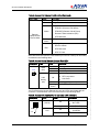
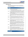
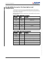
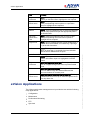
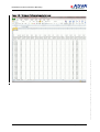
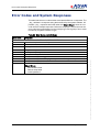
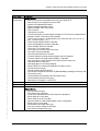
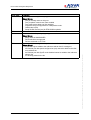
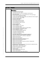
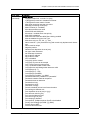
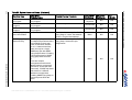
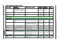
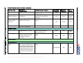
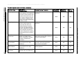
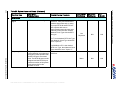
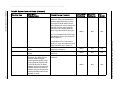
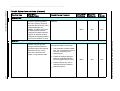
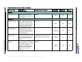
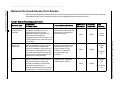
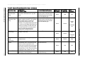
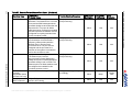
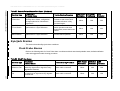
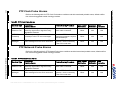
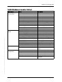
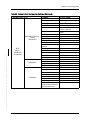
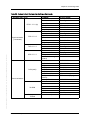
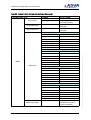
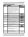
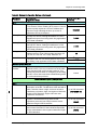
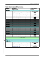
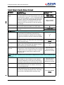
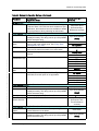
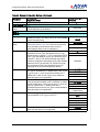
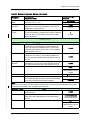
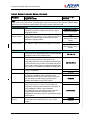
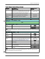
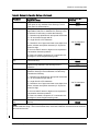
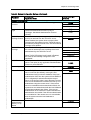
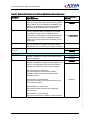
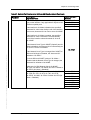
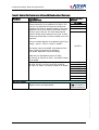
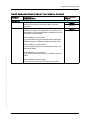
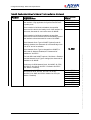
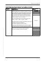
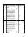
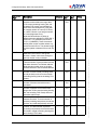
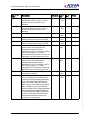
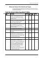
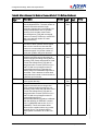
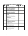
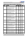
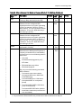
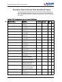
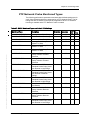
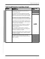
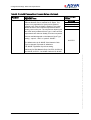
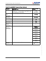
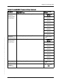
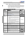
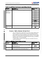
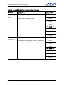
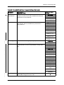
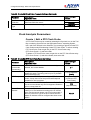
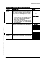
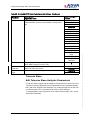
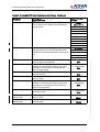
Error Code
Response
279
Invalid Loopback configuration: _why_
Where Why is:
(xxx) is currently active on this port
(xxx) Loopback cannot have Vlans enabled
(xxx) must have at least one Vlan enabled
Loopback config not supported for OAM passive mode.
OAM mode is (xxx)
Swap SA-DA must be (xxx) for EFM OAM Loopbacks
280
281
282
390
Data not available for _entityeid_: _why_
Where Why is:
Admin State is UNASSIGNED
PM Thresholds not supported
PM not monitored on CP Flow
Port _entityeid_ is not eligible to be put in selector reference list: _why_
Where Why is:
A port can only be added to the reference selector list if it is assigned
An Ethernet port with speed configured as (xxx) cannot be added to the reference selector list
An Ethernet port with SyncE mode disabled cannot be added to the reference
selector list
It is already present in the list
Installation and Operations Manual
FSP 150SP-100 R6.1.1 80000026364 Issue: A, © 2014 ADVA Optical Networking SE - Confidential
Error Codes and System Responses
Chapter 7 Alarms, Events and Probable Causes, Error Codes
Error Code
FSP 150SP-100 R6.1.1 80000026364 Issue: A, © 2014 ADVA Optical Networking SE - Confidential
512
Response
ATTRIBUTE SPECIFIC
Invalid value: _why_
Where Why is:
(xxx) already used by user (yyy)
(xxx) ARP route can be created
(xxx) can be set only for protocol belonging to protocol group
(xxx) cannot be set
(xxx) C-Tag Control option is not applicable when service type is (yyy)
(xxx) flow need to be MultiCOS enabled
(xxx) flow with UNTAGGED support need to have different COS level support
(xxx) has more than 1 Remote MEP
(xxx) has no Remote MEPs
(xxx) has non-zero EIR
(xxx) is already scheduled in (yyy)
(xxx) is currently active on this port
(xxx) is different than USM user (yyy)
(xxx) is not valid value
(xxx) is the last Superuser
(xxx) not available
(xxx) not available for (yyy) speed
(xxx) not supported by (yyy)
(xxx) not supported for Service Mode (yyy) (IPort Mode)
(xxx) not supported for UNTAGGED frames
(xxx) not supported on CP unit
(xxx) Out Of Range (xxx MIN...yyy MAX)
(xxx) requires valid address/mask
(xxx) speed not supported on (yyy)
(xxx) state is not supported
A port in the reference selector list cannot be unassigned
A Reference entity must Access, Network or BitsIn port
Address cannot be broadcast, multicast, or begin with 0.
Address cannot be (xxx)
Address cannot be broadcast
Address cannot be broadcast, mutlicast or all 0's.
Address cannot be experimental address
Address cannot be Loopback
Address cannot be loopback, broadcast, multicast, or begin with 0
Address cannot be multicast
Address cannot begin with 0
An Ethernet port in the reference selector list cannot be configured as (xxx)
Attribute missing - authentication key
Attribute missing - authentication protocol
Because Service type is in (xxx) mode
Bin index = (xxx) not in range
Cannot be empty
Cannot configure (xxx) loopback type
Cannot create (xxx) flow
Cannot create (xxx) flow with VLAN members
Installation and Operations Manual
391
Error Code
Response
512
(continued)
Where Why is:
Cannot enable QL Mode because the port configuration does not support SSM
Cannot enable QL Mode unless SyncE Mode is also enabled
Cannot enable SVlan on (xxx)
Cannot enable SyncE on a port with speed of 10Mbps
Cannot set Administrative State to Maintenance/Disabled
Cannot set name to empty string
Community (xxx) used by Target Parameter (yyy)
Component does not exist for (xxx)
Component ID - must be access port or network port
Current Network Clock Type does not support this QL value
Data TLV exceeds the allowed maximum of (xxx MIN... yyy MAX)
Delay must be (xxx MIN... yyy MAX)
DHCP client is enabled on (xxx)
DHCP server already enabled on other interface
Disposition cannot be set to (xxx)
Distrubution History Bin index = (xxx) not in range
Duplicate VLAN member (xxx) at positions (yyy) and (zzz)
Dying Gasp is already enabled for IP (xxx) on Target Address (yyy)
Empty string
Ether type can only be (0X88a8) or (0X8100)
Filename is empty
Filename must begin with digit or alphabet letter
Flows with UNTAGGED support need to be MultiCOS enabled
For TOS should not be higher than (xxx MAX)
Given IP address is not valid
Given IP mask is not valid
History Bin index = (xxx) not in valid range
ID (xxx) already used by (yyy)
ID must be 1
Illegal network mask (xxx)
In DHCP Server mode mask cannot be 255.255.255.254 and 255.255.255.255
Ingress PUSH PVID change disallowed
Inner VLAN Tag enabled without Outer VLAN Tag enabled
Interface must be eth0 or management tunnel interface
Invalid character
Invalid first character
Invalid character (xxx) at position (yyy)
Invalid engine ID - contains non-hex characters
Invalid engine ID - must be 12 octets long (first bit is 0)
Invalid engine ID - must be 5 to 32 octets long (first bit is 1)
Invalid engine ID - must be even number of octets
Invalid IP Address
Invalid port
Invalid Port Number
Invalid shelf state - state not supported
IP Addr Overlaps with other interface
IP is 0.0.0.0 for nexthop route
ipaddr: port format required
Key invalid or not strong enough
392
Installation and Operations Manual
FSP 150SP-100 R6.1.1 80000026364 Issue: A, © 2014 ADVA Optical Networking SE - Confidential
Error Codes and System Responses
FSP 150SP-100 R6.1.1 80000026364 Issue: A, © 2014 ADVA Optical Networking SE - Confidential
Chapter 7 Alarms, Events and Probable Causes, Error Codes
Error Code
Response
512
(continued)
Where Why is:
Length exceeds limit - must be 1 to (xxx)
LTM Egress ID must be in hexadecimal format
LTM Egress ID must contain 8 octets
Max value cannot be less than min value
Message processing model (xxx)
Metric must be (0… xxx MAX)
Min value exceeds max value
Mixed DOS and UNIX path
More than 1 enabled server has priority
Multi COS is disabled
Multi-COS flow must have N2A Rate Limiting enabled
Must be disabled for given Line Type
Must have only a-z, A-Z, 0-9, (.), - and _.
Name must be 1- (xxx) characters long and contain only alphanumeric characters
Name must be unique
Negative number
Network Port disposition is set to (xxx)
No upper case characters
No lowercase characters
Not a valid IP address
Not a valid IP mask
NTP is disabled
Only (xxx) can be created
Only (xxx) IP route can be created
Only 1 (xxx) Flow may exist on Port
Only 1 is allowed as MA COMP index
Only InService and Management states are valid
Out of Range (0...7)
Out of Range (1...100)
Out of Range (xxx MAX)
Out of Range (xxx MIN... yyy MAX)
Password cannot be “password” or “passw0rd”
Password contains character sequence
Password same as username
Password too long
Password too short
Pathname is empty
Periodic schedule cannot have forever duration
Port belongs to different unit.
Port disposition is set to (xxx) or (yyy)
Port does not exist for (xxx)
Port must be Network Port 1
Port service type is (xxx)
Port shaping is disabled
Port speed of 10 Mbps requires SyncE to be disabled
Priority Out Of Range (xxx MIN… yyy MAX)
Probe's Source MEP
Protocol cannot be none
Installation and Operations Manual
393
Error Code
Response
512
(continued)
Where Why is:
QL Mode is enabled; disable QL Mode first
ROLLOVER
Route to subnet/host (xxx) already exists
Sample time cannot be more than (xxx) Duration time
Sample time cannot be more than Duration time
Schedule list contains entity that is not a probe
Schedule list is empty
Schedule type conflicts with other attribute
Security Level of user (xxx) is (yyy)
Selected MEP destination type does not allow to specify ID
Selected MEP destination type does not allow to specify MAC address
Should be between (xxx MIN) and (yyy MAX) (inclusive)
Should be between (xxx MIN) and (yyy MAX) bytes (inclusive)
Should not be higher than (xxx MAX)
Source IP already in use by a Reflector
Source IP already used by a Probe
Source MEP does not exist
Source MEP should be an Up MEP
Specified IP address is already used by a Probe
Specified IP address is already used by another Reflector
Specified MAC address is invalid
Specified name is already in use (xxx) and (yyy)
Specified Source MEP is already used by (xxx)
Specified tag is invalid
Start Time in the past is not allowed
SyncE Mode cannot be disabled because this port is used in the reference
selector list
SysLog is disabled
Target Parameter (xxx) used by Target Address (yyy)
Too few digits
To few special characters
Too many consecutively repeated chars
Total provisioned CIR (xxx) bps exceeds port speed (yyy) bps
Total provisioned EIR (xxx) bps exceeds (yyy) bps
Traffic Management cannot be disabled
Tunnel already exists on (xxx)
Tunnel index must be from 1 to 255
Unknown interval
Unknown MEP destination type
Unknown Network Clock Type
Unknown priority map mode (xxx)
Unknown protocol type
Unknown/unsupported
Unsupported for given Line Type
Untagged support with (xxx)
Untagged support with (xxx) is disallowed
Username too long
Username too short
USM Security Name (xxx) used by Target Parameter (xxx)
394
Installation and Operations Manual
FSP 150SP-100 R6.1.1 80000026364 Issue: A, © 2014 ADVA Optical Networking SE - Confidential
Error Codes and System Responses
Chapter 7 Alarms, Events and Probable Causes, Error Codes
Error Code
Response
512
(continued)
Where Why is:
Value (xxx) out of range
Value (xxx) out of range (xxx MIN… yyy MAX)
Value must be NONE or PUSH
Value not supported for (xxx)
VLAN member cannot be specified as *-*
Vlan members are not supported for Service Mode (xxx)
VLAN member range must be of the form m:n-*, where (xxx)
VLAN members must have a single wild card value (xxx)
VLAN Tag is off but tag is specified
Vlan Tags not unique
Mandatory attribute missing.
Attribute cannot be set.
Attribute not supported
Attribute value (xxx) not supported
Invalid MAC address.
Invalid VLAN tag.
Invalid password: _why_
Where Why is:
Key invalid or not strong enough
Password is same as username
Invalid IP Address.
Invalid Network Mask.
Outer VLAN Tag Control must be enabled to enable Inner VLAN Tag Control.
_entityname_ does not exist.
Attribute not applicable _why_
Where Why is:
Management Traffic Bridging is enabled
Network mask is not applicable for PPP
DHCP is not applicable for PPP
RIPv2 is not applicable for PPP
FSP 150SP-100 R6.1.1 80000026364 Issue: A, © 2014 ADVA Optical Networking SE - Confidential
513
514
515
516
517
518
519
520
521
522
523
524
Installation and Operations Manual
395
Error Code
Response
768
773
775
780
781
784
785
794
795
796
797
798
799
800
801
802
803
804
805
806
807
808
809
810
811
812
813
814
815
816
817
818
819
820
821
822
823
824
825
826
827
828
SPECIAL CONDITIONS
Card _cardeid_ not present.
Invalid Loopback Configuration Type.
Resource in Use by Loopback.
Timed loopback with Vlan tag enabled.
Non-Vlan loopback with Vlan tag enabled.
Loopback is not active.
Loopback already exists.
Invalid test config.
Port Not in Auto Negotiation.
Linktrace is currently active
Loopback is currently active
Maximum active linktrace sessions reached
Maximum active loopback sessions reached
Port media is invalid.
Operation is not supported.
No Linktrace Reply found.
Interface not configured.
Route to Host/Subnetwork already exists.
Invalid Gateway IP Address.
Invalid Route Type.
Invalid SWDL message
Backup file is locked
Invalid backup type
Database has not been backed up
Backup directory is empty
Failed to archive files
Failed to unarchive files
Failed to read directory
Transfer in progress
Transfer not in progress
File Transfer Server Type not supported
User id not set
Remote host not set
Remote file not set
Local file not set
File Name not set
Protocol not set
Unsupported protocol
Transfer protocol has been disabled
Invalid url
Transfer canceled
Unable to access local file
396
FSP 150SP-100 R6.1.1 80000026364 Issue: A, © 2014 ADVA Optical Networking SE - Confidential
Error Codes and System Responses
Installation and Operations Manual
FSP 150SP-100 R6.1.1 80000026364 Issue: A, © 2014 ADVA Optical Networking SE - Confidential
Chapter 7 Alarms, Events and Probable Causes, Error Codes
Error Code
Response
829
830
831
832
833
834
835
836
837
838
839
840
841
842
843
844
845
846
847
848
849
850
851
852
853
854
855
856
857
858
Transfer execute failed
Error string returned
Bad archive file
Error syncing with scu
Error processing topology change event
SCU push failed
Flash erase failed
Flash partition sync failed
Install Failed
Activate Failed
Cancel Activate Failed
Validate Failed
Revert Failed
Operation not allowed in current state
Invalid Validation Time
Invalid Reboot Time
Operation not allowed: Database upload in progress
Operation not allowed: Database download in progress
Operation not allowed: Database backup in progress
Operation not allowed: Database restore in progress
Operation not allowed: Software download in progress
Operation not allowed: Software install in progress
Operation not allowed: Software upgrade in progress
Operation not allowed: Software validate in progress
Operation not allowed: Software cancel-upgrade in progress
Operation not allowed: Software revert in progress
Operation not allowed: System rebooting
Operation not allowed: System software being upgraded
Software is incompatible for Network Element
Sysdefdb directory is empty
RESOURCE ERRORS
Exhausted Total Number of Policers.
Exhausted Total Number of Queues.
Exhausted Total Number of Memory Segments.
Exhausted Total Number of VLAN Lookups.
Exhausted Total Number of EVC Lookups.
Insufficient bandwidth for CIR/EIR settings.
Rules check failed.
Rules check failed: (_errstr_).
SOFTWARE RELATED
Invalid message qualifier.
Resource is busy.
1024
1025
1026
1027
1028
1029
1280
1281
4096
4097
Installation and Operations Manual
397
Error Code
Response
4098
Database operation failed: _why_
Where Why is:
Db State is not ok
Can't reopen System Default Db
Build Shadow Tree failed
Loading data from database failed.
User transaction does not exist.
User transaction has not been validated.
Request has been timed out.
Transaction id is 0.
Cannot get global system data.
Invalid application event.
No FROM port found for NE.
Configfile operation failed.
Loading data from configfile failed: _why_
Where Why is:
Can't open configfile
_configFileName_failed_command
Init load failed
Login failed
MEIATTR_TIMING_SOURCE
MEIATTR_MAX_SLAVE_SUPPORTED
MEIATTR_MAX_STATIC_SLAVE_SUPPORTED
MEIATTR_SLAVE_ANNOUNCE_MSG_RATE
MEIATTR_SLAVE_SYNC_MSG_RATE
MEIATTR_SLAVE_DELAY_RESP_MSG_RATE
MEIATTR_ALIAS_ERROR
MEIATTR_TIME_CLOCK_EID
MEIATTR_TIMEREF
MEIATTR_SYNC_OPER_TYPE
MEIATTR_SYNC_REF_REQ
MEIATTR_SYNC_DOMAIN
MEIATTR_SELECTION_MODE
Invalid message received
Invalid user
Unable to update profile
Internal error
Internal error
Internal error - IPC
Internal error
Internal error - EP
Invalid user name received
insufficient privilege level
SNMP SPECIFIC
Attribute is deprecated
4099
4100
4101
4102
4103
4104
4105
4106
4107
4108
8000
8001
8002
8003
8004
8005
8006
8007
8008
8009
8010
8011
8012
8192
8193
8194
8195
8196
8197
8198
8199
8200
8201
20480
398
FSP 150SP-100 R6.1.1 80000026364 Issue: A, © 2014 ADVA Optical Networking SE - Confidential
Error Codes and System Responses
Installation and Operations Manual
Chapter 7 Alarms, Events and Probable Causes, Error Codes
Error Code
Response
20481
20482
VLAN ID is not specified
Invalid Data for Cable Length Benchmark, Required format xx.yy
Alarm Attributes, Probable Cause and
Trouble Clearing
All problems causing an alarm event are soaked for 2.5 seconds before the
alarm indication is raised. The problem causing the alarm event must clear for
10 seconds before the alarm indication is cleared. All FSP 150SP System
alarms and default notification codes are shown in Table 28 on p. 401. For all
FSP 150SP Access and Network alarms, see Table 31 on p. 417. For Maintenance End Point (MEP) alarms, see Table 5-21. Each of the following tables
contain a description of the alarm condition, probable cause and suggested
trouble clearing procedure. To clear alarm conditions, it is suggested that you
start by using the trouble clearing procedure in “Recommended Steps for Trouble Clearing” on p. 381.
FSP 150SP-100 R6.1.1 80000026364 Issue: A, © 2014 ADVA Optical Networking SE - Confidential
Alarm Profile Notification Codes
The user has the ability to retrieve and edit alarm profile Notification Codes. To
modify alarm Notification Codes for a given alarm condition type using eVision,
select Maintenance view, right click on the desired entity in the Selection Tree
and select Edit Alarm Attributes. The options available for notification codes are:
Critical, Major, Minor, Not Alarmed or Not Reported. For LED locations associated with an alarm condition, refer to “Connector and LED Descriptions” on
p. 65. Valid Notification Codes are provided in the following table.
Table 27: Alarm Profile Notification Codes
Notification
Code
CR
MJ
MN
NA
NR
CR
Installation and Operations Manual
Description
Critical - A severe, service-affecting condition has occurred
and that immediate corrective action is imperative.
Major - A serious disruption of service or a malfunction or
failure of an important system function.
Minor - Trouble that does not have a serious effect on service
to customers or for trouble in functions that are not essential
to the NE operation.
Not Alarmed - A condition that is reported only as an event
and can be retrieved from the system.
Not Reported - A condition that is not reported but can be
retrieved from the system.
Clear - This value can not be used in an alarm profile. Used
with event reporting only.
399
Alarm Attributes, Probable Cause and Trouble Clearing
Alarms and Events
Refer to the following table for system alarm conditions and their associated
probable cause, default Notification Code and suggested trouble clearing procedure. System components include the following subsystems:
System
•
NTESP100 Card
•
NTESP100 Shelf
•
Synchronization
•
Precision Time Protocol (PTP) Alarms
•
Network Port and Access Port Alarms
•
Alarm Masking
FSP 150SP-100 R6.1.1 80000026364 Issue: A, © 2014 ADVA Optical Networking SE - Confidential
•
400
Installation and Operations Manual
FSP 150SP-100 R6.1.1 80000026364 Issue: A, © 2014 ADVA Optical Networking SE - Confidential
Installation and Operations Manual
Table 28: System Alarms and Events
Condition Type
Description /
Probable Cause
Trouble Clearing Procedure
NSA Default
Notification
SA Default
Notification
LED
Indication
System
Primary NTP Server
Failed
IP Address Conflict
401
Data Base - File
Transfer In Progress
SWDL - File Transfer
In Progress
a) Target IP address
connectivity or routing problem.
b) No NTP server / NTP server
down.
Attempt to connect to the
Backup NTP Server failed.1
a) Target IP address
connectivity or routing problem.
b) No NTP server / NTP server
down.
IP Address Conflict (declared
when a DHCP assigned
address overlaps with an
existing subnet)
Database file transfer is in
progress.
Software Download file transfer
is in progress.
1) Verify that the IP address can be
reached (respond to pings) by
performing both a ping and a trace
route from the management tunnel’s
IP address.
2) Verify management
communication configuration.
a) Repair IP address connectivity or
routing problem.
b) Switch to Backup NTP Server.
Repair NTP server.
1) Verify that the IP address can be
reached (respond to pings) by
performing both a ping and a trace
route from the management tunnel’s
IP address.
2) Verify management
communication configuration.
a) Repair IP address connectivity or
routing problem.
b) Switch to Primary NTP Server.
Repair NTP server.
Verify management communication
configuration.
No action required.
No action required.
Minor
N/A
N/A
Minor
N/A
N/A
N/A
CR
N/A
N/A
N/A
N/A
N/A
Not
Reported
Not
Reported
Chapter 7 Alarms, Events and Probable Causes, Error Codes
Backup NTP Server
Failed
Attempt to connect to the
Primary NTP Server failed.1
Condition Type
Description /
Probable Cause
Installation and Operations Manual
SWDL - Installation
In Progress
SWDL - Activation In
Progress
SWDL - Validation In
Progress
SNMP Dying Gasp Host Unreachable
Software Download installation
is in progress.
Software Download activation
is in progress.
Software Download validation
is in progress.
Database or Network issue.
SNMP Dying Gasp Resource Busy
SNMP Dying Gasp is enabled
on multiple trap hosts and there
is reachability to these trap
hosts via the same interface.
On a 1+1 Network Interface,
there can only be a single
SNMP trap host with SNMP
Dying Gasp Enabled. Enabling
a second trap host for SNMP
dying gasp raises the alarm.
or
There are multiple
management tunnels active
(Network side is unprotected
with tunnel, Access side also
has tunnel). 2 SNMP trap hosts
that resolve to 2 different
interfaces are supported.
Enabling SNMP Dying Gasp on
a third trap host raises the
alarm.
Trouble Clearing Procedure
No action required.
No action required.
No action required.
Check database settings for SNMP
Dying Gasp. If correct, test network
access - Ping the Host address.
Check database settings for SNMP
Dying Gasp. Delete extra port
assignments.
FSP 150SP-100 R6.1.1 80000026364 Issue: A, © 2014 ADVA Optical Networking SE - Confidential
NSA Default
Notification
SA Default
Notification
LED
Indication
Not
Reported
N/A
N/A
Not Alarmed
N/A
N/A
Not Alarmed
N/A
N/A
Minor
N/A
N/A
Minor
N/A
N/A
Alarm Attributes, Probable Cause and Trouble Clearing
402
Table 28: System Alarms and Events (Continued)
FSP 150SP-100 R6.1.1 80000026364 Issue: A, © 2014 ADVA Optical Networking SE - Confidential
Installation and Operations Manual
Table 28: System Alarms and Events (Continued)
Condition Type
DB Downgrade
File Transfer In
Progress
Operation In
Progress
Network Element
3G USB Modem
Link Down
Modem is not
qualified
Modem Removed
DCN Port
Link Down
NTESP100 Card
Communication
Failure
Trouble Clearing Procedure
SA Default
Notification
LED
Indication
No Action Required
Database Downgrade implementation of a database
file below the current release
level.
File transfer is in progress.
No action required.
Operation is in progress.
No action required.
Link Down is generated when a
physical connection is lost on
the port.
No SIM card is detected.
Perform an Etherjack Diagnostic test.
Repair the port using test results.
The modem is not qualified by
ADVA Optical Networking.
3G modem is removed from the
USB port.
NSA Default
Notification
Not
Reported
Unplug the 3G modem, insert the
SIM card into the modem, and
re-insert the 3G modem into the USB
port.
Install an ADVA Optical Networking
qualified 3G modem.
Re-insert ADVA Optical Networking
qualified 3G modem.
N/A
N/A
N/A
N/A
N/A
N/A
Not Alarmed
N/A
N/A
Not Alarmed
N/A
N/A
Not Alarmed
N/A
N/A
Not Alarmed
N/A
N/A
Not
Reported
Not
Reported
Cable disconnected, cable
fault, improper configuration.
Check physical cabling, MDIX is not
supported on DCN port. Check
settings on system to match DCN
network requirements.
Not Alarmed
Not Alarmed
N/A
Communication Failure
Equipment is malfunctioning. Repair
or replace unit.
Minor
N/A
N/A
403
Chapter 7 Alarms, Events and Probable Causes, Error Codes
No SIM Card
Description /
Probable Cause
Condition Type
Description /
Probable Cause
Equipment Fault
Equipment fault found.
Equipment Does Not
Match Provisioning
Equipment does not match the
provisioning.
Equipment
Provisioned But
Removed
Equipment is provisioned but
equipment is removed.
Test Alarm
A test alarm is generated to
check alarm propagation.
Ensure alarm propagates properly.
Equipment has exceeded the
temperature limit (>= 90 C).
Check ambient temperature and
adjust. Verify that airflow
requirements are met.
Check ambient temperature and
adjust.
NTESP100 Shelf
Over Temperature
Under Temperature
System temperature has
dropped below the minimum
temperature threshold
(<= -50 C).
Trouble Clearing Procedure
Equipment is malfunctioning. Repair
or replace unit.
Verify the provisioning against the
equipment. Re-provision as
necessary.
Replace equipment or place out of
service.
NSA Default
Notification
SA Default
Notification
LED
Indication
Status
Red
Status
Blinking
Red
N/A
Critical
N/A
Critical
N/A
Critical
N/A
Major
N/A
N/A
Minor
N/A
Status
Red
Minor
N/A
Status
Red
Not Alarmed
N/A
N/A
Synchronization
Installation and Operations Manual
10MHz (CLK) Port
Sync Reference
Failed
Sync Reference Failed. This
alarm reported when the CLK
port is used as system Synchronization input. The port must be
assigned and the port must be
a member of the system clock
selector list for this condition to
exist.
Ensure that the CLK cable is connected.
FSP 150SP-100 R6.1.1 80000026364 Issue: A, © 2014 ADVA Optical Networking SE - Confidential
Alarm Attributes, Probable Cause and Trouble Clearing
404
Table 28: System Alarms and Events (Continued)
FSP 150SP-100 R6.1.1 80000026364 Issue: A, © 2014 ADVA Optical Networking SE - Confidential
Installation and Operations Manual
Table 28: System Alarms and Events (Continued)
Condition Type
Frequency Offset
Output Squelch
Sync Reference
Forced Switch
Sync Reference
Manual Switch
Sync Reference Wait
To Restore
Frequency Offset. The
synchronization circuit detected
a frequency offset problem with
the port's recovered clock. The
port must be assigned and the
port must be a member of the
system clock selector list for this
condition to exist.
The port is squelched due to
the port's output signal QL
being lower than the port's
configured Squelch attribute.
The port's QL Mode attribute
must be configured as enabled
and the Squelch QL attribute
must be configured as anything
besides None for this condition
to exist.
A Sync Reference has been
locked out. Usually due to
failure, configuration changes
planned or maintenance
operations.
A forced switch operation has
been performed on a Sync
Reference.
A manual switch operation has
been performed on a Sync
Reference.
A Sync Reference has been
restored and is in WTR timing.
Trouble Clearing Procedure
NSA Default
Notification
SA Default
Notification
LED
Indication
Verify and troubleshoot clock
reference.
Minor
N/A
N/A
Minor
N/A
N/A
Minor
N/A
N/A
Minor
N/A
N/A
Minor
N/A
N/A
Minor
N/A
N/A
Verify and troubleshoot clock
reference.
Test the Locked Out Sync Reference
and remove lock out when reference
is fully functional again.
Evaluate reason for forced switch
operation and when appropriate,
remove the forced switch.
Evaluate reason for the manual
switch operation.
No Action Required.
405
Chapter 7 Alarms, Events and Probable Causes, Error Codes
Sync Reference
Locked Out
Description /
Probable Cause
Condition Type
Description /
Probable Cause
BITS In Port
Alarm Indication
Signal
BITS Alarm Indication Signal.
Trouble Clearing Procedure
Verify and troubleshoot clock
reference. Verify and troubleshoot
possible signal mismatch. In order
for proper BITS-IN and BITS-OUT
inter-operate with source
equipment/test sets, the user must
manually match the FSP 150SP's
Network Clock Type with the BITS
line type.
NSA Default
Notification
SA Default
Notification
LED
Indication
Not
Reported
N/A
N/A
Minor
N/A
N/A
If a T1 is the desired BITS Line Type,
then Network Clock Type should be
set to "Option 2".
Frequency Offset
Installation and Operations Manual
Frequency Offset. The
synchronization circuit detected
a frequency offset problem with
the BITS-IN port's recovered
clock. The BITS-IN port must be
assigned and the BITS-IN port
must be a member of the system
clock selector list for this
condition to exist.
If a 2048kHz or E1 is the desired
BITS Line Type, then Network Clock
Type should be set to "Option 1".
Verify and troubleshoot clock
reference.
FSP 150SP-100 R6.1.1 80000026364 Issue: A, © 2014 ADVA Optical Networking SE - Confidential
Alarm Attributes, Probable Cause and Trouble Clearing
406
Table 28: System Alarms and Events (Continued)
FSP 150SP-100 R6.1.1 80000026364 Issue: A, © 2014 ADVA Optical Networking SE - Confidential
Installation and Operations Manual
Table 28: System Alarms and Events (Continued)
Condition Type
Description /
Probable Cause
Loss of Frame
BITS Loss of Frame
Trouble Clearing Procedure
Verify and troubleshoot clock
reference. Verify and troubleshoot
possible signal mismatch. In order
for proper BITS-IN and BITS-OUT
inter-operate with source equipment/
test sets, the user must manually
match the FSP 150SP's Network
Clock Type with the BITS line type.
NSA Default
Notification
SA Default
Notification
LED
Indication
Minor
N/A
N/A
Minor
N/A
N/A
Minor
N/A
N/A
Minor
N/A
N/A
If a T1 is the desired BITS Line Type,
then Network Clock Type should be
set to "Option 2".
Sync QL Invalid
Sync QL Mismatch
BITS Loss of Signal. BITs signal
is lost.
Synchronization Quality Level
Invalid.
Synchronization Quality Level
Mismatch. The BITS-IN port
receives SSM messages
whose specified Quality Level
is lower than the Expected QL.
The BITS-IN port's QL Mode
attribute must be configured as
enabled and the Expected QL
attribute must be configured as
anything besides None for this
condition to exist.
407
Chapter 7 Alarms, Events and Probable Causes, Error Codes
Loss of Signal
If a 2048kHz or E1 is the desired
BITS Line Type, then Network Clock
Type should be set to "Option 1".
Verify and troubleshoot clock
reference connection.
Verify and troubleshoot clock
reference.
Verify and troubleshoot clock
reference.
Condition Type
Sync Reference
Failed
Sync Reference Wait
To Restore
Sync Reference
Locked Out
Sync Reference
Forced Switch
Sync Reference
Manual Switch
Description /
Probable Cause
Installation and Operations Manual
Synchronization Referencing
Failed. The BITS-IN port has
failed in such a way that its
clock cannot be recovered, thus
preventing it from being used
as a synchronization reference
(e.g., LOS). The BITS-IN port
must be assigned for this
condition primitive to exist.
A Sync Reference has been
restored and is in WTR timing.
A Sync Reference has been
locked out. Usually due to
failure, configuration changes
planned or maintenance
operations.
A forced switch operation has
been performed on a Sync
Reference.
A manual switch operation has
been performed on a Sync
Reference.
Trouble Clearing Procedure
NSA Default
Notification
SA Default
Notification
LED
Indication
Verify and troubleshoot clock
reference.
No Action Required.
Test the Locked Out Sync Reference
and remove lock out when reference
is fully functional again.
Evaluate reason for forced switch
operation and when appropriate,
remove the forced switch.
Evaluate reason for the manual
switch operation.
FSP 150SP-100 R6.1.1 80000026364 Issue: A, © 2014 ADVA Optical Networking SE - Confidential
Minor
N/A
N/A
Minor
N/A
N/A
Minor
N/A
N/A
Minor
N/A
N/A
Minor
N/A
N/A
Alarm Attributes, Probable Cause and Trouble Clearing
408
Table 28: System Alarms and Events (Continued)
FSP 150SP-100 R6.1.1 80000026364 Issue: A, © 2014 ADVA Optical Networking SE - Confidential
Installation and Operations Manual
Table 28: System Alarms and Events (Continued)
Condition Type
BITS Out Port
Output Squelch
Description /
Probable Cause
Trouble Clearing Procedure
Verify and troubleshoot clock
reference.
GPS Antenna Fail. This
condition may be reported
during normal GPS Receiver
operation when active antenna
draws less current, in such
cases like connection with
splitter or long antenna cable.
Ignore if Operational state is Normal.
SA Default
Notification
LED
Indication
Minor
N/A
N/A
Minor
N/A
N/A
GPS Port
GPS Antenna Fail
If operational state is not Normal:
•
Check number of tracked Satellites. If 0: check antenna cable is
securely connected to the
antenna input.
•
Ensure the antenna required
power is compatible with the
SP-100 supplied power (3.3V).
•
Ensure sufficient sky view is
available above the antenna.
•
Replace antenna.
409
Chapter 7 Alarms, Events and Probable Causes, Error Codes
Quality Level Squelch. The
BITS-OUT port is squelched
due to the system's QL being
lower than the BITS-OUT port's
configured Squelch QL
attribute. The BITS-OUT port's
QL Mode attribute must be
configured as enabled and the
Squelch QL attribute must be
configured as anything besides
None for this condition to exist.
NSA Default
Notification
Condition Type
PPS Port
Output Squelch
SYNC-1-1-1
All Input Sync
Referenced Failed
Sys Clock Mode Fast Acquisition
Sys Clock Mode Freerunning
Installation and Operations Manual
Sys Clock Mode Holdover
Description /
Probable Cause
Trouble Clearing Procedure
Output of the PPS port has been
squelched due to change of
state of the entity serving as the
port's source.
Verify and troubleshoot PPS port
source.
All synchronization references
in the system clock selector list
have failed. The system clock
selector list must have at least
one member in order for this
condition primitive to exist.
System Clock Mode - Fast
Acquisition Synchronization.
This indicates the clock selector
is acquiring the phase of the
selected reference.
System Clock Mode - Free
Running Synchronization. This
indicates the internal oscillator
is the source of the system
clock.
System Clock Mode - Holdover
Synchronization. This indicates
the selected reference is invalid
and no other valid input
reference is available and the
system clock has previously
locked to the now invalid
reference.
Verify and troubleshoot clock
reference.
NSA Default
Notification
SA Default
Notification
LED
Indication
Minor
N/A
N/A
Major
N/A
N/A
Not
Reported
N/A
N/A
Not
Reported
N/A
N/A
Not
Reported
N/A
N/A
No action necessary.
Verify synchronization provisioning
to ensure option is set correctly.
Otherwise, no action is necessary.
Verify and troubleshoot clock
reference.
FSP 150SP-100 R6.1.1 80000026364 Issue: A, © 2014 ADVA Optical Networking SE - Confidential
Alarm Attributes, Probable Cause and Trouble Clearing
410
Table 28: System Alarms and Events (Continued)
FSP 150SP-100 R6.1.1 80000026364 Issue: A, © 2014 ADVA Optical Networking SE - Confidential
Installation and Operations Manual
Table 28: System Alarms and Events (Continued)
Condition Type
Sys Clock Mode Loss of Lock
Average Holdover
Frequency Not
Ready
Time Reference
Locked Out
Time Reference
Unavailable
Time Reference
Degraded
Time Reference
Unavailable WTR
System Clock Mode - Loss of
Lock. This indicates the
selected reference had locked
and is not invalid and the lock
has been lost. While in this
state, the clock selector will be
attempting to acquire the phase
of the selected reference.
Clock was not synced long
enough to enter holdover and is
now freerunning.
Sync-1-1-1 provisioned as Time
Reference of Time Clock and
has been Locked out.
Sync-1-1-1 provisioned as Time
Reference of Time Clock and
Force Switch has been applied.
Sync-1-1-1 provisioned as Time
Reference of Time Clock and
Unavailable to serve as valid
reference.
Sync-1-1-1 provisioned as Time
Reference of Time Clock and
can't provide valid TOD. This
condition is persistently
reported.
Sync-1-1-1 provisioned as Time
Reference of Time Clock and is
recovery process from
Unavailable condition.
Trouble Clearing Procedure
NSA Default
Notification
SA Default
Notification
LED
Indication
Verify and troubleshoot clock
reference.
No action necessary.
Test the Locked Out Time Reference
and remove lock out when reference
is fully functional again.
Evaluate reason for forced switch
operation and when appropriate,
remove the forced switch.
Check Sync-1-1-1 Sync References,
ensure that Sync-1-1-1 Operational
state is "Normal" and Clock Mode is
"Locked".
N/A
Not
Reported
N/A
N/A
Not
Reported
N/A
N/A
Minor
N/A
N/A
Minor
N/A
N/A
Minor
N/A
N/A
Minor
N/A
N/A
Minor
N/A
N/A
N/A
411
Chapter 7 Alarms, Events and Probable Causes, Error Codes
Time Reference
Forced Switch
Description /
Probable Cause
Condition Type
Time Reference
Degraded WTR
Time Clock
Time Clock Not
Locked
Time Frequency
Lock
Time Frequency Not
Traceable
Time Holdover
Description /
Probable Cause
Trouble Clearing Procedure
Sync-1-1-1 provisioned as Time
Reference of Time Clock and in
the recovery process from
Degraded condition. Note: this
condition is never reported for
Sync-1-1-1.
N/A
Time Reference Locked Out.
N/A
Installation and Operations Manual
Time Clock Time Traceability
status is Time Freq Lock.
Time Clock Frequency Traceability status is Not Traceable.
Time Clock Time Traceability
status is Holdover.
Time Not Traceable
Time Clock Time Traceability
status is Not Traceable.
Time Of Day (TOD) Port
Output Squelch
Output of the TOD port has
been squelched due to change
of state of the entity serving as
the port's source.
N/A
N/A
N/A
N/A
Verify and troubleshoot TOD port
source.
NSA Default
Notification
SA Default
Notification
LED
Indication
Minor
N/A
N/A
Minor
N/A
N/A
Minor
N/A
N/A
Minor
N/A
N/A
Minor
N/A
N/A
Minor
N/A
N/A
Minor
N/A
N/A
1. When using Ethernet encapsulated management tunnels, the source IP address of the ping used to validate reachability of the trap
host is the IP address assigned to the management tunnel, and not the system IP address.
FSP 150SP-100 R6.1.1 80000026364 Issue: A, © 2014 ADVA Optical Networking SE - Confidential
Alarm Attributes, Probable Cause and Trouble Clearing
412
Table 28: System Alarms and Events (Continued)
FSP 150SP-100 R6.1.1 80000026364 Issue: A, © 2014 ADVA Optical Networking SE - Confidential
Installation and Operations Manual
Precision Time Protocol (PTP) Alarms
This section describes Precision Time Protocol (PTP) alarm conditions.
SOOC Alarms
Refer to the following table for PTP Slave-Only Ordinary Clocks (SOOC) alarm conditions and their associated probable
cause, default notification code and suggested trouble clearing procedure.
Table 29: SOOC Alarms
Condition Type
PTSF - Loss
Sync
PTSF Unusable
Packet Timing Signal Fail - Loss of Synchronization. A Sync/Followup is not
received before syncReceiptTimeout or
Delay Response is not received before delRespReceiptTimeout.
A loopback on the port on which the PTP
Flowpoint of the SOOC exists will result in a
PTSF - Loss of Sync.
Packet Timing Signal Fail - Loss Announce.
Announce is not received before
announceReceiptTimeout.
A loopback on the port on which the PTP
Flowpoint of the SOOC exists will result in a
PTSF - Loss Announce.
Packet Timing Signal Fail - Unusable. The
PTP packet stream is not usable for clock
recovery. For example, unable to recover
clock due to unacceptable PTP packet
PDV.
Trouble Clearing Procedure
NSA Default
Notification
SA Default
Notification
LED
Indication
Minor
N/A
N/A
Minor
N/A
N/A
Minor
N/A
N/A
a) Verify and troubleshoot
clock reference.
b) Release loopback.
a) Verify and troubleshoot
clock reference.
b) Release loopback.
Verify and troubleshoot clock
reference.
413
Chapter 7 Alarms, Events and Probable Causes, Error Codes
PTSF - Loss
Announce
Description /
Probable Cause
Refer to the following table for PTP Telecom Slave alarm conditions and their associated probable cause, default notification code and suggested trouble clearing procedure.
Table 30: Telecom Slave Alarms
Condition Type
Sync Reference
Failed
Sync QL
Mismatch
Frequency
Offset
Installation and Operations Manual
Sync QL Invalid
Sync Reference
Locked Out
Description /
Probable Cause
Synchronization Referencing Failed. The
TS has failed in such a way that its clock
cannot be recovered, thus preventing it
from being used as a synchronization
reference. The TS must be assigned for this
condition primitive to exist.
Synchronization Quality Level Mismatch.
The TS receives SSM messages whose
specified Quality Level is lower than the
Expected QL. The TS's QL Mode attribute
must be configured as enabled and the
Expected QL attribute must be configured
as anything besides None for this condition
to exist.
Frequency Offset. The synchronization
circuit detected a frequency offset problem
with the TS's recovered clock. The TS must
be assigned and the TS must be a member
of the system clock selector list for this
condition to exist.
Synchronization Quality Level Invalid.
A Sync Reference has been locked out.
Usually due to failure, configuration
changes planned or maintenance
operations.
Trouble Clearing Procedure
NSA Default
Notification
SA Default
Notification
LED
Indication
Minor
N/A
N/A
Minor
N/A
N/A
Minor
N/A
N/A
Minor
N/A
N/A
Minor
N/A
N/A
Verify and troubleshoot clock
reference.
Verify and troubleshoot clock
reference.
Verify and troubleshoot clock
reference.
Verify and troubleshoot clock
reference.
Test the Locked Out Sync
Reference and remove lock
out when reference is fully
functional again.
FSP 150SP-100 R6.1.1 80000026364 Issue: A, © 2014 ADVA Optical Networking SE - Confidential
Alarm Attributes, Probable Cause and Trouble Clearing
414
Telecom Slave Alarms
FSP 150SP-100 R6.1.1 80000026364 Issue: A, © 2014 ADVA Optical Networking SE - Confidential
Installation and Operations Manual
Table 30: Telecom Slave Alarms (Continued)
Description /
Probable Cause
Sync Reference
Forced Switch
A forced switch operation has been
performed on a Sync Reference.
Sync Reference
Manual Switch
A manual switch operation has been
performed on a Sync Reference.
Sync Reference
Wait To Restore
All SOOCs
Failed
A Sync Reference has been restored and is
in WTR timing.
All Slave-Only Ordinary Clocks (SOOC)
failed. The OC-S Virtual Port in a Faulty
state or a PTSF Alarm exists on the SOOC.
Telecom Slave in Freerun. The recovered
clock is the same as the internal oscillator
and the Telecom Slave is in freerun.
Telecom Slave in Holdover. The recovered
clock is in holdover as there is no valid
SOOC to support clock recovery.
SyncJack is not locked to a reference time
source.
SyncJack is not locked to a reference
frequency source.
Telecom Slave provisioned as Time Reference for the Time Clock and has been
locked out.
Telecom Slave provisioned as Time Reference for the Time Clock and has been
Forced.
Telecom Slave
in Freerun
Telecom Slave
in Holdover
SJ No Time
Lock
SJ No
Frequency Lock
Time Reference
Locked Out
Time Reference
Forced Switch
NSA Default
Notification
SA Default
Notification
Minor
N/A
N/A
Minor
N/A
N/A
Minor
N/A
N/A
Verify and troubleshoot clock
reference.
N/A
Critical
N/A
Verify and troubleshoot clock
reference and provisioning.
NR
N/A
N/A
Verify and troubleshoot clock
reference and provisioning.
NR
N/A
N/A
N/A
Major
N/A
N/A
Major
N/A
Minor
N/A
N/A
Minor
N/A
N/A
Trouble Clearing Procedure
Evaluate reason for forced
switch operation and when
appropriate, remove the forced
switch.
Evaluate reason for the
manual switch operation.
No Action Required.
Verify and troubleshoot clock
reference and provisioning.
Verify and troubleshoot clock
reference and provisioning.
N/A
LED
Indication
N/A
415
Chapter 7 Alarms, Events and Probable Causes, Error Codes
Condition Type
Condition Type
Description /
Probable Cause
Time Reference
Unavailable
Telecom Slave provisioned as Time Reference for the Time Clock and Unavailable.
Time Reference
Degraded
Installation and Operations Manual
Telecom Slave
in Time Freerun
Telecom Slave
in Time
Holdover
Time Reference
Unavailable
WTR
Time Reference
Degraded WTR
Trouble Clearing Procedure
Telecom Slave is not locked to TOD.
Check the Telecom Slave Frequency traceability status
(Syncjack clock analysis is
required). If Syncjack is not
available, check the Telecom
Slave Frequency Recovery
state.
Check the Telecom Slave
Time traceability status (Syncjack clock analysis is required).
If Syncjack is not available,
check the Telecom Slave
Phase Recovery state.
N/A
Telecom slave time recovery is in Holdover.
N/A
Telecom Slave provisioned as Time Reference for the Time Clock and can't provide
valid TOD.
Telecom Slave provisioned as Time Reference for the Time Clock and is in recovery
process from Unavailable condition.
Telecom Slave provisioned as Time Reference for the Time Clock and is in recovery
process from Degraded condition.
NSA Default
Notification
SA Default
Notification
LED
Indication
Minor
N/A
N/A
Minor
N/A
N/A
Minor
N/A
N/A
NR
N/A
N/A
Minor
N/A
N/A
Minor
N/A
N/A
N/A
N/A
FSP 150SP-100 R6.1.1 80000026364 Issue: A, © 2014 ADVA Optical Networking SE - Confidential
Alarm Attributes, Probable Cause and Trouble Clearing
416
Table 30: Telecom Slave Alarms (Continued)
FSP 150SP-100 R6.1.1 80000026364 Issue: A, © 2014 ADVA Optical Networking SE - Confidential
Installation and Operations Manual
Network Port and Access Port Alarms
Refer to the following table for Network Port and Access Port (including Line Card Access Port) alarm conditions and their
associated probable cause, default notification code and suggested trouble clearing procedure.
Table 31: Network Port and Access Port Alarms
Condition Type
Duplex Mode of
Far End Device
Unknown
Link Down - Cable
Fault
Duplex mode of the connected
equipment is unknown. The unit
determined it cannot conclude
negotiation with remote end on the
Ethernet port. Although auto
negotiation failure is a minor alarm, it is
usually followed by a critical alarm due
to link down.
Link Down is generated when a
physical connection is lost on a good
link on the Ethernet interface port
(Access or Network). Upon the loss of
connection on a given port, this is the
first notification being sent, before any
specific cause is determined (such as
cable fault or cable removed).
Link Down is generated when a
physical connection is lost on a good
link on the Ethernet interface port
(Access or Network). A Cable Fault
notification is sent when it is
determined that the link is down due to
a cable fault on a copper (RJ-45) port.
Trouble Clearing Procedure
Determine the expected port
speed setting and ensure that
both ends are configured to
reflect that setting.
Wait a few moments for the
system to isolate the trouble
and observe another Link
Down condition on this
interface. Troubleshoot
according to the new
condition.
NSA Default
Notification
Minor
SA Default
Notification
Major
LED
Indication
Facility
Yellow
Facility
Red
Minor
Critical
Link/Rate
Off
Perform an Etherjack
Diagnostic test. Repair the
cable using test results.
Facility
Red
Minor
Critical
Link/Rate
Off
417
Chapter 7 Alarms, Events and Probable Causes, Error Codes
Link Down Cause Not
Determined
Description /
Probable Cause
Condition Type
Link Down - Cable
Removed
Link Down Auto-Negotiation
Failed
Link Down
Installation and Operations Manual
Link Down Master Slave
Config
Description /
Probable Cause
Link Down is generated when a
physical connection is lost on a good
link on the Ethernet interface port
(Access or Network). A Cable
Removed notification is sent when it is
determined that the link is down due to
a cable being locally removed from its
RJ-45 port connection.
Link Down is generated when a
physical connection is lost on a good
link on the Ethernet interface port
(Access or Network). Auto negotiation
fault indicates the Far End is not
advertising its auto negotiation rate.
Link Down is generated when a
physical connection is lost on a good
link on the Ethernet interface port
(Access or Network).
Link Down Master Slave Configuration.
Trouble Clearing Procedure
NSA Default
Notification
SA Default
Notification
LED
Indication
Insert or repair cable.
Facility
Red
Minor
Critical
Link/Rate
Off
Test and repair far end
equipment.
Facility
Red
Minor
Critical
Link/Rate
Off
Perform an Etherjack
Diagnostic test. Repair the port
using test results.
Facility
Red
Minor
Critical
Link/Rate
Off
Facility
Red
Verify Master Slave
configuration.
Minor
Critical
Link/Rate
Off
Receiving Jabber
The total number of packets received
were longer than the MTU size, and
had either a bad Frame Check
Sequence (FCS) with an integral
number of octets (FCS Error), or a bad
FCS with a non-integral number of
octets (Alignment Error).
Verify the signal leaving the far
end NID, through any intermediate equipment, and at the
near end. Probable Cause:
Network problem, or possibly a
bad cable. Repair faulty
equipment or cable.
FSP 150SP-100 R6.1.1 80000026364 Issue: A, © 2014 ADVA Optical Networking SE - Confidential
Minor
Major
Facility
Red
Alarm Attributes, Probable Cause and Trouble Clearing
418
Table 31: Network Port and Access Port Alarms (Continued)
FSP 150SP-100 R6.1.1 80000026364 Issue: A, © 2014 ADVA Optical Networking SE - Confidential
Installation and Operations Manual
Table 31: Network Port and Access Port Alarms (Continued)
Description /
Probable Cause
SFP is not
qualified (Fiber
only)
SFP is not qualified, but inventory
information indicates that it may still
work.
SFP - Provisioning
Mismatch (Fiber
only)
Small Form-factor Plug-able (SFP)
optics module mismatch. The installed
SFP module does not match the
provisioned module type for the
interface. The system expects the SFP
to conform to the MSA specification for
inventory contents and and alarm will
be raised if the SFP’s inventory data
does not reflect that the device
supports the configured speed.
Small Form-factor Plug-able optics
module is removed.
SFP - Removed
(Fiber only)
Trouble Clearing Procedure
Remove SFP module and
replace with an ADVA Optical
Networking-approved module
for that interface type.
Remove SFP module and
replace with an ADVA Optical
Networking-approved module
for that interface type.
NSA Default
Notification
Minor
Loss of ESMC
N/A
LED
Indication
N/A
Facility
Red
Minor
Critical
Link/Rate
Off
Install SFP module.
Facility
Red
Minor
SFP - Transmit
Fault
(Fiber only)
Sync Reference
Failed
SA Default
Notification
Small Form-factor Plug-able optics
module failure.
Replace SFP module.
Synchronization Referencing Failed.
The Network Port or Access Port has
failed in such a way that its clock
cannot be recovered, thus preventing it
from being used as a synchronization
reference (e.g., LOS). The port must be
assigned for this condition to exist.
Loss of Ethernet Synchronization
Messaging Channel (ESMC).
Verify synchronization network
and provisioning.
Verify synchronization network
and provisioning.
Critical
Minor
Critical
Link/Rate
Off
Facility
Red
Minor
N/A
N/A
Minor
N/A
N/A
419
Chapter 7 Alarms, Events and Probable Causes, Error Codes
Condition Type
Condition Type
Sync QL Mismatch
Frequency Offset
Sync QL Invalid
Installation and Operations Manual
Bandwidth
Exceeds
Negotiated Speed
(Access Port only)
Sync Reference
Wait To Restore
Description /
Probable Cause
Synchronization Quality Level
Mismatch. The Network Port or Access
Port receives SSM messages whose
specified Quality Level is lower than the
Expected QL. The port's QL Mode
attribute must be configured as enabled
and the Expected QL attribute must be
configured as anything besides None
for this condition to exist.
Synchronization Frequency Offset. The
synchronization circuit detected a
frequency offset problem with the
Network Port or Access Port’s
recovered clock. The port must be
assigned and the port must be a
member of the system clock selector
list for this condition to exist.
Synchronization Quality Level Invalid.
The Ethernet port receives
Synchronization Status Messaging
(SSM) slow protocol messages whose
specified Quality Level is invalid. The
Ethernet port's QL Mode attribute must
be configured as enabled for this
condition primitive to exist.
Bandwidth Exceeds Negotiated Speed.
A Sync Reference has been restored
and is in WTR timing.
Trouble Clearing Procedure
NSA Default
Notification
SA Default
Notification
LED
Indication
Verify synchronization network
and provisioning.
Minor
N/A
N/A
Minor
N/A
N/A
Minor
N/A
N/A
Minor
Major
Facility
Red
Minor
N/A
N/A
Verify synchronization network
and provisioning.
Verify synchronization network
and provisioning.
Verify provisioning and adjust
accordingly.
No Action Required.
FSP 150SP-100 R6.1.1 80000026364 Issue: A, © 2014 ADVA Optical Networking SE - Confidential
Alarm Attributes, Probable Cause and Trouble Clearing
420
Table 31: Network Port and Access Port Alarms (Continued)
FSP 150SP-100 R6.1.1 80000026364 Issue: A, © 2014 ADVA Optical Networking SE - Confidential
Installation and Operations Manual
Table 31: Network Port and Access Port Alarms (Continued)
Condition Type
Sync Reference
Locked Out
Description /
Probable Cause
Sync Reference
Forced Switch
A Sync Reference has been locked out.
Usually due to failure, configuration
changes planned or maintenance
operations.
A forced switch operation has been
performed on a Sync Reference.
Sync Reference
Manual Switch
A manual switch operation has been
performed on a Sync Reference.
Trouble Clearing Procedure
Test the Locked Out Sync
Reference and remove lock
out when reference is fully
functional again.
Evaluate reason for forced
switch operation and when
appropriate, remove the forced
switch.
Evaluate reason for the
manual switch operation.
NSA Default
Notification
SA Default
Notification
LED
Indication
Minor
N/A
N/A
Minor
N/A
N/A
Minor
N/A
N/A
This section describes Syncjack alarm conditions.
Clock Probe Alarms
Refer to the following table for Clock Probe alarm conditions and their associated probable cause, default notification
code and suggested trouble clearing procedure.
Table 32: Clock Probe Alarms
Condition Type
SJTEST
Reference Fail
SJTEST Source
Fail
Description /
Probable Cause
Probe Reference signal failed. May be
caused by signal loss or signal accuracy
degradation detected.
Probe source signal failed. May be caused
by signal loss or signal accuracy degradation detected.
NSA Default
Notification
SA Default
Notification
For case of external signal
check cable connection.
Minor
N/A
N/A
For case of external signal
check cable connection.
Minor
N/A
N/A
Trouble Clearing Procedure
LED
Indication
421
Chapter 7 Alarms, Events and Probable Causes, Error Codes
Syncjack Alarms
Refer to the following table for PTP Clock Probe alarm conditions and their associated probable cause, default notification code and suggested trouble clearing procedure.
Table 33: PTP Clock Probe Alarms
Condition Type
SJTEST
Reference Fail
Description /
Probable Cause
SJTEST No
Timestamp
Probe Reference signal failed. May be
caused by signal loss or signal accuracy
degradation detected.
PTP Clock probe does not receive valid
timestamps in the PTP event messages.
SJTEST No
Messages
PTP Clock probe does not receive PTP
event messages from the Clock under test.
Trouble Clearing Procedure
For case of external signal
check cable connection.
Make sure PTP Clock under
test event messages comprise
valid timestamps.
Validate PTP Clock Probe configuration, check connectivity
to the Clock under test.
NSA Default
Notification
SA Default
Notification
LED
Indication
Minor
N/A
N/A
Minor
N/A
N/A
Minor
N/A
N/A
PTP Network Probe Alarms
Refer to the following table for PTP Network Probe alarm conditions and their associated probable cause, default notification code and suggested trouble clearing procedure.
Installation and Operations Manual
Table 34: PTP Network Probe Alarms
Condition Type
SJTEST
Reference Fail
SJTEST No
Messages
Description /
Probable Cause
Probe Reference signal failed. May be
caused by signal loss or signal accuracy
degradation detected.
PTP Clock probe does not receive PTP
event messages from the Clock under test.
Trouble Clearing Procedure
For case of external signal
check cable connection.
Validate PTP Clock Probe configuration, check connectivity
to the Clock under test.
FSP 150SP-100 R6.1.1 80000026364 Issue: A, © 2014 ADVA Optical Networking SE - Confidential
NSA Default
Notification
SA Default
Notification
LED
Indication
Minor
N/A
N/A
Minor
N/A
N/A
Alarm Attributes, Probable Cause and Trouble Clearing
422
PTP Clock Probe Alarms
FSP 150SP-100 R6.1.1 80000026364 Issue: A, © 2014 ADVA Optical Networking SE - Confidential
Installation and Operations Manual
Alarm Masking
Refer to the following tables for alarm masking, where certain alarms or conditions may mask the raising of an underlying
condition, and until the “masking” alarms are cleared, the underlying alarms may not be seen.
Table 35: Alarm Masking Rules
Condition Type
SNMP Alarm Name
NTESP100 Card
ctneqpt
eqptflt
mismatch
eqptremoved
fstsync
frngsync
hldovrsync
losloc
wtr
Alarm Rule
Communication Failure
Equipment Fault
Equipment Does Not Match
Provisioning
Equipment Provisioned But
Removed
ctneqpt and not eqptremoved or mismatch
eqptflt and not eqptremoved or mismatch
mismatch and not eqptremoved
Over Temperature
Over Voltage
Under Temperature
Under Voltage
overtemp and not eqptremoved or mismatch
overvoltage and not eqptremoved or mismatch
undertemp and not eqptremoved or mismatch
undervoltage and not eqptremoved or mismatch
All Input Sync Referenced
Failed
Sys Clock Mode - Fast
Acquisition
Sys Clock Mode Freerunning
Sys Clock Mode - Holdover
Sys Clock Mode - Loss of
Lock
Sys Clock Mode - Wait To
Restore
allsyncref (no masking)
eqptremoved (no masking)
fstsync (no masking)
frngsync (no masking)
hldovrsync (no masking)
losloc (no masking)
wtr (no masking)
423
Chapter 7 Alarms, Events and Probable Causes, Error Codes
NTESP100 Shelf
overtemp
overvoltage
undertemp
undervoltage
Synchronization
allsyncref
eVision GUI Alarm Name
Condition Type
SNMP Alarm Name
BITS In
ais
freqoff
lof
los
qlinvalid
qlmismatch
syncref
BITS Out
qlsqlch
Ethernet Port
bwexceedednegspeed
freqoff
lnkdeactivated
eVision GUI Alarm Name
Alarm Rule
Alarm Indication Signal
Frequency Offset
Loss of Frame
Loss of Signal
Sync QL Invalid
Sync QL Mismatch
Sync Reference Failed
ais and not los
freqoff (no masking)
lof and not los or ais
los (no masking)
qlinvalid (no masking)
qlmismatch and not qlinvalid
syncref (no masking)
QL Squelch
qlsqlch (no masking)
Bandwidth Exceeds
Negotiated Speed
Frequency Offset
Link Down - De-activated
bwexceedednegspeed (no masking)
Installation and Operations Manual
autonegunknown
Duplex Mode of Farend
Device Unknown
lnkdownautonegfailed
lnkdowncablefault
Link Down Auto-Negotiation Failed
Link Down - Cable Fault
lnkdowncableremoved
Link Down - Cable Removed
lnkdownlpbkfault
Link Down - Loopback Fault
lnkdownmasterslavecfg
Link Down - Master Slave
Config
freqoff (no masking)
lnkdeactivated and not SGEO or sfpmismatch or sfpremoved or sfptxfault or
dyinggasp
autonegunknown and not lnkdownunisolated or lnkdownlpbkfault or
lnkdowncableremoved or lnkdowncablefault or lnkdownautonegfailed or
lnkdeactivated or rxjabber or SGEO or sfpmismatch or sfpremoved or sfptxfault or
dyinggasp or lnkdownmasterslavecfg
lnkdownautonegfailed and not SGEO or sfpmismatch or sfpremoved or sfptxfault
or dyinggasp or lnkdeactivated or lnkdownmasterslavecfg
lnkdowncablefault and not SGEO or sfpmismatch or sfpremoved or sfptxfault or
dyinggasp or lnkdeactivated or lnkdownmasterslavecfg
lnkdowncableremoved and not SGEO or sfpmismatch or sfpremoved or sfptxfault
or dyinggasp or lnkdeactivated or lnkdownmasterslavecfg
lnkdownlpbkfault and not SGEO or sfpmismatch or sfpremoved or sfptxfault or
dyinggasp or lnkdeactivated
lnkdownmasterslavecfg and not SGEO or sfpmismatch or sfpremoved or sfptxfault
or dyinggasp or lnkdeactivated
FSP 150SP-100 R6.1.1 80000026364 Issue: A, © 2014 ADVA Optical Networking SE - Confidential
Alarm Masking
424
Table 35: Alarm Masking Rules (Continued)
FSP 150SP-100 R6.1.1 80000026364 Issue: A, © 2014 ADVA Optical Networking SE - Confidential
Installation and Operations Manual
Table 35: Alarm Masking Rules (Continued)
Condition Type
eVision GUI Alarm Name
lnkdownunisolated
Link Down - Cause Not
Determined
qlinvalid
qlmismatch
rfi
Sync QL Invalid
Sync QL Mismatch
Remote Fault Indication
rxjabber
Receiving Jabber
sfpmismatch
SFP - Provisioning
Mismatch
SFP - Removed
SFP - Transmit Fault
Sync Reference Failed
sfpremoved
sfptxfault
syncref
Alarm Rule
lnkdownunisolated and not lnkdownlpbkfault or lnkdownautonegfailed or
lnkdowncablefault or lnkdowncableremoved or lnkdeactivated or SGEO or
sfpmismatch or sfpremoved or sfptxfault or dyinggasp or lnkdownmasterslavecfg
qlinvalid (no masking)
qlmismatch and not qlinvalid
rfi and not lnkdownunisolated or lnkdownlpbkfault or lnkdowncableremoved or
lnkdowncablefault or lnkdownautonegfailed or lnkdeactivated or SGEO or
sfpmismatch or sfpremoved or sfptxfault or dyinggasp or lnkdownmasterslavecfg
rxjabber and not lnkdownunisolated or lnkdownlpbkfault or lnkdowncableremoved
or lnkdowncablefault or lnkdownautonegfailed or lnkdeactivated or SGEO or
sfpmismatch or sfpremoved or sfptxfault or dyinggasp or lnkdownmasterslavecfg
sfpmismatch and not sfpremoved or SGEO
sfpremoved and not SGEO
sfptxfault and not sfpmismatch or sfpremoved or SGEO or dyinggasp
syncref (no masking)
425
Chapter 7 Alarms, Events and Probable Causes, Error Codes
SNMP Alarm Name
Alarm Masking
426
Installation and Operations Manual
FSP 150SP-100 R6.1.1 80000026364 Issue: A, © 2014 ADVA Optical Networking SE - Confidential
Chapter 8
Provisioning Rules
Introduction
FSP 150SP-100 R6.1.1 80000026364 Issue: A, © 2014 ADVA Optical Networking SE - Confidential
The SP-100 is designed for Synchronous Ethernet and cellular backhaul applications to be installed in a remote terminal cabinet.
This chapter provides provisioning rule information for the SP-100. The following is provided:
•
Entity State Descriptions
•
User Authorization Privilege Levels
•
Configuration Settings, Rules and Dependencies
o
o
o
o
o
o
o
o
“Factory Default Parameters and Maximum Bandwidth” on p. 437
“System Configuration Options and Rules” on p. 445
“Network Port Configuration Options and Rules” on p. 469
“Access Port Configuration Options and Rules” on p. 473
“Performance Monitoring Settings” on p. 478
“PTP Configuration Options and Rules” on p. 495
“SyncJack Configuration Options and Rules” on p. 514
“Scheduled SyncJack Activity Settings” on p. 521
Installation and Operations Manual
427
SP-100 Physical Design
Refer to the following for SP-100 component descriptions.
•
2 Combo Opto / Electrical Ethernet Network Ports
•
Electrical port supports 10/100/1000bps
•
SFP port supports 100/1000bps
•
One RJ-45 console port (RS232) for management
•
One 10/100Mbps RJ45 Ethernet port for DCN
•
One USB2.0 port supporting 3G/LTE interface for backup or DCN access
•
SP-100 variant with 2 electrical client ports + SyncE (G.8262) Equipment
clock (EEC)
•
EEC to meet requirements of both Option 1 and Option 2 as per G.8262
•
One T1/E1 timing input connector - front mounted RJ48c
•
One T1/E1 timing output connector - front mounted RJ48c
•
One GPS Input connector - front mounted SMA - TTL (50 ohm impedance)
•
One Time of Day (ToD) - front mounted RJ45 RS422 input / output capable
•
One SMB Pulse Per Second (PPS) input - front mounted SMB - 50ohm TTL
•
One SMB Pulse Per Second (PPS) input/output - front mounted SMB 50ohm TTL
•
External Frequency Reference Input (CLK) - front mounted SMB
•
External Frequency Reference Input/Output (CLK) - front mounted SMB
SP-100 Equipment Configuration Options
•
•
Only one internal open frame PSU is supported.
The PSU types supported include:
o
o
o
•
428
AC: 110/220V PSU
DC: -48/60V PSU
DC: +24V PSU
Only one PSU is installed per box, so SP-100 does not support a protected
PSU configuration of the above PSU types.
Installation and Operations Manual
FSP 150SP-100 R6.1.1 80000026364 Issue: A, © 2014 ADVA Optical Networking SE - Confidential
Physical Design
Chapter 8 Provisioning Rules
Component Descriptions Common to the SP-100
Refer to the following component descriptions to the SP-100.
Mounting Brackets
The chassis may be positioned as a standalone unit or it may be rack mounted.
Adaptation to rack mounting is possible by using mounting brackets and separate removable mounting brackets are available for:
•
19” rack mounting
•
23” ETSI rack mounting
•
Recessed rack mounting brackets are also available for 19” and 23” ETSI
racks in order to ensure that optical fiber bend radius is maintained when
installed in some cabinets with doors.
All brackets are designed to be screwed to the sides of the chassis and the
screws supplied have ISO threads.
Cable Handling Rack (Integral)
FSP 150SP-100 R6.1.1 80000026364 Issue: A, © 2014 ADVA Optical Networking SE - Confidential
Cable handling is provided by means of an integral Cable Handling Rack. This
is positioned at each PSU chassis and provides a means to fasten the cables.
Installation and Operations Manual
429
Entity State Descriptions
A state model is maintained for each entity in the system. The state of an entity
is derived from its Administrative State, its Operational State and its Secondary
States.
Administration State
•
IS (in-service) - this is the 'normal' state for an entity that is configured to be
fully operational
•
Management - this is also referred to as the “Out of Service” state. In this
state, all alarms for the entity is squelched. Any Standing Alarm is cleared
and re-raised as a not-alarmed (NA) Condition. The intended use of this
state is to squelch alarms that the user is not interested in. In addition, for
any 'traffic affecting' provisioning change, the entity is put into this state
(although there is no enforcement of this requirement). The additional characteristics associated with this state is that user data and management traffic continue to flow.
•
Maintenance - this is ALSO an “Out of Service” state (i.e., it inherits the
properties described above). The additional characteristics associated with
this state is that 'maintenance' operations are allowed to be performed
against an entity in this state which may affect user data or management
data. Maintenance state operations include things like: Loopback, Etherjack
diagnostic, etc.
•
Disabled - this is ALSO an “Out of Service” state (i.e., it inherits the properties described above). The additional characteristics associated with an
entity in this state is that no user data traffic passes. The intended use of
this state is to allow the user traffic to be 'disabled' while still preserving
management connectivity with the entity.
•
Unassigned - this state is essentially equivalent to an entity being 'deleted'.
An entity in this state is not factored into any of the rules checking and will
not be alarmed or carry traffic. The Administrative State must first be set to
Unassigned state prior to changing the Service Type of a Network Port or
Access Port.
Administration State Model Details
It should be noted that the Management, Maintenance and Disabled state are
ALL members of the “Out-Of-Service” (OOS) state. An entity transitional
between any of these three states does not have any impact on it's Parent or
Child entities.
•
430
The equipment Administrative state model will only utilize the In-service and
Management states
Installation and Operations Manual
FSP 150SP-100 R6.1.1 80000026364 Issue: A, © 2014 ADVA Optical Networking SE - Confidential
There are a number of rules related to the behavior of the Administrative state
as it relates to the parent/child relationship of objects. For example, there are
certain states for a child that are 'invalid' if the parent state is not already in that
state. The administrative state model consists of the following states:
Chapter 8 Provisioning Rules
•
When in the Management or Maintenance state, all alarms against that
entity is suppressed. The entity will otherwise function as normal.
•
When in the Disabled state, user data traffic is suppressed.
•
In order to perform maintenance actions on an entity (e.g., Loopback, Diagnostics, etc.) the entity must first be put into the Maintenance state.
•
An entity in the Disabled state will not pass user data traffic. Management
traffic (i.e.. Management Tunnel traffic and EFM OAM) will continue to pass
in this state.
•
The Operational State of an entity can be either:
o
o
•
The facility Administrative state model will utilize all states described above.
The exception to this is the following:
o
FSP 150SP-100 R6.1.1 80000026364 Issue: A, © 2014 ADVA Optical Networking SE - Confidential
o
o
•
The Disabled State only applies to Access Ports.
Network Ports do not support the Disabled state. In regards to Network
Ports, the Unassigned State does not apply to the working Network
port.
The working Network port cannot be Unassigned.
The DCN facility Administrative state model is limited to the following states:
o
o
o
•
Normal
Outage
• The Operational state of an entity is Outage when:
• Admin state of the entity is Unassigned
• Secondary state is FAF, FLT, SGEO, UEQ, MEA
In-service
Management
Unassigned
EVC (Flows), Policers and Shapers support the following states:
o
o
o
o
In-service
Management
Disabled
Unassigned
EVC (Flows) - Admin state control between In-service and Management is supported. Disabled and Unassigned is derived from the parent port. Policers and
Shapers - Admin state is read-only. State is ALWAYS derived from parent EVC.
Users may edit the state of the Equipment, Port and EVC (Flow). The Policer
and Shaper states are derived directly from the EVC (Flow) state. Editing the
EVC state is allowed according to the rules outlined below. Note that the state of
the individual EVC can be overwritten by a subsequent edit of the parent Port
object (see behavior rules defined below).
Parent/Child rules for Equipment entities:
•
If an Equipment entity is In-service, its child entities Port entities can be any
state (supported by that entity).
•
If an Equipment entity is Management, its child entities can be any “Out of
Service” state or Unassigned.
•
If an Equipment entity is Unassigned, its child entities must be unassigned.
Installation and Operations Manual
431
Entity State Descriptions
Parent/Child rules for Port entities:
•
If a Port Entity is in In-Service state, its child entities (EVCs) can be in
In-Service, Management or Unassigned state.
•
If a Port Entity is in Management, Maintenance or Disabled state, its child
entities can be in Management or Unassigned state
•
If a Port Entity is in Unassigned state, its child entities must be in Unassigned state.
Parent/Child rules for EVC (Flow) entities. Note that child entities of EVCs are
not user editable.
•
If an EVC Entity is in In-Service state, its child entities (policers, shapers) is
in In-Service.
•
If an EVC Entity is in Management state, its child entities is in Management.
•
If an EVC Entity is in Unassigned state, its child entities is in Unassigned
state.
Changing an Equipment entity from Management to In-service will NOT have
any side-effect on the Port state. The Port state will remain as it was.
Due to the many-to-one relationship between Port entities and EVCs (Flows),
the following behaviors is implemented:
•
editing a Port entity from In-service to Management, Maintenance or Disabled will result in ALL EVCs (Flows) that are children of that Port being
changed from In-service to Management. If an EVC was already Management or Unassigned prior to the edit of the Port state, it will not change.
•
editing a Port entity from In-service, Management, Maintenance or Disabled
to Unassigned will result in ALL EVCs (Flows) that are children of that Port
being changed to Unassigned.
PS
Note
This effect will also occur as a result of an edit of the Port's parent
entity. For example, if the Equipment entity state is edited in such a
way that it affects the Port's Administration state, the above rules will
apply such that the effect is propagated to the Port's child entities
also.
Due to the many-to-one relationship between Port entities and EVCs (Flows),
the following behaviors is implemented:
432
•
editing a Port entity from Management, Maintenance or Disabled to In-Service will result in ALL EVCs (Flows) that are children of that Port being
changed from Management to In-Service. If an EVC was Unassigned prior
to the edit of the Port state, it will remain Unassigned.
•
editing a Port entity from Unassigned to Management, Maintenance or Disabled will result in ALL EVCs (Flows) that are children of that Port being
changed to Management.
Installation and Operations Manual
FSP 150SP-100 R6.1.1 80000026364 Issue: A, © 2014 ADVA Optical Networking SE - Confidential
Changing the Equipment entity state from In-Service to Management will have
the side-effect of changing the Port state from In-Service to Management. Any
Port that was already in an OOS state (i.e. Management, Maintenance or Disabled) will stay in that state. Any Port that was already in the Unassigned state
will stay in the Unassigned state.
Chapter 8 Provisioning Rules
•
editing a Port entity from Unassigned to In-Service will result in ALL EVCs
(Flows) that are children of that Port being changed to In-Service.
•
editing a Port entity from Unassigned to Disabled will result in ALL EVCs
(Flows) that are children of that Port being changed to In-Service.
PS
Note
This effect will also occur as a result of an edit of the EVC's parent
entity. For example, if the Port entity state is edited in such a way that
it affects the EVC's Admin state, the above rules will apply such that
the effect is propagated to the EVC's child entities also.
Operational State
This attribute contains the current actual state of the entity. It is based on the
provisioned state plus the actual physical state of the entity.
Secondary State
This attribute refines or provides added information regarding the Operational
State of the entity.
Refer to the following table for state values and their definitions.
FSP 150SP-100 R6.1.1 80000026364 Issue: A, © 2014 ADVA Optical Networking SE - Confidential
Table 36: State Codes and Descriptions
State Entity
State
Definition
Administration State Equipment and
Facilities
Disabled
User Traffic is not passed in this
state; management traffic is
passed. Alarms are squelched
in this state.
Normal, in-service, traffic
passing state of the entity.
Mandatory state for initiating
loopbacks, Etherjack®
Diagnosis. Alarms are
squelched in this state.
“Out-Of-Service” state of entity,
traffic is still passed, alarms are
squelched (i.e., not reported).
Traffic (user or management)
not passed in this state. Alarms
are not monitored in this state.
Normal, in service, traffic
passing state of the entity.
The entity is not operational,
due to alarm condition.
IS
Maintenance
Management
Unassigned
Operational State Equipment and
Facilities
Normal
Outage
Installation and Operations Manual
433
Entity State Descriptions
State Entity
State
Definition
Secondary States Equipment and
Facilities
ACT
AINS
DSBLD
FAF
FLT
LPBK
MAINT
MEA
STBY
SGEO
UAS
UEQ
Disabled
Enabled
Active Send Local
Fault
Passive Wait
Send Any
Send Local/Remote
Send Local/Remote OK
Cannot revert
Failure
File not found
In progress
Install failed
Invalid file type
Login failed
No backup database
No space left
No software to install
Permission denied
Revert failed
Server unreachable
Success
Software not installed
Upgrade failed
Validation timer not active
Entity is active.
Automatic in-service.
Disabled
Facility failure.
Fault detected.
Loopback state.
Maintenance state.
Mismatched equipment.
Standby hot.
Supported entity outage.
Unassigned.
Unequipped.
Disabled.
Enabled.
Active send local.
Fault detected.
Passive wait.
Send any.
Send local/remote.
Send local/remote OK.
Cannot revert.
Failure.
File not found.
In progress.
Installation failed.
Invalid file type.
Login failed.
There is no backup database.
No disk space left.
There is no software to install.
Permission denied.
Revert failed.
Server unreachable.
Successful completion.
Software not installed.
Upgrade failed.
Validation timer not active.
OAM Administration
State
OAM Discovery State
File Services Status
434
Installation and Operations Manual
FSP 150SP-100 R6.1.1 80000026364 Issue: A, © 2014 ADVA Optical Networking SE - Confidential
Table 36: State Codes and Descriptions (Continued)
Chapter 8 Provisioning Rules
Table 36: State Codes and Descriptions (Continued)
State Entity
State
Definition
Database or Upgrade
Current State
Database Backup
Database Download
Database Restore
Database Upload
Idle
Rebooting
Software Cancel Upgrade
Software Download
Software Install
Software Upgrade
Software Validate
Software Revert
FORCED PROTECT
FORCED WORKING
LOCKOUT PROTECT
MANUAL PROTECT
MANUAL WORKING
NO OUTSTANDING REQUEST
SD PROTECT
SD WORKING
SF PROTECT
SF WORKING
WAIT TO RESTORE
Active
Standby
Database backup.
Database download.
Database restore.
Database upload.
Idle.
Rebooting.
Software cancel upgrade.
Software download.
Software install.
Software upgrade.
Software validate.
Software revert.
Forced to Protect.
Forced to Working.
Lockout to Protect.
Manual to Protect.
Manual to Working.
There is no outstanding request.
Signal Degrade on Protect.
Signal Degrade on Working.
Signal Failure on Protect.
Signal Failure on Working.
Wait to restore.
Indicates this is the active unit.
Indicates this is the standby
unit.
Test has been aborted.
Test has completed.
Test is initiating.
Test is in-progress.
Test has been manually
stopped.
FSP 150SP-100 R6.1.1 80000026364 Issue: A, © 2014 ADVA Optical Networking SE - Confidential
Protection Group
Status
Protection Unit State
Test Status
(Diagnostics)
Aborted
Completed
Initial
In-progress
Stopped
Installation and Operations Manual
435
User Authorization Privilege Levels
Refer to the following table for user authorization privilege levels.
Table 37: User Authorization Privilege Levels
User Level
Description
Superuser
Has access to all commands, including
administration commands.
Has access to all commands with the exception of
other user administration options.
Has access to a limited set of commands which
support maintenance actions, such as testing,
loopbacks, diagnostics.
Has access to commands for displaying
configuration settings and performance data.
Provisioning
Maintenance
Retrieve
The following provides a summary of configuration default settings, configuration options, provisioning rules and dependencies.
The following configuration options and rules tables provide high level option
descriptions and valid entries using the eVision web browser management tool.
The high level option descriptions provided here assume a good working knowledge of the use of each option, and are intended to be used as a guide to operate, configure and maintain the system. Additional information for each option
description can be found in the FSP 150SP-100 Command Line Reference
Guide for specific features. For more information regarding navigating and using
the eVision, see Chapter 3: eVision Web Browser Management Tool.
This section provides the following configuration settings information:
436
•
“Factory Default Parameters and Maximum Bandwidth” on p. 437
•
“System Configuration Options and Rules” on p. 445
•
“Network Port Configuration Options and Rules” on p. 469
•
“Access Port Configuration Options and Rules” on p. 473
•
“Performance Monitoring Settings” on p. 478
•
“PTP Configuration Options and Rules” on p. 495
•
“SyncJack Configuration Options and Rules” on p. 514
•
“Scheduled SyncJack Activity Settings” on p. 521
Installation and Operations Manual
FSP 150SP-100 R6.1.1 80000026364 Issue: A, © 2014 ADVA Optical Networking SE - Confidential
Configuration Settings, Rules and
Dependencies
Chapter 8 Provisioning Rules
Factory Default Parameters and Maximum Bandwidth
When the database of the FSP 150SP is modified, it stores the changes in
non-volatile memory. If a power loss / system reboot occur, all configuration
data is retained. There are three versions of the database always resident on
the system, plus a “standby” copy of the current database. The three versions
are the current running configuration, System Default (a copy that may be modified by a user) and Factory Default (a copy that cannot be modified). When first
commissioned, these three database versions are identical. As provisioning
occurs, the current running configuration database is updated with each change
entered.
Refer to Table 38 on p. 437 for ADVA Optical Networking “factory default” configuration settings. Each functional area and default configuration settings are
shown in order, as seen when using the eVision web browser management tool.
Refer to Table 39 on p. 444 for Network port maximum bandwidth, Access port
maximum bandwidth and default Access port CIR/PIR values. For default TCA
settings, refer to “Performance Monitoring Settings” on p. 478.
Table 38: Factory Default Configuration Settings
FSP 150SP-100 R6.1.1 80000026364 Issue: A, © 2014 ADVA Optical Networking SE - Confidential
Functional Area / Entity
System
Configuration
System
Security Log
Alarm Log
Audit Log
Installation and Operations Manual
Parameter
Default Setting
CLI Prefix
Provisioning Mode
Management Traffic
Bridging
Mgmt Traffic Bridging
Security
Proxy ARP
Date/Time
FTP
HTTP
HTTPS
SSL Cipher Strength
SCP
Serial Port
Serial Port Auto Log Off
SFTP
SSH
Telnet
Authentication Traps
CLI Security Prompt
SNMP Engine ID
Syslog
Syslog
Local Logging
Syslog
Local Logging
ADVA
Autoprov
Disabled
Disabled
Disabled
(variable)
Disabled
Enabled
Enabled
Low
Enabled
Enabled
Enabled
Enabled
Enabled
Disabled
Disabled
Disabled
12 Octets (variable)
Disabled
Disabled
Enabled
Disabled
Enabled
437
Configuration Settings, Rules and Dependencies
Functional Area / Entity
Syslog
Access Control List
(ACL)
(Entries 1-10)
System
(Continued)
Default Setting
Log Server 1, 2, 3
IP Address
Log Server 1, 2, 3 Port
Network Address
Network Mask
Control
Security Banner
0.0.0.0
Banner
NTP
NE Configuration
(NE-1)
NTESP100
Configuration
State
Polling Interval (seconds)
Primary Server
Backup Server
Active Server
Name
Location
Contact
CLI Prefix
Administrative State
Alias
Administrative State
SNMP Dying Gasp
Alias
Administrative State
Media Type
MTU Size
Configured Speed
MDIX
NTE
(NE-1 /
NTESP100)
E1000 Network Port
Facilities
(E1000-N-1)
438
Parameter
Auto Diagnostic
Drop Eligibility Indicator
Port Shaping
Port Shaped Speed
Q in Q Ethertype
Q in Q Ethertype
Override
Sync-E Mode
QL-Mode
Assumed QL
Expected QL
514
0.0.0.0
255.255.255.255
Disabled
This is a private system.
Unauthorized access or
use may lead to
prosecution.
Disabled
16
0.0.0.0
0.0.0.0
Primary
FSP150SP-100
(blank)
(blank)
NE-1
IS
(blank)
IS
Disabled
(blank)
Management
Copper
9612 (bytes)
Auto 1000 Full
Auto2
Enabled
Enabled
Disabled
0 (bps)
88a8 (hex)
Disabled
Disabled
Disabled
QL-EEC1
QL-NONE
Installation and Operations Manual
FSP 150SP-100 R6.1.1 80000026364 Issue: A, © 2014 ADVA Optical Networking SE - Confidential
Table 38: Factory Default Configuration Settings (Continued)
Chapter 8 Provisioning Rules
Table 38: Factory Default Configuration Settings (Continued)
Functional Area / Entity
Parameter
Default Setting
Alias
Administrative State
Media Type
(blank)
Unassigned
MTU Size
Configured Speed
MDIX
FSP 150SP-100 R6.1.1 80000026364 Issue: A, © 2014 ADVA Optical Networking SE - Confidential
Ethernet Access Port
Facility
(E1000-A-1)
NTE
(NE-1 /
NTESP100
(Continued)
DCN (eth0)
3G Modem
Installation and Operations Manual
Auto Diagnostic
Port Mode
Service Type
AFP
Q in Q Ethertype
Q in Q Ethertype
Override
Port Shaped Speed
Sync-E Mode
QL-Mode
Assumed QL
Expected QL
Alias
Administrative State
Configured Speed
MDIX
Alias
Administrative State
3G Dial-Up APN
3G Dial-Up User Name
3G Dial-Up Password
3G Dial-Up Dial#
3G Dial-Up Redial Timer
PIN
Enable/Disable/Change/
Authenticate/Unlock
Copper 1
9600
Copper = Auto,
Fiber = 100 Full
Auto2
Enabled
CO (Connection-Oriented)
EPL
AFP ALL
8100 (hex)
Enabled
0 (bps)
Disabled
Disabled
QL-EEC1
QL-NONE
(blank)
IS
Auto
Auto
(blank)
IS
(blank)
(blank)
(blank)
Not Available
10 (Sec)
(blank)
439
Configuration Settings, Rules and Dependencies
Functional Area / Entity
SYNC-1-1-1-1
BITS-1
BITS IN
Synchronization
BITS-1
BITS-OUT
CLK-1-1-1-1 (In)
CLK-1-1-1-2
440
Parameter
Default Setting
Alias
Administrative State
Network Clock Type
(blank)
IS
Option-1-SDH Regional
Clock
5 (minutes)
Priority Mode
(No Sync References Exist
at System Default)
(blank)
Unassigned
E1
E1 HDB3
E1 CRC4
Bit 4
Disabled
QL-EEC1
QL-NONE
(blank)
Unassigned
E1
E1 HDB3
E1 CRC4
Bit 4
Disabled
QL-NONE
None
(blank)
Unassigned
Input
Never
QL-NONE
QL-EEC1
(blank)
Unassigned
Output
Never
QL-NONE
QL-EEC1
WTR Time
Selection Mode
Add/Edit/Delete
Sync Reference
Alias
Administrative State
Line Type
Line Code
Frame Format
SA Bit
QL Mode
Assumed QL
Expected QL
Alias
Administrative State
Line Type
Line Code
Frame Format
SA Bit
QL Mode
Squelch QL
Line Build Out
Alias
Administrative State
Signal Direction
Squelch Control
Squelch QL
Assumed QL
Alias
Administrative State
Signal Direction
Squelch Control
Squelch QL
Assumed QL
Installation and Operations Manual
FSP 150SP-100 R6.1.1 80000026364 Issue: A, © 2014 ADVA Optical Networking SE - Confidential
Table 38: Factory Default Configuration Settings (Continued)
Chapter 8 Provisioning Rules
Table 38: Factory Default Configuration Settings (Continued)
Functional Area / Entity
PPS-1-1-1-1 (In)
Synchronization
(Continued)
PPS-1-1-1-2
FSP 150SP-100 R6.1.1 80000026364 Issue: A, © 2014 ADVA Optical Networking SE - Confidential
TOD-1-1-1-1
GPS-1-1-1-1
DCN (eth0)
Communications
3G DCN
Management
Tunnels
Installation and Operations Manual
Parameter
Default Setting
Alias
Administrative State
Signal Direction
Squelch Control
Input Rate
Delay Compensation
Alias
Administrative State
Signal Direction
Squelch Control
Input Rate
Delay Compensation
Alias
Administrative State
Squelch Control
Alias
Administrative State
PPS generation condition
Antenna Cable Length
(meters)
IP Address
Net Mask
RIPv2
DHCP
DHCP Role
DHCP Client ID Control
DHCP Client ID
Edit System Default
Gateway
Gateway IP Address
Name
IP Address
Subnet Mask
MTU
DNS 1
DNS 2
(None Created)
(blank)
Unassigned
Input
Lock
Pulse Per Second
0
(blank)
Unassigned
Output
Never
Pulse Per Second
0
(blank)
Unassigned
Never
(blank)
Unassigned
1SAT
0
192.168.0.2
255.255.255.0
Disabled
Disabled
DHCP Client
Disabled
(System Name)
Not selected (Empty)
192.168.0.0
cellular
0.0.0.0
0.0.0.0
0
0.0.0.0
0.0.0.0
(None Created)
441
Configuration Settings, Rules and Dependencies
Table 38: Factory Default Configuration Settings (Continued)
Communities
Target Addresses
Target Parameters
SNMP
USM Users
SNMP Dying Gasp
442
Parameter
Default Setting
Community Names
Access Type
public, private
read-only (public)
read-write (private)
(None Exist at System
Defaults)
(None Exist at System
Defaults)
Target Addresses
Target Parameters
SNMP User ADMIN
User Name
Engine ID
Security Name
Security Level
User Access Type
Authentication Protocol
Privacy Protocol
SNMP User MONITOR
User Name
Engine ID
Security Name
Security Level
User Access Type
Authentication Protocol
Privacy Protocol
SNMP User OPERATOR
User Name
Engine ID
Security Name
Security Level
User Access Type
Authentication Protocol
Privacy Protocol
SNMP User PROVISION
User Name
Engine ID
Security Name
Security Level
User Access Type
Authentication Protocol
Privacy Protocol
SNMP Dying Gasp
ADMIN
local
ADMIN
No Authentication
Read/Write
None
None
MONITOR
local
MONITOR
No Authentication
Read/Write
None
None
OPERATOR
local
OPERATOR
No Authentication
Read/Write
None
None
PROVISION
local
PROVISION
No Authentication
Read/Write
None
None
(no target addresses are
provisioned, thus this
option is disabled)
Installation and Operations Manual
FSP 150SP-100 R6.1.1 80000026364 Issue: A, © 2014 ADVA Optical Networking SE - Confidential
Functional Area / Entity
Chapter 8 Provisioning Rules
Table 38: Factory Default Configuration Settings (Continued)
Functional Area / Entity
Parameter
FSP 150SP-100 R6.1.1 80000026364 Issue: A, © 2014 ADVA Optical Networking SE - Confidential
Local Users
Administration
Remote Users
Remote
Authentication
Security Policy
Key Generation: Edit
SSL Certificate Data
Installation and Operations Manual
Local User netadmin
User Name
Password
Privilege
CLI Paging
Comment
Login Timeout
Local User root
User Name
Password
Privilege
CLI Paging
Comment
Login Timeout
Local User user
User Name
Password
Privilege
CLI Paging
Comment
Login Timeout
No remote user entries
are entered at default
Authentication Protocol
Authorization Type
Access Order
TACACS Privilege
Control
TACACS Default
Privilege
NAS IP Address
Accounting
Remote Authentication
Servers 1-3
Policy Strength
Country
State
Locality
Organization
Organization Unit
Name
Email
Valid Until
Default Setting
netadmin
ChgMeNOW
Provisioning
Enabled
Default User
15 (minutes)
root
ChgMeNOW
Superuser
Disabled
Default User
15 (minutes)
user
ChgMeNOW
Maintenance
Disabled
Default User
15 (minutes)
N/A
None
PAP
Local
Enabled
N/A
0.0.0.0
Disabled
Disabled
High
US
Texas
Richardson
ADVA Optical Networking
Metro Ethernet Access
ADVA Optical Networking
[email protected]
varies (yyyy-mm-dd)
443
Configuration Settings, Rules and Dependencies
1. E1000 Access and Network Port Media Type is Copper, Copper SFP or Fiber.
2. MDIX for Media Type ‘Copper’ or ‘Copper SFP’. If Media Type is ‘Fiber’, MDIX is ‘Not Applicable’.
Table 39: Maximum Network Port/Access Port Bandwidth
Port Type
Associated EID
Max. CIR
Max. EIR
E1000 (Fiber, Copper
SFP or Copper):
E1000 (Fiber, Copper
SFP or Copper):
NETWORK PORT-1-1-1-1
1000000000 (bps)
8000000000 (bps)
ACCESS PORT-1-1-1-1
1000000000 (bps)
8000000000 (bps)
PS
FSP 150SP-100 R6.1.1 80000026364 Issue: A, © 2014 ADVA Optical Networking SE - Confidential
Note
All maximum values shown in the above table are indicative of a port
without a management tunnel, which utilizes a configurable amount of
bandwidth. At default configuration, no management tunnels are
provisioned.
444
Installation and Operations Manual
Chapter 8 Provisioning Rules
System Configuration Options and Rules
Refer to the following table for System configuration settings and associated
rules when using the eVision web browser. Default settings are identified in
bold. The following editable system settings are shown in order, as seen when
using the eVision web browser management tool in Configuration mode.
System configuration options and rules consist of the following entities, which
are provided in Table 40 on p. 445:
•
System Configuration
•
Network Element (NE-1) Configuration
•
NTESP100 Configuration
•
Synchronization
•
Communications
•
SNMP
•
Administration
Table 40: System Configuration Settings
FSP 150SP-100 R6.1.1 80000026364 Issue: A, © 2014 ADVA Optical Networking SE - Confidential
Parameter
Description /
Applicable Rules
Option Settings /
Defaults
System Configuration
System (Edit System)
CLI Prefix
When using CLI, this string is displayed at the highest
level prompt after logon. This string can be up to 64
printable ASCII characters long, but cannot use the
“space” character.
Provisioning
For SP-100, this feature has no effect on normal
Mode
operation. The user should not modify the default
setting.
Management
Traffic Bridging
Mgmt Traffic
Bridging Security
This option is used to enable the management traffic
bridging feature.
When bridging is disabled, existing http, https, telnet,
and ssh sessions are unresponsive for up to 3
seconds. When bridging is enabled, existing http,
https, telnet, and ssh sessions are unresponsive for up
to 10 seconds
This option limits acceptance of DCN packets to those
with an ADVA OUI in the source MAC
(00:80:EA:XX:XX:XX, 00:0B:90:XX:XX:XX, or
00:D0:8B:XX:XX:XX). This option is only available if
Management Traffic Bridging is enabled.
Installation and Operations Manual
ADVA
Autoprov
Autoprov Off
Autoprov Confirm
Disabled
Enabled
Disabled
Enabled
445
Configuration Settings, Rules and Dependencies
Table 40: System Configuration Settings (Continued)
Proxy ARP
Date/Time
System Time of
Day
Description /
Applicable Rules
This option defines if the proxy ARP functionality
should be enabled. If two or more ADVA Optical
Networking FSP 150s are connected via Management
Tunnel as well as connected to the same LAN, then
only one of the NEs/NIDs should have the
PROXYARP option enabled. Otherwise, there will be
multiple ARP responses for a single ARP request for a
remote reachable IP Address.
The date in format: yyyy-mm-dd and the time in
format: hh:mm:ss. If Unicast is selected for NTP Mode
and an NTP server has been linked, changing the date
and time is denied. If a date/time entered exceeds the
provisioned user GUI timeout value in respect to the
current system time, then the user session will time
out.
Selects the desired system Time of Day mode.
•
Local: the Time of Day is based on the local oscillator.
•
NTP: the Time of Day is updated based on an
external NTP server.
•
Source TOD
Clock
FTP
HTTP
HTTPS
446
Option Settings /
Defaults
PTP Clock: the Time of Day is updated based on
the Telecom Slave’s Time of Day. (PTP Clock is
only applicable when a Telecom Slave has been
provisioned.)
Selects the source TOD Clock (TS-1-1 if provisioned).
A drop-down list is provided that contains all
configured TOD clock sources.
Enables or disables File Transfer Protocol access to
the system. If enabled, the FTP client on the system
can be used for file transfer.
Enables or disables Hypertext Transfer Protocol
access to the system. If enabled, the user can access
the GUI interface using HTTP. Note: HTTP is an
unsecured protocol. Using this protocol to access the
system could compromise the security of the system.
Enables or disables Hypertext Transfer Protocol
Secure access to the system. If enabled, the user can
access the GUI interface using HTTPS.
Disabled
Enabled
(varies)
Local
NTP
PTP Clock
None Configured
TS-1-1
Enabled
Disabled
Enabled
Disabled
Enabled
Disabled
Installation and Operations Manual
FSP 150SP-100 R6.1.1 80000026364 Issue: A, © 2014 ADVA Optical Networking SE - Confidential
Parameter
Chapter 8 Provisioning Rules
Table 40: System Configuration Settings (Continued)
Parameter
SSL Cipher
Strength
SCP
FSP 150SP-100 R6.1.1 80000026364 Issue: A, © 2014 ADVA Optical Networking SE - Confidential
Serial Port
Description /
Applicable Rules
Sets the strength of the SSL cipher. Encryption
strength is measured in key length — number of bits in
the key. To decipher an SSL communication, one
needs to generate the correct decoding key. Mathematically speaking, 2n possible values exist for an
n-bit key. Thus, 40-bit encryption (low) involves 240
possible values, 56-bit encryption (medium) involves
256 combinations, and 128-bit encryption (high) 2128
possible combinations.
Changing the SSL strength setting results in
disconnecting all active web access users, requiring
them to re-login.
Enables or disables Secure Copy Protocol access to
the system. If enabled, SCP can be used for file
transfer.
Enables or disables RS-232 serial port access to the
system.
Serial Port Auto
Log Off
If Enabled, causes Auto Logoff of the user session on
the serial port, when the serial port is disconnected.
SFTP
Enables or disables Secure File Transfer Protocol
access to the system. If enabled, SFTP can be used
for file transfer.
Enables or disables Secure Shell (TCP/UDP port 22)
access to the system. If enabled, the user can access
the system through an SSH connection.
Enables or disables Telnet (TCP port 23) access to
the system. If enabled, the user can access the
system through a telnet connection. Note: Telnet is an
unsecure protocol. Use of this protocol can have an
impact on the security of the system.
Enables or disables SNMP Authentication Traps. If
enabled, SNMP Authentication traps will be sent to the
configured trap host.
Enables or disables the following CLI security prompt:
SSH
Telnet
Authentication
Traps
CLI Security
Prompt
*************************************************************
This is a private system. Unauthorized access or
use may lead to prosecution.
*************************************************************
SNMP Engine ID
Do you wish to continue [Y|N]-->
Allows the user to edit the SNMP Engine ID which
consists of 22 Hexadecimal characters.
Installation and Operations Manual
Option Settings /
Defaults
Low
Medium
High
Enabled
Disabled
Enabled
Disabled
Enabled
Disabled
Enabled
Disabled
Enabled
Disabled
Enabled
Disabled
Enabled
Disabled
Enabled
Disabled
0xhhhhhhhhhhhhhhh
hhhhhhh
447
Configuration Settings, Rules and Dependencies
Table 40: System Configuration Settings (Continued)
Parameter
Description /
Applicable Rules
Option Settings /
Defaults
Security Log (Edit Security Log)
Syslog
Enable or Disable logging of security related activity to
the Syslog server.
Disabled
Enabled
Alarm Log (Edit Alarm Log)
Syslog
Enable or Disable logging of alarm activity to the
Syslog server.
Local Logging
Enables or Disables sending Alarm messages to the
local log. If set to Enabled, view logs by selecting the
Alarm Log tab.
Disabled
Enabled
Enabled
Disabled
Audit Log (Edit Audit Log)
Local Logging
Enable or Disable logging of audit related activity to
the Syslog server.
Enables or Disables sending Audit messages to the
local log. If set to Enabled, view logs by selecting the
Audit Log tab.
Syslog (Edit Syslog)
IP Address
IP Address of a Syslog Server. Entering an IP address
enables transmission of alarm information to a Syslog
Server. Up to three Syslog Servers can be configured.
All syslog messages generated by the unit are sent to
all configured Syslog Servers. Setting the IP Address
to 0.0.0.0 will result in the server not being used.
Port
The IP port of each registered Syslog Server. The
default port number is 514.
Access Control List (Edit ACL for ACL ID 1 through 10)
Network Address IP Address of the user/subnet allowed to access the
SP-100. Up to 10 user/subnetwork IP addresses can
be entered (ACL ID 1-10).
Network Mask
Network Mask for the user/subnet IP address allowed
to access the SP-100. Up to 10 user/subnetwork IP
address and Network Mask combinations can be
entered (ACL ID 1-10).
Control
Each Network Address/Network Mask combination
can be Enabled or Disabled. The default is Disabled.
Enabling an entry applies it to every management
interface with ACL enabled.
Security Banner (Edit Banner)
Banner
Defines a custom security banner (a text string of up to
2000 characters in length) which is displayed when a
user logs onto the system. This banner is displayed on
CLI and web browser logins.
448
Disable
Enable
Enabled
Disabled
0.0.0.0
514
0.0.0.0
255.255.255.255
Enabled
Disabled
This is a private
system. Unauthorized
access or use may
lead to prosecution.
Installation and Operations Manual
FSP 150SP-100 R6.1.1 80000026364 Issue: A, © 2014 ADVA Optical Networking SE - Confidential
Syslog
Chapter 8 Provisioning Rules
Table 40: System Configuration Settings (Continued)
Parameter
NTP (Edit NTP)
State
Primary Server
Backup Server
Polling Interval
FSP 150SP-100 R6.1.1 80000026364 Issue: A, © 2014 ADVA Optical Networking SE - Confidential
Active Server
Description /
Applicable Rules
This option is used to enable or disable the Network
Time Protocol Client. Enabling NTP causes a Unicast
(point-to-point) request to a server IP address and
expects a reply indicating the time. Up to two IP
addresses can be provisioned.
This option is used to configure the IP address of the
primary NTP Server. Setting this address to 0.0.0.0
disables this server from being used. Only applicable if
NTP State is Enabled.
This option is used to configure the IP address of the
backup NTP Server. Setting this address to 0.0.0.0
disables this server from being used. Only applicable if
NTP State is Enabled.
Set the NTP polling interval in seconds. Allowed
settings are from 16 to 1024 seconds as powers of 2
(16, 32, 64, 128, 256, 512, 1024). Default is 16.
If both Primary and Backup Server IP Addresses are
configured, the user can switch between them using
this setting. Only applicable if NTP State is Enabled.
Option Settings /
Defaults
Enabled
Disabled
0.0.0.0
0.0.0.0
16
Primary
Backup
Restore System Defaults
Restore System
Defaults
NE-1 (Edit)
Name
Location
Contact
Allows the user to reset the NE back to system
defaults. NOTE: This may cause the loss of all traffic,
user data and DCN communications settings. This
should only be done when re-configuring or relocating
the NE, or as a last resort when troubleshooting traffic
or communications problems.
Network Element (NE-1) Configuration
This is a text string containing a meaningful
description of the NE. The NE Name must start with a
letter, end with a letter or digit, and have as interior
characters only letters, digits, and hyphens. Maximum
length is 256 characters. Upper and lower case
characters are allowed.
This is a text string entry that should specify where the
system is located with enough detail so that
operations personnel can easily locate the device.
Maximum length is 256 characters.
This is a text string entry that should specify the name
and contact information of the individual responsible
for the administration of the system. Maximum length
is 256 characters.
Installation and Operations Manual
OK
Cancel
up to 256 characters
FSP150SP-100
up to 256 characters
(blank)
up to 256 characters
(blank)
449
Configuration Settings, Rules and Dependencies
Table 40: System Configuration Settings (Continued)
Parameter
CLI Prefix
Administrative
State
Description /
Applicable Rules
Option Settings /
Defaults
When using CLI, this string is displayed when
navigating to the Network Element level menu. This
string can be up to 64 printable ASCII characters long,
but cannot use the “space” character.
Defines the NE administrative state. IS is In Service
and is the default value. See “Entity State
Descriptions” on p. 430.
up to 64 characters
NE-1
IS
Management
NTESP100 Configuration
A text and/or number string the user enters to uniquely
identify this entity. This string can be up to 64 printable
ASCII characters long.
Administrative
Defines the SP-100 administrative state. IS is In
State
Service and is the default value. See “Entity State
Descriptions” on p. 430.
SNMP Dying
Enables or disables dying gasp message via SNMP.
Gasp
When enabled, OAM dying gasp messages are sent
on EFM-enabled interfaces.
Network Ports and Access Ports
up to 64 characters
(blank)
IS
Management
Enabled
Disabled
See “Network Port Configuration Options and Rules” on p. 469 and “Access Port Configuration
Options and Rules” on p. 473.
DCN (eth0) (Edit Configuration)
Alias
A text and/or number string the user enters to uniquely
identify this entity. This string can be up to 64 printable
ASCII characters long.
Administrative
Enables or disables the Data Communications
State
Network. IS is In Service and is the default value. See
“Entity State Descriptions” on p. 430.
Configured
Speed
Defines the line rate of the port and whether it is in half
duplex or full duplex mode.
MDIX
Defines the Media Dependent Interface, Crossover
function for copper interfaces. MDIX allows the
interface to change cable signal assignments to
compensate for using the incorrect cable type.
450
up to 64 characters
(blank)
IS
Management
Unassigned
Auto
Auto 100 Full
Auto 100 Half
Auto 10 Full
Auto 10 Half
100 Full
100 Half
10 Full
10 Half
Auto
Crossed
Uncrossed
Installation and Operations Manual
FSP 150SP-100 R6.1.1 80000026364 Issue: A, © 2014 ADVA Optical Networking SE - Confidential
NTESP100 (Edit)
Alias
Chapter 8 Provisioning Rules
Table 40: System Configuration Settings (Continued)
Parameter
Description /
Applicable Rules
3G Modem (Edit Configuration)
Alias
A text and/or number string the user enters to uniquely
identify this entity. This string can be up to 64 printable
ASCII characters long.
Administrative
Defines the SYNC administrative state. IS is In
State
Service and is the default value. See “Entity State
Descriptions” on p. 430.
APN
3G Modem Dial-Up Configuration setting.
Password
3G Modem Dial-Up Configuration setting.
Dial #
3G Modem Dial-Up Configuration setting.
Redial Timer
3G Modem Dial-Up Configuration setting. in seconds
3G Modem (Enable PIN)
Input PIN
3G Modem Dial-Up Configuration setting.
3G Modem (Disable PIN)
Input PIN
3G Modem Dial-Up Configuration setting.
3G Modem (Change PIN)
Current PIN
3G Modem Dial-Up Configuration setting.
New PIN
3G Modem Dial-Up Configuration setting.
Confirm New PIN 3G Modem Dial-Up Configuration setting.
3G Modem (PIN Authentication)
Input PIN
3G Modem Dial-Up Configuration setting.
3G Modem (Unlock with PUK)
Input PUK
3G Modem Dial-Up Configuration setting.
New PIN
3G Modem Dial-Up Configuration setting.
Confirm New PIN 3G Modem Dial-Up Configuration setting.
Synchronization
FSP 150SP-100 R6.1.1 80000026364 Issue: A, © 2014 ADVA Optical Networking SE - Confidential
User Name
NE-1
NTESP100
SYNC-1-1-1-1 (Edit Sync)
Alias
A text and/or number string the user enters to uniquely
identify this entity. This string can be up to 64 printable
ASCII characters long.
Administrative
Defines the SYNC administrative state. IS is In
State
Service and is the default value. See “Entity State
Descriptions” on p. 430.
Installation and Operations Manual
Option Settings /
Defaults
up to 64 characters
(blank)
IS
Management
Unassigned
(blank)
(blank)
(blank)
(blank)
10
(blank)
(blank)
(blank)
(blank)
(blank)
(blank)
(blank)
(blank)
(blank)
up to 64 characters
(blank)
IS
Management
451
Configuration Settings, Rules and Dependencies
Table 40: System Configuration Settings (Continued)
Network Clock
Type
WTR Time
Selection Mode
Description /
Applicable Rules
Option Settings /
Defaults
Defines the network clock type. If a 2048kHz or E1 is
the desired BITS Line Type, then Network Clock Type
should be set to “Option 1". If a T1 is the desired BITS
Line Type, then Network Clock Type should be set to
“Option 2". AIS or LOF will be detected at the BITS
interface endpoints if mismatches of the SP-100's
Network Clock Type and the SP-100's line-type are
provisioned.
Time delay in minutes from the recovery of a clock
source to its restoral as usable in an active state.
Defines what system is used to select the active clock
source.
SYNC-1-1-1-1 (Add Sync Reference)
SYNCREF Index Unique identifier of a sync reference entity. While the
Syncref Index is automatically indexed as sync
references are added, a dropdown list of available
indexes is provided for the user to select the desired
one.
Alias
A text and/or number string the user enters to uniquely
identify this entity. This string can be up to 64 printable
ASCII characters long.
Priority
Sets the priority for a sync reference. If the Selection
Mode is set to ‘Priority Mode’ this setting is used to
determine the sync reference hierarchy.
Sync Reference
Dropdown list of available sync references. The
Sources
Network Port, Access Port (including Line Card Ports)
or BITS-IN has to be configured for Sync-E operation
and be in a proper admin state to appear on the
dropdown list.
SYNC-1-1-1-1 (Edit Sync Reference)
Option 1-SDH
Regional Clock
Option 2-SONET
Regional Clock
0-12
5
Priority Mode
QL Mode
1-2
1
up to 64 characters
(blank)
1-10
1
(drop down list of
provisioned Sync
Reference sources)
Note: A valid Sync Reference source must first be configured and In Service prior to adding a Sync
Reference.
Select Ref
Priority
Alias
452
When BITS-IN, a Network Port or Access Port has
been added as a Sync Reference, their interface
becomes available to choose from the menu list by
selecting its radio button to edit Priority and/or Alias.
If a displayed Sync Ref Eid has its Select Ref radio
button selected, the user can select a new Priority
from the dropdown list.
If a displayed Sync Ref Eid has its Select Ref radio
button selected, the user can edit the text and/or number string to uniquely identify this entity. This string
can be up to 64 printable ASCII characters long.
(drop down list of
provisioned Sync
Reference sources)
1-10
up to 64 characters
(blank)
Installation and Operations Manual
FSP 150SP-100 R6.1.1 80000026364 Issue: A, © 2014 ADVA Optical Networking SE - Confidential
Parameter
Chapter 8 Provisioning Rules
Table 40: System Configuration Settings (Continued)
Parameter
Description /
Applicable Rules
FSP 150SP-100 R6.1.1 80000026364 Issue: A, © 2014 ADVA Optical Networking SE - Confidential
SYNC-1-1-1-1 (Delete Sync Reference)
Select Ref
When a Network Port, Access Port, PWE3 Facility,
Telecom Slave or BITS-IN has been added as a Sync
Reference, their interface becomes available to delete
from the reference list by selecting its radio button.
TIME CLOCK-1-1-1-1 (Edit Time Clock)
Alias
A text and/or number string the user enters to uniquely
identify this entity. This string can be up to 64 printable
ASCII characters long.
Administrative
Defines the Time Clock administrative state. IS is In
State
Service and is the default value. See “Entity State
Descriptions” on p. 430.
WTR Time
Time delay in minutes from the recovery of a clock
source to its restoral as usable in an active state.
Selection Mode
Defines what system is used to select the active clock
source.
Time Holdover
Performance (ns)
Time Holdover Performance (in nanoseconds).
Sync Ref Candidate
Enable/disable as a Sync Reference Candidate.
Expected QL
Set the Expected Quality Level. If Line Type is set to
2048 kHz, then this option is not applicable.
TIME CLOCK-1-1-1-1 (Add Time Clock Reference)
TimeREF Index
Time reference index.
Alias
A text and/or number string the user enters to uniquely
identify this entity. This string can be up to 64 printable
ASCII characters long.
Priority
Sets the priority for this Time Clock Reference.
Time Clock RefSelects the Time Clock Reference Source.
erence Sources
TIME CLOCK-1-1-1-1 (Edit Time Clock Reference)
Select Ref radio
Select the radio button for the corresponding Time
button
Clock Reference to be edited.
Alias
A text and/or number string the user enters to uniquely
identify this entity. This string can be up to 64 printable
ASCII characters long.
Installation and Operations Manual
Option Settings /
Defaults
(drop down list of
provisioned Sync
Reference sources)
up to 64 characters
(blank)
IS
Management
0-12
5
Priority Mode
QL Mode
500
1000
1500
5000
10000
Enabled
Disabled
QL-NONE
QL-PRC
QL-SSU-A
QL-SSU-B
QL-EEC1
(drop down list)
up to 64 characters
(blank)
1-10
(drop down list of
provisioned Time
Clock Reference
sources)
radio button
up to 64 characters
(blank)
453
Configuration Settings, Rules and Dependencies
Table 40: System Configuration Settings (Continued)
Description /
Applicable Rules
Option Settings /
Defaults
Priority
Sets the priority for this Time Clock Reference.
TIME CLOCK-1-1-1-1 (Delete Time Clock Reference)
Select Ref radio
Select the radio button for the corresponding Time
button
Clock Reference to be deleted.
BITS-1
BITS-IN (Edit Configuration)
Alias
A text and/or number string the user enters to uniquely
identify this entity. This string can be up to 64 printable
ASCII characters long.
Administrative
Defines the SYNC administrative state. See “Entity
State
State Descriptions” on p. 430. BITS will not show up
as a potential synchronization reference if the
administration state is set to Unassigned.
Line Type
Sets the BITS line type. If a 2048kHz or E1 is the
desired BITS Line Type, then Network Clock Type
should be set to “Option 1". If a T1 is the desired BITS
Line Type, then Network Clock Type should be set to
“Option 2". AIS or LOF will be detected at the BITS
interface endpoints if mismatches of the FSP 150SP's
Network Clock Type and the FSP 150SP's line-type
are provisioned. Line Type should be set prior to
selecting other BITS IN Configuration options.
Line Code
Sets the BITS line code. If Line Type is set to E1, then
the options available are E1 HDB3 and E1 AMI. If Line
Type is set to T1, then the options available are T1
B8ZS and T1 AMI. If Line Type is set to 2048 kHz,
then this option is not applicable.
Frame Format
Sets the BITS Frame Format. If Line Type is set to E1,
then the options available are E1 Unframed, E1 CRC4
and E1 DualFrame. If Line Type is set to T1, then the
options available are T1 SuperFrame and T1
Extended- SuperFrame. If Line Type is set to 2048 kHz,
then this option is not applicable.
SA Bit
Select the Signalling Associated (SA) Bit. SA Bit is
only applicable if Line Type is set to E1.
QL Mode
Set the Quality Level Mode. If Line Type is set to 2048
kHz, then this option is not applicable.
454
1-10
radio button
up to 64 characters
(blank)
Unassigned
IS
Management
E1
T1
2048 kHz
E1 HDB3
E1 AMI
T1 B8ZS
T1 AMI
E1 Unframed
E1 CRC4
E1 DualFrame
T1 SuperFrame
T1 ExtendedSuperFrame
None
Bit 4
Bit 5
Bit 6
Bit 7
Bit 8
Disabled
Enabled
Installation and Operations Manual
FSP 150SP-100 R6.1.1 80000026364 Issue: A, © 2014 ADVA Optical Networking SE - Confidential
Parameter
Chapter 8 Provisioning Rules
Table 40: System Configuration Settings (Continued)
Parameter
Assumed QL
Description /
Applicable Rules
Assumed QL Specifies the assumed Quality Level
(QL) on the interface. Only applicable for Synchronous
Ethernet capable ports.
If the interface’s QL Mode is disabled, the specified
Assumed QL value is the Quality Level of the
interface. In this case, Assumed QL can not be set to
QL-NONE.
Option Settings /
Defaults
QL-NONE
QL-PRC
QL-SSU-A
QL-SSU-B
If the interface’s QL Mode is enabled, the specified
Assumed QL value overrides the received Quality
Level of the interface unless Assumed QL is set to
QL-NONE.
FSP 150SP-100 R6.1.1 80000026364 Issue: A, © 2014 ADVA Optical Networking SE - Confidential
If the Network Clock Type is SONET (Option2) and QL
Mode is disabled, the Assumed QL is automatically
set to “QL-STU” and is not editable.
QL-EEC1
If the Network Clock Type is changed from SONET to
SDH and QL Mode is Disabled, the “Assumed QL”
defaults to “QL-EEC1.”
For both SDH and SONET options, if QL-Mode =
Enabled and the Network Clock Type is changed, the
Assumed QL defaults to QL-NONE.
Valid entry for SDH Network Clock: QL-NONE,
QL-PRC, QL-SSU-A, QL-SSU-B, QL-EEC1. Default is
QL-EEC1 (QL Mode = Disabled).
Valid entry for SONET Network Clock: QL-NONE,
QL-PRS, QL-STU, QL-ST2, QL-TNC, QL-ST3E,
QL-EEC2, QL-SMC, QL-PROV. Default: QL-STU (QL
Mode = Disabled)
Installation and Operations Manual
QL-EEC2
QL-PROV
QL-PRS
QL-SMC
QL-STU
QL-ST2
QL-ST3E
QL-TNC
455
Configuration Settings, Rules and Dependencies
Table 40: System Configuration Settings (Continued)
Expected QL
Description /
Applicable Rules
Option Settings /
Defaults
Set the Expected Quality Level. If Line Type is set to
2048 kHz, then this option is not applicable.
Valid entry for SDH Network Clock: QL-NONE,
QL-PRC, QL-SSU-A, QL-SSU-B, QL-EEC1. Default is
QL-NONE.
Valid entry for SONET Network Clock: QL-NONE,
QL-PRS, QL-STU, QL-ST2, QL-TNC, QL-ST3E,
QL-EEC2, QL-SMC, QL-PROV. Default: QL-NONE.
BITS-OUT (Edit Configuration)
Alias
A text and/or number string the user enters to uniquely
identify this entity. This string can be up to 64 printable
ASCII characters long.
Administrative
Defines the SYNC administrative state. See “Entity
State
State Descriptions” on p. 430. BITS will not show up
as a potential synchronization reference if the
administration state is set to Unassigned.
Line Type
Sets the BITS line type. If a 2048kHz or E1 is the
desired BITS Line Type, then Network Clock Type
should be set to “Option 1". If a T1 is the desired BITS
Line Type, then Network Clock Type should be set to
“Option 2". AIS or LOF will be detected at the BITS
interface endpoints if mismatches of the FSP 150SP's
Network Clock Type and the FSP 150SP's line-type
are provisioned. Line Type should be set prior to
selecting other BITS OUT Configuration options.
Line Code
Sets the BITS line code. If Line Type is set to E1, then
the options available are E1 HDB3 and E1 AMI. If Line
Type is set to T1, then the options available are T1
B8ZS and T1 AMI. If Line Type is set to 2048 kHz,
then this option is not applicable.
Frame Format
Sets the BITS Frame Format. If Line Type is set to E1,
then the options available are E1 Unframed, E1 CRC4
and E1 DualFrame. If Line Type is set to T1, then the
options available are T1 SuperFrame and T1
Extended- SuperFrame. If Line Type is set to 2048 kHz,
then this option is not applicable.
456
QL-NONE
QL-PRC
QL-SSU-A
QL-SSU-B
QL-EEC1
QL-EEC2
QL-PROV
QL-PRS
QL-SMC
QL-STU
QL-ST2
QL-ST3E
QL-TNC
up to 64 characters
(blank)
Unassigned
IS
Management
E1
T1
2048 kHz
E1 HDB3
E1 AMI
T1 B8ZS
T1 AMI
E1 Unframed
E1 CRC4
E1 DualFrame
T1 SuperFrame
T1 ExtendedSuperFrame
Installation and Operations Manual
FSP 150SP-100 R6.1.1 80000026364 Issue: A, © 2014 ADVA Optical Networking SE - Confidential
Parameter
Chapter 8 Provisioning Rules
Table 40: System Configuration Settings (Continued)
FSP 150SP-100 R6.1.1 80000026364 Issue: A, © 2014 ADVA Optical Networking SE - Confidential
Parameter
Description /
Applicable Rules
SA Bit
Select the Signalling Associated (SA) Bit. SA Bit is
only applicable if Line Type is set to E1.
QL Mode
Set the Quality Level Mode. If Line Type is set to 2048
kHz, then this option is not applicable.
Squelch QL
Set the Squelch Quality Level. The Squelch QL
attribute is used to define the minimum QL that the
system timing can accept. If the system timing QL
drops below this selected value, the BITS-OUT is
turned off (i.e., no BITS-OUT signal is provided).
Line Build Out
Option to set impedance for cable length or dB. Only
applicable if Line Type is “T1”
Option Settings /
Defaults
None
Bit 4
Bit 5
Bit 6
Bit 7
Bit 8
Disabled
Enabled
QL-NONE
QL-PRC
QL-SSU-A
QL-SSU-B
QL-EEC1
QL-DNU
0-133 Ft
133-266 Ft
266-399 Ft
339-533 Ft
533-655 Ft
7.5 dB
15 dB
22.5 dB
CLK-1-1-1-1, CLK-1-1-1-2, PPS-1-1-1-1 and PPS-1-1-1-2 (Edit Configuration)
Alias
A text and/or number string the user enters to uniquely
up to 64 characters
identify this entity. This string can be up to 64 printable
(blank)
ASCII characters long.
Unassigned
Administrative
Defines the administrative state. See “Entity State
State
Descriptions” on p. 430. The entity does not show up
IS
as a potential synchronization reference if the
Management
administration state is set to Unassigned.
Input
Defines the signal direction for this interface. Options
Signal Direction
are Input or Output, selected from a drop-down list.
(CLK-1-1-1-2
CLK-1-1-1-1 and PPS-1-1-1-1 are input only and
and
Output
Signal Direction is grayed out.
PPS-1-1-1-2)
Installation and Operations Manual
457
Configuration Settings, Rules and Dependencies
Table 40: System Configuration Settings (Continued)
Squelch Control
Squelch QL
Assumed QL
Description /
Applicable Rules
Option Settings /
Defaults
A hierarchy to be established for Squelch control of
the CLK and PPS timing interfaces when configured
as Outputs. The hierarchy is as follows:
•
NEVER, where the output is never squelched
•
HOLDOVER, where output is squelched only in
freerun state
•
LOCK, where output is squelched in holdover and
freerun states
•
Squelch QL, where output is squelched only
based on Squelch QL
Squelch QL
This setting is not applicable for CLK-1-1-1-1 and
PPS-1-1-1-1 which are input only, or when
CLK-1-1-1-2 and/or PPS-1-1-1-2 is configured as
input.
Set the Squelch Quality Level. The Squelch QL attribute is used to define the minimum QL that the system
timing can accept. If the system timing QL drops below
this selected value, the interface is turned off (i.e., no
output signal is provided). Squelch QL does not apply
for interfaces configured as input or when the Squelch
Control is set to “Never”.
Set the Assumed Quality Level. When the CLK or PPS
interface is configured as “Input”, an assumed QL
level is selected from the drop-down list.
TOD-1-1-1-1 (Edit Configuration)
Alias
A text and/or number string the user enters to uniquely
identify this entity. This string can be up to 64 printable
ASCII characters long.
Administrative
Defines the administrative state. See “Entity State
State
Descriptions” on p. 430.
Squelch Control
Never
Holdover
Lock
A hierarchy to be established for Squelch control of
TOD timing interface. The hierarchy is as follows:
•
NEVER, where the output is never squelched
•
HOLDOVER, where output is squelched only in
freerun state
LOCK, where output is squelched in holdover and
freerun states
GPS-1-1-1-1 (Edit Configuration)
Alias
A text and/or number string the user enters to uniquely
identify this entity. This string can be up to 64 printable
ASCII characters long.
QL-NONE
QL-PRC
QL-SSU-A
QL-SSU-B
QL-EEC1
QL-DNU
QL-PRC
QL-SSU-A
QL-SSU-B
QL-EEC1
up to 64 characters
(blank)
Unassigned
IS
Never
Holdover
Lock
•
458
up to 64 characters
(blank)
Installation and Operations Manual
FSP 150SP-100 R6.1.1 80000026364 Issue: A, © 2014 ADVA Optical Networking SE - Confidential
Parameter
Chapter 8 Provisioning Rules
Table 40: System Configuration Settings (Continued)
Parameter
Description /
Applicable Rules
Administrative
State
Defines the administrative state. See “Entity State
Descriptions” on p. 430.
GPS Generation
Condition
Defines the antenna configuration for the GPS signal,
whether it is monitoring 1 satellite or 3. Selection is
made from a drop-down list.
Defines the length of the cable connecting the antenna
to the GPS interface. Length is set in meters. Range is
from 0 to 100. 4.5 nsec/meter is assumed in cable
delay calculation.
Communications
FSP 150SP-100 R6.1.1 80000026364 Issue: A, © 2014 ADVA Optical Networking SE - Confidential
Antenna Cable
Length
Static Route (Add Static Route) (see Note)
Dest IP Address
Defines the IP address of the destination. The valid
values are the IPv4 addresses. The IP address of
0.0.0.0 is reserved for default routes. You can only
enter the static default route of 0.0.0.0 if the system
default router is 0.0.0.0.
Subnet Mask
Defines the subnet mask for the destination. The valid
values are IPv4 mask. If you set the IP address to
0.0.0.0, the only available choice for subnet mask is
0.0.0.0.
Gateway IP
Defines the IP address of the next hop for remote
Address
destinations. For the routes reachable directly from
the specified interface, this value should be 0.0.0.0.
Interface Name
Defines the interface to create a static route.
Metric
Advertise Route
Metric of the route.
Defines whether the static route is to be advertised or
not. When selected, the static route is advertised on
every other interface that has RIP enabled.
Option Settings /
Defaults
Unassigned
IS
1SAT
3SATS
0
(0-100)
0.0.0.0
0.0.0.0
0.0.0.0
eth0
Configured
Management Tunnel
entries
0 to 65,535
Enabled
Disabled
Note: To view Static Routes, select the Static Routes tab. To delete an existing Static Route, enter a
right click on the Communication entity in the Selection Tree and select Delete Static Route, then
select the desired static route to delete, then select OK.
Static ARP Entry (Add Static ARP Entry) (see Note)
IP Address
IP Address to be added to the Address Resolution
Protocol entry.
MAC Address
Media Access Control Address to be added to the
ARP entry. MAC addresses are hard-coded at the
factory.
Interface Name
Defines the interface to create the ARP entry.
Installation and Operations Manual
0.0.0.0
00:00:00:00:00:00
hh:hh:hh:hh:hh:hh
eth0
Configured
Management Tunnel
entries
459
Configuration Settings, Rules and Dependencies
Table 40: System Configuration Settings (Continued)
Parameter
Description /
Applicable Rules
Option Settings /
Defaults
Note: To view Static ARP Entries, select the Static ARP Entries tab. To delete an existing Static ARP
Entry, enter a right click on the Communication entity in the Selection Tree and select Delete Static
ARP Entry, then select the desired static ARP entry to delete, then select OK.
Snmp v1
Interface Name
Specifies the IP interface name, which will be used in
the SNMPv1 TRAP PDUs as the Agent's IP Address.
DCN (eth0) (Edit Configuration)
IP Address
IP Address for the Data Communications Network.
This option is not applicable if DHCP is set to Enabled
and DHCP Role is set to DHCP Client.
Netmask
Defines the subnet mask for the Data
Communications Network. This option is not
applicable if DHCP is set to Enabled and DHCP Role
is set to DHCP Client. If DHCP is Enabled and DHCP
Role is set to DHCP Server, the Netmask determines
the number of IP addresses available for assignment.
RIPv2
Allows setting/disabling of Routing Information
Protocol V2 packets.
DHCP
DHCP Role
DHCP Client ID
Control
460
Defines whether Dynamic Host Configuration Protocol
is enabled or disabled. If this interface is set to
Enabled and DHCP Role is set to DHCP Client, the
SP-100 sends a broadcast query requesting IP
address information from a DHCP server.
Defines whether Dynamic Host Configuration Protocol
Role is as a server or a client. Servers assign IP
addresses, Clients receive addresses. This option is
only applicable if DHCP is set to Enabled.
If the DHCP Role is set to DHCP Server, the user
must Disable and then Enable DHCP for the
initialization of the server function (IP Address range)
to take place.
Option to enable inserting a DHCP Client ID in DHCP
messages when the DHCP Role is set to ‘DHCP
Client’.
Outgoing Interface IP
System IP Address
eth0
Configured
Management Tunnel
entries
eth0
Configured
Management Tunnel
entries
192.168.0.2
255.255.255.0
Enabled
Disabled
Enabled
Disabled
DHCP Server
DHCP Client
Disabled
Enabled
Installation and Operations Manual
FSP 150SP-100 R6.1.1 80000026364 Issue: A, © 2014 ADVA Optical Networking SE - Confidential
Source Address Config (Edit Source Address Config)
Address Type
Specifies whether the System IP Address or the
Outgoing IP Interface's Address should be used in
outgoing IP PDUs.
Source Address
Specifies the IP interface name when Address Type is
Interface Name
set to “System IP Address.” The IP Address associated
with the IP interface name is set as the source IP
Address in outgoing PDUs.
Chapter 8 Provisioning Rules
Table 40: System Configuration Settings (Continued)
Parameter
Description /
Applicable Rules
Option Settings /
Defaults
Client ID maximum length is 254 characters and the
default value is the System Name truncated to 254
(system name)
characters. Only used if DHCP Role is set to ‘DHCP
Client’ and DHCP Client ID Control is ‘Enabled’.
Edit System
Selecting the check box allows editing the Gateway IP
(check box,
Default Gateway
Address. Only applicable if DHCP is Disabled.
deselected)
Gateway IP
Enter a Gateway IP Address if the “Edit System
(grayed out)
Address
Default Gateway” check box is selected.
3G DCN (Select to Display Configuration)
The 3G DCN information is viewable, but not editable.
Create / Edit / Delete Management Tunnels (see the FSP 150SP-100 Technical Descriptions
document)
SNMP
FSP 150SP-100 R6.1.1 80000026364 Issue: A, © 2014 ADVA Optical Networking SE - Confidential
DHCP Client ID
Add / Delete Community (see Note)
Community
Entry for the valid Community Name.
Name
Access Type
Defines the access type.
public
private
Read Only (public)
Read/Write (private)
Note: To delete an existing Community Name, enter a right click on the SNMP entity in the Selection
Tree and select Delete Community. Then select the desired Community Name from the selection list
and select OK.
Add / Delete Target Address (see Note)
Target Address
User defined text/number string used to identify this
Name
target address. Entry can be up to 32 characters long.
Transport
IPv4 address
Address
Port
Port of the SNMP trap receiver.
Target Params
Selectable list of user defined target parameter
Name
names. The associated Target Parameters must first
be entered prior to selecting this option. See “Add /
Delete Target Parameters (see Note)” on p. 462.
Timeout [1/100s] Length of time to wait before timeout occurs in 1/100s
of a second.
Retry Count
How many times to retry.
Tag List
Drop-down list to select the desired type of tag list for
this target address.
SNMP Dying
Gasp
Whether or not SNMP dying gasp is enabled on the
SP-100.
up to 32 characters
(blank)
0.0.0.0
162
Selectable list of user
defined target
parameter names
(blank)
2
3
info
trap
Enabled
Disabled
Note: Up to 10 Target addresses are supported. To delete an existing Target Address, select the
SNMP entity in the Selection Tree and the Target Addresses tab. Then enter a right click on the
desired Target Address and select Delete Entry.
Installation and Operations Manual
461
Configuration Settings, Rules and Dependencies
Table 40: System Configuration Settings (Continued)
Description /
Applicable Rules
Option Settings /
Defaults
Add / Delete Target Parameters (see Note)
Target
User defined text/number string used to identify this
Parameter Name set of target parameters. Entry can be up to 32
characters long.
Security Model
Drop-down list for selection of a security model for this
set of target parameters.
Security Level
Sets the security level for the new Target Parameter.
Only applicable if Security Level USM is selected.
Security Name
Drop down list of available security names for
SNMPv1 or SNMPv2c.
Drop down list of available security names for USM.
up to 32 characters
(blank)
SNMPv1
SNMPv2c
USM
No Authentication
Auth/No Priv
Auth/Priv
private
public
ADMIN
MONITOR
OPERATOR
PROVISION
Note: To delete an existing Target Parameter, right click on the SNMP entity in the Selection Tree
and select the Delete Target Parameters item. Then enter a right click on the desired Target
Address and select Delete Entry.
Add / Delete USM User (see Note)
User Name
Entry for a valid user name. Valid entry contains only 1
to 32 of the following characters are accepted: "a-z
A-Z 0-9 ._-".
Engine ID
An SNMP engine's administratively-unique identifier.
Valid entry is 5 to 32 characters. In a simple agent, this
value is always that agent's own snmpEngineID value
of ‘local’. The value can also take the value of the
snmpEngineID of a remote SNMP engine with which
this user can communicate.
Security Name
Security Level
User Access
Type
462
Objects of this type are for identification, not for
addressing, even though it is possible that an address
may have been used in the generation of a specific
value. The value for this object may not be all zeros or
all 'ff'H or the empty (zero length) string.
Security Name. Valid entry contains only 1 to 256 of
the following characters are accepted: "a-z A-Z 0-9
._-". Mandatory entry. If no entry is provided, User
Name is substituted automatically.
Options are No Authentication, Authentication with No
Privacy key or Authentication with Privacy key.
Specifies the user access type.
1 to 32 characters
(blank)
5 to 32 characters
(blank)
1 to 256 characters
(blank)
No Authentication
Auth/No Priv
Auth/Priv
Read Only
Read/Write
Installation and Operations Manual
FSP 150SP-100 R6.1.1 80000026364 Issue: A, © 2014 ADVA Optical Networking SE - Confidential
Parameter
Chapter 8 Provisioning Rules
Table 40: System Configuration Settings (Continued)
Parameter
Auth. Protocol
Auth. Key
Description /
Applicable Rules
Drop down list of established authentication protocols.
This option is only available if the Security Level is
other than No Authentication.
Entry for an Authentication Key. This option is only
applicable if Auth/Priv or Auth/No Priv Security Level
is selected. A valid entry contains the following:
Option Settings /
Defaults
MD5
SHA1
1. Contains only alphanumeric and special characters
'# * %' and must not begin with '#'.
2. Length from 8 to 32 characters.
3. Contains a mix of upper and lower case alpha characters, at least one special character (# * %) and at
least one digit.
8 to 32 characters
(blank)
FSP 150SP-100 R6.1.1 80000026364 Issue: A, © 2014 ADVA Optical Networking SE - Confidential
4. No more than 2 letters or digits can be repeated in
consecutive character positions.
Confirm Auth.
Key
Priv. Protocol
Priv. Key
5. Does not contain a sequence of 3 consecutive letters/digits in ascending/descending order.
Reenter the key entered in the Auth. Key box to
confirm the key.
Drop down list of established privacy protocols. This
option is only available if the Security Level is
Auth/Priv.
Entry for a Privacy Key.This option is only applicable if
Auth/Priv Security Level is selected. If A valid entry
contains the following:
8 to 32 characters
(blank)
DES
AES
1. Contains only alphanumeric and special characters
'# * %' and must not begin with '#'.
2. Length from 8 to 32 characters.
3. Contains a mix of upper and lower case alpha characters, at least one special character (# * %) and at
least one digit.
8 to 32 characters
(blank)
4. No more than 2 letters or digits can be repeated in
consecutive character positions.
Confirm Priv.
Key
5. Does not contain a sequence of 3 consecutive letters/digits in ascending/descending order.
Reenter the key entered in the Priv. Key box to confirm
the key
8 to 32 characters
(blank)
Note: To delete an existing USM user, right click on the SNMP entity in the Selection Tree and select
Delete USM User Entry. Then in the Details Pane, select the USM User to delete from the selection
box and click on OK.
Installation and Operations Manual
463
Configuration Settings, Rules and Dependencies
Table 40: System Configuration Settings (Continued)
Description /
Applicable Rules
Option Settings /
Defaults
Dying Gasp (Edit Dying Gasp)
SNMP Dying
Dropdown list for each configured Target Address to
Gasp
Enable or Disable SNMP Dying Gasp on that Target
Address. At System Defaults, no Target Addresses
are configured.
Administration
Users (Add User, Edit User or Edit Password)
User Name
User Identifier (log-in name). The new login name for
the user account. Must be at least 1 alphanumeric
character long and no more than 32 alphanumeric
characters. If the password security strength is set to
high, the minimum length of a User ID is 6 characters.
Spaces are not allowed. The system supports three
levels of username and password security, and is
dependent on the security policy setting. See “Security
Policy (Edit Policy)” on p. 467”. The default Superuser
user ID is root. Only a Superuser may create or delete
a user ID. This option is available when selecting Add
User or Edit Password.
User login password. The system supports three
Password /
Retype
levels of password security, and is dependent on the
security policy setting. See “Security Policy (Edit
Password
Policy)” on p. 467”. Only a Superuser may create a
password associated with a new User ID. A Superuser
may edit any existing password. Any user may edit
their own password. This option is available when
selecting Add User or Edit Password. The default
Superuser password is ChgMeNOW.
Comment
User comment text string (maximum 128 characters in
length). Only a Superuser may edit a user comment.
This option is available when selecting Add User or
Edit User.
Privilege
User Security Level. The Superuser assigns security
levels for each user. Refer to “User Authorization
Privilege Levels” on p. 436 for more details. Only a
Superuser may edit a user privilege level. This option
is available when selecting Create New User or Edit
User. The default root user ID privilege level is Super
User.
Login Timeout
Login timeout for the user ID (in minutes). Only a
(mins)
Superuser may edit a user login timeout value. This
option is available when selecting Add User or Edit
User.
CLI Paging
If the response to a CLI command fills more than one
screen, the response is divided into multiple pages if
this option is enabled.
464
(No Target Addresses
Exist)
1 to 32 characters
See “Security Policy
(Edit Policy)” on
p. 467”
(blank)
1 to 32 characters
See “Security Policy
(Edit Policy)” on
p. 467”
(blank)
up to 128 characters
(blank)
Superuser
Maintenance
Provisioning
Retrieve
0 (no logout timer) to
99 (minutes)
15 (minutes)
Enabled
Disabled
Installation and Operations Manual
FSP 150SP-100 R6.1.1 80000026364 Issue: A, © 2014 ADVA Optical Networking SE - Confidential
Parameter
Chapter 8 Provisioning Rules
Table 40: System Configuration Settings (Continued)
Parameter
Description /
Applicable Rules
Remote Authentication (Edit Remote Authentication)
Authentication
Sets the Remote Authentication Protocol type.
Protocol
Authentication
Type
TACACS
Privilege Control
FSP 150SP-100 R6.1.1 80000026364 Issue: A, © 2014 ADVA Optical Networking SE - Confidential
TACACS Default
Privilege
NAS IP Address
Accounting
Access Order
Remote
Authentication
Server (1 to 3)
Status
Remote authentication type. Options available are:
Password Authentication Protocol (PAP) or
Challenge- Handshake Authentication Protocol
(CHAP).
When Enabled, the system expects the User Privilege
level to be returned from the TACACS+ server.
When Disabled, the system does not expect User
Privilege level information from the TACACS+ server,
but uses the privilege level set in the TACACS Default
Privilege Level attribute.
When TACACS Privilege Level Control is Disabled,
this value is used as the user's privilege level once
authenticated by the TACACS+ server.
When TACACS Privilege Level Control is Enabled,
this value is automatically configured to “Not
Applicable”.
The IP address of the Network Access Security
server. This option is only applicable if Authentication
Protocol is set to RADIUS.
Enable or Disable the use of an accounting port.
Set the RADIUS access order. If the Access Order is
set to Local First (the default), user login is first
authenticated using local user database. If the local
authentication fails, then the system will use RADIUS
(if so configured) to authenticate with the remote
server. If the Access Order is set to Remote First and
if the remote authenticate is enabled, the first try is to
authenticate using the remote server. If the remote
server is reachable but the authentication failed, the
system does not authenticated with the local database
and declares authentication failure. If the remote
authentication is successful, the system declares the
authentication successful. If the remote authentication
is not enabled or if the remote server is unreachable,
then the system uses the local database to
authenticate.
Enables Server for operation.
Installation and Operations Manual
Option Settings /
Defaults
NONE
RADIUS
TACACS
PAP
CHAP
Disabled
Enabled
Retrieve
Maintenance
Provisioning
Superuser
Not Applicable
0.0.0.0
Disabled
Enabled
Local
Remote
Disabled
Enabled
465
Configuration Settings, Rules and Dependencies
Table 40: System Configuration Settings (Continued)
Remote
Authentication
Server (1 to 3)
Priority
Remote
Authentication
Server (1 to 3)
IP Address
Edit Server
Secret
Remote
Authentication
Server (1 to 3)
Server Secret
Remote
Authentication
Server (1 to 3)
Port
Remote
Authentication
Server (1 to 3)
Accounting Port
Remote
Authentication
Server (1 to 3)
Timeout
Remote
Authentication
Server (1 to 3)
Retries
466
Description /
Applicable Rules
Option Settings /
Defaults
Defines the priority of the server in servicing requests.
Multiple servers may have the same priority value.
Random ordering is chosen for those servers with
equal priority values. Server 1 default is First, Server 2
default is Second and Server 3 default is Third.
The IP address of the specified Remote
Authentication Server.
Check box that if selected allows the editing of the
Server Secret.
Defines the shared secret used for authenticating the
SP-100 with the Remote Authentication server. Valid
entry is a string of up to 128 non-whitespace
characters. To make an entry, select the Edit Server
Secret check box.
Defines the UDP port to use when communicating with
the Remote Authentication server. Default is 1812 if
Authentication Protocol is set to RADIUS or None,
default is 49 if Authentication Protocol is set to
TACACS.
Defines the UDP port to use for accounting when
communicating with the Remote Authentication
server. Default is 1813 if Authentication Protocol is set
to RADIUS or None, default is 49 if Authentication
Protocol is set to TACACS. Only editable if Accounting
is Enabled.
Defines the timeout in seconds after which
communication with this server fails. This option is only
applicable if Authentication Protocol is set to RADIUS.
The maximum number of tries that will be attempted
with this server.
First
Second
Third
0.0.0.0
(deselected)
up to 128 characters
(blank)
1 to 65535
1812 (RADIUS)
49 (TACACS)
1 to 65535
1813 (RADIUS)
49 (TACACS)
2 to 10
2
0 to 5
3
Installation and Operations Manual
FSP 150SP-100 R6.1.1 80000026364 Issue: A, © 2014 ADVA Optical Networking SE - Confidential
Parameter
Chapter 8 Provisioning Rules
Table 40: System Configuration Settings (Continued)
FSP 150SP-100 R6.1.1 80000026364 Issue: A, © 2014 ADVA Optical Networking SE - Confidential
Parameter
Description /
Applicable Rules
Security Policy (Edit Policy)
Security Policy
The system supports the following three levels of
Strength
security strength for local user passwords. This setting
is used for the basis of user name and password entry.
High:
1 User Name must be 6 to 32 characters in length
and no spaces allowed.
2 Password must be 12 to 32 characters in length.
3 Password must contain only alphanumeric and
special characters '# * % - _ .' and must not begin
with '#'.
4 Password must contain upper and lower case
characters, at least 2 special characters and at
least 1 digit.
5 Password must not contain more than 2 letters or
digits repeated consecutively.
6 Password must not contain a sequence of 3 consecutive alphanumeric characters in ascending or
descending order.
7 Password must not be the same as the User
Name.
8 Password must not be 'password/passw0rd' in
lower, upper or mixed case.
Medium:
1 User Name must be 1 to 32 characters in length
and no spaces allowed.
2 Password must be 8 to 32 characters in length.
3 Password must contain only alphanumeric and
special characters '# * % - _ .' and must not begin
with '#'.
4 Password must contain upper and lower case
characters, at least 1 digit.
5 Password must not contain more than 2 letters or
digits repeated consecutively.
6 Password must not contain a sequence of 3 consecutive alphanumeric characters in ascending or
descending order.
7 Password must not be the same as the user
name.
8 Password must not be 'password/passw0rd' in
lower, upper or mixed case.
Low:
1 User Name must be 1 to 32 characters in length
and no spaces allowed.
2 Password must be 1 to 32 characters in length.
3 Password must contain only alphanumeric and
special characters '# * % - _ .' and must not begin
with '#'.
Installation and Operations Manual
Option Settings /
Defaults
High
Medium
Low
467
Configuration Settings, Rules and Dependencies
Table 40: System Configuration Settings (Continued)
Parameter
Description /
Applicable Rules
Option Settings /
Defaults
Key Generation (Regenerate Keys)
Regenerate SSL
Radio button to create a new SSL certificate. If
Certificate
selected, then Edit SSL Certificate Data options are
applicable.
(unselected)
Country
State
Locality
Organization
When an SSH Key is generated, all SSH users are
logged off.
Edit SSL Certificate Data - Country
Edit SSL Certificate Data - State
Edit SSL Certificate Data - Locality
Edit SSL Certificate Data - Organization
Organization
Unit
Name
Email
Edit SSL Certificate Data - Organization Unit
Valid Until
Edit SSL Certificate Data - Valid Until
468
Edit SSL Certificate Data - Name
Edit SSL Certificate Data - Email
(unselected)
US
Texas
Richardson
ADVA Optical
Networking
Ethernet Access
ADVA
support@advaoptical.
com
(varies)
Installation and Operations Manual
FSP 150SP-100 R6.1.1 80000026364 Issue: A, © 2014 ADVA Optical Networking SE - Confidential
Regenerate SSH
Key
When an SSL Certificate is generated, the HTTP
server is restarted and web access is unavailable
during this time (approximately 15 seconds).
Radio button to create a new SSH certificate.
Chapter 8 Provisioning Rules
Network Port Configuration Options and Rules
Refer to the following table for Network Port configuration settings. Also see the
following associated options and rules in the FSP 150SP-100 Technical
Descriptions document. Default settings are identified in bold. The following
Network Port settings are shown in order, as seen when using the eVision web
browser management tool in Configuration mode.
Table 41: Network Port Configuration Settings (Edit Configuration)
Parameter
Description /
Applicable Rules
Option Settings /
Defaults
E1000-N-1
Edit Configuration
Alias
FSP 150SP-100 R6.1.1 80000026364 Issue: A, © 2014 ADVA Optical Networking SE - Confidential
Administrative
State
Media Type
MTU
Configured Speed
(Fiber)
A text and/or number string the user enters to uniquely
identify this Network Port. This string can be up to 64
printable ASCII characters long.
Defines the Network Port facility administrative state.
The administrative state controls the generation of
alarms and event reports. When an entity is in the In
Service state, it is fully operational. The Administrative
State must be set to Maintenance prior to initiating a
loopback or an Etherjack Diagnostic. For more
information on Administrative States, see “Entity State
Descriptions” on p. 430.
Defines the port media type.
Defines the Maximum Transmission Unit size in bytes.
Minimum MTU is 1518; Maximum is 9612.
Sets the configured speed for the network interface.
The user can select auto speed detect, auto
negotiation or manual configuration.
Configured Speed
(Copper)
Sets the configured speed for the network interface.
The user can select auto negotiation or manual configuration.
MDIX
If Media Type is Copper MDIX can be edited. If Media
Type is Fiber, MDIX is not applicable.
Auto Diagnostic
(Copper)
Enables or disables the automatic Cable Diagnostic
tests when the cable is removed from the port.
Drop Eligibility
Indicator
Enables or disables Drop Eligibility.
Installation and Operations Manual
up to 64 characters
(blank)
IS
Management
Maintenance
Unassigned
Fiber
Copper
1518-9612
Auto 1000 Full
1000 Full
100 Full
Auto
Auto 1000 Full
Auto 1000 Full
Master
Auto 1000 Full
Slave
Auto 100 Full
Auto 10 Full
100 Full
10 Full
Auto
Crossed
Uncrossed
Enabled
Disabled
Enabled
Disabled
469
Configuration Settings, Rules and Dependencies
Table 41: Network Port Configuration Settings (Edit Configuration) (Continued)
Port Shaping
Port Shaped Speed
Q in Q EtherType
Q in Q EtherType
Override
Edit Sync-E
Sync-E Mode
QL Mode
Description /
Applicable Rules
Option Settings /
Defaults
Enables or Disables Network Port Shaping. Shaping is
useful to limit the burst size of the traffic being offered
to the network. Port rate shaping at the Network Port
enables over-subscription of client services without
exceeding a specified Network Port bandwidth.
Defines the maximum bandwidth on the Network Port
(in bps). Applicable when Port Shaping is Enabled.
This allows a carrier to force a virtual maximum
bandwidth on a Network Port and allows Access Port
services (EIR) to compete for bandwidth allocation.
Setting can not be lower than the CIR setting for the
Access Port.
Defines the Stacked Ethertype to be used to
interoperate with Q in Q frames with other vendors.
Only editable if Q in Q EtherType Override is enabled.
Enables or disables editing the Q in Q EtherType.
Specifies whether the Ethernet Network Port is
enabled or disabled for Synchronous Ethernet Mode.
Default is Disabled.
Specifies whether the Ethernet Network Port is
enabled or disabled for Quality Level (QL) Mode. This
option is only applicable for Synchronous Ethernet
capable ports, when this option is set to Enabled.
Enabled
Disabled
0 to 1,000,000,000
0 (hex.)
Enabled
Disabled
Disabled
Enabled
Disabled
When enabled, on receive side:
-port shall PEER the Synchronization Status
Messages (SSM) slow protocol PDUs and take
appropriate action
When enabled, on transmit side:
-port shall periodically (once a second) transmit QL
TLV information PDUs
Enabled
When disabled, on receive side:
-port shall terminate and discard any SSM slow
protocol PDUs
When disabled, on transmit side:
-port shall not transmit any SSM slow protocol PDUs
470
Installation and Operations Manual
FSP 150SP-100 R6.1.1 80000026364 Issue: A, © 2014 ADVA Optical Networking SE - Confidential
Parameter
Chapter 8 Provisioning Rules
Table 41: Network Port Configuration Settings (Edit Configuration) (Continued)
Parameter
Assumed QL
Description /
Applicable Rules
Assumed QL Specifies the assumed Quality Level
(QL) on the interface. Only applicable for Synchronous
Ethernet capable ports.
If the interface’s QL Mode is disabled, the specified
Assumed QL value is the Quality Level of the interface.
In this case, Assumed QL can not be set to QL-NONE.
Option Settings /
Defaults
QL-NONE
QL-PRC
QL-SSU-A
QL-SSU-B
If the interface’s QL Mode is enabled, the specified
Assumed QL value overrides the received Quality
Level of the interface unless Assumed QL is set to
QL-NONE.
FSP 150SP-100 R6.1.1 80000026364 Issue: A, © 2014 ADVA Optical Networking SE - Confidential
If the Network Clock Type is SONET (Option2) and QL
Mode is disabled, the Assumed QL is automatically set
to “QL-STU” and is not editable.
QL-EEC1
If the Network Clock Type is changed from SONET to
SDH and QL Mode is Disabled, the “Assumed QL”
defaults to “QL-EEC1.”
For both SDH and SONET options, if QL-Mode =
Enabled and the Network Clock Type is changed, the
Assumed QL defaults to QL-NONE.
Valid entry for SDH Network Clock: QL-NONE,
QL-PRC, QL-SSU-A, QL-SSU-B, QL-EEC1. Default is
QL-EEC1 (QL Mode = Disabled).
Valid entry for SONET Network Clock: QL-NONE,
QL-PRS, QL-STU, QL-ST2, QL-TNC, QL-ST3E,
QL-EEC2, QL-SMC, QL-PROV. Default: QL-STU (QL
Mode = Disabled)
Installation and Operations Manual
QL-EEC2
QL-PROV
QL-PRS
QL-SMC
QL-STU
QL-ST2
QL-ST3E
QL-TNC
471
Configuration Settings, Rules and Dependencies
Table 41: Network Port Configuration Settings (Edit Configuration) (Continued)
Parameter
Expected QL
Description /
Applicable Rules
Option Settings /
Defaults
Specifies the expected Quality Level (QL) when the
Ethernet Network Port is enabled for QL Mode. This
object is only applicable for Synchronous Ethernet
capable ports, when QL Mode is Enabled. This option
allows the user to set a minimum expected received
Quality Level on the port. The valid values depend
upon the SYNC entity’s Network Clock Type. A value
of None represents that a minimum Quality Level is not
expected.
Choices available depend on the Network Clock Type
setting - “option1 - SDH” or “option2 - SONET.”
QL-NONE
QL-PRC
QL-SSU-A
QL-SSU-B
QL-EEC1
Valid entry for SDH Network Clock: QL-PRC,
QL-SSU-A, QL-SSU-B, QL-EEC1, QL-NONE. Default
is QL-NONE.
Valid entry for SONET Network Clock: QL-PRS,
QL-STU, QL-ST2, QL-TNC, QL-ST3E, QL-EEC2,
QL-SMC, QL-PROV, QL-NONE. Default is QL-NONE.
Edit A2N Shapers
Buffer Size
472
The buffer size in KB of the shaper. Each of the 8
shapers can be set independently.
QL-PRS
QL-STU
QL-ST2
QL-TNC
QL-ST3E
QL-EEC2
QL-SMC
QL-PROV
0-15360
128 for E1000-N-1
N/A for E1000-N-2
Installation and Operations Manual
FSP 150SP-100 R6.1.1 80000026364 Issue: A, © 2014 ADVA Optical Networking SE - Confidential
The default value is QL-NONE. If the Network Clock
Type is changed, Expected QL defaults to
“QL-NONE” regardless of previous setting.
Chapter 8 Provisioning Rules
Access Port Configuration Options and Rules
The following Access Port provisioning options and rules are described for each
option setting available:
•
Access Port 1 may be either Copper or Fiber.
The following option descriptions are provided as a detailed reference for building services. It provides entry range values, dependencies and identifies default
data. For general instructions on building services, see “Provision Access Port”
on p. 181. For additional technical data, see the FSP 150SP-100 Technical
Descriptions document. The following Access Port settings are shown in order,
as seen when using the eVision web browser management tool in Configuration
mode.
To observe the current allocated and available traffic resources, expand the
NE-1 entity under the System entity, select the NTESP100 entity and then
select the Resources tab.
Edit Access Port Configuration
FSP 150SP-100 R6.1.1 80000026364 Issue: A, © 2014 ADVA Optical Networking SE - Confidential
The only service type supported for an Access Port is Ethernet Virtual Private
Line (EVPL). Refer to the following for Access Port service configuration options
and rules.
Ethernet Virtual Private Line (EVPL) Service
Provisioning
Refer to the following for provisioning a port in Ethernet Virtual Private Line
(EVPL) Mode. It is recommended that you review the following configuration
options and rules and pre-determine the desired provisioning details prior to
making any provisioning changes to a service. (Default settings are identified in
bold.)
Table 42: Configuration Settings for Ethernet Private Line Service
Parameter
Description /
Applicable Rules
Option Settings /
Defaults
E1000-A-1
Access Port (Edit Configuration)
Alias
A text and/or number string the user enters to uniquely
identify this Access Port. This string can be up to 64
printable ASCII characters long.
Administrative
Defines the Access Port facility administrative state. The
State
administrative state controls the generation of alarms and
event reports. When an entity is in the In Service state, it is
fully operational. The Administrative State must be set to
Maintenance prior to initiating a loopback or an Etherjack
Diagnostic. The Administrative State must first be set to
Unassigned state prior to changing the Service Type. For
more information on Administrative States, see “Entity
State Descriptions” on p. 430.
Installation and Operations Manual
up to 64 characters
(blank)
IS
Management
Maintenance
Disabled
Unassigned
473
Configuration Settings, Rules and Dependencies
Table 42: Configuration Settings for Ethernet Private Line Service (Continued)
Description /
Applicable Rules
Media Type
Defines the port media type. It can be Fiber or Copper.
MTU
Defines the Maximum Transmission Unit size. Minimum
MTU is 1518; Maximum is 9600.
Defines the Media Dependent Interface, Crossover
function for copper interfaces. MDIX allows the interface to
change cable signal assignments to compensate for using
the incorrect cable type.
Sets the configured speed for the access interface. The
user can select auto negotiation or manual configuration.
If the port is an Access Port configured as a Sync-E
Reference, then it must be configured as “Auto 1000 Full
Slave”.
MDIX
(copper or
copper SFP)
Configured
Speed
(Copper)
Option Settings /
Defaults
Configured
Speed Access
Port (Fiber)
Sets the configured speed for the access interface. The
user can select auto negotiation or manual configuration.
Auto Diagnostic
(copper)
Enables or disables the automatic Cable Diagnostic tests
when the cable is removed from the port.
Drop Eligibility
Indicator
Enables or disables Drop Eligibility.
Service Type
Defines the service type for this Access port - Service type
is Ethernet Virtual Private Line (EVPL).
Defines the Acceptable Frame Policy. See the FSP
150SP-100 Technical Descriptions document.
AFP
Q in Q
Ethertype
Q in Q
EtherType
Override
Port Shaping
Port Shaped
Speed
474
Defines the Stacked Ethertype to be used to inter-operate
with Queue-in-Queue frames with other vendors. Only
editable if Q in Q EtherType Override is enabled.
Enables or disables editing the Q in Q EtherType.
Enables or Disables Access Port Shaping. Port shaping
limits the output traffic rate to a value below the
provisioned/negotiated physical port speed. Shaping is
useful to limit the burst size of the traffic being offered to
the client.
Defines the maximum bandwidth on the Access Port (in
bps). Applicable when Port Shaping is Enabled.
Fiber
Copper
1518-9600
Auto
Crossed
Uncrossed
Auto
Auto 1000 Full
Auto 1000 Full
Master
Auto 1000 Full
Slave
Auto 100 Full
Auto 10 Full
100 Full
10 Full
Auto 1000 Full
1000 Full
100 Full
Enabled
Disabled
Enabled
Disabled
EVPL
AFP Tagged
AFP Untagged
AFP All
0 (hex)
Enabled
Disabled
Enabled
Disabled
0 to 1,000,000,000
(bps)
Installation and Operations Manual
FSP 150SP-100 R6.1.1 80000026364 Issue: A, © 2014 ADVA Optical Networking SE - Confidential
Parameter
Chapter 8 Provisioning Rules
Table 42: Configuration Settings for Ethernet Private Line Service (Continued)
Parameter
Edit Sync-E
Sync-E Mode
QL Mode
Description /
Applicable Rules
Specifies whether the Ethernet Network Port is enabled or
disabled for Synchronous Ethernet Mode. Default is
Disabled.
Specifies whether the Ethernet Network Port is enabled or
disabled for Quality Level (QL) Mode. This option is only
applicable for Synchronous Ethernet capable ports, when
this option is set to Enabled.
Option Settings /
Defaults
Disabled
Enabled
Disabled
Enabled
When enabled, on receive side:
-port shall PEER the Synchronization Status Messages
(SSM) slow protocol PDUs and take appropriate action
FSP 150SP-100 R6.1.1 80000026364 Issue: A, © 2014 ADVA Optical Networking SE - Confidential
When enabled, on transmit side:
-port shall periodically (once a second) transmit QL TLV
information PDUs
When disabled, on receive side:
-port shall terminate and discard any SSM slow protocol
PDUs
When disabled, on transmit side:
-port shall not transmit any SSM slow protocol PDUs
Installation and Operations Manual
475
Configuration Settings, Rules and Dependencies
Table 42: Configuration Settings for Ethernet Private Line Service (Continued)
Parameter
Assumed QL
Description /
Applicable Rules
Option Settings /
Defaults
Assumed QL Specifies the assumed Quality Level (QL) on
the interface. Only applicable for Synchronous Ethernet
capable ports.
If the interface’s QL Mode is disabled, the specified
Assumed QL value is the Quality Level of the interface. In
this case, Assumed QL can not be set to QL-NONE.
QL-NONE
QL-PRC
QL-SSU-A
QL-SSU-B
If the interface’s QL Mode is enabled, the specified
Assumed QL value overrides the received Quality Level of
the interface unless Assumed QL is set to QL-NONE.
If the Network Clock Type is SONET (Option2) and QL
Mode is disabled, the Assumed QL is automatically set to
“QL-STU” and is not editable.
QL-EEC1
For both SDH and SONET options, if QL-Mode = Enabled
and the Network Clock Type is changed, the Assumed QL
defaults to QL-NONE.
Valid entry for SDH Network Clock: QL-NONE, QL-PRC,
QL-SSU-A, QL-SSU-B, QL-EEC1. Default is QL-EEC1
(QL Mode = Disabled).
Valid entry for SONET Network Clock: QL-NONE,
QL-PRS, QL-STU, QL-ST2, QL-TNC, QL-ST3E,
QL-EEC2, QL-SMC, QL-PROV. Default: QL-STU (QL
Mode = Disabled)
476
QL-EEC2
QL-PROV
QL-PRS
QL-SMC
QL-STU
QL-ST2
QL-ST3E
QL-TNC
Installation and Operations Manual
FSP 150SP-100 R6.1.1 80000026364 Issue: A, © 2014 ADVA Optical Networking SE - Confidential
If the Network Clock Type is changed from SONET to
SDH and QL Mode is Disabled, the “Assumed QL”
defaults to “QL-EEC1.”
Chapter 8 Provisioning Rules
Table 42: Configuration Settings for Ethernet Private Line Service (Continued)
Parameter
Expected QL
Description /
Applicable Rules
Specifies the expected Quality Level (QL) when the
Ethernet Network Port is enabled for QL Mode. This object
is only applicable for Synchronous Ethernet capable ports,
when QL Mode is Enabled. This option allows the user to
set a minimum expected received Quality Level on the
port. The valid values depend upon the SYNC entity’s
Network Clock Type. A value of None represents that a
minimum Quality Level is not expected.
Choices available depend on the Network Clock Type
setting - “option1 - SDH” or “option2 - SONET.”
Option Settings /
Defaults
QL-NONE
QL-PRC
QL-SSU-A
QL-SSU-B
QL-EEC1
FSP 150SP-100 R6.1.1 80000026364 Issue: A, © 2014 ADVA Optical Networking SE - Confidential
The default value is QL-NONE. If the Network Clock Type
is changed, Expected QL defaults to
“QL-NONE” regardless of previous setting.
Valid entry for SDH Network Clock: QL-PRC, QL-SSU-A,
QL-SSU-B, QL-EEC1, QL-NONE. Default is QL-NONE.
Valid entry for SONET Network Clock: QL-PRS, QL-STU,
QL-ST2, QL-TNC, QL-ST3E, QL-EEC2, QL-SMC,
QL-PROV, QL-NONE. Default is QL-NONE.
Installation and Operations Manual
QL-PRS
QL-STU
QL-ST2
QL-TNC
QL-ST3E
QL-EEC2
QL-SMC
QL-PROV
477
Configuration Settings, Rules and Dependencies
Performance Monitoring Settings
Refer to the following tables for Performance Monitoring (PM) Threshold Crossing Alert (TCA) monitored types and associated default settings for Network
Port, Access Port, Flows, Shapers, QOS, Policer, ESA and RADIUS:
•
“Ethernet Network Port Monitored Types” on p. 478
•
“Ethernet Access Port Monitored Types” on p. 483
•
“Precision Time Protocol Flow Monitored Types” on p. 488
For RADIUS, PM counters may be displayed and registers may be initialized.
PS
RADIUS PM counts are only applicable where Remote Authentication
Protocol is set to RADIUS.
Note
Ethernet Network Port Monitored Types
The following performance parameters are related to an Ethernet Network port.
Monitored
Type
ABR-RX
ABR-TX
ESBF
ESBP
478
Location
5/15
Min.
Receive
Near
End
0
0
Transmit
Near
End
0
0
Transmit
Near
End
0
0
Receive
Near
End
0
0
Description
Direction
Average Bit Rate Received. The average
bit rate received over the specific interval
in the ingress direction. If there is link
down during the interval, the bin is not
accessible. This counter is based on
RMON etherStatsOctets.
Average Bit Rate Transmitted. The
average bit rate transmitted over a specific
interval in the egress direction, based on
Bytes Sent. If there is link down during the
interval, the bin is not accessible.
EtherStats Broadcast Frames. The
Broadcast Frames Sent in the egress
direction If there is link down during the
interval, the bin is not accessible.
EtherStats Broadcast Packets Received.
The total number of good packets received
that were directed to the broadcast
address. Note that this does not include
multicast packets.
1 Day
Installation and Operations Manual
FSP 150SP-100 R6.1.1 80000026364 Issue: A, © 2014 ADVA Optical Networking SE - Confidential
Refer to “Network/Access Port Performance Monitoring” on p. 321 for procedures on viewing, editing and initializing PMs using eVision.
Chapter 8 Provisioning Rules
Monitored
Type
ESBS
ESC
FSP 150SP-100 R6.1.1 80000026364 Issue: A, © 2014 ADVA Optical Networking SE - Confidential
ESCAE
ESDE
ESF
ESFS
Location
5/15
Min.
Transmit
Near
End
0
0
Receive
Near
End
0
0
Receive
Near
End
37055
3557280
None
Near
End
37055
3557280
Receive
Near
End
37055
3557280
Transmit
Near
End
0
0
Description
Direction
EtherStats Bytes Sent. The Bytes Sent in
the egress direction. If there is link down
during the interval, the bin is not
accessible.
EtherStats Collisions. The best estimate of
the total number of collisions on this
Ethernet segment. The value returned will
depend on the location of the RMON
probe. Section 8.2.1.3 (10BASE-5) and
section 10.3.1.3 (10BASE-2) of IEEE
standard 802.3 states that a station must
detect a collision, in the receive mode, if
three or more stations are transmitting
simultaneously. A repeater port must
detect a collision when two or more
stations are transmitting simultaneously.
EtherStats CRC (Cyclic Redundancy
Check) Aligned Errors. The total number
of packets received that had a length
(excluding framing bits, but including FCS
octets) of between 64 and 1518 octets,
inclusive, but had either a bad Frame
Check Sequence (FCS) with an integral
number of octets (FCS Error) or a bad
FCS with a non-integral number of octets
(Alignment Error).
EtherStats Drop Events. The total number
of events in which packets were dropped
due to lack of resources. Note that this
number is not necessarily the number of
packets dropped; it is just the number of
times this condition has been detected.
EtherStats Fragments. The total number
of packets received that were less than 64
octets in length (excluding framing bits but
including FCS octets) and had either a bad
Frame Check Sequence (FCS) with an
integral number of octets (FCS Error) or a
bad FCS with a non-integral number of
octets (Alignment Error). Note that it is
entirely normal for etherStatsFragments to
increment. This is because it counts both
runts (which are normal occurrences due
to collisions) and noise hits.
EtherStats Frames Sent. The Frames
Sent in the egress direction. If there is link
down during the interval, the bin is not
accessible.
Installation and Operations Manual
1 Day
479
Configuration Settings, Rules and Dependencies
ESJ
ESMF
ESMP
ESO
ESOF
ESOP
ESP
ESP64
480
Location
5/15
Min.
Receive
Near
End
0
0
Transmit
Near
End
0
0
Receive
Near
End
0
0
Receive
Near
End
0
0
Transmit
Near
End
0
0
Receive
Near
End
37055
3557280
Receive
Near
End
0
0
Receive
Near
End
0
0
Description
Direction
EtherStats Jabbers. The total number of
packets received that were longer than
1518 octets (excluding framing bits, but
including FCS octets), and had either a
bad Frame Check Sequence (FCS) with
an integral number of octets (FCS Error)
or a bad FCS with a non-integral number
of octets (Alignment Error).
Note that this definition of jabber is
different than the definition in IEEE-802.3
section 8.2.1.5 (10BASE5) and section
10.3.1.4 (10BASE2). These documents
define jabber as the condition where any
packet exceeds 20 ms. The allowed range
to detect jabber is between 20 ms and 150
ms.
EtherStats Multicast Frames. The
Multicast Frames Sent in the egress
direction. If there is link down during the
interval, the bin is not accessible.
EtherStats Multicast Packets Received.
The total number of good packets received
that were directed to a multicast address.
Note that this number does not include
packets directed to the broadcast address.
EtherStats Octets Received. The total
number of octets of data (including those
in bad packets) received on the network
(excluding framing bits but including FCS
octets).
EtherStats Oversize Frames. The total
number of frames received that were
oversized.
EtherStats Oversize Packets. The total
number of packets received that were
longer than 1518 octets (excluding framing
bits, but including FCS octets) and were
otherwise well formed.
EtherStats Packets Received. EtherStats
Packets Received. The total number of
packets (including bad packets, broadcast
packets, and multicast packets) received.
EtherStats Packets - 0 to 64 Octets
Frames. The total number of packets
(including bad packets) received that were
64 octets in length (excluding framing bits
but including FCS octets).
1 Day
Installation and Operations Manual
FSP 150SP-100 R6.1.1 80000026364 Issue: A, © 2014 ADVA Optical Networking SE - Confidential
Monitored
Type
Chapter 8 Provisioning Rules
Monitored
Type
ESP65
ESP128
ESP256
FSP 150SP-100 R6.1.1 80000026364 Issue: A, © 2014 ADVA Optical Networking SE - Confidential
ESP512
ESP1024
ESP1519
ESUF
ESUP
Location
5/15
Min.
Receive
Near
End
0
0
Receive
Near
End
0
0
Receive
Near
End
0
0
Receive
Near
End
0
0
Receive
Near
End
0
0
Receive
Near
End
0
0
Transmit
Near
End
0
0
Receive
Near
End
37055
3557280
Description
Direction
EtherStats Packets - 65 to 127 Octets
Frames. The total number of packets
(including bad packets) received that were
between 65 and 127 octets in length
inclusive (excluding framing bits but
including FCS octets).
EtherStats Packets - 128 to 255 Octets
Frames. The total number of packets
(including bad packets) received that were
between 128 and 255 octets in length
inclusive (excluding framing bits but
including FCS octets).
EtherStats Packets - 256 to 511 Octet
Packets. The total number of packets
(including bad packets) received that were
between 256 and 511 octets in length
inclusive (excluding framing bits but
including FCS octets).
EtherStats Packets - 512 to 1023 Octets
Frames. The total number of packets
(including bad packets) received that were
between 512 and 1023 octets in length
inclusive (excluding framing bits but
including FCS octets).
EtherStats Packets - 1024 to 1518 Octets
Frames. The total number of packets
(including bad packets) received that were
between 1024 and 1518 octets in length
inclusive (excluding framing bits but
including FCS octets).
EtherStats Packets - 1519 to 1536 Octets
Frames. The total number of packets
(including bad packets) received that were
between 1519 and 1536 octets in length
inclusive (excluding framing bits but
including FCS octets).
EtherStats Unicast Frames. The Unicast
Frames Sent in the egress direction. If
there is link down during the interval, the
bin is not accessible.
EtherStats Undersize Packets. The total
number of packets received that were less
than 64 octets long (excluding framing
bits, but including FCS octets) and were
otherwise well formed.
Installation and Operations Manual
1 Day
481
Configuration Settings, Rules and Dependencies
L2CPFD
L2CPFP
LBC
OPR
OPT
OPR-VAR
OPT-VAR
TEMP
UAS
482
Location
5/15
Min.
Receive
Near
End
0
0
Receive
Near
End
0
0
Receive
Near
End
Near
End
Near
End
Near
End
0
0
-80
-80
-80
-80
4
4
Description
Direction
Layer 2 Control Protocol Frames
Discarded. Number of Layer 2 Control
Protocol Frames discarded on the
interface.
Layer 2 Control Protocol Frames
Processed. Number of Layer 2 Control
Protocol Frames processed on the
interface.
Laser Bias Current retrieved from the SFP.
Optical Power Receive. Received Optical
Power (in dBm) retrieved from the SFP.
Optical Power Transmit. Transmit Optical
Power (in dBm) retrieved from the SFP.
Optical Power Received - Variance. The
variance from the configured OPR
threshold that does not result in
generating a TCA. For example, if OPR is
-80 and OPR-VAR is 4, no TCA is
generated if OPR is between -76 and -84.
Applicable only if the media type is Fiber.
Optical Power Transmit - Variance. The
variance from the configured OPT
threshold that does not result in
generating a TCA. For example, if OPT is
-80 and OPR-VAR is 4, no TCA is
generated if OPT is between -76 and -84.
Applicable only if the media type is Fiber.
Temperature for the physical layer
(expressed in Celsius).
Unavailable Seconds - counted if one or
more of following exists in that second:
Link down, link deactivated (triggered by
LLF), SFP faults, EFM-OAM discovery
failure, and EFM-OAM local loopback.
Also, any one of the following port based
MEP conditions: cross connect defect
(unexpected MD level or MAID Mismatch),
Error CCM Defect (Unexpected MEP or
unexpected period), RMEP CCM Defect
(Loss of Connectivity), and RDI Defect
(unidirectional failure makes the port
based service unavailable).
Receive
Transmit
Receive
1 Day
Transmit
Near
End
4
4
None
Near
End
Near
End
0
0
10
10
Receive
Installation and Operations Manual
FSP 150SP-100 R6.1.1 80000026364 Issue: A, © 2014 ADVA Optical Networking SE - Confidential
Monitored
Type
Chapter 8 Provisioning Rules
Ethernet Access Port Monitored Types
The following performance parameters are related to an Ethernet Access Port.
The optical, physical layer parameters are only valid when the port is configured
to use the fiber interfaces.
Table 43: Ethernet Access Port Monitored Types and Default TCA Settings
Monitored
Type
ABR-RX
ABR-TX
FSP 150SP-100 R6.1.1 80000026364 Issue: A, © 2014 ADVA Optical Networking SE - Confidential
APFD
AUFD
ESBF
ESBP
ESBS
ESC
Location
5/15
Min.
Receive
Near
End
0
0
Transmit
Near
End
0
0
Receive
Near
End
0
0
Receive
Near
End
Near
End
0
0
0
0
Receive
Near
End
0
0
Transmit
Near
End
Near
End
0
0
0
0
Description
Direction
Average Bit Rate Received (in the A2N
direction). The average bit rate received
over the specific interval in the ingress
direction. This counter is based on RMON
etherStatsOctets.
Average Bit Rate Transmitted (in the N2A
direction). The average bit rate transmitted
over a specific interval in the egress
direction, based on Bytes Sent.
AFP Priority-tagged Frames Dropped.
Priority-tagged frames dropped due to AFP
setting. AFP Priority-tagged Frames
Dropped. Priority-tagged frames dropped
due to AFP setting.
AFP Untagged Frames Dropped. Untagged
frames dropped due to AFP setting.
EtherStats Broadcast Frames. If there is
link down during the interval, the bin is not
accessible.
EtherStats Broadcast Packets Received (in
the A2N direction). The total number of
good packets received that were directed to
the broadcast address. Note that this does
not include multicast packets.
EtherStats Bytes Sent.
EtherStats Collisions. The best estimate of
the total number of collisions on this
Ethernet segment. The value returned will
depend on the location of the RMON probe.
Section 8.2.1.3 (10BASE-5) and section
10.3.1.3 (10BASE-2) of IEEE standard
802.3 states that a station must detect a
collision, in the receive mode, if three or
more stations are transmitting
simultaneously. A repeater port must detect
a collision when two or more stations are
transmitting simultaneously.
Receive
Installation and Operations Manual
Receive
1 Day
483
Configuration Settings, Rules and Dependencies
Monitored
Type
ESCAE
ESDE
ESF
ESFS
ESJ
484
Location
5/15
Min.
1 Day
Receive
Near
End
37055
3557280
Receive
Near
End
37055
3557280
Receive
Near
End
37055
3557280
Transmit
Near
End
Near
End
0
0
0
0
Description
Direction
EtherStats CRC (Cyclic Redundancy
Check) Aligned Errors. The total number of
packets received that had a length
(excluding framing bits, but including FCS
octets) of between 64 and 1518 octets,
inclusive, but had either a bad Frame
Check Sequence (FCS) with an integral
number of octets (FCS Error) or a bad FCS
with a non-integral number of octets
(Alignment Error).
EtherStats Drop Events. The total number
of events in which packets were dropped
due to lack of resources. Note that this
number is not necessarily the number of
packets dropped; it is just the number of
times this condition has been detected.
EtherStats Fragments. The total number of
packets received that were less than 64
octets in length (excluding framing bits but
including FCS octets) and had either a bad
Frame Check Sequence (FCS) with an
integral number of octets (FCS Error) or a
bad FCS with a non-integral number of
octets (Alignment Error). Note that it is
entirely normal for etherStatsFragments to
increment. This is because it counts both
runts (which are normal occurrences due to
collisions) and noise hits.
EtherStats Frames Sent. The Frames Sent
in the egress direction.
EtherStats Jabbers. The total number of
packets received that were longer than
1518 octets (excluding framing bits, but
including FCS octets), and had either a bad
Frame Check Sequence (FCS) with an
integral number of octets (FCS Error) or a
bad FCS with a non-integral number of
octets (Alignment Error).
Note that this definition of jabber is different
than the definition in IEEE-802.3 section
8.2.1.5 (10BASE5) and section 10.3.1.4
(10BASE2). These documents define
jabber as the condition where any packet
exceeds 20 ms. The allowed range to
detect jabber is between 20 ms and 150
ms.
Receive
Installation and Operations Manual
FSP 150SP-100 R6.1.1 80000026364 Issue: A, © 2014 ADVA Optical Networking SE - Confidential
Table 43: Ethernet Access Port Monitored Types and Default TCA Settings (Continued)
Chapter 8 Provisioning Rules
Table 43: Ethernet Access Port Monitored Types and Default TCA Settings (Continued)
Monitored
Type
ESMF
ESMP
ESO
ESOF
FSP 150SP-100 R6.1.1 80000026364 Issue: A, © 2014 ADVA Optical Networking SE - Confidential
ESOP
ESP
ESP64
ESP65
ESP128
Location
5/15
Min.
Near
End
Near
End
0
0
0
0
Receive
Near
End
0
0
Transmit
Near
End
0
0
Receive
Near
End
37055
3557280
Receive
Near
End
0
0
Receive
Near
End
0
0
Receive
Near
End
0
0
Receive
Near
End
0
0
Description
Direction
EtherStats Multicast Frames. The Multicast
Frames Sent in the egress direction.
EtherStats Multicast Packets Received.
The total number of good packets received
that were directed to a multicast address.
Note that this number does not include
packets directed to the broadcast address.
EtherStats Octets Received. The total
number of octets of data (including those in
bad packets) received on the network
(excluding framing bits but including FCS
octets).
EtherStats Oversize Frames. The total
number of frames transmitted that were
oversized.
EtherStats Oversize Packets. The total
number of packets received that were
longer than 1518 octets (excluding framing
bits, but including FCS octets) and were
otherwise well formed.
EtherStats Packets Received. The total
number of packets (including bad packets,
broadcast packets, and multicast packets)
received.
EtherStats Packets - 0 to 64 Octets
Frames. The total number of packets
(including bad packets) received that were
64 octets in length (excluding framing bits
but including FCS octets).
EtherStats Packets - 65 to 127 Octets
Frames. The total number of packets
(including bad packets) received that were
between 65 and 127 octets in length
inclusive (excluding framing bits but
including FCS octets).
EtherStats Packets - 128 to 255 Octets
Frames. The total number of packets
(including bad packets) received that were
between 128 and 255 octets in length
inclusive (excluding framing bits but
including FCS octets).
Transmit
Installation and Operations Manual
Receive
1 Day
485
Configuration Settings, Rules and Dependencies
Table 43: Ethernet Access Port Monitored Types and Default TCA Settings (Continued)
ESP256
ESP512
ESP1024
ESP1519
ESUF
ESUP
L2CPFD
L2CPFP
LBC1
LES
OPR1
486
Location
5/15
Min.
Receive
Near
End
0
0
Receive
Near
End
0
0
Receive
Near
End
0
0
Receive
Near
End
0
0
Transmit
Near
End
0
0
Receive
Near
End
37055
3557280
Receive
Near
End
0
0
Receive
Near
End
0
0
Receive
Near
End
Near
End
0
0
0
0
Near
End
-80
-80
Description
Direction
EtherStats Packets - 256 to 511 Octet
Packets. The total number of packets
(including bad packets) received that were
between 256 and 511 octets in length
inclusive (excluding framing bits but
including FCS octets).
EtherStats Packets - 512 to 1023 Octets
Frames. The total number of packets
(including bad packets) received that were
between 512 and 1023 octets in length
inclusive (excluding framing bits but
including FCS octets).
EtherStats Packets - 1024 to 1518 Octets
Frames. The total number of packets
(including bad packets) received that were
between 1024 and 1518 octets in length
inclusive (excluding framing bits but
including FCS octets).
EtherStats Packets - 1519 to 1536 Octets
Frames. The total number of packets
(including bad packets) received that were
between 1519 and 1536 octets in length
inclusive (excluding framing bits but
including FCS octets).
EtherStats Unicast Frames sent. If there is
link down during the interval, the bin is not
accessible.
EtherStats Undersize Packets received.
The total number of packets received that
were less than 64 octets long (excluding
framing bits, but including FCS octets) and
were otherwise well formed.
Layer 2 Control Protocol Frames
Discarded. Number of Layer 2 Control
Protocol Frames discarded on the
interface.
Layer 2 Control Protocol Frames
Processed. Number of Layer 2 Control
Protocol Frames processed on the
interface.
Laser Bias Current retrieved from the SFP.
Applicable only if the media type is Fiber.
Line Errored Seconds detected. Increments
if a False Carrier or Errored Symbol event
occurs since the last 1 second poll.
Optical Power Receive. Received Optical
Power (in dBm) retrieved from the SFP.
Receive
Receive
1 Day
Installation and Operations Manual
FSP 150SP-100 R6.1.1 80000026364 Issue: A, © 2014 ADVA Optical Networking SE - Confidential
Monitored
Type
Chapter 8 Provisioning Rules
Table 43: Ethernet Access Port Monitored Types and Default TCA Settings (Continued)
Monitored
Type
OPT1
OPR-VAR1
OPT-VAR1
FSP 150SP-100 R6.1.1 80000026364 Issue: A, © 2014 ADVA Optical Networking SE - Confidential
TEMP1
UAS2
Location
5/15
Min.
1 Day
Near
End
Near
End
-80
-80
4
4
Transmit
Near
End
4
4
None
Near
End
Near
End
0
0
0
0
Description
Direction
Optical Power Transmit. Transmit Optical
Power (in dBm) retrieved from the SFP.
Optical Power Received - Variance. The
variance from the configured OPR
threshold that does not result in generating
a TCA. For example, if OPR is -80 and
OPR-VAR is 4, no TCA is generated if OPR
is between -76 and -84. Applicable only if
the media type is Fiber.
Optical Power Transmit - Variance. The
variance from the configured OPT
threshold that does not result in generating
a TCA. For example, if OPT is -80 and
OPR-VAR is 4, no TCA is generated if OPT
is between -76 and -84. Applicable only if
the media type is Fiber.
Temperature for the physical layer
(expressed in Celsius).
Unavailable Seconds. Used by
Network/Service Management Systems to
compute port-based service unavailability.
Counted if one or more of following exists in
that second:
Receive
•
Link down
•
link deactivated (triggered by LLF)
•
SFP faults
•
EFM-OAM discovery failure
•
EFM-OAM loopback.
Receive
Receive
Also, any one of the following port based
MEP conditions:
•
Port-based cross-connect defect
(unexpected MD level or MAID Mismatch/Mismerge)
•
Port-based MEP Error CCM Defect
(Unexpected MEP or unexpected
period)
•
Port-based MEP RMEP CCM Defect
(Loss of Connectivity)
•
Port-based MEP RDI Defect (unidirectional failure makes the port based service unavailable)
1. Valid only when the port is configured to use the fiber interfaces.
2. Any second that is deemed UAS for the port will also be UAS for all the EVCs on that port.
Installation and Operations Manual
487
Configuration Settings, Rules and Dependencies
Precision Time Protocol Flow Monitored Types
The following performance parameters and associated default settings are for
each of the thresholds which are supported on PTP Flows. The following PMs
are accessed via the Precision Time Protocol application when PTP Flow Points
are created.
Monitored Type
Definition
Direction
Location
5/15
Min.
1
Day
ANNOUNCESRX
PTP Announce Messages
Received
PTP Announce Messages
Transmitted
PTP Delay_Req Messages
Received
PTP Delay_Req Messages
Transmitted
PTP Delay_Resp Messages
Received
PTP Delay_Resp Messages
Transmitted
PTP Follow_Up Messages
Received
PTP Follow_Up Messages
Transmitted
PTP Management Frames
Received
PTP Management Frames
Transmitted
PTP Pdelay_Req Messages
Received
PTP Pdelay_Req Messages
Transmitted
PTP Pdelay_Resp
Messages Received
PTP Pdelay_Resp
Messages Transmitted
PTP
Pdelay_Resp_Follow_Up
Messages Received
PTP
Pdelay_Resp_Follow_Up
Messages Transmitted
Unknown PTP Messages
Received
Unknown PTP Messages
Transmitted
Receive
Near End
0
0
Transmit
Near End
0
0
Receive
Near End
0
0
Transmit
Near End
0
0
Receive
Near End
0
0
Transmit
Near End
0
0
Receive
Near End
0
0
Transmit
Near End
0
0
Receive
Near End
0
0
Transmit
Near End
0
0
Receive
Near End
0
0
Transmit
Near End
0
0
Receive
Near End
0
0
Transmit
Near End
0
0
Receive
Near End
0
0
Transmit
Near End
0
0
Receive
Near End
0
0
Transmit
Near End
0
0
ANNOUNCESTX
DELAYREQSRX
DELAYREQSTX
DELAYRSPSRX
DELAYRSPSTX
FOLLOWUPSRX
FOLLOWUPSTX
MGMTFRAMESRX
MGMTFRAMESTX
PDELAYREQSRX
PDELAYREQSTX
PDELAYRSPSRX
PDELAYRSPSTX
PDELAYRSPFOLUPSRX
PDELAYRSPFOLUPSTX
PTPUNKNOWNSRX
PTPUNKNOWNSTX
488
Installation and Operations Manual
FSP 150SP-100 R6.1.1 80000026364 Issue: A, © 2014 ADVA Optical Networking SE - Confidential
Table 44: PTP Flow Monitored Types and Default TCA Settings
Chapter 8 Provisioning Rules
Table 44: PTP Flow Monitored Types and Default TCA Settings (Continued)
Monitored Type
Definition
Direction
Location
5/15
Min.
1
Day
SIGNALINGRX
PTP Signaling Messages
Received
PTP Signaling Messages
Transmitted
PTP Sync Messages
Received
PTP Sync Messages
Transmitted
Average Residence Time for
PTP Sync Messages
Minimum Residence Time for
PTP Sync Messages
Maximum Residence Time
for PTP Sync Messages
Average Residence Time for
Peer Delay_Req Messages
Minimum Residence Time for
PTP Delay_Req Messages
Maximum Residence Time
for Peer Delay_Req
Messages
Average Residence Time for
PTP Delay_Req Messages
Minimum Residence Time for
Peer Delay_Req Messages
Maximum Residence Time
for PTP Delay_Req
Messages
Average Residence Time for
Peer Delay_Rsp Messages
Minimum Residence Time for
Peer Delay_Rsp Messages
Maximum Residence Time
for Peer Delay_Rsp
Messages
Receive
Near End
0
0
Transmit
Near End
0
0
Receive
Near End
0
0
Transmit
Near End
0
0
Receive
Near End
0
0
Receive
Near End
0
0
Receive
Near End
0
0
Receive
Near End
0
0
Receive
Near End
0
0
Receive
Near End
0
0
Receive
Near End
0
0
Receive
Near End
0
0
Receive
Near End
0
0
Receive
Near End
0
0
Receive
Near End
0
0
Receive
Near End
0
0
SIGNALINGTX
SYNCSRX
SYNCSTX
AVGSYNCRESTIME
MINSYNCRESTIME
MAXSYNCRESTIME
AVGPDELAYREQRESTIME
FSP 150SP-100 R6.1.1 80000026364 Issue: A, © 2014 ADVA Optical Networking SE - Confidential
MINDELAYREQRESTIME
MAXPDELAYREQRESTIME
AVGDELAYREQRESTIME
MINPDELAYREQRESTIME
MAXDELAYREQRESTIME
AVGPDELAYRSPRESTIME
MINPDELAYRSPRESTIME
MAXPDELAYRSPRESTIME
Installation and Operations Manual
489
Configuration Settings, Rules and Dependencies
Slave Only Ordinary Clock Monitored Types
The following performance parameters and associated default settings are for
each of the thresholds which are supported on a Slave Only Ordinary Clock.
The following PMs are accessed via the Precision Time Protocol application
when PTP software licensing is enabled and a Telecom Slave is created.
Monitored Type
Definition
Direction
Location
5/15
Min.
1
Day
PTPMGMTMSGSD
PTP Management Message
Discards
PTP Invalid Message Length
Discards
PTP Unknown Master
Discards
PTP Unknown Domain
Discards
PTP Multicast Announce
Message Discards
PTP Out Of Sequence
Announce Messages
PTP Multicast Sync
Message Discards
PTP Two Step Sync
Message Discards
PTP Follow-up Message
Discards
PTP Delay_Req Message
Discards
PTP PDelay_Req Message
Discards
PTP PDelay_Resp Message
Discards
PTP PDelay Follow-up
Message Discards
PTP Invalid TLV Length
Discards
PTP Invalid TLV Type
Discards
Average Sync Path Delay
(nsec)
Minimum Sync Path Delay
(nsec)
Maximum Sync Path Delay
(nsec)
Average Sync PDV (nsec)
Receive
Near End
0
0
Receive
Near End
0
0
Receive
Near End
0
0
Receive
Near End
0
0
Receive
Near End
0
0
Receive
Near End
0
0
Receive
Near End
0
0
Receive
Near End
0
0
Receive
Near End
0
0
Receive
Near End
0
0
Receive
Near End
0
0
Receive
Near End
0
0
Receive
Near End
0
0
Transmit
Near End
0
0
Receive
Near End
0
0
Receive
Near End
0
0
Receive
Near End
0
0
Receive
Near End
0
0
Receive
Near End
0
0
PTPINVMSGLEND
PTPUNKMASTERD
PTPUNKDOMAIND
PTPMULTIANNOUNCED
PTPOOSANNOUNCES
PTPMULTISYNCD
PTPTWOSTEPSYNCD
PTPFOLLOWUPSD
PTPDELAYREQSD
PTPPDELAYREQSD
PTPPDELAYRSPSD
PTPPDELAYFOLLOWUPSD
PTPINVTLVLENSD
PTPINVTLVTYPESD
AVGSYNCPD
MINSYNCPD
MAXSYNCPD
AVGSYNCPDV
490
Installation and Operations Manual
FSP 150SP-100 R6.1.1 80000026364 Issue: A, © 2014 ADVA Optical Networking SE - Confidential
Table 45: SOOC Monitored Types and Default TCA Settings
Chapter 8 Provisioning Rules
Table 45: SOOC Monitored Types and Default TCA Settings (Continued)
Monitored Type
Definition
Direction
Location
5/15
Min.
1
Day
MINSYNCPDV
MAXSYNCPDV
AVGMEANPATHDELAY
Minimum Sync PDV (nsec)
Maximum Sync PDV (nsec)
Average Mean Path Delay
(nsec)
Minimum Mean Path Delay
(nsec)
Maximum Mean Path Delay
(nsec)
Average Offset from Master
(nsec)
Minimum Offset from Master
(nsec)
Maximum Offset from
Master (nsec)
Receive
Receive
Receive
Near End
Near End
Near End
0
0
0
0
0
0
Receive
Near End
0
0
Receive
Near End
0
0
Receive
Near End
0
0
Receive
Near End
0
0
Receive
Near End
0
0
MINMEANPATHDELAY
MAXMEANPATHDELAY
AVGOFM
MINOFM
FSP 150SP-100 R6.1.1 80000026364 Issue: A, © 2014 ADVA Optical Networking SE - Confidential
MAXOFM
Installation and Operations Manual
491
Configuration Settings, Rules and Dependencies
Telecom Slave Clock Analysis Monitored Types
The following performance parameters and associated default settings are for
each of the thresholds which are supported on a Slave Only Ordinary Clock
under Clock Analysis in SyncJack. The following PMs are accessed via the SyncJack application when PTP software licensing is enabled and a Telecom Slave
is created.
Table 46: SOOC Monitored Types and Default TCA Settings
Definition
Direction
Location
5/15
Min.
1
Day
TOTALTIMECR5
TOTALTIMECR4
TOTALTIMECR3
TOTALTIMEPR5
TOTALTIMEPR4
TOTALTIMEPR3
Total time clock recovery score = 5
Total time clock recovery score = 4
Total time clock recovery score = 3
Total time pulse recovery score = 5
Total time pulse recovery score = 4
Total time pulse recovery score = 3
Receive
Receive
Receive
Receive
Receive
Receive
Near End
Near End
Near End
Near End
Near End
Near End
0
0
0
0
0
0
0
0
0
0
0
0
FSP 150SP-100 R6.1.1 80000026364 Issue: A, © 2014 ADVA Optical Networking SE - Confidential
Monitored Type
492
Installation and Operations Manual
Chapter 8 Provisioning Rules
PTP Network Probe Monitored Types
The following performance parameters and associated default settings are for
each of the thresholds which are supported on a PTP Network Probe. The following PMs are accessed via the SyncJack application when PTP software
licensing is enabled and a PTP Network Probe is created.
Table 47: SOOC Monitored Types and Default TCA Settings
Monitored Type
Definition
Direction
Location
5/15
Min.
1
Day
AVGMEANPATHDELAY
MINMEANPATHDELAY
MAXMEANPATHDELAY
AVGSYNCPDV
Average Mean Path Delay
Minimum Mean Path Delay
Maximum Mean Path Delay
Average Path Delay From
Master To Slave
Minimum Path Delay From
Master To Slave
Maximum Path Delay From
Master To Slave
Minimum Residual Packet
Delay Variation Forward
Direction
Average Residual Packet
Delay Variation Forward
Direction
Total Number Of Forward
Residual Packet Delay Variation Results In Low Range
Total Number Of Forward
Residual Packet Delay Variation Results In Medium
Range
Total Number Of Forward
Residual Packet Delay Variation Results In High Range
Total Number Of Valid RPDVfrw Results
Minimum Residual Packet
Delay Variation Reverse
Direction
Average Residual Packet
Delay Variation Reverse
Direction
Total Number Of Reverse
Residual Packet Delay Variation Results In Low Range
Receive
Receive
Receive
Receive
Near End
Near End
Near End
Near End
0
0
0
0
0
0
0
0
Receive
Near End
0
0
Receive
Near End
0
0
Receive
Near End
0
0
Receive
Near End
0
0
Receive
Near End
0
0
Receive
Near End
0
0
Receive
Near End
0
0
Receive
Near End
0
0
Receive
Near End
0
0
Transmit
Near End
0
0
Receive
Near End
0
0
MINSYNCPDV
MAXSYNCPDV
FSP 150SP-100 R6.1.1 80000026364 Issue: A, © 2014 ADVA Optical Networking SE - Confidential
MINRPDVFWD
AVGRESPDVFWD
RESPDVFWDLOW
RESPDVFWDMEDIUM
RESPDVFWDHIGH
RESPDVFWDTOTAL
MINRPDVREV
AVGRESPDVREV
RESPDVREVLOW
Installation and Operations Manual
493
Configuration Settings, Rules and Dependencies
Monitored Type
Definition
Direction
Location
5/15
Min.
1
Day
RESPDVREVMEDIUM
Total Number Of Reverse
Residual Packet Delay Variation Results In Medium
Range
Total Number Of Reverse
Residual Packet Delay Variation Results In High Range
Total Number Of Valid RPDVrev Results
Total Time Forward Score=5
Total Time Forward Score=4
Total Time Forward Score=3
Total Time Reverse Score=5
Total Time Reverse Score=4
Total Time Reverse Score=3
Number of Received Sync
Messages
Number of Lost Sync Messages
Number of Received Delay
Response Messages
Number of Lost Delay
Response Messages
Receive
Near End
0
0
Receive
Near End
0
0
Receive
Near End
0
0
Receive
Receive
Receive
Receive
Receive
Receive
Receive
Near End
Near End
Near End
Near End
Near End
Near End
Near End
0
0
0
0
0
0
0
0
0
0
0
0
0
0
Receive
Near End
0
0
Receive
Near End
0
0
Receive
Near End
0
0
RESPDVREVHIGH
RESPDVREVTOTAL
FWDSCORE5
FWDSCORE4
FWDSCORE3
REVSCORE5
REVSCORE4
REVSCORE3
SYNCSRX
LOSTSYNCMSGS
DELAYRSPSRX
LOSTDELAYRSPMSGS
494
Installation and Operations Manual
FSP 150SP-100 R6.1.1 80000026364 Issue: A, © 2014 ADVA Optical Networking SE - Confidential
Table 47: SOOC Monitored Types and Default TCA Settings (Continued)
Chapter 8 Provisioning Rules
PTP Configuration Options and Rules
The following section describes Precision Time Protocol (PTP) option settings.
The options described in this section are performed using the PTP application
(located on the Tool Bar or selectable via the Application menu) once the
license of this feature has been turned on. The PTP License may be enabled by
selecting the Maintenance application, expanding the Administration and Software Licensing entities, entering a right click on Feature Management and
selecting Edit Feature.
In addition to configuring PTP options, alarm attributes are editable when the
PTP application is selected (see “Precision Time Protocol (PTP) Alarms” on
p. 413).
Telecom Slave Provisioning Order
PTP configuration options are created in the following order for Telecom Slave:
•
Enable Software Licensing for PTP
•
Create a flow on the Associated Port (must be In Service)
•
Create / Edit a Telecom Slave:
o
FSP 150SP-100 R6.1.1 80000026364 Issue: A, © 2014 ADVA Optical Networking SE - Confidential
o
o
•
Create / Edit a Slave Only Ordinary Clock (SOOC)
Create / Edit a PTP Flow Point (PTPFP)
Create / Edit an Ordinary Clock Slave (OCS) Port
Edit an Ethernet Port’s Delay Asymmetry setting
The TS, once provisioned and Locked (the OCS Port State changes to Slave
state), may be:
•
added as a Sync Reference to the System Sync Domain (SYNC-1-1-1-1)
•
selected as a timing source for Boundary Clock and/or Time Clock.
•
selected as an output reference for the PPS (PPS-1-1-1-1), or Time of Day
(TOD-1-1-1-1) output ports.
•
selected as the Source TOD Clock of System Time of Day (ToD)
Boundary Clock Provisioning Order
A Boundary Clock and Master Clock cannot co-exist. Only one or the other may
be provisioned and In Service at a time.
PTP configuration options are created in the following order for Boundary Clock:
•
Enable Software Licensing for PTP-MC/BC
•
Create a flow on the Associated Port (must be In Service)
•
Create / Edit a Telecom Slave
•
Create / Edit a Boundary Clock
•
Create / Edit a Master Clock Interface
•
Create / Edit a PTP Flow Point (PTPFP)
•
Create / Edit a Master Virtual Port
•
Create / Edit a Static Slave or Edit / Delete a Dynamic Slave
Installation and Operations Manual
495
Configuration Settings, Rules and Dependencies
Master Clock Provisioning Order
A Boundary Clock and Master Clock cannot co-exist. Only one or the other may
be provisioned and In Service at a time.
PTP configuration options are created in the following order for Master Clock:
Enable Software Licensing for PTP-MC/BC
•
Create a flow on the Associated Port (must be In Service)
•
Edit the Time Clock (see Synchronization)
•
Add a Time Clock Reference (see Synchronization)
•
Create / Edit a Master Clock
•
Create / Edit a Master Clock Interface
•
Create / Edit a PTP Flow Point (PTPFP)
•
Create / Edit a Master Virtual Port
•
Create / Edit a Static Slave or Edit / Delete a Dynamic Slave
FSP 150SP-100 R6.1.1 80000026364 Issue: A, © 2014 ADVA Optical Networking SE - Confidential
•
496
Installation and Operations Manual
Chapter 8 Provisioning Rules
Create / Edit a Telecom Slave
A Telecom Slave may be created by selecting the PTP icon on the Tool Bar or
selecting PTP from the Applications menu, expanding the system folder in the
Selection Tree, entering a right click on the NE-1 entity and selecting Create
Telecom Slave. To edit a Telecom Slave, enter a right click on the Telecom
Slave entity (TS-1-1) and select Edit.
To delete a Telecom Slave, enter a right click on the Telecom Slave entity and
select Delete.
Table 48: Create/Edit Telecom Slave Parameter Settings
Parameter
Alias
FSP 150SP-100 R6.1.1 80000026364 Issue: A, © 2014 ADVA Optical Networking SE - Confidential
Clock Identity
(Create only)
Administrative
State
Description /
Applicable Rules
A text and/or number string the user enters to uniquely
identify this entity. This string can be up to 64 printable
ASCII characters long.
Clock Identity of the Telecom Slave. Entry is 16 HEX
characters.
Enables or disables the Telecom Slave. See “Entity
State Descriptions” on p. 430.
PTP Domain
Number (Create
only)
This PTP domain number is used in the domain Number
field of the PTP header in the PTP packet. This PTP
domain number is used when PTP packet is generated
by the SOOC.
Time Holdover
Accuracy
(Create only)
Selects the time holdover accuracy in nanoseconds for
the telecom slave. The Holdover state is entered when
Telecom Slave is currently locked to the Master Clock
and when the active SOOC’s OC-S PTP Virtual Port
goes to LISTENING or UNCALIBRATED. In this state
the phase lock can be sustained for certain amount of
time specified as Holdover time before the accuracy
becomes insufficient for holdover accuracy requirement.
The provisioned value and the assembled oscillator stability co-determine the Holdover time.
Selects one way or two way clock recovery mode.
Clock Recovery
Mode (Create
only)
•
One way: delay request/response messages are not
used and in this mode only frequency can be recovered (only sync message)
•
Two way (default): delay request/response will be
used and in this mode frequency and/or phase/time
can be recovered
Installation and Operations Manual
Option Settings /
Defaults
up to 64 characters
(blank)
(varies)
IS
Management
0-127
500
1000
1500
5000
10000
One Way
Two Way
497
Configuration Settings, Rules and Dependencies
Table 48: Create/Edit Telecom Slave Parameter Settings (Continued)
Parameter
Sync Reference
Description /
Applicable Rules
Option Settings /
Defaults
Enable or Disable allowing the Telecom Slave to be
used as Sync Reference. Default is Disabled.
•
If set to Enabled, the TS port is available as a possible reference for the system Sync object.
•
QL Mode
Disabled
If set to Disabled, the TS port is not available as a
possible reference for the system Sync object
(SYNC-1-1-1-1). The system Sync object may be
used to drive PTP if this option is disabled AND
SYNC-1-1-1-1 is selected in the Sync ID option.
Specifies whether the Ethernet Network Port is enabled
or disabled for Quality Level (QL) Mode. This option is
only applicable for Synchronous Ethernet capable ports,
when this option is set to Enabled.
Enabled
Disabled
Enabled
When enabled, on transmit side:
-port shall periodically (once a second) transmit QL TLV
information PDUs
When disabled, on receive side:
-port shall terminate and discard any SSM slow protocol
PDUs
When disabled, on transmit side:
-port shall not transmit any SSM slow protocol PDUs
Sync ID
498
Selects an external driver for PTP. If Sync Reference is
set to Disabled AND SYNC-1-1-1-1 is selected, then
SYNC-1-1-1-1 is used to drive PTP. If Sync Reference is
set to Enabled, then only None is applicable. Sync ID is
not editable when an SOOC is associated with the TS.
None
SYNC-1-1-1-1
Installation and Operations Manual
FSP 150SP-100 R6.1.1 80000026364 Issue: A, © 2014 ADVA Optical Networking SE - Confidential
When enabled, on receive side:
-port shall PEER the Synchronization Status Messages
(SSM) slow protocol PDUs and take appropriate action
Chapter 8 Provisioning Rules
Table 48: Create/Edit Telecom Slave Parameter Settings (Continued)
Parameter
Assumed QL
Description /
Applicable Rules
Assumed QL Specifies the assumed Quality Level (QL)
on the interface. Only applicable for Synchronous
Ethernet capable ports.
If the interface’s QL Mode is disabled, the specified
Assumed QL value is the Quality Level of the interface.
In this case, Assumed QL can not be set to QL-NONE.
Option Settings /
Defaults
QL-NONE
QL-PRC
QL-SSU-A
QL-SSU-B
If the interface’s QL Mode is enabled, the specified
Assumed QL value overrides the received Quality Level
of the interface unless Assumed QL is set to QL-NONE.
If the Network Clock Type is SONET (Option2) and QL
Mode is disabled, the Assumed QL is automatically set
to “QL-STU” and is not editable.
FSP 150SP-100 R6.1.1 80000026364 Issue: A, © 2014 ADVA Optical Networking SE - Confidential
If the Network Clock Type is changed from SONET to
SDH and QL Mode is Disabled, the “Assumed QL”
defaults to “QL-EEC1.”
QL-EEC1
For both SDH and SONET options, if QL-Mode =
Enabled and the Network Clock Type is changed, the
Assumed QL defaults to QL-NONE.
Valid entry for SDH Network Clock: QL-NONE, QL-PRC,
QL-SSU-A, QL-SSU-B, QL-EEC1. Default is QL-EEC1
(QL Mode = Disabled).
Valid entry for SONET Network Clock: QL-NONE,
QL-PRS, QL-STU, QL-ST2, QL-TNC, QL-ST3E,
QL-EEC2, QL-SMC, QL-PROV. Default: QL-STU (QL
Mode = Disabled)
Installation and Operations Manual
QL-EEC2
QL-PROV
QL-PRS
QL-SMC
QL-STU
QL-ST2
QL-ST3E
QL-TNC
499
Configuration Settings, Rules and Dependencies
Table 48: Create/Edit Telecom Slave Parameter Settings (Continued)
Parameter
Expected QL
Description /
Applicable Rules
Option Settings /
Defaults
Specifies the expected Quality Level (QL) when the
Ethernet Network Port is enabled for QL Mode. This
object is only applicable for Synchronous Ethernet
capable ports, when QL Mode is Enabled. This option
allows the user to set a minimum expected received
Quality Level on the port. The valid values depend upon
the SYNC entity’s Network Clock Type. A value of None
represents that a minimum Quality Level is not expected.
Choices available depend on the Network Clock Type
setting - “option1 - SDH” or “option2 - SONET.”
QL-NONE
QL-PRC
QL-SSU-A
QL-SSU-B
QL-EEC1
The default value is QL-NONE. If the Network Clock
Type is changed, Expected QL defaults to
“QL-NONE” regardless of previous setting.
FSP 150SP-100 R6.1.1 80000026364 Issue: A, © 2014 ADVA Optical Networking SE - Confidential
Valid entry for SDH Network Clock: QL-PRC, QL-SSU-A,
QL-SSU-B, QL-EEC1, QL-NONE. Default is QL-NONE.
500
Installation and Operations Manual
Chapter 8 Provisioning Rules
Create / Edit a Slave Only Ordinary Clock (SOOC)
Once a Telecom Slave has been created, a Slave Only Ordinary Clock (SOOC)
may be created by entering a right click on the TS-1-n entity and selecting Create SOOC. To edit an SOOC, enter a right click on the SOOC entity
(SOOC-1-1-1-1-1) and select Edit.
To delete an SOOC, enter a right click on the SOOC entity and select Delete.
Table 49: Create/Edit SOOC Parameter Settings
Parameter
Alias
FSP 150SP-100 R6.1.1 80000026364 Issue: A, © 2014 ADVA Optical Networking SE - Confidential
Administrative
State
Description /
Applicable Rules
A text and/or number string the user enters to uniquely
identify this entity. This string can be up to 64 printable
ASCII characters long.
Enables or disables the Telecom Slave. See “Entity
State Descriptions” on p. 430.
Flow ID (Create
only)
Flow Identifier to associate with this SOOC.
Slave IP
Address
(Create only)
Slave Subnet
Mask
(Create only)
Interface Name
(Create only)
Valid IPv4 address. The IP address must be unique
across all IP interfaces in the system.
Unicast
Message
Negotiation
(Create only)
Unicast Timeout
Unicast Restart
Timer
Priority Mode
Option Settings /
Defaults
up to 64 characters
(blank)
IS
Management
(drop down list of
provisioned Flow
IDs)
0.0.0.0
Valid IPv4 subnet mask.
0.0.0.0
When an SOOC is created, an IP interface is created
with the Interface Name, IP Address and Subnet Mask.
The IP address and Interface Name must be unique
across all IP interfaces in the system. The interface
name is from 1 to 15 alphanumeric characters (no
spaces). This entry is mandatory.
Unicast Message Negotiation
(blank)
Enabled
Disabled
Unicast timeout is user configurable. The range is 1 to
600 seconds. The default value is 1 second.
This is a read-write attribute and will apply to next restart
of request unicast transmission signaling messages.
Unicast restart timeout is user configurable. The range is
30 to 1800 seconds. The default value is 60 seconds.
This is a read-write attribute and will apply to the next
restart of request unicast transmission signaling
messages.
Defines the Priority Mode. It identifies the lookup criteria
for the priority mapping table. This table is used to
perform priority based lookup (to determine low and
normal latency) and/or to change the priority value.
Installation and Operations Manual
1 sec
(1-600 seconds)
60 sec
(30 to 1800
seconds)
None
TOS
DSCP
501
Configuration Settings, Rules and Dependencies
Table 49: Create/Edit SOOC Parameter Settings (Continued)
Priority
Master Clock
Type
(Create only)
Master Delay
Mechanism
(Create only)
Master Priority
Master Protocol
(Create only)
Master Clock IP
Address
(Create only)
Master
Announce
Message Rate
(Create only)
Master
Announce
Receipt Timeout
502
Description /
Applicable Rules
Option Settings /
Defaults
Priority Map Index Selection. The following ranges of
Indexes are: 0...7 if Priority Mode is set to TOS; 0...63 if
Priority Map Mode is set to DSCP.
Master Clock Type
0
0-7 (TOS)
0-63 (DSCP)
One Step
Master Delay Mechanism
End-to-End
Master Priority
Master Protocol
0
(0-7)
IPv4
Master Clock IP Address
0.0.0.0
Master Announce Message Rate
1 Packet Per 16
Seconds
1 Packet Per 8
Seconds
1 Packet Per 4
Seconds
1 Packet Per 2
Seconds
1 Packet Per 1
Second
2 Packets Per 1
Second
4 Packets Per 1
Second
8 Packets Per 1
Second
Master Announce Receipt Timeout
2-255 (secs)
Installation and Operations Manual
FSP 150SP-100 R6.1.1 80000026364 Issue: A, © 2014 ADVA Optical Networking SE - Confidential
Parameter
Chapter 8 Provisioning Rules
Table 49: Create/Edit SOOC Parameter Settings (Continued)
FSP 150SP-100 R6.1.1 80000026364 Issue: A, © 2014 ADVA Optical Networking SE - Confidential
Parameter
Description /
Applicable Rules
Master Delay
Response
Message Rate
(Create only)
Master Delay Response Message Rate
Master Delay
Response
Receipt Timeout
Master Sync
Message Rate
(Create only)
Master Delay Response Receipt Timeout
Master Sync
Receipt Timeout
Master Lease
Duration
(Create only)
Option Settings /
Defaults
1 Packet Per
Second
2 Packets Per
Second
4 Packets Per
Second
8 Packets Per
Second
16 Packets Per
Second
32 Packets Per
Second
64 Packets Per
Second
128 Packets Per
Second
2-255 (secs)
Master Sync Message Rate
Master Sync Receipt Timeout
Master Lease Duration
Installation and Operations Manual
1 Packet Per
Second
2 Packets Per
Second
4 Packets Per
Second
8 Packets Per
Second
16 Packets Per
Second
32 Packets Per
Second
64 Packets Per
Second
128 Packets Per
Second
2-255 (secs)
60 - 1000 (secs)
300
503
Configuration Settings, Rules and Dependencies
Create / Edit a PTP Flow Point (PTPFP)
Once a SOOC, Boundary Clock or Master Clock has been created, a PTP Flow
Point (PTPFP) may be created by expanding the NTESP100 entity in the Selection Tree, entering a right click on the associated port entity and selecting Create PTPFP. To edit a PTP Flow Point, enter a right click on the PTP Flow Point
entity (e.g., ACC PTP FLOW PT-1-1-1-1-1) and select Edit.
To delete a PTPFP, enter a right click on the PTPFP entity and select Delete.
Table 50: Create/Edit PTP Flow Point Parameter Settings
PTPFP ID
(Create only)
Alias
Administrative
State
PTP Flowpoint
Type
(Create Only)
Description /
Applicable Rules
Option Settings /
Defaults
Transparent Clock Identifier
1-33
A text and/or number string the user enters to uniquely
identify this entity. This string can be up to 64 printable
ASCII characters long.
Enables or disables the Transparent Clock. See “Entity
State Descriptions” on p. 430.
Defines the Flowpoint as either an OC Slave, OC Master
or Monitoring type.
•
OC Slave is used when configuring a Telecom Slave
and monitoring the t3 [slave timestamp (locally)] or
t1 [master timestamp (remote)] of this PTP session
is desired.
•
OC Master is used when configuring a Master Clock
Interface, have a remote slave, and monitoring the t3
[slave timestamp(remote)] is desired.
IS
Management
OC Slave
OC Master
Monitoring
•
Flow ID
(Create Only)
COS
CIR
EIR
Buffer Size
Untagged Check
Box
(Create only)
Outer VLAN
Check Box
(Create only)
504
Monitoring is used when monitoring a PTP session
that works regardless to this SP-100 and the traffic is
mirrored to the SP-100 - it can monitor t3 (slave to
master) or t1 (master to slave).
Flow Identifier to associate with this Transparent Clock.
If no flow has been created, only “None” is populated in
the drop-down list.
Class Of Service.
Committed Information Rate in bps. Minimum setting is 0
bps, maximum setting is Network Port bandwidth.
Excess Information Rate in bps. Minimum setting is 0
bps, maximum setting is Network Port bandwidth.
Buffer size in KB. Minimum setting is 0, maximum setting
is 15360.
Defines whether the VLAN configuration is untagged or
tagged. Selecting this option sets Untagged VLAN
configuration.
Defines whether the Outer VLAN tag entry is allowed.
Only selectable if the Untagged check box is unselected.
up to 64 characters
(blank)
(drop down list of
provisioned Flow
IDs)
0-7
0-1000000000
0-1000000000
0-15360
Selected
Unselected
Selected
Unselected
Installation and Operations Manual
FSP 150SP-100 R6.1.1 80000026364 Issue: A, © 2014 ADVA Optical Networking SE - Confidential
Parameter
Chapter 8 Provisioning Rules
Table 50: Create/Edit PTP Flow Point Parameter Settings (Continued)
Description /
Applicable Rules
Parameter
FSP 150SP-100 R6.1.1 80000026364 Issue: A, © 2014 ADVA Optical Networking SE - Confidential
Outer VLAN
Ethertype
(Create only)
Outer VLAN Tag
(Create only)
Inner VLAN1
Check Box
(Create only)
Inner VLAN1
Ethertype
(Create only)
Inner VLAN1
Tag
(Create only)
Inner VLAN2
Check Box
(Create only)
Outer VLAN
Ethertype
(Create only)
Outer VLAN Tag
(Create only)
Option Settings /
Defaults
Defines the Ethertype for the Outer VLAN tag.
0
Defines the VLAN tag and priority that is associated with
this PTP Flow Point Outer VLAN Tag.
Defines whether the Inner VLAN1 tag entry is allowed.
Only selectable if the Untagged check box is unselected.
1 to 4095
0 to 7
Selected
Unselected
Defines the Ethertype for the Inner VLAN1 tag.
0
Defines the VLAN tag and priority that is associated with
this PTP Flow Point Inner VLAN1 Tag.
1 to 4095
Defines whether the Inner VLAN2 tag entry is allowed.
Only selectable if the Untagged check box is unselected.
Selected
0 to 7
Unselected
Defines the Ethertype for the Inner VLAN2 tag.
0
Defines the VLAN tag and priority that is associated with
this PTP Flow Point Inner VLAN2 Tag.
1 to 4095
0 to 7
Create / Edit an Ordinary Clock Slave (OCS) Port
Once a PTPFP has been created, an Ordinary Clock Slave (OCS) Port may be
created by expanding the Telecom Slave entity in the Selection Tree, entering a
right click on the SOOC entity and selecting Create OCS Port. To edit a OCS
Port, enter a right click on the OCS Port entity (OCS PORT-1-1-1-1) and select
Edit.
To delete an OCS Port, enter a right click on the OCS Port entity and select
Delete.
Table 51: Create/Edit OCS Port Parameter Settings
Parameter
Alias
PTP Flow Point
(Create only)
Description /
Applicable Rules
A text and/or number string the user enters to uniquely
identify this entity. This string can be up to 64 printable
ASCII characters long.
PTP Flow Point Identifier to associate with this Ordinary
Clock Slave Port. The Service Flow associated with Flow
Point and SOOC must be the same.
Installation and Operations Manual
Option Settings /
Defaults
up to 64 characters
(blank)
(drop down list of
provisioned PTP
Flow Point IDs)
505
Configuration Settings, Rules and Dependencies
Create / Edit a Boundary Clock
A Boundary Clock may be created by selecting the PTP icon on the Tool Bar or
selecting PTP from the Applications menu, expanding the system folder in the
Selection Tree, entering a right click on the NE-1 entity and selecting Create
Boundary Clock. To edit a Boundary Clock, enter a right click on the Boundary
Clock entity (e.g., BOUNDARY CLOCK-1-1) and select Edit.
A Boundary Clock and Master Clock cannot co-exist. Only one or the other may
be provisioned and In Service at a time.
To delete a Boundary Clock, enter a right click on the Boundary Clock entity and
select Delete.
Table 52: Create/Edit Boundary Clock Parameter Settings
Boundary Clock
Index (Create
only)
Alias
Use Selected
Telecom Slave
Clock Identity
Check Box
(Create only)
Clock Identity
(Create only)
Administrative
State
Timing Source
(Create only)
PTP Domain
Number (Create
only)
506
Description /
Applicable Rules
Option Settings /
Defaults
The index number of the Boundary Clock. One Boundary
Clock may be created per system.
A text and/or number string the user enters to uniquely
identify this entity. This string can be up to 64 printable
ASCII characters long.
Select the “Use Selected Telecom Slave Clock Identity
Check Box” if its clock identity is to be used.
1
up to 64 characters
(blank)
Selected
Unselected
Entry of a Clock Identity of the Telecom Slave is
permitted if the “Use Selected Telecom Slave Clock
Identity Check Box” is not selected. Entry is 16 HEX
characters.
Enables or disables the Boundary Clock. See “Entity
State Descriptions” on p. 430.
Selects the provisioned Telecom Slave timing source.
This PTP domain number is used in the domain Number
field of the PTP header in the PTP packet. This PTP
domain number is used when PTP packet is generated
by the SOOC.
(varies)
IS
Management
None
(drop-down list)
0-127
Installation and Operations Manual
FSP 150SP-100 R6.1.1 80000026364 Issue: A, © 2014 ADVA Optical Networking SE - Confidential
Parameter
Chapter 8 Provisioning Rules
Create / Edit a Master Clock
A Master Clock may be created by selecting the PTP icon on the Tool Bar or
selecting PTP from the Applications menu, expanding the system folder in the
Selection Tree, entering a right click on the NE-1 entity and selecting Create
Master Clock. To edit a Master Clock, enter a right click on the Master Clock
entity (e.g., MASTER CLOCK-1-1) and select Edit.
A Boundary Clock and Master Clock cannot co-exist. Only one or the other may
be provisioned and In Service at a time.
To delete a Master Clock, enter a right click on the Master Clock entity and
select Delete.
Table 53: Create/Edit Master Clock Parameter Settings
Parameter
FSP 150SP-100 R6.1.1 80000026364 Issue: A, © 2014 ADVA Optical Networking SE - Confidential
Master Clock
Index (Create
only)
Alias
Clock Identity
(Create only)
Administrative
State
Description /
Applicable Rules
The index number of the Boundary Clock. One Master
Clock may be created per system.
A text and/or number string the user enters to uniquely
identify this entity. This string can be up to 64 printable
ASCII characters long.
The Master Clock’s Clock Identity. Entry is 16 HEX
characters.
Enables or disables the Boundary Clock. See “Entity
State Descriptions” on p. 430.
PTP Domain
Number (Create
only)
Priority 1
This PTP domain number is used in the domain Number
field of the PTP header in the PTP packet.
Priority 2
Priority 2 (based on IEEE 1588v2).
Timing Clock Eid
(Create only)
The timing reference of the Master Clock.
Priority 1 (based on IEEE 1588v2).
Installation and Operations Manual
Option Settings /
Defaults
1
up to 64 characters
(blank)
(varies)
IS
Management
0-127
0-255
128
0-255
128
(drop-down list)
507
Configuration Settings, Rules and Dependencies
Create / Edit a Master Clock Interface
A Master Clock Interface may be created by selecting the PTP icon on the Tool
Bar or selecting PTP from the Applications menu, expanding the system folder
and Boundary Clock entities in the Selection Tree, entering a right click on the
Boundary Clock entity and selecting Create Master Clock Interface. To edit a
Master Clock Interface, enter a right click on the Master Clock Interface entity
(e.g., MASTER CLOCK INTERFACE-1-1-1) and select Edit.
To delete a Master Clock Interface, enter a right click on the Master Clock Interface entity and select Delete.
Table 54: Create/Edit Master Clock Interface Parameter Settings
Master Clock
Interface Index
(Create only)
Alias
Administrative
State
IP Protocol
(Create only)
Master Clock
Interface IP
Address
(Create only)
Master Clock
Interface Subnet
Mask
(Create only)
Interface Name
(Create only)
Priority Mode
(Create only)
Priority (Create
only)
Clock Type
(Create only)
Delay
Mechanism
(Create only)
508
Description /
Applicable Rules
Option Settings /
Defaults
The index number of the Master Clock Interface. Up to
Four Master Clock Interfaces may be created per
system.
A text and/or number string the user enters to uniquely
identify this entity. This string can be up to 64 printable
ASCII characters long.
Enables or disables the Master Clock Interface. See
“Entity State Descriptions” on p. 430.
IP Protocol.
Valid IPv4 address. The IP address must be unique
across all IP interfaces in the system.
1-4
up to 64 characters
(blank)
IS
Management
IPv4
0.0.0.0
Valid IPv4 subnet mask.
0.0.0.0
When an Master Clock Interface is created, an IP
interface is created with the Interface Name, IP Address
and Subnet Mask. The IP address and Interface Name
must be unique across all IP interfaces in the system.
The interface name is from 1 to 15 alphanumeric
characters (no spaces). This entry is mandatory.
Defines the Priority Mode. It identifies the lookup criteria
for the priority mapping table. This table is used to
perform priority based lookup (to determine low and
normal latency) and/or to change the priority value.
Priority Map Index Selection. The following ranges of
Indexes are: 0...7 if Priority Mode is set to TOS; 0...63 if
Priority Map Mode is set to DSCP.
Selects the Clock Type. Only One Step is applicable in
this release.
Selects the Delay Mechanism. Only End to End is
applicable in this release.
(blank)
None
TOS
DSCP
0
0-7 (TOS)
0-63 (DSCP)
One Step
End to End
Installation and Operations Manual
FSP 150SP-100 R6.1.1 80000026364 Issue: A, © 2014 ADVA Optical Networking SE - Confidential
Parameter
Chapter 8 Provisioning Rules
Table 54: Create/Edit Master Clock Interface Parameter Settings (Continued)
Parameter
FSP 150SP-100 R6.1.1 80000026364 Issue: A, © 2014 ADVA Optical Networking SE - Confidential
Max Slaves
Supported
(Create only)
Max Static
Slaves
Supported
(Create only)
Max Announce
Message Rate
(Create only)
Max Sync
Message Rate
(Create only)
Description /
Applicable Rules
Option Settings /
Defaults
Maximum Slaves Supported
1
Maximum Static Slaves Supported
0
Maximum Announce Message Rate
Maximum Sync Message Rate
Installation and Operations Manual
1 Packet Per 16
Seconds
1 Packet Per 8
Seconds
1 Packet Per 4
Seconds
1 Packet Per 2
Seconds
1 Packet Per 1
Second
1 Packet Per
Second
2 Packets Per
Second
4 Packets Per
Second
8 Packets Per
Second
16 Packets Per
Second
32 Packets Per
Second
64 Packets Per
Second
128 Packets Per
Second
509
Configuration Settings, Rules and Dependencies
Table 54: Create/Edit Master Clock Interface Parameter Settings (Continued)
Description /
Applicable Rules
Max Delay
Response
Message Rate
(Create only)
Maximum Delay Response Message Rate
Max Lease
Duration (Create
only)
Maximum Lease Duration
Option Settings /
Defaults
1 Packet Per
Second
2 Packets Per
Second
4 Packets Per
Second
8 Packets Per
Second
16 Packets Per
Second
32 Packets Per
Second
64 Packets Per
Second
128 Packets Per
Second
60 - 1000 (secs)
300
Create / Edit a Master Virtual Port
Once a PTPFP has been created (which occurs when creating a Master Clock
Interface), a Master Virtual Port may be created by expanding the Boundary
Clock or Master Clock entity in the Selection Tree, entering a right click on the
Master Clock Interface entity and selecting Master Virtual Port. To edit a Master
Virtual Port, enter a right click on the Master Virtual Port entity (e.g., MASTER
VIRTUAL PORT-1-1-1-1) and select Edit.
To delete a Master Virtual Port, enter a right click on the Master Virtual Port
entity and select Delete.
Table 55: Create/Edit Master Virtual Port Parameter Settings
Parameter
Alias
PTP Flow Point
(Create only)
510
Description /
Applicable Rules
Option Settings /
Defaults
A text and/or number string the user enters to uniquely
identify this entity. This string can be up to 64 printable
ASCII characters long.
PTP Flow Point Identifier to associate with this Master
Virtual Port. The Service Flow associated with Flow
Point and Master Virtual Port must be the same.
up to 64 characters
(blank)
(drop down list of
provisioned PTP
Flow Point IDs)
Installation and Operations Manual
FSP 150SP-100 R6.1.1 80000026364 Issue: A, © 2014 ADVA Optical Networking SE - Confidential
Parameter
Chapter 8 Provisioning Rules
Create / Edit a Static Slave
Once a Master Virtual Port has been created (by creating a Master Clock Interface), a Static Remote Slave may be created by expanding the Boundary Clock
and Master Clock Interface entities in the Selection Tree, entering a right click
on the Static Slave entity and selecting Create Static Slave. To edit a Static
Slave, enter a right click on the Static Slave entity (e.g., STATIC
SLAVE-1-1-1-1) and select Edit.
The number of Static Slaves that may be created is dependent on the Max
Slaves Supported and Max Static Slaves Supported entries made when creating the Master Clock Interface (up to 4). If the PTP-Extended-Remote-Slave feature is enabled, the number of remote slaves is extended from 4 to up to 16 (or
up to 32 if the max rate of each is up to 64) at the maximum PTP message rate.
To delete a Static Slave, enter a right click on the Static Slave entity and select
Delete.
Table 56: Create/Edit Static Slave Parameter Settings
FSP 150SP-100 R6.1.1 80000026364 Issue: A, © 2014 ADVA Optical Networking SE - Confidential
Parameter
Static Remote
Slave Index
(Create only)
Alias
Administrative
State
Static Remote
Slave IP
Address
(Create only)
Unicast
Message
Negotiation
(Create only)
Announce
Message Rate
(Create only)
Description /
Applicable Rules
The index number of the Static Remote Slave.
A text and/or number string the user enters to uniquely
identify this entity. This string can be up to 64 printable
ASCII characters long.
Enables or disables the Static Remote Slave. See “Entity
State Descriptions” on p. 430.
Valid IPv4 address. The IP address must be unique
across all IP interfaces in the system.
Unicast Message Negotiation
Option Settings /
Defaults
1-4
(or 1-16)
up to 64 characters
(blank)
IS
Management
0.0.0.0
Enabled
Disabled
Announce Message Rate. (Applicable only if Unicast
Message Negotiation is Disabled.)
Announce Message Rate cannot be greater than the
associated MCI Max Announce Message Rate.
Installation and Operations Manual
1 Packet Per 16
Seconds
1 Packet Per 8
Seconds
1 Packet Per 4
Seconds
1 Packet Per 2
Seconds
1 Packet Per 1
Second
511
Configuration Settings, Rules and Dependencies
Table 56: Create/Edit Static Slave Parameter Settings (Continued)
Description /
Applicable Rules
Option Settings /
Defaults
Sync Message
Rate (Create
only)
Sync Message Rate. (Applicable only if Unicast Message Negotiation is Disabled.)
Delay Response
Message Rate
(Create only)
Delay Response Message Rate. (Applicable only if
Unicast Message Negotiation is Disabled.)
Sync Message Rate cannot be greater than the associated MCI Max Sync Message Rate.
Delay Response Message Rate cannot be greater than
the associated MCI Max Response Message Rate.
512
1 Packet Per
Second
2 Packets Per
Second
4 Packets Per
Second
8 Packets Per
Second
16 Packets Per
Second
32 Packets Per
Second
64 Packets Per
Second
128 Packets Per
Second
1 Packet Per
Second
2 Packets Per
Second
4 Packets Per
Second
8 Packets Per
Second
16 Packets Per
Second
32 Packets Per
Second
64 Packets Per
Second
128 Packets Per
Second
Installation and Operations Manual
FSP 150SP-100 R6.1.1 80000026364 Issue: A, © 2014 ADVA Optical Networking SE - Confidential
Parameter
Chapter 8 Provisioning Rules
Edit / Delete a Dynamic Slave
To edit a Dynamic Slave, enter a right click on the Dynamic Slave entity (e.g.,
DYNAMIC SLAVE-1-1-1-1) and select Edit. The number of Dynamic Slaves that
may be created is dependent on the Max Slaves Supported entries made when
creating the Master Clock Interface (up to 4). If the PTP-Extended-RemoteSlaves feature is enabled, number of remote slaves is extended from 4 to up to
16 (or up to 32 if the max rate of each is up to 64) at the maximum PTP message rate.
To delete a Dynamic Slave, enter a right click on the Dynamic Slave entity and
select Delete.
Table 57: Create/Edit Dynamic Slave Parameter Settings
Parameter
Alias
A text and/or number string the user enters to uniquely
identify this entity. This string can be up to 64 printable
ASCII characters long.
Enables or disables the Static Remote Slave. See “Entity
State Descriptions” on p. 430.
Option Settings /
Defaults
up to 64 characters
(blank)
IS
Management
FSP 150SP-100 R6.1.1 80000026364 Issue: A, © 2014 ADVA Optical Networking SE - Confidential
Administrative
State
Description /
Applicable Rules
Installation and Operations Manual
513
Configuration Settings, Rules and Dependencies
SyncJack Configuration Options and Rules
The following section describes SyncJack option settings. The options
described in this section are performed using the SyncJack application (located
on the Tool Bar or selectable via the Application menu) once the license of the
PTP feature has been turned on. The PTP License may be enabled by selecting
the Maintenance application, expanding the Administration and Software
Licensing entities, entering a right click on Feature Management and selecting
Edit Feature.
In addition to configuring SyncJack options, TIE-History stats are available in
the SyncJack application.
Clock Accuracy Parameters
Create / Edit a Clock Probe
To delete a Transparent Clock, enter a right click on the Clock Probe entity
(Clock-Probe-1-1) and select Delete, then select OK.
Table 58: Create/Edit Clock Probe Parameter Settings
Parameter
Clock Probe
Index (Create
only)
Name
Reference
514
Description /
Applicable Rules
Option Settings /
Defaults
Clock Probe Index. Number is automatically indexed, but
is user editable.
A text and/or number string the user enters to uniquely
identify this entity. This string can be up to 15 printable
ASCII characters long.
Defines the reference source for the Clock Probe.
References available are presented in a drop-down list.
1-32
up to 15 characters
(blank)
Network
Port-1-1-1-1
Access Port-1-1-1-1
BITS IN-1-1-1-1
CLK-1-1-1-1
CLK-1-1-1-2
PPS-1-1-1-1
PPS-1-1-1-2
GPS-1-1-1-1
SYNC-1-1-1-1
Installation and Operations Manual
FSP 150SP-100 R6.1.1 80000026364 Issue: A, © 2014 ADVA Optical Networking SE - Confidential
A Clock Probe may be created by selecting the SyncJack icon on the Tool Bar
or selecting SyncJack from the Applications menu, expanding System, NE-1
and Clock Accuracy in the Selection Tree, entering a right click on the Clock
Probes entity and selecting Create Clock Probe. To edit an existing Clock
Probe, enter a right click on the Clock Probe entity (Clock-Probe-1-1) and select
Edit.
Chapter 8 Provisioning Rules
Table 58: Create/Edit Clock Probe Parameter Settings (Continued)
FSP 150SP-100 R6.1.1 80000026364 Issue: A, © 2014 ADVA Optical Networking SE - Confidential
Parameter
Description /
Applicable Rules
Reference
Expected QL
Defines the expected Quality Level of the selected
reference for the Clock Probe. Available QL levels are
presented in a drop-down list.
Source
Defines the source of the clock to be measured by the
Clock Probe. Sources available are presented in a
drop-down list.
Source Type
Selection for measuring frequency or phase.
MTIE Mask
Define the predefined MTIE Mask to use for
measurements. Choices are presented in a drop-down
list.
Mask Margin,%
The margin percentage to be applied to the selected
MTIE Mask. Range is from 0 to 100.
Installation and Operations Manual
Option Settings /
Defaults
QL-NONE
QL-PRC
QL-SSU-A
QL-SSU-B
QL-EEC1
CLK-1-1-1-1
CLK-1-1-1-2
SYNC-1-1-1-1
BITS IN-1-1-1-1
TS-1-1
PPS-1-1-1-1
PPS-1-1-1-2
ACCESS
PORT-1-1-1-1
NETWORK
PORT-1-1-1-1
TIME
CLOCK-1-1-1-1
Frequency
Phase
G823 E1 Ssu
G823 E1 Sec
G823 E1 Traffic
G823 Pdh
G824 T1 Sync
G824 T1 Traffic
G8261 E1 Case 1
G8261 T1 Case 1
G8261 E1 Case 2
G8261 EEC Opt1
G8263
G8263 temp
G8272 PRTC
G8261 1
G8262 EEC Opt1
G8262 EEC Opt1
temp
G8262 EEC Opt2
G8262 EEC Opt1
Tolerance
0
515
Configuration Settings, Rules and Dependencies
Table 58: Create/Edit Clock Probe Parameter Settings (Continued)
Parameter
Description /
Applicable Rules
Option Settings /
Defaults
Raw Data
Collection
Enables or disables Raw Data to be sent to a remote
Raw Data Collection server.
Measurement
Type
Selects the measurement type.
Enabled
Disabled
Frequency
Phase
Clock Analysis Parameters
Create / Edit a PTP Clock Probe
To delete a PTP Clock Probe, enter a right click on the PTP Clock Probe entity
(PTP-Clock-Probe-1-1) and select Delete, then select OK.
Table 59: Create/Edit PTP Clock Probe Parameter Settings
Parameter
PTP Clock
Probe Index
(Create only)
Name
PTP Flowpoint
IP Version
Master IP
Address
516
Description /
Applicable Rules
Option Settings /
Defaults
PTP Clock Probe Index. Number is automatically
indexed, but is user editable.
1-32
A text and/or number string the user enters to uniquely
identify this entity. This string can be up to 15 printable
ASCII characters long.
Identifies the PTP Flowpoint used by the PTP Clock
Probe. A drop-down list of the provisioned flowpoints
available for use is provided
Defines whether the PTP Clock Probe uses IPv4 or IPv6.
For the current release only IPv4 is supported. Selection
is from a drop-down list.
Entry for the IP address of the Master Clock. Entry is a
valid IPv4 or IPv6 address according to the IP Version
entry. For the current release, only IPv4 is supported. If
the PTP Flow Point Type is set to OC Slave, then the
Master IP Address must be configured the same as the
SOOC.
1 to 15 characters
(blank)
(drop-down list of
provisioned PTP
Flow Points)
IPv4
(drop-down list)
0.0.0.0
Installation and Operations Manual
FSP 150SP-100 R6.1.1 80000026364 Issue: A, © 2014 ADVA Optical Networking SE - Confidential
A PTP Clock Probe may be created by selecting the SyncJack icon on the Tool
Bar or selecting SyncJack from the Applications menu, expanding System,
NE-1 and Clock Analysis in the Selection Tree, entering a right click on the PTP
Clock Probes entity and selecting Create PTP Clock Probe. To edit an existing
PTP Clock Probe, enter a right click on the PTP Clock Probe entity
(PTP-Clock-Probe-1-1) and select Edit.
Chapter 8 Provisioning Rules
Table 59: Create/Edit PTP Clock Probe Parameter Settings (Continued)
Parameter
Slave IP
Address
Direction
Description /
Applicable Rules
Entry for the IP address of the Slave Clock. Entry is a
valid IPv4 or IPv6 address according to the IP Version
entry. For the current release, only IPv4 is supported. If
the PTP Flow Point Type is set to OC Slave, then the
Slave IP Address must be configured the same as the
SOOC.
Direction of PTP Clock Probe operation.
•
If the Flow Point Type of the associated PTP Flow
Point is set to OC Slave, then Slave to Master or
Master to Slave may be selected.
•
FSP 150SP-100 R6.1.1 80000026364 Issue: A, © 2014 ADVA Optical Networking SE - Confidential
Reference
Reference
Expected QL
If the Flow Point Type of the associated PTP Flow
Point is set to OC Master, then only Slave to Master
selection is allowed.
Defines the reference source for the PTP Clock Probe.
References available are presented in a drop-down list.
Defines the expected Quality Level of the selected
reference for the PTP Clock Probe. Available QL levels
are presented in a drop-down list.
Installation and Operations Manual
Option Settings /
Defaults
0.0.0.0
Slave to Master
Master to Slave
Network
Port-1-1-1-1
Access Port-1-1-1-1
BITS IN-1-1-1-1
CLK-1-1-1-1
CLK-1-1-1-2
PPS-1-1-1-1
PPS-1-1-1-2
GPS-1-1-1-1
SYNC-1-1-1-1
QL-NONE
QL-PRC
QL-SSU-A
QL-SSU-B
QL-EEC1
517
Configuration Settings, Rules and Dependencies
Table 59: Create/Edit PTP Clock Probe Parameter Settings (Continued)
Description /
Applicable Rules
Option Settings /
Defaults
MTIE Mask
Define the predefined MTIE Mask to use for
measurements. Choices are presented in a drop-down
list.
Mask Margin,%
The margin percentage to be applied to the selected
MTIE Mask. Range is from 0 to 100.
Enables or disables Raw Data to be sent to a remote
Raw Data Collection server.
Raw Data
Collection
Measurement
Type
Selects the measurement type.
G823 E1 Ssu
G823 E1 Sec
G823 E1 Traffic
G823 Pdh
G824 T1 Sync
G824 T1 Traffic
G8261 E1 Case 1
G8261 T1 Case 1
G8261 E1 Case 2
G8261 EEC Opt1
G8263
G8263 temp
G8272 PRTC
G8261 1
G8262 EEC Opt1
G8262 EEC Opt1
temp
G8262 EEC Opt2
G8262 EEC Opt1
Tolerance
0
Enabled
Disabled
Frequency
Phase
Telecom Slave
Edit Telecom Slave Analysis Parameters
A Telecom Slave Analysis may be edited by selecting the SyncJack icon on the
Tool Bar or selecting SyncJack from the Applications menu, expanding System,
NE-1 and Clock Analysis in the Selection Tree, entering a right click on the Telecom Slave entity (TS-1-1) and select Edit Telecom Slave Analysis.
To edit thresholds, enter a right click on the Telecom Slave entity (TS-1-1) and
select Edit Thresholds.
518
Installation and Operations Manual
FSP 150SP-100 R6.1.1 80000026364 Issue: A, © 2014 ADVA Optical Networking SE - Confidential
Parameter
Chapter 8 Provisioning Rules
Table 60: Edit Telecom Slave Analysis
Parameter
Description /
Applicable Rules
Frequency
Recovery Target
Drop-down list to select the desired frequency recovery
target.
Phase Recovery
Target
Enter the desired phase recovery target. Range is from 1
to 100,000 nanoseconds. Default is 500.
Option Settings /
Defaults
G823-PDH-Traffic
G823-PDH-Sync
G8261.1-OutputWander
500
PTP Network Analysis Parameters
FSP 150SP-100 R6.1.1 80000026364 Issue: A, © 2014 ADVA Optical Networking SE - Confidential
Create / Edit a PTP Network Probe (PTP Probe)
A PTP Network Probe may be created by selecting the SyncJack icon on the
Tool Bar or selecting SyncJack from the Applications menu, expanding System,
NE-1 and PTP Network Analysis in the Selection Tree, entering a right click on
the PTP Network Probes entity and selecting Create PTP Network Probe. To
edit an existing PTP Network Probe, enter a right click on the PTP Network
Probe entity (PTP-Network-Probe-1-1) and select Edit.
To delete a PTP Network Probe, enter a right click on the PTP Network Probe
entity (PTP-Network-Probe-1-1) and select Delete, then select OK.
Table 61: Create/Edit PTP Clock Probe Parameter Settings
Parameter
PTP Probe Index
(Create only)
Name
PTP Flowpoint
IP Version
Master IP Address
Slave IP Address
Description /
Applicable Rules
PTP Probe Index. Number is automatically
indexed, but is user editable.
A text and/or number string the user enters to
uniquely identify this entity. This string can be up
to 15 printable ASCII characters long.
Identifies the PTP Flowpoint used by the PTP
Clock Probe. A drop-down list of the provisioned
flowpoints available for use is provided
Defines whether the PTP Clock Probe uses IPv4
or IPv6. For the current release only IPv4 is
supported. Selection is from a drop-down list.
Entry for the IP address of the Master Clock.
Entry is a valid IPv4 or IPv6 address according to
the IP Version entry. For the current release, only
IPv4 is supported.
Entry for the IP address of the Slave Clock. Entry
is a valid IPv4 or IPv6 address according to the IP
Version entry. For the current release, only IPv4
is supported.
Installation and Operations Manual
Option Settings /
Defaults
1-32
1 to 15 characters
(blank)
(drop-down list of
provisioned PTP
Flowpoints)
IPv4
(drop-down list)
0.0.0.0
0.0.0.0
519
Configuration Settings, Rules and Dependencies
Description /
Applicable Rules
Option Settings /
Defaults
Reference
Defines the reference source for the PTP Clock
Probe. References available are presented in a
drop-down list.
Reference Expected QL
Defines the expected Quality Level of the
selected reference for the PTP Network Probe.
Available QL levels are presented in a drop-down
list.
RPDV fw Low (ns)
Residual Packet Delay Variation (RPDV),
forward, low (in nanoseconds).
Residual Packet Delay Variation, forward,
medium (in nanoseconds). Must be higher than
the RPDV fw Low setting and lower than the
RPDV fw High setting.
Residual Packet Delay Variation, forward, high
(in nanoseconds).
Residual Packet Delay Variation, reverse, low (in
nanoseconds).
Residual Packet Delay Variation, reverse,
medium (in nanoseconds). Must be higher than
the RPDV rev Low setting and lower than the
RPDV rev High setting.
Residual Packet Delay Variation, reverse, high
(in nanoseconds).
Network
Port-1-1-1-1
Access Port-1-1-1-1
BITS IN-1-1-1-1
CLK-1-1-1-1
CLK-1-1-1-2
PPS-1-1-1-1
PPS-1-1-1-2
GPS-1-1-1-1
SYNC-1-1-1-1
TS-1-1
QL-NONE
QL-PRC
QL-SSU-A
QL-SSU-B
QL-EEC1
1 - 4294967295
200
Parameter
RPDV fw Medium (ns)
RPDV fw High (ns)
RPDV rev Low (ns)
RPDV rev Medium (ns)
RPDV rev High (ns)
FPP Cluster Range Assured (ns)
FPP Cluster Range Satisfied (ns)
520
Packet Delay Variation Assured (in
nanoseconds)
Packet Delay Variation Satisfied (in
nanoseconds)
1 - 4294967295
500
1 - 4294967295
2000
1 - 4294967295
200
1 - 4294967295
500
1 - 4294967295
2000
1 - 4294967295
25000
1 - 4294967295
150000
Installation and Operations Manual
FSP 150SP-100 R6.1.1 80000026364 Issue: A, © 2014 ADVA Optical Networking SE - Confidential
Table 61: Create/Edit PTP Clock Probe Parameter Settings (Continued)
Chapter 8 Provisioning Rules
Scheduled SyncJack Activity Settings
The following section describes scheduled SyncJack activities option settings. A
scheduled SyncJack is invoked by selecting the SyncJack icon on the Tool Bar
or selecting SyncJack from the Applications menu, expanding the system folder
in the Selection Tree, entering a right click on SyncJack Schedules and selecting Create Schedule. Default settings are identified in bold. Up to 10 SyncJack
Schedules may be created.
Table 62: SyncJack Schedule Configuration Settings
Parameter
Identification
Schedule Index
FSP 150SP-100 R6.1.1 80000026364 Issue: A, © 2014 ADVA Optical Networking SE - Confidential
(Create Schedule only)
Activity ID
Schedule Parameters
Schedule Type
Start Time Buttons
Periodic Interval (secs)
(future)
Duration Buttons
Duration (secs)
Entry Window
Description /
Applicable Rules
Option Settings /
Defaults
An Identifier value used to uniquely identify
this SyncJack Schedule.
1-255
Activity identifier (1 to 15 ASCII characters).
This is a user specified unique identifier
associated with a Probe, and is not a
mandatory entry.
up to 15 characters
(blank)
Define schedule type as a one time or periodic
execution. The current release only supports
One Shot scheduling.
Activate either an immediate SyncJack or
future (scheduled) SyncJack.
Specifies the interval between subsequent
runs (in seconds). This option is only available
if Schedule Type of Periodic is selected. This
option is not available in the current release.
Define the duration as continuous or a fixed
time (in seconds). Only applicable if Schedule
Type of One Shot is selected.
Define the duration in seconds. Valid entries
are 0 (continuous) through 9999 (seconds) if
Schedule Type of One Shot is selected, and
valid entries are 60 through 9999 (seconds) if
Schedule Type of Periodic is selected. This
option is only valid if Fixed duration is
selected.
Installation and Operations Manual
One Shot
Now
Future
Range 1 to
2147483647
Forever
Fixed
0 to 9999 (One Shot)
60 to 9999 (Periodic)
521
Configuration Settings, Rules and Dependencies
Table 62: SyncJack Schedule Configuration Settings (Continued)
Start Time Entry
Windows
Schedule SJ Test Items
522
Description /
Applicable Rules
Option Settings /
Defaults
The date in format: yyyy-mm-dd and the time.
When cursor is placed in data entry window
and mouse click is entered, a calendar
selection appears, allowing date selection.
Entry selection must be the current date or
greater. This option is only applicable if Future
start time is selected.
Define the duration in hours, minutes and
seconds in format: hh:mm:ss (24-hour clock
time entry). When cursor is placed in data
entry window and mouse click is entered, a
start time drop down selectable menu
appears, in 15 minute segments. Entry
selection must be greater than the current
time. This option is only applicable if Future
start time is selected.
Selects the Probes that belong to this
SyncJack schedule. To add a Probe, select a
Probe from the Schedule Probes list. Multiple
Probes may be selected. Probes may be
deselected by clicking on the Probe once
again before hitting the OK button. Only
previously created Probes that are not used for
another Scheduled Activity are available for
selection. Once a schedule has been created,
it cannot be edited. It must be deleted and
re-created with the desired new parameters.
yyyy-mm-dd
hh:mm:ss
Any available probes
will be displayed in the
Schedule SJ test Items
list as a checkbox
selection
Installation and Operations Manual
FSP 150SP-100 R6.1.1 80000026364 Issue: A, © 2014 ADVA Optical Networking SE - Confidential
Parameter
Chapter 8 Provisioning Rules
Result Analysis
Configure MTIE Comparison Parameters
Result Analysis may be configured by selecting the SyncJack icon on the Tool
Bar or selecting SyncJack from the Applications menu, expanding System,
NE-1 and Result Analysis in the Selection Tree, entering a right click on the
MTIE Comparison entity and selecting Configure.
Table 63: Configure MTIE Comparison Analysis
Description /
Applicable Rules
Option Settings /
Defaults
MTIE Mask
Define the predefined MTIE Mask to use for
measurements. Choices are presented in a drop-down
list.
Test Result
Entity Checkbox
Selects the Probes that have been previously scheduled.
To add a Probe, select a Probe from the Test Result
Entity list. Multiple Probes (up to 4) may be selected.
G823 E1 Ssu
G823 E1 Sec
G823 E1 Traffic
G823 Pdh
G824 T1 Sync
G824 T1 Traffic
G8261 E1 Case 1
G8261 T1 Case 1
G8261 E1 Case 2
G8261 EEC Opt1
G8263
G8263 temp
G8272 PRTC
G8261 1
G8262 EEC Opt1
G8262 EEC Opt1
temp
G8262 EEC Opt2
G8262 EEC Opt1
Tolerance
Any available
probes will be
displayed in the
Test Result list as a
checkbox selection
FSP 150SP-100 R6.1.1 80000026364 Issue: A, © 2014 ADVA Optical Networking SE - Confidential
Parameter
Installation and Operations Manual
523
Configuration Settings, Rules and Dependencies
Edit Raw Data Collection Parameters
Raw Data Collection may be edited by selecting the SyncJack icon on the Tool
Bar or selecting SyncJack from the Applications menu, expanding System and
NE-1 in the Selection Tree, entering a right click on the Raw Data Collection
entity and selecting Edit Raw Data Server.
Table 64: Edit Telecom Slave Analysis
Parameter
File Transfer
Method
Option Settings /
Defaults
Drop-down list to select the desired File Transfer
Method. The desired protocol must be enabled at the
System level (see “System Configuration Options and
Rules” on p. 445).
The IP Address of the Raw Data Server.
The User ID of the Raw Data Server.
The User Password of the Raw Data Server.
FTP
SCP
SFTP
0.0.0.0
(empty)
(empty)
FSP 150SP-100 R6.1.1 80000026364 Issue: A, © 2014 ADVA Optical Networking SE - Confidential
Server IP
User ID
User Password
Description /
Applicable Rules
524
Installation and Operations Manual