1
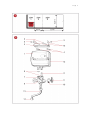
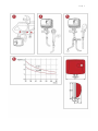
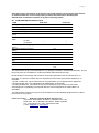
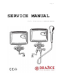
Page 1 SERVICE MANUAL Little flow heaters SERVICE MANUAL Page 2 Page 3 Page 4 Little flow heaters SERVICE MANUAL Electric non-pressure water flow heater of ●733 series is a product the shape design and dimensions of which determine it to be used both above and under the hand basin, sink, shower, etc. It is suitable for heating water in households, workshops, medical attendances and anywhere else with the need of instant hot water withdrawal. It can also be connected to domestic water station (Darling). Advantages of flow heaters easy operation, easy assembly and small dimensions fast and economic appliance heating control light instant and continuous hot water withdrawal economic and ecologic activator – reduces water and energy consumption swivel discharge arm with a pearlator tap or economic shower high reliability and safety of operation (increased lifetime of spirals) work with operating pressure from 0.08 MPa electronic protection of the appliance in emergency situations possibility of installation in bathrooms and lavatories in zone 1 – IP protection 25 (above the bathtub and shower inserts), pursuant to ČSN 33 2000-7-701 (Fig. 1) I. OPERATION INSTRUCTIONS A special low-pressure combination faucet has to be used with this product. Opening the hot water valve (red) on the combination faucet activates automatically heating of the flowing water. Turning the heating on is signalled with a red light on the front cover of the heater. Output temperature is controlled directly by the hot water valve on the combination faucet through water flow change. Its temperature drops as the flow grows. Closing the hot water valve on the combination faucet automatically deactivates heating, the signal light goes off and electricity consumption discontinues. II. SAFETY NOTICE The safety instructions contained in this chapter are based not only on the requirements of the EC standardised standards and guidelines, but take into consideration also the general safety of products, and result from practical experiences of users' behaviour. Consider any analogical or partially variant information that may occur in the next chapters of the present Manual secondary, and always follow the instructions stated in this particular chapter! - Prior to putting the appliance into operation please read carefully this Service Manual, view the figures and keep the Manual for further reference. - Check whether the information on the type plate corresponds with the voltage in your electric socket. - Never use the appliance with a damaged supply cord or plug, unless operates properly, if it fell on the ground and got damaged, or if it fell in water. In such cases take the appliance to an authorised service shop and get it checked, in order to ensure its safety and proper functioning. - The appliance is only designed to be used in households and for similar purposes! It is an appliance available to general public, designed to be placed in residential or commercial buildings. - In order to ensure supplementary protection, we recommend a current protector (RCD) to be installed in the electric circuit of the bathroom power supply, with rated operating current within 30 mA. Consult revision technician or electrician, as the case may be, - Separate electric circuit must be protected for type 0733 with 16 A circuit breaker at least, and for type 1733 with 25 A circuit breaker at least. - Electric and water supply installation must comply with valid electrotechnical regulations and standards. Page 5 - The heater must be installed in a non-freezing environment only, otherwise the product may get damaged. In case of freezing do not start the heater. - The heater must be permanently connected to fixed supply with an installed device enabling disconnection of all supply poles (except for the protective conductor), with the minimum 3 mm distance of contacts in open state! - Specific water resistance at 15°C must not drop below 1300 Ohm.cm (requirement of the ČSN EN 60335-2-35 standard). Drinkable water generally conforms to the above requirement. Get the information on water conductivity at the water supply administrator or at the hygienic station. - The minimum and maximum pressure of water in the supply piping must conform to the values stated in the technical data sheet of the heater. - The product's IP protection is 25; it can be installed in bathrooms, shower inserts and lavatories pursuant to ČSN 33 2000-7-701 in zones 1, 2 and 3 (Fig.1). - The flow heater is protected against spurting water (IP X5). - Do not cover the discharge outlets! Those outlets serve as ventilation to release water overpressure during heating. For that reason, minor water dripping occurs during heating. The dripping cannot be eliminated by tightening the faucet valve! By forced tightening of the valve you may damage the faucet! This phenomenon with these heater types is normal and therefore do not consider it a defect. - On the first putting the appliance into operation, unscrew the pearlator on the drain arm, or the shower adaptor, and open the blue combination faucet valve. With cold water flow the impurity residues left after the assembly and tightening of the valves will be cleared off the cold water supply piping. Close the blue valve. Open the red valve and let it open until the water from the flow heater starts flowing continuously (air removal). After fitting the pearlator or attaching the shower, the heater can be connected to power supply. - The flow heater is designed with an open outflow (non-pressure). For that reason, no stop valve or any other fitting or device shall be connected at the outflow. Use special low-pressure combination faucets only, and other accessories. These components are also supplied by the heater manufacturer. - Should you find out that there is lack of water in the water supply piping, close the hot water valve immediately to avoid flowing the water from the heater out back into the water conduit! - If there is air in the heater (e.g. in case of water supply discontinuation), bleed it similarly as when assembling the appliance (do not forget to disconnect the heater from the power supply). - The flow heater is designed for heating of cold running water only. It shall not be used for other heating, e.g. by connecting to electric tank, etc. - Check regularly the flow and remove the scale from the pearlator and shower (see IV Maintenance Instructions). - The heater must not be submerged under water (not even partially) or installed in an explosive environment. - Prevent children and irresponsible people from handling without supervision of a competent person! - Do not perform any interventions or repairs of the flow heater as long as it is connected to power network. - Let an authorised service shop workers deal with any repairs. - Avoid mechanical damage of the appliance and damage due to frost. - The supply pipe must not be damaged by sharp or hot objects or open flame, and must not be submerged in water. - Use only undamaged and correct power extension cords. - If the supply inlet of this appliance is damaged, it has to be replaced by the manufacturer, its service technician or a similarly qualified person in order to prevent a hazardous situation from occurrence. - Never use the appliance for a purpose different from that being defined and described in this Manual! Failing to follow the instructions advised by the manufacturer constitutes cessation of the right for warranty repair. - The manufacturer shall not be held liable for any damages caused by improper handling the appliance (e.g. fire, burning, scalding, etc.), and shall not be held liable for warranty of the appliance should the above safety instructions are not followed. Safety features of the product This flow heater ensures high operation reliability. The safety is guaranteed by three protection levels. On the first and every following connection of the heater to el. network the time safety Page 6 delay of closing the el. circuit is set (approx. 5 seconds). This safety feature protects the heater from overheating if thorough bleeding of the heater is not achieved by connecting it to the water supply piping. The flow heater is further equipped with the following safety features: 1) Pressure switch – shall not close el. circuit if water flow is insufficient. 2) Safety electronics - automatically discontinues water heating for a period necessary if the appliance overheats. Interrupted run of the heater indicates either failure in following the operation conditions advised by the manufacturer, or a failure of the heater. The cause of faulty function has to be removed immediately, since there is a risk of damaging the appliance. 3) Pressure fuse – protects from excessive inner water pressure. If this fuse is inactive, water starts flowing out on the rear side of the heater. If this situation occurs, immediately close both valves of the combination faucet and disconnect power supply. Make sure the sieve in the cold water supply to the heater, as well as the pearlator and shower element are cleaned regularly. If the above components get clogged, water flow reduces and the appliance will be put out of service until the causes are removed. All the safety features have to be repaired only by an authorised service shop worker! III. ASSEMBLY INSTRUCTIONS Note: With regard to 100% check by water pressure test, a little amount of water can be left in the heater which causes no harm. Cold water supply is indicated with a blue symbol, and hot water outflow is indicated with a red symbol. A Water connection – elevated installation (Fig.2) 1. Flow heater 2. Holder 3. Spiral dive 2 pcs 4. Wall plug, 2 pcs Ø 8 5. Screw fixing the upper cover of the heater to the holder - 2 pcs, Ø 3.9 x 16 6. Sieve 7. Alligator faucet nut, 2 pcs 8. Sealing, 2 pcs 9. Faucet 10. Rosette 11. Water inlet neck G 1/2" 12. Lower cover 13. Discharge arm with sealing 14. Spray head with sealing and pearlator 15. Security sheet, 2 pcs Close the main water inflow. Screw a low-pressure combination faucet with a decorative rosette on the water inlet neck G 1/2". Seal the threads on the water inlet. Insert sealing rings into the outlet terminals of the faucet. Loosen 2 screws fastening the cover on the sides of the flow heater so that the thrust bottoms in the holes on the rear side created a space for sliding in the attached holder. Mount on the holder. Mount the flow heater preliminary on the combination faucet and evenly tighten the alligator nuts using wrench No 16. Mark holes for wall plugs on the side. Disconnect the flow heater from the faucet. Bore the marked holes on the wall with a 8 mm drill bit into the depth of 40 mm. Place the wall plugs into the hole and fix the holder with two spiral dives. Insert a sieve into the flow heater cold water inlet marked with an arrow, unless this has already been done by the manufacturer. Put the heater on the fastened holder and tighten the 2 screws on the sides of the flow heater. Connect the combination faucet by even tightening of the alligator nuts. Before opening the main water closure, unscrew the pearlator on the drain arm or the shower saver. First open the cold water valve on the combination faucet to let contaminated water flow out. Open the hot water valve and bleed the flow heater. Mount the pearlator on the drain arm only when clean and bled water flows out. After that, the appliance can be connected to power supply. Page 7 B Water connection – low installation (Fig.23) Close the main water inflow. Fasten the combination faucet under the hand basin or the sink. Connect the cold water pipe (hose) of the combination faucet to the corner valve of cold water inlet. The corner valve outlet must have thread 3/8". Mount the flow heater on the wall in the same manner like for the elevated installation. The inlet and outlet of the heater must be directed upwards. When fixing the heater make sure the distance for connecting the inlet and outlet pipe (hose) of the combination faucet is sufficient. Connect the cold water inlet and outlet pipe (hose) of the combination faucet to the heater as indicated by colour arrows. Before tightening the alligator nuts insert a sieve in the cold water supply pipe – unless the manufacturer has already done so. Open the main water lock. Proceed in the same way as described for the elevated installation to bleed the heater and remove impurities from water. After that, the appliance can be connected to power supply. C Connection of water – flow heater with combination faucet and shower (Fig. 4) Connection – as described for elevated installation (A). D Connection of water – flow heater with combination faucet, swivel arm and shower (Fig. 5) Connection – as described for elevated installation (A). The appliance is connected to drinkable water supply, and is designed for preparation of hot service water. E Connecting the heater to electric network Heater – connect to fixed supply. The appliance must be connected with a protective conductor! Electric installation of heaters with fixed connection shall only be performed by an authorised firm holding a licence for works on electric equipments. Correctness of installation must be confirmed in the warranty certificate. Without that confirmation, the warranty for the product is not applicable! IV MAINTENANCE INSTRUCTIONS Maintenance of flow heater is very simple. It is only limited to maintaining its surface cleanliness, checking the cleanliness of the sieve in the cold water inlet, and cleaning of the pearlator or the shower element. Pearlator During cleaning, unscrew the pearlator from the swivel arm. Take the element out and clean the holes of it. Proceed in the opposite manner to assemble it. Shower element When cleaning the shower element, loosen the screw on the front drain surface. Take out individual elements and clean the flow channels on the periphery of the elements, e.g. using a soft brush. Proceed in the opposite manner to assemble it. If, despite the cleaning, the water flow of the heater is lower, you need to clean the screen in the water inlet to the heater. Cleaning the screen in the water inlet First disconnect the appliance using the protection element from the power supply and familiarise other heater users with its disconnection. Then close the water supply. Dismantle the heater from the wall and from the water inlet. Clean the screen (sieve) and proceed in the opposite manner to mount the heater back on. Protection from freezing and damage due to frost If the flow heater is mounted at a place with a risk of freezing in winter (e.g. cottages or cabins not occupied in winter), the appliance has to be dismantled and store it in such manner to avoid its exposure to frost. Pure removal of residual water in the heating element and labyrinth by blowing through the drain arm is not enough, and does not protect against damage caused by frost. Page 8 If the stated instructions are not followed and the appliance gets damaged by frost, the title to warranty repair ceases due to improper use of the product. Wipe the outer surfaces of the flow heater and the combination faucet with a soft clout damped in a detergent solution. Do not use aggressive solutions or rough cleaning agents! Let an expert deal with larger maintenance and repairs! V GRAPH OF WATER HEATING (Fig. 6) Temperature of heated water The graph shows dependence of maximum water flow A [l/min.] on the temperature outflowing water B [°C] for the 3,5 kW and 5 kW power inputs. The data apply even if the temperature of the inflowing water is 10°C. Example: From a 0733 (3.5 kW) type heater, water of 50°C temperature will outflow at the temperature of inflowing water 10 °C and flow of 1.2 l/min. VI ECOLOGY If the dimensions allow so, the symbols of materials used for production of packaging, components and accessories, as well as recycling symbols, are imprinted on all products. The symbols stated on products or in the accompanying documentation indicate that the electric or electronic products used shall in no case be disposed of together with municipal waste. To dispose of the product properly, hand it over at designated collection points where they will accept it free of charge. You will help to dispose of the product properly and maintain valuable natural resources, as well as prevent from potential negative impacts on environment and human health which might be the consequences of improper waste disposal. Seek further details from local authority or from the nearest collection yard. If this type of waste is disposed of improperly, fines may be imposed pursuant to national regulations. Should the appliance be put out of service definitely, the supply inlet should be cut off the power supply once disconnected; thus the appliance will be useless. WARRANTY TERMS The warranty term for the product is stated on the warranty certificate and counts from the date when the product was sold. The title for provision of free warranty repair of the product within the warranty period originates only when the electric installation of the product was performed an authorised company holding a valid licence for works on electrical equipments. Putting the appliance into operation has to be recorded by that company and confirmed on the warranty certificate (date, stamp and signature). ATTENTION The customer loses the title to free warranty repair if the product was not put into operation by the above specified person, and this fact was not recorded in the warranty certificate. Page 9 Parts that require intervention in the electric part of the appliance shall only be replaced with an authorised electric service shop! Failing to follow the instructions advised by the manufacturer constitutes cessation of the title to warranty repair! VII FLOW HEATER TECHNICAL DATA TYPE PTO 0733 Rated power input (kW) 3,5 Rated voltage (V) Rated current (A) Fuse protection (A) Rated section of conductors Cu 2 (mm ) RECOMMENDED - for hand basin - for sink - for shower Min water pressure in piping (MPa) Max water pressure in piping (MPa) Overpressure (MPa) Electric connection IP Protection level Approx. weight of the appliance (kg) Connection to cold water Dimensions L x W x H (mm) PTO 1733 5 230 15,2 16 □ 1,5 230 21,7 25 □ 2,5 • - - • • 0,08 0,6 0 Connect the flow heater to fixed conduit IP 25 1,6 G 1/2" 204x 8 0 x 175 The manufacturer shall not be held liable for any damages caused by unauthorised assembly. Should the product fail, do not hesitate to contact the nearest authorised service shop. EC Declaration of Conformity was issued for the product, pursuant to Act No 22/1997 Coll., as amended. The product complies with the requirements of the below government regulati ons, as amended: - NV No 17/2003 Coll., which defines technical requirements on low voltage electric appliances (corresponds with the Council Regulation No 2006/95/EC, as amended). - NV No 616/2006 Coll., which defines technical requirements on products in terms of their electromagnetic compatibility (corresponds with the Council Regulation No 2004/108/EC, as amended). The manufacturer reserves the right to minor deviations from the standard design that do not affect the function of the product. MANUFACTURER: Družstevní závody Dražice-strojírna s.r.o. (The Works Cooperative of Dražice – Machine Plant, Ltd.) Dražice 69, 294 71 Benátky nad Jizerou, Česká republika Tel.: +420 326 370 911, Fax: +420 326 370 980 e-mail: [email protected], www.dzd.cz Page 10 Complaints procedure Contact the manufacturer for any complaints within the warranty period. Send the product or hand it over in person, always with the Service Manual attached. Include the Warranty Certificate since it is the integral part of the Service Manual. No additionally sent manuals with warranty certificate or those handed over in person shall be regarded. Attach an accompanying letter to the product being sent – stating the reason for the complaint, and specify YOUR DETAIL ADDRESS. For warranty complaints contact the shop where the product was bought. Clean the product and pack it to avoid its damage during transport. For sanitary reasons we do not accept dirty product for repair. Records of warranty repairs: Product in warranty repair Order # from till Stamp and signature of repair shop Product in warranty repair Order # from till Stamp and signature of repair shop Product in warranty repair Order # from till Stamp and signature of repair shop Confirmation of connection of the heater by an authorised company Date, company stamp & signature Page 11 PRODUCT FICHE LOAD PROFILE ENERGY EFFICIENCY CLASS WATER HEATING ENERGY EFFICIENCY (%) kWh/ ANNUM THERMOSTAT TEMPERATURE SETTING (°C) ACOUSTIC PERFORMANCE (dB) FUNCTION ONLY IN THE LOW TARIFF ELECTRICITY WEEKLY ELECTRICITY CONSUMPTION Qelec,week,smart DAILY ELECTRICITY CONSUMPTION Qelec (kWh) MIXED WATER V40 (l) PTO 0733 PTO 1733 XXS A XXS A 39 39 478 475 - - 46 46 not not not not 2,198 2,181 - - 30-9-2015