1
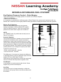
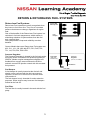
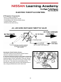
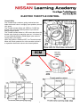
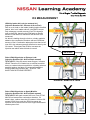
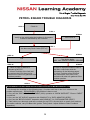
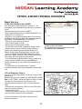
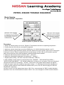
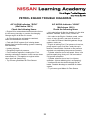
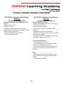
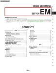
PETROL ENGINE
TROUBLE
DIAGNOSIS
May 2009
Foreword
The information in this Training Manual should not be interpreted as a basis for
warranty or goodwill claims against Nissan Motor Co. (Australia) Pty. Ltd. (NMA)
unless so designated.
This Technical Training Manual is intended for use by NMA & Nissan Dealership
Technical Personnel. It is not designed for the use by press or for customer
distribution.
Before quoting any specifications be sure to check the relevant Service Manual
and Technical Bulletins.
Right for alteration to data and specifications at any time is reserved. Any such
alterations will be advised by Nissan through Technical and Sales Bulletins.
©2009 Nissan Motor Company (Australia) Pty. Ltd.
Inc. Victoria
Ref: Technical Training Department.
Petrol Engine Trouble Diagnosis.
Nissan Australia. May 2009.
RETURN & RETURNLESS FUEL SYSTEMS
Fuel System Pressure Control – Petrol Engine
There are two types of fuel supply systems in common use on Petrol engines:
• Return Fuel Systems.
• Return-less Fuel Systems.
It is important to understand the 2 different types of Petrol Engine fuel systems as the pressures will vary
between the 2 and there will be slightly different testing procedures employed between these two systems.
Return Fuel Systems
Since the introduction of electronic fuel injection
systems until approx. 2000, all Nissan EFI engines
used Fuel Return Systems. These are slowly being
phased out as new model engines are introduced.
Injector Rail
With
Injectors
NOTE:
Y61 TB48DE is the only vehicle that currently uses a
Return Fuel System.
Intake
Manifold
Pressure
Fuel
Damper
Pressure Regulator
The Pressure Regulator is located on the end of the fuel
rail after the last injector and it varies fuel pressure
depending on engine load (manifold vacuum). A small
vacuum hose connected above the regulator diaphragm
keeps the pressure difference between the fuel rail and
the manifold constant. This enables consistent injection
quantity based only on changes in injector pulse width.
Typical fuel pressures are:
• At idle, vacuum hose On - 240 kPa
• Vacuum hose Off – 290 kPa.
This difference in fuel pressure is simply the difference
in manifold pressure (vacuum) between engine idle and
engine OFF (or at Wide Open Throttle).
Once the fuel rail is pressurised, excess fuel continually
returns to the tank via the pressure regulator valve.
Fuel Damper
A fuel damper is usually located at the fuel rail. Some
engines may use two fuel dampers.
Fuel Filter
The fuel filter may be located externally or within the
tank with the fuel pump. Refer to the Service Manual for
the location.
1
Fuel Filter
* Not all models
(Vacuum)
Pressure
Regulator
(Varies fuel
pressure
dependant on
manifold
vacuum)
Fuel Return
Fuel Pump
(Filter and Sender
Unit)
* Not all models
Fuel
Tank
Petrol Engine Trouble Diagnosis.
Nissan Australia. May 2009.
RETURN & RETURNLESS FUEL SYSTEMS
Measurement of the Fuel Pressure (Petrol Engines)
As part of an Engine no / poor running diagnosis, the Fuel Pressure is an important measurement to record
in order to narrow down the cause of a fault. Measuring Fuel Pressure will measure the pressure that the
fuel is under prior to entering the injector.
Obviously the Fuel won’t spray properly if the pressure is incorrect (too low). Also, the amount of fuel
entering the combustion chamber will be insufficient if the pressure is too low (Fuel starvation).
If the Fuel Pressure is too high, then the engine will have a rich running / excessive fuel consumption issue
Fuel system tests are:
• Pressure
• Residual Pressure Retention
Ensure there is sufficient fuel in the tank before conducting tests.
Fuel Pressure Release
On all systems, it is important to safely release residual fuel pressure before removing fuel hoses.
• Perform “FUEL PRESSURE RELEASE” with CONSULT in Work Support Mode. Ensure that engine stalls
and will not restart.
• Without CONSULT, remove the fuel pump fuse, run the engine until it stalls and ensure that it will not
restart.
WARNING: Great care must be taken to avoid fires when opening the fuel system.
Fuel Pressure Test on Return Systems
1. Install the Fuel Pressure gauge on the engine. Refer
to Section EC – “Basic Service” in the Service Manual
2. Switch Ignition ON. Ensure Fuel Pump activates &
then stops after a few seconds. Check for fuel leaks.
3. Start engine and read fuel pressure. Compare to
specifications in the Service Manual.
Check the following items if fuel pressure is too Low:
• Blocked filter or fuel pump pick up
• Restricted fuel lines
• Faulty pressure regulator.
Intake
Manifold
Pressure
Fuel
Damper
Pressure
Regulator
NOTE:
• If fuel pressure is LOW, carefully squeeze the return
line (resulting in blocking it) & watch a sharp & rapid
increase to approximately double the normal Fuel
Pressure spec. Only do this for a maximum of 3
seconds. If the pressure increase does occur the fuel
pressure regulator is faulty.
If not, either the level of fuel in the tank is low, the fuel
pump output is weak, a fuel line is blocked or the fuel
filter is blocked.
• If fuel pressure is too HIGH, either the pressure
regulator is faulty or the return line is restricted.
2
Fuel
Pressure
Gauge
Fuel Filter
* Not all models
Fuel
Return
Fuel Pump
(Filter and Sender Unit)
* Not all models
Fuel Tank
Petrol Engine Trouble Diagnosis.
Nissan Australia. May 2009.
RETURN & RETURNLESS FUEL SYSTEMS
Injector Rail
With Injectors
Return-less Fuel Systems
Return-less Fuel systems are easily recognised since
they have no fuel return line. They run at a constant
pressure that does not change, regardless of engine
load.
One of the benefits of the Return-less Fuel system is a
reduction in fuel tank temperature, which assists in
minimising emission of Hydrocarbons from the fuel
tank, cap and lines.
Less components & improved reliability are other
benefits.
Fuel
Damper
Current Models that use a Return-less Fuel system are:
K12, C11, J31, J32, N16 with ETC, R51, D40, T30,
T31, J10, Z33, Z34, Z50 & Z51.
Pressure Regulator
The Pressure Regulator is located in the fuel tank at the
fuel pump outlet. It maintains fuel pressure typically at
350 kPa. Modern engine management software and
feedback from oxygen sensors allows the ECM to
maintain correct fuel injection control with this constant
fuel pressure.
Fuel Pump
(Filter and
Sender Unit)
Pressure
Regulator
(Pre-set, non variable)
Fuel Return
Fuel Tank
Fuel Damper
A fuel damper is usually located at the fuel rail and
should not be confused with the old type pressure
regulator, as there is no return line or vacuum hose
connected to it.
The fuel damper is only intended for noise reduction
purposes. Some engines may have two fuel dampers
located at the fuel rail.
Fuel Filter
The fuel filter is usually located in the tank with the fuel
pump.
3
Petrol Engine Trouble Diagnosis.
Nissan Australia. May 2009.
RETURN & RETURNLESS FUEL SYSTEMS
Fuel Pressure Test on Return-less Systems
1. Install the Fuel Pressure gauge on the engine. Refer
to Section EC – “Basic Service” in the Service Manual
2. Switch Ignition ON. Ensure Fuel Pump activates &
then stops after a few seconds. Check for fuel leaks.
3. Start engine and read fuel pressure. Compare to
specifications in the Service Manual.
Injector Rail
With Injectors
Fuel
Damper
Check the following items if fuel pressure is too LOW:
• Blocked filter or fuel pump pick up
• Restricted fuel lines
• Faulty pressure regulator.
NOTE:
• DO NOT SQUEEZE OR CRIMP FUEL LINES!
• If fuel pressure is too HIGH, replace the pressure
regulator which is located in the fuel tank.
Fuel Tank
Fuel Pump
(Filter and
Sender Unit)
Pressure
Regulator
(Pre-set, non variable)
Fuel Return
Residual Pressure Retention (Both types of Fuel Systems)
Ensure that when the engine & fuel pump is switched OFF, fuel pressure is retained in the lines for the
specified period. Typically this should be no more than a 10% drop over 10 seconds.
If pressure is dropping away excessively, consideration needs to be given to the following items:
• Leakage in the reverse direction back to the tank.
• Leakage in the forward direction through leaking injectors (or fuel pressure regulator on Return Systems
only). If this is the case, the engine will be difficult to start & black smoke will be emitted from the exhaust.
Typical SST requirements for Fuel Pressure Testing
Adapter
KV 101118400
Adapter
KV 10117600 AUS
Gauge and Adapter
7211 and 7273
Fuel Line Removal
Tool
16441 6N210
4
Petrol Engine Trouble Diagnosis.
Nissan Australia. May 2009.
ELECTRIC THROTTLE CONTROL
Electric Throttle Control (ETC)
All new petrol engine vehicles are now fitted with
Electronic Throttle Control (ETC) systems (fly-by-wire).
There is no mechanical connection between the
accelerator pedal & the throttle valve on the engine.
ETC is a closed loop system that provides the ECM
with direct feedback from the Throttle Position Sensor.
The ECM will modify the actual throttle valve opening
compared to accelerator pedal movement based on
various program strategies, including the need to
minimise emissions.
The benefits of ETC are:
• Moving parts are reduced as well as the noise
transmission path of a cable.
• Integration of idle control, cruise control, traction
control and vehicle dynamic control systems.
Note: ETC systems have no external means to alter the
idle speed. It is controlled directly by the ECM. DO NOT
attempt to alter ANYTHING on the throttle body.
Mechanical Throttle Control (MTC)
The previous system was a very complex one, even
though it was mechanically controlled.
The actual throttle valve was connected via cable to the
Accelerator Pedal & directly operated by the driver.
However if there is a change in idle speed required
without input from the driver (e.g.: when A/C cuts in),
there needs to be a system in place to open an air
passage & increase air flow which in turn increases
engine speed.
Therefore with MTC, air bypass passages are made up
to control airflow under certain conditions etc.
Numerous combinations of Idle Speed control are
required to cope with numerous situations. Therefore
this saw the need for numerous passages & idle
solenoid devices to be added to the intake manifold /
throttle body in order to satisfy all these conditions.
5
Petrol Engine Trouble Diagnosis.
Nissan Australia. May 2009.
ELECTRIC THROTTLE CONTROL
ETC System Components
The ETC system consists of:
• Accelerator Pedal Position Sensor
• Throttle Body with Throttle Actuator Motor
• Throttle Position Sensor
• ECM and associated wiring.
Accelerator Pedal Position Sensor
The ECM monitors the Accelerator Pedal Position
Sensor to determine the driver’s input.
It uses this signal along with its other inputs to determine
the amount of throttle opening requested. It contains two
potentiometers and the combination of the two signals
allows the ECM to calculate an average voltage output
from the two. This allows the pedal position to be
determined with greater accuracy and reliability than if
only a single potentiometer sensor was used.
6
Petrol Engine Trouble Diagnosis.
Nissan Australia. May 2009.
ELECTRIC THROTTLE CONTROL
Throttle Body
The Throttle body contains a spring mechanism that
holds the throttle valve in a slightly open position (around
10% open).
The Throttle Actuator Motor will OPEN or CLOSE the
throttle valve from this default position to provide the
desired engine speed.
The Throttle Actuator Motor is a DC motor that drives the
throttle valve through a reduction gear set. It is driven by
a Pulse Width Modulation (PWM) signal (also called a
varying duty cycle signal).
When the ignition is switched OFF, the Throttle Actuator
Motor will remain powered for a few seconds to allow it
to reposition the throttle valve to the closed position.
ECM
TPS sends
movement
signal back
to ECM
Driver
command
signal sent
to ECM
ECM Drives
12V DC
MOTOR
7
Motor turns
gears &
throttle
valve
Petrol Engine Trouble Diagnosis.
Nissan Australia. May 2009.
ELECTRIC THROTTLE CONTROL
Duty Control
Numerous electrical devices are controlled via Duty
Control. This can also be referred to as Pulse Width
Modulation.
This is a simple means of variable current control of a
device to any desired speed or position (dependant on
the device being controlled such as solenoids or
motors).
Example; Control of a Simple 12V DC Fan Motor
1. The 1st diagram to the above right shows the Fan
Motor controlled (switched) internally via an ECM. It is
currently OFF. Therefore it’s rotation speed is 0rpm.
2. The 2nd diagram shows the Fan motor switched to
ON. It’s rotation speed is 3000rpm. There are NO
resistors in the wiring or switches. It is being fed the full
amount of battery power.
3. Here the ECM switches the small switch ON & OFF
repeatedly. The switch is ON for 1 second. The switch
then goes OFF for another second. Then it goes back
to ON for 1 second.
Half the time OFF vs Half the time ON means the fan
motor only works at approximately half speed.
(1500rpm).
If the switch was ON for 2 seconds & OFF for 1 second,
the fan would rotate at approximately 2000rpm.
Obviously the ON & OFF switching will cause a notable
speed up & slow down of the motor every 1 second. It’s
operation won’t be very smooth.
Therefore the ECM switches ON to OFF in smaller
increments of time such as Milliseconds to smooth out
the operation of the device.
4. The last diagram shows the traditional means of
current control via a simple hand operated switch.
There are only 3 speed possibilities available; 0rpm.
1500rpm & 3000rpm.
Lo speed (1500rpm) is achieved via the current being
fed to the motor through a resistor. The Hi speed circuit
has no resistor.
8
Petrol Engine Trouble Diagnosis.
Nissan Australia. May 2009.
ELECTRIC THROTTLE CONTROL
ETC Failure Modes
Throttle Actuator Motor
Should there be a failure of the Throttle Actuator Motor; the ECM will be unable to control the throttle valve.
In this case, the internal spring mechanism will provide around 10% throttle opening which will allow the
engine to run up to approx. 1,100 ~ 2,000 RPM and be driven to a place of repair.
The ECM will still have small amount of control over engine speed. If the Accelerator Pedal Position Sensor
is working normally, the ECM will vary the ignition timing (retarding) or injector operation to pull the engine
speed lower for idle. When the accelerator pedal is depressed, it will then advance the ignition timing to
obtain the full effect of the default 10% open throttle.
Accelerator Pedal Position Sensor (APPS)
If the ECM cannot receive reliable information from the Accelerator Pedal Position Sensor it will disable the
Throttle Actuator Motor so it returns to the default 10% position.
Throttle Position Sensor (TPS)
If the ECM cannot receive reliable information from the Throttle Position Sensor it will disable the Throttle
Actuator Motor so it returns to the default 10% position.
Relearning Functions
The ECM constructs various self learning functions that are critical to Electronic Throttle Control operation.
If the ECM, APPS or TPS connectors are removed OR there are idle concerns, the following procedures
MUST be carried out:
• Accelerator Pedal Released Position Learning (using ignition key switching)
• Throttle Valve Closed Position Learning (using ignition key switching)
• Idle Air Volume Learning (using CONSULT).
Refer to “Basic Service” in Section EC of the Service Manual for more detail.
NOTE: ETC systems are affected by carbon build up at the throttle valve and bore and may require periodic
cleaning to restore correct idle performance.
Relearning functions MUST also be conducted whenever the throttle is cleaned.
9
Petrol Engine Trouble Diagnosis.
Nissan Australia. May 2009.
O2 MEASUREMENT
Measurement of Oxygen Content after Combustion
All modern petrol engines have Oxygen Sensors installed in the exhaust manifold. These sensors generate
a voltage signal & sends this voltage back to the ECM.
A varying amount of Oxygen seen by the sensor will create a varying voltage signal. The ECM sees this
varying voltage & then it MAKES AN ASSUMPTION ON HOW MUCH FUEL ENTERED THE
COMBUSTION CHAMBER.
If the Oxygen Sensor (O2S) measures a HIGH level of Oxygen;
This will tell the ECM the A/F Ratio was LEAN. Therefore on the engines next cycle the ECM will add
MORE Fuel.
If the Oxygen Sensor (O2S) measures a LOW level of Oxygen;
This will tell the ECM the A/F Ratio was RICH. Therefore on the engines next cycle the ECM will add
LESS Fuel.
Small Amount of Fuel (LEAN)
This condition will create a situation where the A/F mix will have a short burn time. There is not enough fuel
to make a long burn time. Since the small quantity of fuel has quickly burnt up, the burning will stop & there
will be a certain amount of Oxygen remaining amongst the exhaust gases.
These gases are expelled out the exhaust valve, the O2 Sensor samples these spent gases & there it will
see this remaining O2 content. This will create a voltage signal which indicates to the ECM that the amount
of fuel that was sprayed out of the injector was a small amount, therefore next cycle it will increase the
injection rate.
Large Amount of Fuel (RICH)
This condition will create a situation where the A/F mix will have a long burn time. There is now more fuel to
make a longer burn time. Since the larger quantity of fuel makes a longer burn time, nearly the entire O2
content will burn.
The spent gases left over in the combustion chamber will contain very little if any O2 content. These gases
are expelled out the exhaust valve, the O2 Sensor samples these spent gases & there it will see that there
is hardly any remaining O2 content. This will create a voltage signal which indicates to the ECM that the
amount of fuel that was sprayed out of the injector was a large amount, therefore next cycle it will decrease
the injection rate.
10
Petrol Engine Trouble Diagnosis.
Nissan Australia. May 2009.
O2 MEASUREMENT
Ideal Air Fuel Mix (14.7:1)
The right amount of Air to Fuel will result in an ideal
burn.
IDEAL 14.7:1
LEAN by Short Injection Duration
(Excess of Air to Fuel)
The injector is opened for a short period of time by the
ECM. Only a small amount of fuel enters the
combustion chamber. This results in a short burn time,
therefore some O2 content will be left over after the
burning has stopped. This left over content of O2 is
expelled & then seen by the O2 sensor. This signals to
the ECM that the mix was lean, therefore will result in
an increased rate of injection (more fuel) for the next
cycle.
SMALL INJECTION QUANTITY
LEAN by Fuel Starvation (Injection Duration OK)
(Excess of Air to Fuel)
Due to low fuel pressure / blocked filter / blocked
injectors etc, this results in a short burn time due to the
lack of fuel. This again results in some O2 content
being left over. This left over content of O2 is expelled &
then seen by the O2 sensor. This signals to the ECM
that the mix was lean, therefore will result in an
abnormal increase in the rate of injection for the next
cycle in order to compensate for the “lack of fuel”
condition.
11
FUEL STARVATION PROBLEM
Petrol Engine Trouble Diagnosis.
Nissan Australia. May 2009.
O2 MEASUREMENT
LEAN by Intake Air Leak (un-metered air)
(Injection Duration OK - Excess of Air to Fuel)
Due to an air leak on the intake (leaking intake manifold
gasket, hole in air intake tube etc.) the MAFS sensor
only measures a certain amount of air This signal is
sent to the ECM, therefore the ECM adds a specific
amount of fuel which is relevant to the amount of air
measured.
Air which is leaking through a hole or a leaky gasket is
added to the combustion chamber with an insufficient
amount of fuel. Combustion takes place but there is left
over O2 in the exhaust gases & therefore is seen by the
O2 sensor. This signals the ECM to increase the
injection rate above what it thinks is normal.
INTAKE AIR LEAK
AIR LEAKS!!
False LEAN Signal due to Exhaust Leak
(Injection Duration OK. Air/Fuel Ratio normal)
REMEMBER! If the O2 sensor sees Oxygen, it means
LEAN! Therefore if O2 leaks into an exhaust manifold
due to a cracked exhaust manifold or a leaking exhaust
manifold gasket, the false O2 content will make the
ECM increase the injection rate – EVEN IF THE
INJECTION RATE WAS PERFECT!
EXHAUST MANIFOLD LEAK
False LEAN Signal due to Spark Missfire
(Injection Duration OK. Air/Fuel Ratio normal)
REMEMBER! NO spark means NO burn. Even if TOO
MUCH fuel entered the combustion chamber, if it
doesn’t burn, neither does the O2 content. Unburnt O2
means LEAN! As a result the ECM increases the
injection rate to add more fuel to an engine that doesn’t
need anymore fuel.
12
X
NO SPARK
Petrol Engine Trouble Diagnosis.
Nissan Australia. May 2009.
O2 MEASUREMENT
RICH
(Normal Air Quantity with Excess Fuel)
If there is an excess amount of fuel added (leaking
injectors or excessive injection duration etc.), not all of
the fuel will burn because in this case the burning will
stop due to all the oxygen being burnt up. RAW FUEL
WITHOUT OXYGEN WILL NOT BURN ON IT’S OWN.
The excess fuel will be expelled out of the exhaust
valve, however the reason why the O2 sensor will
indicate RICH is because it cannot sense any O2 in the
expelled exhaust gases. NOT because of the raw fuel
left over.
AN OXYGEN SENSOR CAN ONLY SEE OXYGEN.
It cannot see raw fuel.
RUNNING RICH / FLOODING
Using Air Fuel Alpha in CONSULT II to indicate measured Oxygen Content
Display A/F ALPHA in DATA MONITOR or DATA MONITOR (SPEC) CONSULT. If the A/F Alpha shows a
reading close to 100%, (typically 95% ~ 105%) then the engine is running close to or at it’s originally
programmed map.
I.e.; The ECM see no problems with the content of left over O2 it’s measuring in the exhaust gases. The
balance of Fuel Quantity to Air Quantity in the engine is normal.
Conventional O2 Sensor
T30 / K12 / C11 / J10
Constantly switches from 0.1V to
0.9V. Average of 0.5V
Wide Band Type 1
R51 / D40 / Z50 / Z33 (6 wire)
Ideal = 1.5V
RICH = towards 1V
LEAN = towards 4V
13
Wide Band Type 2
T31 / Z51 / J32 / Z33 / Z34 (4 wire)
Ideal = 2.2V
RICH = towards 0.5V
LEAN = towards 5V
Petrol Engine Trouble Diagnosis.
Nissan Australia. May 2009.
PETROL ENGINE TROUBLE DIAGNOSIS
Check In
STEP 1
STEP 2
STEP 2a
Verify on the vehicle what the incident is & compare
to what is described by the Customer
Can’t Fault it?
STEP 3
Are there any Fault Codes (DTC’s)?
STEP 4a
STEP 5a
No
The fault is basic.
FUEL. AIR. SPARK. POWER. GROUND
Yes
STEP 5b
STEP 4b
1. Refer to page in SM that is
relevant to the DTC.
2. Inform TechLine of the fault and
the actions that YOU have so far
carried out & other info gathered if the
problem persists.
1. Refer to Symptoms Matrix Chart in
the SM in conjunction with the
information on the following pages.
2. Inform TechLine of the fault and
the actions that YOU have so far
carried out & other info gathered if the
problem persists.
STEP 6
PRIOR TO COMPLETION OF REPAIR AND HANDING BACK TO THE CUSTOMER
1. Go through the checklist on the following page. Consider each item in the list in relation to the
problem experienced – REGARDLESS if the problem is there or not!
2. Carry out the “IDLE AIR VOLUME LEARN” (IAVL) operation in “WORK SUPPORT”. Ensure “CMPLT”
is achieved.
3. Carry out the “A/F ALPHA” inspection with CONSULT II in “DATA MONITOR (SPEC)”
4. Carry out the “B/FUEL SCHDL” inspection with CONSULT II in “DATA MONITOR (SPEC)”
5. Take vehicle on a thorough road test, re-check for any DTC’s & re-do IAVL on return from road test.
(For earlier vehicles, carry out Base Idle, Ignition Timing check / adjust & Mixture Ratio Feedback
inspection)
14
Petrol Engine Trouble Diagnosis.
Nissan Australia. May 2009.
PETROL ENGINE TROUBLE DIAGNOSIS
1. POWER AND GROUND (more detail further on)
(a) Battery – Is it charged? Can it hold a charge? Is it being charged? Does it pass a load test?
(b) Alternator. Can it cope with high electrical loads? Switch on all accessories & check it’s output under
load.
(b) Condition of battery terminals? Fusible links are in good condition – terminals clean & tight?
(c) Main ground connections are in good condition?
(d) Fuses – they are in the correct place & OK? There are typically 3 x different locations where fuses are
located. CHECK ALL LOCATIONS!
HAS THE VEHICLE GOT DECENT POWER SUPPLY & GROUND CONNECTIONS?
2. FUEL
(a) Is there Fuel in the tank? Who was the last to put Fuel in the tank? What kind of Fuel went into the tank?
Run engine on known good fresh fuel if in doubt.
(b) Fuel Pressure (1) – Measure it with a known good FP gauge & write the figures on the R/O. Measure the
FP at idle & again under FULL LOAD. Ensure the tank pick-up, pump, filter, return system (if applicable) is
OK. Refer to section EC – Basic Service in the Service Manual.
(c) Fuel Pressure (2) – Can the system maintain a residual pressure with the Engine OFF? If the pressure
drops away over 20min, where is it going? Back to the tank? Through leaking injectors or fuel pressure
regulator diaphragm? Leaking injectors or F-P regulator will contribute to hard start & black smoke emission.
3. IGNITION SYSTEM
(a) The CORRECT type of spark plugs for the engine are fitted?
(b) Spark plugs are worn / due for replacement?
(c) Ignition leads, distributor cap is in good condition?
(d) Ignition coil unit, coil power supply, is coil ground connection OK? (A poor coil ground can cause
premature coil failures)
4. COMPRESSION (Air)
(a) Measure with a known good compression gauge & write the figures on the R/O. Do both a DRY & then
followed by a WET compression check. Refer to section EM of the Service Manual for procedure.
(b) Air intake system – Are their any air leaks? oil cap, dip-stick, throttle body gasket & bypass hoses,
vacuum hoses fitted correctly?
(c) Air intake system – Blockage or air flow interference?
(d) Air outlet system (Exhaust) – Blockage? Leaking manifold gaskets or cracked exhaust manifold?
(e) EGR & crankcase ventilations systems operating OK?
5. ENGINE MECHANICAL TIMING INDICATION SYSTEM
(a) CKPS & CMPS signal plates functioning OK / Serviceable? Sensors mounted correctly? Flywheel has
been fitted in the correct place?
(b) Camshaft / Crankshaft timed correctly? Variable camshaft timing mechanism & timing chain condition
OK?
6. ENGINE OIL, COOLANT & PREVIOUS WORK HISTORY
HAS THE VEHICLE GOT A DECENT SERVICE HISTORY?
(a) Oil level is correct? Is it over/under full? Due for changing?
(b) Is it the correct grade / viscosity for the engine?
(c) Coolant level & condition is OK? Genuine coolant used? Cooling system is functioning OK?
(d) Have you got records of other PREVIOUS WORK HISTORY (Nissan dealer or Non Nissan Dealer),
FITMENT OF NON GENUINE PARTS & AFTER MARKET ACCESSORIES?
15
Petrol Engine Trouble Diagnosis.
Nissan Australia. May 2009.
PETROL ENGINE TROUBLE DIAGNOSIS
Checklist Continued
7. NATS
All keys start the car OK? Remove keys from key ring set & retry. Ensure there are no other electronic
devices that interfere with NATS keys operation when starting.
8. ILLOGICAL INPUTS INTO THE ECM.
(a) Whilst being driven as well as stationary, ensure that inputs such as “P/N Posi Sw” & “Brake Sw” are
input correctly. For a complete reference list, refer to section B – EC (“TROUBLE DIAGNOSIS – CONSULT
Reference Value in Data Monitor Mode”) of the Service Manual.
(b) If possible, drive the vehicle fitted with a “KNOWN GOOD” Mass Air Flow Sensor.
9. PRE-PROGRAMMED ECM FAILSAFE OPERATIONS.
(a) Ensure the customer does NOT drive with the brake pedal applied. (Specifically on T31 & Z34)
(b) Ensure that the brake pedal & brake pedal switches (Stop Lamp & ASCD cut) are correctly adjusted.
Ensure the clutch pedal ASCD cut switch is correctly adjusted (where fitted)
(c) Ensure the brake lights globes & associated circuit is functioning correctly. Inspect for open circuit brake
light globes &/or wiring, connections & grounds are OK. (Specifically on N16 Hatch with ETC).
16
Petrol Engine Trouble Diagnosis.
Nissan Australia. May 2009.
PETROL ENGINE TROUBLE DIAGNOSIS
Basic Service
1. Idle Speed Check
With CONSULT, select “ENGINE & then “DATA
MONITOR” & view the idle speed by viewing “Engine
Speed” in “Main Signals”)
2. Ignition Timing Inspection
Given that the engine is installed with a CKPS
monitoring the movement & position of the Crankshaft
(flywheel) & a CMPS monitoring the movement &
position of the inlet camshaft, the ECM has the ability to
“see” where the Crankshaft is in relation to the
Camshaft & adjust the timing by itself accordingly.
Therefore it is NOT necessary to check the ignition
timing at normal service intervals etc.
HOWEVER, it maybe necessary to inspect the ignition
timing as part of a Trouble Diagnosis procedure.
If so desired, the actual Ignition Timing can be
inspected in the traditional manner to ensure the CKPS
& CMPS systems are operating correctly.
As shown right, remove No. 1 ignition coil, install
Special Service Tool (SST) # E7032 & check the
ignition timing. The engine must be idling at operating
temperature & ALL accessories OFF. Compare the
reading seen by the timing light with the “Ignition
Timing” reading in Data Monitor on CONSULT.
Typical Scenario’s which may cause the Ignition timing
to be out of specification;
• The Driveplate / Flywheel has been removed & reinstalled in the wrong place. (1 bolt hole out etc.)
• The inlet camshaft variable timing mechanism has
jammed in the advanced or retarded position. Typically
due the engine oil never being changed.
• Foreign object has damaged the sensor pick-up ring
on the Driveplate / Flywheel. Remove the starter motor
or inspection plate to check inside the bell-housing.
• Foreign object / material has damaged / obstructed
the camshaft signal plate / sensor.
• Idle Air Volume Learn (IAVL) hasn’t “Completed”
(CMPLT)
• “Target Ignition Timing Adj.” located in “WORK
SUPPORT” in CONSULT is incorrectly set.
NOTE: Y61 TB48 engines require inspection /
adjustment of the ignition timing every 20,000km’s.
17
Only use the Timing Light adapter SST. NEVER
use the loop wire in the harness.
Petrol Engine Trouble Diagnosis.
Nissan Australia. May 2009.
PETROL ENGINE TROUBLE DIAGNOSIS
Basic Service
3. Accel’r Pedal Released Pos’n Learning & Throttle Valve Closed Pos’n Learning.
THIS SIMPLE OPERATION IS CRITICAL!
Ensure the time frame suggested above for each key position is
observed. “10 sec” means 10 actual seconds on an accurate watch or
stop watch. NOT 10 “mini” seconds or 10 “that’ll be right” seconds!!
This 2 in 1 learning operation is an EXTREMELY important operation that MUST be carried out for any of
the following reasons;
• After the Reprogramming of an ECM – BUT BEFORE THE ENGINE IS STARTED!!
• A new or substitute ECM is installed in the vehicle. (Along with reprogramming ALL of the NATS ignition
keys. Make sure you get ALL THE KEYS from the owner / driver)
• A new or substitute Throttle Body Unit is installed on the vehicle.
• The existing throttle body unit is cleaned.
• Battery power has been lost for a long period of time.
• Prior to carrying the Idle Air Volume Learn (IAVL) operation.
18
Petrol Engine Trouble Diagnosis.
Nissan Australia. May 2009.
PETROL ENGINE TROUBLE DIAGNOSIS
Basic Service
4. Idle Air Volume Learn (IAVL)
The completion of this operation in around 15 ~ 20
seconds is a good indication that the engine operation
is OK.
Reasons why the IAVL will not “CMPLT”.
• Both Target settings found in “WORK SUPPORT” on
CONSULT are not set to “0”
• Engine is not at operating temperature. Even though
the Engine may feel hot, make sure this temperature is
indicated in “DATA MONITOR” on CONSULT.
• Engine is too hot (above 90 deg C)
• Poor Power Supply to ECM
• Bad Ground Connections for ECM
• An Electrical Load is ON. (Heater fan, lights, audio)
• Switch inputs such as P/N Posi, Power Steering
pressure are indicating that the transmission is in
Neutral or the Power Steering system is under load.
• There is a BASIC ENGINE MECHANICAL problem
such as an intake system air leak, compression issues,
fuel supply issues or ignition system issues.
• The Accelerator Pedal Released Position Learning &
Closed Throttle Position Learning has NOT been
carried out properly. It may need to be repeated up to
20 times.
• Throttle valve isn’t closed properly. Typically
excessive carbon is fouling the operation of the throttle
unit.
5. Fuel Pressure Check
This is for engines that have a “Returnless” type of fuel
system only.
Ensure that there is a CONSTANT PRESSURE OF 350
kPa AT ALL TIMES - whilst the engine is idling, & under
full load. The Fuel pressure should never vary.
Check the following items if the Fuel Pressure is too
LOW;
• Blocked fuel pump pick-up / filter (the fuel filter forms
part of the pump assembly)
• Restricted fuel lines
• Faulty fuel pressure regulator. (The pressure regulator
also forms part of the fuel pump assembly)
If the Fuel Pressure is too HIGH, replace the fuel
pressure regulator.
19
For T31 QR25, carry out the “Closed Throttle
Position Learn” procedure.
For all other ETC engines, carry out the “Idle
Air Volume Learn” procedure.
Petrol Engine Trouble Diagnosis.
Nissan Australia. May 2009.
PETROL ENGINE TROUBLE DIAGNOSIS
Basic Service
6. Clearing the “Self Learn”
Select “SELF LEARN CONTROL” from the work
Support menu & then touch “CLEAR”
This operation clears the LONG TERM A/F Alpha
values stored in the ECM. This should be carried out
after a major engine service or after the repair of an
engine running fault.
NOTE;
• ALPHA reading below 100% (e.g; 75%) indicates that
the engine is running TOO RICH
• ALPHA reading above 100% (e.g; 125%) indicates
that the engine is running TOO LEAN or has a missfire
condition (not burning O2).
20
Petrol Engine Trouble Diagnosis.
Nissan Australia. May 2009.
PETROL ENGINE TROUBLE DIAGNOSIS
Basic Service
6. “A/F ALPHA” Inspection
6 cylinder engine displayed. 2 separate
banks of cylinders. 4 cylinder has 1 bank.
Procedure:
1. Road Test vehicle briskly for 10 km’s. Engine & Transmission should be at operating temperature.
2. Confirm that the IAVL can be successfully completed.
3. Ideally the vehicle should have more than 5000km’s on it. (Vehicle has been properly “run in”).
4. Ensure that the engine has been properly serviced. Ensure the correct grade / type of oil is in the engine
& the level is correct. Ensure components such as spark plugs, air filter’s etc are serviceable / genuine
parts. Ensure that the correct Part Numbered components have been installed.
5. Ideally the barometric pressure should be 98.3 – 104.3 kPa.
6. Ideally the atmospheric temperature is between 20 – 30 deg C.
7. Engine speed is idling, (The IAVL must have achieved a “CMPLT”).
8. With CONSULT select options in the following order; “ENGINE” – “DATA MONITOR (SPEC)” –
“SELECTION FROM MENU” – “A/F ALPHA” (select the 2 of them for a 6 cyl engine. There are 2 banks of
cylinders that need to be monitored) – “START”. The screen in the graphic above should now appear.
9. With the engine under the conditions requested in steps 1 ~ 6, what does the black bar indicator do?
(i) Does it remain stable & central within the hashed area? (If so, all is OK. See next page for “B/FUEL
SCHEDULE” inspection.)
(ii) Does it move out of the hashed area below 100%? If so, see next page for “RICH” trouble indication.
(iii) Does it move out of the hashed area above 100%? If so, see next page for “LEAN” trouble indication.
21
Petrol Engine Trouble Diagnosis.
Nissan Australia. May 2009.
PETROL ENGINE TROUBLE DIAGNOSIS
A/F ALPHA Indicates “RICH”
(Well below 100%)
Check the following Items:
A/F ALPHA Indicates “LEAN”
(Well above 100%)
Check the following Items:
• Engine Oil is contaminated with excessive fuel or
it is the wrong viscosity or overdue for changing.
Change engine oil & filter if in doubt.
• Air Flow through the air intake is restricted,
check for interference of airflow.
• Fault with EVAP system (fuel is being drawn
directly from fuel tank breathing system & entering
inlet manifold.)
• Leaking injectors.
• Excessively high fuel pressure.
• Fuel Pressure regulator is leaking fuel. Fuel
entering combustion chamber via the vacuum hose
connected to it. (This applies to engines with a
return type fuel system only)
• Try a known good Mass Air Flow Sensor.
• Air Leaks before & after the throttle or in the Inlet
Manifold. Gaskets, seals, hoses, cracks etc.
• Air Leaks in the Engine. Gaskets, seals, rocker
cover, oil cap, dip stick, rear main oil seal etc.
• Air Leaks in Exhaust. Manifold gaskets, flange
gaskets, cracks etc.
• Engine is lacking Fuel. Fuel pressure is too low,
pump output is poor, fuel filter / tank pick-up is
blocked, hoses kinked / blocked or the pressure
regulator not maintaining the pressure correctly.
• Cylinder miss-fire due to bad spark. Worn / non
genuine spark plug, faulty coil / coil connection /
coil ground connection.
• Cylinder miss-fire due to bad / no injector
operation. (injector dribbling fuel, not spraying).
• Interference with the airflow through the air
intake. Possible blockage or modified air intake
system.
• Try a known good Mass Air Flow Sensor
22
Petrol Engine Trouble Diagnosis.
Nissan Australia. May 2009.
PETROL ENGINE TROUBLE DIAGNOSIS
7. “B/FUEL SCHDL” Inspection (Base Fuel Schedule)
Procedure:
1. Road Test vehicle briskly for 10 km’s. Engine & Transmission should be at operating temperature.
2. Confirm that the IAVL can be successfully completed.
3. Ideally the vehicle should have more than 5000km’s on it. (Vehicle has been properly “run in”).
4. Ensure that the engine has been properly serviced. Ensure the correct grade / type of oil is in the engine
& the level is correct. Ensure components such as spark plugs, air filter’s etc are serviceable / genuine
parts. Ensure that the correct Part Numbered components have been installed.
5. Ideally the barometric pressure should be 98.3 – 104.3 kPa.
6. Ideally the atmospheric temperature is between 20 – 30 deg C.
7. Engine speed is idling, (The IAVL must have achieved a “CMPLT”).
8. With CONSULT select options in the following order; “ENGINE” – “DATA MONITOR (SPEC)” –
“SELECTION FROM MENU” – “B/FUEL SCHDL” – “START”. The screen in the graphic above should now
appear.
9. With the engine under the conditions requested in steps 1 ~ 6, what does the black bar indicator do?
(i) Does it remain stable and central within the hashed area? If so this is OK. See earlier page for “A/F
ALPHA” inspection & check. If A/F ALPHA as well as B/FUEL SCHDL is OK, engine condition is normal.
(ii) Does it move out of the hashed area below the indicated value? If so, see next page for “Fuel Delivery
Increase” inspection.
(iii) Does it move out of the hashed area above the indicated value? If so, see next page for “Fuel Delivery
Decrease” inspection.
23
Petrol Engine Trouble Diagnosis.
Nissan Australia. May 2009.
PETROL ENGINE TROUBLE DIAGNOSIS
B/F SCHDL Indicates a Fuel Delivery
Decrease
Check the following Items:
B/F SCHDL Indicates a Fuel Delivery
Increase
Check the following Items:
Interference with Air Flow through the intake
system:
• Restriction of Air-Flow.
• Blocked Air Filter.
• Modified Air Intake System. Non standard
components in Air Intake system have been fitted.
• Valve clearances incorrect.
• Engine Compression is not to spec.
• Try a known good MAFS.
Excessive Engine Friction:
• High viscosity Engine Oil. Use correct grade of
engine oil for the engine.
• Engine Oil Level too high.
• Engine Oil is overdue for changing. (High
viscosity).
• Excessive external drive belt tension.
• Mechanical fault with engine. (High engine load
required to turn engine)
• Mechanical fault in Transmission. (High engine
load required to drive transmission)
Insufficient Combustion:
• Valve clearances incorrect.
• Valve Timing incorrect. (Correlation between
camshaft & crankshaft is incorrect).
• Intake Valve Timing Control mechanism fault.
(Valve timing advance / retard unit could be
jammed).
Other:
• Interference with the airflow through the air
intake. Possible blockage or modified air intake
system.
• Try a known good MAFS.
24
Petrol Engine Trouble Diagnosis.
Nissan Australia. May 2009.
ADR 81/01 FUEL CONSUMPTION TEST PROCEDURE
THIS LABEL IS FITTED SO THAT THE CUSTOMER CAN COMPARE THE FUEL
CONSUMPTION OF DIFFERENT VEHICLE MODELS.
IT DOES NOT SUGGEST THE ACTUAL FUEL CONSUMPTION OF THE VEHICLE.
ACTUAL FUEL CONSUMPTION OF THE ENGINE UNDER EVERYDAY DRIVING
CONDITIONS IS TYPICALLY 15% ~ 34% HIGHER THAN THE FIGURE QUOTED ON
THE LABEL.
The ADR 81/01 Test Cycle (sourced directly from www.greenhouse.gov.au/fuelguide)
The test cycle simulates an 11 km trip with an average speed of 33.6 km/h. Approximately two thirds of the
test time simulates urban-stop-go driving where the average speed is 18.8 km/h with the final third of the
test drive time being similar to driving on a highway with the vehicle driven to over 100 km/h.
The vehicle used in the test exactly matches the vehicle as it appears in the new vehicle brochure.
(I.E; NO ACCESSORIES ARE FITTED)
25
Petrol Engine Trouble Diagnosis.
Nissan Australia. May 2009.
EFFECTS ON PETROL ENGINE FUEL ECONOMY
Increased purchasing cost of Fuel.
Rising fuel costs are giving the customer the belief that the vehicle is at fault. Especially if the customer
adds fuel to the vehicle in set amounts of dollars every week etc.
Towing. Roof Racks / Bars.
Even though many Nissan vehicles have remarkable towing capacities – the fuel consumption will be
greatly affected as a result of towing. Especially if the vehicle is towing something on or close to the
maximum towing capacity.
If roof racks or bars are fitted (with or without contents) this will greatly effect fuel consumption.
Wrong Engine Oil / Poor Service History
Modern engines are extremely sensitive to Engine Oil viscosity. Ensure that only Nissan 7.5W 30 engine is
used. Irregular servicing will easily cause poor fuel consumption concerns as well.
Incorrect Wheels / Tyres. Vehicle is Overweight &/or Modified. Aftermarket accessories
Ensure that the original spec wheels & tyres are fitted to the vehicle in question. Increased rolling resistance
will cause poor fuel consumption. Additional parts on the exterior of a vehicle such as roof racks and
spoilers, or having the window open increases fuel consumption, in some cases by over 20%.
Tyre Pressures. Driven in Auto / Lock mode (4WD / AWD). Incorrect Handbrake Adjustment.
Ideally, the vehicle should be driven in 2WD at all times unless the road surface conditions are unstable.
Ensure that the tyres are set to the correct specification & MAKE SURE the handbrake has NOT been over
adjusted.
Driveline Friction.
Ensure the driveline is properly serviced. Transmission / Transfer / Final drive oils the correct type & are
they set to the correct level?
Ensure the brakes are not dragging.
Driving Style / Driving Pattern.
Carefully question the customer on their driving styles / patterns.
- Short stop start trips only?
- Aggressive driving style vs gentle?
26
EURO III EMISSIONS
Euro III – or ADR 79/01 – is a new tailpipe emission level requirement that restricts hydrocarbon
emissions to 0.2gm/km, oxides of nitrogen to 0.15 grams per kilometre and carbon monoxide to 2.3
grams per kilometre.
Current exhaust emission limits (ADR 79/00 or Euro II) restrict hydrocarbon and oxides of nitrogen
emissions to 0.5 grams per kilometre and carbon monoxide to 2.2 grams per kilometre.
Under Euro III requirements all new vehicles must meet the new, lower tailpipe emission levels for at
least 80,000 kilometres from new.
A new condition included in Euro III testing is a more stringent low ambient temperature tailpipe
requirement, which entails testing at -7 degrees Celsius.
Typical Design Changes & Features
Certifying all engines to the new ADR 79/01 (Euro III) generally has been achieved in various
ways by vehicle manufacturers as follows;
• Upgrade to the catalytic converter (e.g.: split-brick design) or additional catalytic converters.
• Upgrades to the existing software in the Engine / Powertrain Control Module (ECM / PCM).
• Dual knock sensors
• Air Fuel Ratio Sensors (Wide Band O2 Sensors)
• Reducing engine idle speed
• Electric Power Steering to delete the need for the engine to drive a Power Steer Pump
• Increasing the compression ratio (e.g.: from 9.7:1 to 10.3:1)
• Changing to a lower viscosity engine oils (e.g.: Change to 5W30 from 10W30)
• Optimising valve opening duration via dual independent variable camshaft timing
• Adding a 'smart' alternator requiring less engine power
• Adding a new fast warm-up transmission oil heat exchanger
• Revised shift strategy for automatic transmission and reducing torque converter lockup “ON”
speed. (e.g.: reduce the switch “ON” speed by 230 rpm to 1300 rpm)
• Reduction of Hydrocarbons via;
o Improved sealing of fuel tanks & fuel tank emission (EVAP system) improvements
o Improved plastic materials (plastics are a source of hydrocarbons as well)
Another major change with the implementation of Euro III is the inclusion of OBD, or On-Board
Diagnostics. OBD is an on-board diagnostic system that constantly monitors the emission control
system for any possible change in emission performance.
If the system monitors any event that results in emissions exceeding the ADR-prescribed OBD
thresholds the system 'logs' the event.
If a similar event occurs in the same drive or the next drive, the driver is made aware of the
two incidents via an indicator light in the dashboard.
EURO III EMISSIONS
Changes to Nissan vehicles
C11 (MR18DE)
• All new low friction engine design
• Dual HO2S (before & after catalyst)
• ECM software calibrated to suit emission requirements
• New OBD system (more DTC possibilities)
• * Electric Power Steering (deletion of the need to drive a power steering pump)
J31 / Z50 / Z33 (VQ35DE) - R51 / D40 (VQ40DE)
• 2 x Front O2 sensors changed to Air/Fuel ratio sensors (Wide Band O2 sensors)
• ECM software re-calibrated to suit emission requirements
• New OBD system (more DTC possibilities)
• * CVT (Z50 & J31 only)
Note: Z50, R51 & D40 have complied since release.
Y61 (TB48DE)
• Twin Catalyst Exhaust manifold design. Additional under floor mounted Catalyst (3 x Catalysts
in total)
• Dual HO2S (before & after catalyst) Now 4 x HO2S. Bank 1 & Bank 2 “Split Control System” –
similar to VQ engine.
• Additional CKPS for improved OBD performance. (Located in Gearbox housing. Sensor plate
forms part of the drive plate)
• Ignition system changes (platinum spark plugs)
• ECM software re-calibrated to suit emission requirements
• New OBD system (more DTC possibilities)
• * Deletion of Sub Fuel Tank
T30 (QR25DE)
• Dual HO2S (before & after catalyst)
• ECM software calibrated to suit emission requirements
• New OBD system (more DTC possibilities)
D22 (VG33E)
Petrol variants discontinued
* These items have an “indirect” effect on vehicle emissions. They assist with maintaining a vehicles
overall performance & fuel economy without impacting on emission performance.