1
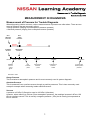
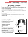
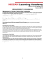
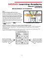
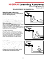
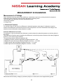
MEASUREMENT
IN TROUBLE
DIAGNOSIS
April 2008
Foreword
The information in this Training Manual should not be interpreted as a basis for
warranty or goodwill claims against Nissan Motor Co. (Australia) Pty. Ltd. (NMA)
unless so designated.
This Technical Training Manual is intended for use by NMA & Nissan Dealership
Technical Personnel. It is not designed for the use by press or for customer
distribution.
Before quoting any specifications be sure to check the relevant Service Manual
and Technical Bulletins.
Right for alteration to data and specifications at any time is reserved. Any such
alterations will be advised by Nissan through Technical and Sales Bulletins.
©2008 Nissan Motor Company (Australia) Pty. Ltd.
Inc. Victoria
Ref: Technical Training Department.
Measurement in Trouble Diagnosis.
Nissan Australia April 2008
MEASUREMENT IN DIAGNOSIS
Measurement of Pressure for Trouble Diagnosis
When diagnosing vehicle concerns, various measurements of pressure are often taken. There are two
types of pressure that we commonly refer to:
• Gauge pressure (ranging from atmospheric pressure upwards)
• Absolute pressure (ranging from a complete vacuum upwards).
Zero
Gauge
Pressure
Zero
Absolute
Pressure
Negative
Pressure
Complete
Vacuum
100 kPa
Positive
Pressure
Atmospheric
Pressure
60 kPa
0 kPa
Manifold
Vacuum
- petrol
@ idle
350 kPa
Fuel
Pressure
- petrol
1,200 kPa
3,100 kPa
Compression
Pressure
- petrol
Compression
Pressure
- Diesel
180,000 kPa
Common Rail
Diesel injection
pressure
Note: Not to scale
Gauge Pressure
This is relative to atmospheric pressure and is most commonly used in system diagnosis.
Absolute Pressure
This is measured from a perfect vacuum through to positive pressures. This is less commonly used
except for example when measuring intake manifold vacuum.
Vacuum
A pressure of 0 kPa G (Gauge) is equal to 100 kPa A (Absolute).
However, when referring to vacuum (from atmospheric pressure), the readings increase in kPa to 100
kPa at a perfect vacuum. This is actually a negative pressure (- kPa) but is usually just expressed as
kPa of vacuum.
1
Measurement in Trouble Diagnosis.
Nissan Australia April 2008
MEASUREMENT IN DIAGNOSIS
Measurement of the Fuel Pressure (Petrol Engines)
As part of an Engine no / poor running diagnosis, the Fuel Pressure is an important measurement to record
in order to narrow down the cause of a fault. Measuring Fuel Pressure will measure the pressure that the
fuel is under prior to entering the injector.
Obviously the Fuel won’t spray properly if the pressure is incorrect (too low). Also, the amount of fuel
entering the combustion chamber will be insufficient if the pressure is too low (Fuel starvation).
If the Fuel Pressure is too high, then the engine will have a rich running / excessive fuel consumption issue
Fuel system tests are:
• Pressure
• Residual Pressure Retention
Ensure there is sufficient fuel in the tank before conducting tests.
Fuel Pressure Release
On all systems, it is important to safely release residual fuel pressure before removing fuel hoses.
• Perform “FUEL PRESSURE RELEASE” with CONSULT II in Work Support Mode. Ensure that engine
stalls and will not restart.
• Without CONSULT II, remove the fuel pump fuse, run the engine until it stalls and ensure that it will not
restart.
WARNING: Great care must be taken to avoid fires when opening the fuel system.
Fuel Pressure Test on Return Systems
1. Install the Fuel Pressure gauge on the engine. Refer
to Section EC – “Basic Service” in the Service Manual
2. Switch Ignition ON. Ensure Fuel Pump activates &
then stops after a few seconds. Check for fuel leaks.
3. Start engine and read fuel pressure. Compare to
specifications in the Service Manual.
Check the following items if fuel pressure is too Low:
• Blocked filter or fuel pump pick up
• Restricted fuel lines
• Faulty pressure regulator.
Intake
Manifold
Pressure
Fuel
Damper
Pressure
Regulator
Note:
• If fuel pressure is LOW, carefully squeeze the return
line (resulting in blocking it) & watch a sharp & rapid
increase to approximately double the normal Fuel
Pressure spec. Only do this for a maximum of 3
seconds. If the pressure increase does occur the fuel
pressure regulator is faulty.
If not, either the level of fuel in the tank is low, the fuel
pump output is weak, a fuel line is blocked or the fuel
filter is blocked.
• If fuel pressure is too HIGH, either the pressure
regulator is faulty or the return line is restricted.
2
Fuel
Pressure
Gauge
Fuel Filter
* Not all models
Fuel
Return
Fuel Pump
(Filter and Sender Unit)
* Not all models
Fuel Tank
Measurement in Trouble Diagnosis.
Nissan Australia April 2008
MEASUREMENT IN DIAGNOSIS
Fuel Pressure Test on Return-less Systems
1. Install the Fuel Pressure gauge on the engine. Refer
to Section EC – “Basic Service” in the Service Manual
2. Switch Ignition ON. Ensure Fuel Pump activates &
then stops after a few seconds. Check for fuel leaks.
3. Start engine and read fuel pressure. Compare to
specifications in the Service Manual.
Injector Rail
With Injectors
Fuel
Damper
Check the following items if fuel pressure is too LOW:
• Blocked filter or fuel pump pick up
• Restricted fuel lines
• Faulty pressure regulator.
Note:
• DO NOT SQUEEZE OR CRIMP FUEL LINES!
• If fuel pressure is too HIGH, replace the pressure
regulator which is located in the fuel tank.
Fuel Tank
Fuel Pump
(Filter and
Sender Unit)
Pressure
Regulator
(Pre-set, non variable)
Fuel Return
Residual Pressure Retention (Both types of Fuel Systems)
Ensure that when the engine & fuel pump is switched OFF, fuel pressure is retained in the lines for the
specified period. Typically this should be no more than a 10% drop over 10 seconds.
If pressure is dropping away excessively, consideration needs to be given to the following items:
• Leakage in the reverse direction back to the tank.
• Leakage in the forward direction through leaking injectors (or fuel pressure regulator on Return Systems
only). If this is the case, the engine will be difficult to start & black smoke will be emitted from the exhaust.
Typical SST requirements for Fuel Pressure Testing
Adapter
KV 101118400
Adapter
KV 10117600 AUS
Gauge and Adapter
7211 and 7273
Fuel Line Removal
Tool
16441 6N210
3
Measurement in Trouble Diagnosis.
Nissan Australia April 2008
MEASUREMENT IN DIAGNOSIS
Measurement of Compression in the Cylinder Chamber
As part of an Engine no / poor running diagnosis, the Cylinder Compression is an important measurement to
record in order to narrow down the cause of a fault. Correct engine compression is a critical factor in good
engine operation, good fuel consumption and providing clean emissions.
Actual compression pressures will vary depending on the type and condition of the engine.
Typical range of compression pressures:
Engine
Compression kPa
Max variation
between cyls.
Cranking
RPM
Std
Minimum
Petrol – VQ40
1,275
981
98
300
Diesel Indirect Injection – TD42
2,942
2,452
294
200
Diesel Direct Injection – ZD30
2,942
2,452
294
200
Diesel Direct Injection – YD25
3,100
2,500
490
200
Compression Test Procedure
(All engine types)
Engine MUST be at operating temperature.
Ensure battery condition will enable correct cranking speed (monitor with CONSULT II). Use jumper battery
if necessary.
If the compression is below specifications:
• Check valve clearances
• Conduct wet-test (small qty. of oil added to Low cylinder):
• If compression increases, suspect rings/piston problem
• If compression remains same, suspect valves/cylinder head.
• If two adjacent cylinders remain Low, suspect head/gasket problem.
Petrol Engines
1. Remove fuel pump fuse, crank engine a few times to ensure engine won’t start
2. Remove; manifold collector (if required), ignition coils and spark plugs
3. Insert compression gauge
4. Switch ignition ON and depress accelerator pedal fully
NOTE: The Electronic Throttle (if fitted) will open with ignition switched ON.
5. Crank engine and after gauge stabilises, RECORD compression readings for each cylinder.
4
Measurement in Trouble Diagnosis.
Nissan Australia April 2008
MEASUREMENT IN DIAGNOSIS
Diesel Engines
1. Ensure engine is warmed thoroughly & then switch engine OFF.
2. Refer to section EM or EC of the Service Manual for correct pump or fuel system disabling procedure.
NOTE: On YD25 engines - remove injector connectors and carefully isolate with insulation tape. (Refer to
Service Manual Update Bulletin EM06-001).
3. Remove Glow Plugs (ensure dirt cannot enter engine and glow plugs are not knocked around)
4. Insert correct compression gauge adaptor for the engine.
NOTE: Engine can be permanently damaged if incorrect compression gauge adaptor is used.
5. Crank engine and after gauge stabilises, RECORD compression readings for each cylinder.
Diesel Engine SST’s for checking Compression
Refer to the right for the different glow plug hole adapter
tools required for measuring compression on diesel
engines.
NOTE:
Take care not to use the wrong adapter. Otherwise
severe engine damage will result.
Petrol Engines
Use any commercially available tools for checking
compression on petrol engines.
YD25 Engine
ED19600610
ZD30 Engine
ED19600620AUS
(DO NOT use in YD
engine or severe
damage will result)
TD Engines
ED19600600
5
Measurement in Trouble Diagnosis.
Nissan Australia April 2008
MEASUREMENT IN DIAGNOSIS
Measurement of Oxygen Content after Combustion
All modern petrol engines have Oxygen Sensors installed in the exhaust manifold. These sensors generate
a voltage signal & sends this voltage back to the ECM.
A varying amount of Oxygen seen by the sensor will create a varying voltage signal. The ECM sees this
varying voltage & then it MAKES AN ASSUMPTION ON HOW MUCH FUEL ENTERED THE
COMBUSTION CHAMBER.
If the Oxygen Sensor (O2S) measures a HIGH level of Oxygen;
This will tell the ECM the A/F Ratio was LEAN. Therefore on the engines next cycle the ECM will add
MORE Fuel.
If the Oxygen Sensor (O2S) measures a LOW level of Oxygen;
This will tell the ECM the A/F Ratio was RICH. Therefore on the engines next cycle the ECM will add
LESS Fuel.
Small Amount of Fuel (LEAN)
This condition will create a situation where the A/F mix will have a short burn time. There is not enough fuel
to make a long burn time. Since the small quantity of fuel has quickly burnt up, the burning will stop & there
will be a certain amount of Oxygen remaining amongst the exhaust gases.
These gases are expelled out the exhaust valve, the O2 Sensor samples these spent gases & there it will
see this remaining O2 content. This will create a voltage signal which indicates to the ECM that the amount
of fuel that was sprayed out of the injector was a small amount, therefore next cycle it will increase the
injection rate.
Large Amount of Fuel (RICH)
This condition will create a situation where the A/F mix will have a long burn time. There is now more fuel to
make a longer burn time. Since the larger quantity of fuel makes a longer burn time, nearly the entire O2
content will burn.
The spent gases left over in the combustion chamber will contain very little if any O2 content. These gases
are expelled out the exhaust valve, the O2 Sensor samples these spent gases & there it will see that there
is hardly any remaining O2 content. This will create a voltage signal which indicates to the ECM that the
amount of fuel that was sprayed out of the injector was a large amount, therefore next cycle it will decrease
the injection rate.
6
Measurement in Trouble Diagnosis.
Nissan Australia April 2008
MEASUREMENT IN DIAGNOSIS
Ideal Air Fuel Mix (14.7:1)
The right amount of Air to Fuel will result in an ideal
burn.
IDEAL 14.7:1
LEAN by Short Injection Duration
(Excess of Air to Fuel)
The injector is opened for a short period of time by the
ECM. Only a small amount of fuel enters the
combustion chamber. This results in a short burn time,
therefore some O2 content will be left over after the
burning has stopped. This left over content of O2 is
expelled & then seen by the O2 sensor. This signals to
the ECM that the mix was lean, therefore will result in
an increased rate of injection (more fuel) for the next
cycle.
SMALL INJECTION QUANTITY
LEAN by Fuel Starvation (Injection Duration OK)
(Excess of Air to Fuel)
Due to low fuel pressure / blocked filter / blocked
injectors etc, this results in a short burn time due to the
lack of fuel. This again results in some O2 content
being left over. This left over content of O2 is expelled &
then seen by the O2 sensor. This signals to the ECM
that the mix was lean, therefore will result in an
abnormal increase in the rate of injection for the next
cycle in order to compensate for the “lack of fuel”
condition.
7
FUEL STARVATION PROBLEM
Measurement in Trouble Diagnosis.
Nissan Australia April 2008
MEASUREMENT IN DIAGNOSIS
LEAN by Intake Air Leak (un-metered air)
(Injection Duration OK - Excess of Air to Fuel)
Due to an air leak on the intake (leaking intake manifold
gasket, hole in air intake tube etc.) the MAFS sensor
only measures a certain amount of air This signal is
sent to the ECM, therefore the ECM adds a specific
amount of fuel which is relevant to the amount of air
measured.
Air which is leaking through a hole or a leaky gasket is
added to the combustion chamber with an insufficient
amount of fuel. Combustion takes place but there is left
over O2 in the exhaust gases & therefore is seen by the
O2 sensor. This signals the ECM to increase the
injection rate above what it thinks is normal.
INTAKE AIR LEAK
AIR LEAKS!!
False LEAN Signal due to Exhaust Leak
(Injection Duration OK. Air/Fuel Ratio normal)
REMEMBER! If the O2 sensor sees Oxygen, it means
LEAN! Therefore if O2 leaks into an exhaust manifold
due to a cracked exhaust manifold or a leaking exhaust
manifold gasket, the false O2 content will make the
ECM increase the injection rate – EVEN IF THE
INJECTION RATE WAS PERFECT!
EXHAUST MANIFOLD LEAK
False LEAN Signal due to Spark Missfire
(Injection Duration OK. Air/Fuel Ratio normal)
REMEMBER! NO spark means NO burn. Even if TOO
MUCH fuel entered the combustion chamber, if it
doesn’t burn, neither does the O2 content. Unburnt O2
means LEAN! As a result the ECM increases the
injection rate to add more fuel to an engine that doesn’t
need anymore fuel.
8
X
NO SPARK
Measurement in Trouble Diagnosis.
Nissan Australia April 2008
MEASUREMENT IN DIAGNOSIS
RICH
(Normal Air Quantity with Excess Fuel)
If there is an excess amount of fuel added (leaking
injectors or excessive injection duration etc.), not all of
the fuel will burn because in this case the burning will
stop due to all the oxygen being burnt up. RAW FUEL
WITHOUT OXYGEN WILL NOT BURN ON IT’S OWN.
The excess fuel will be expelled out of the exhaust
valve, however the reason why the O2 sensor will
indicate RICH is because it cannot sense any O2 in the
expelled exhaust gases. NOT because of the raw fuel
left over.
AN OXYGEN SENSOR CAN ONLY SEE OXYGEN.
It cannot see raw fuel.
RUNNING RICH / FLOODING
Using Air Fuel Alpha in CONSULT II to indicate measured Oxygen Content
Display A/F ALPHA in DATA MONITOR or DATA MONITOR (SPEC) CONSULT. If the A/F Alpha shows a
reading close to 100%, (typically 95% ~ 105%) then the engine is running close to or at it’s originally
programmed map.
I.e.; The ECM see no problems with the content of left over O2 it’s measuring in the exhaust gases. The
balance of Fuel Quantity to Air Quantity in the engine is normal.
9
Measurement in Trouble Diagnosis.
Nissan Australia April 2008
MEASUREMENT IN DIAGNOSIS
Basic Principles of Electrical
Given that Electricity can’t be seen, it can be difficult to
determine electrical system faults.
Therefore if Electricity was likened to water flow, it may
assist with understanding how to diagnose electrical
faults.
12V
Battery
Digital
Multi
Meter
Light
Globe
1. Normally Operating Circuit
Here the water flows from the tap (battery) through a
hose (wiring). A pressure gauge (voltmeter) has been
tapped into the hose to measure the line pressure.
The spray nozzle (light globe) at the end of hose
shows a working circuit.
Due to the restriction (globe filament) there is a certain
amount of pressure build up in the line. This is
measured by the pressure gauge (voltmeter). Some of
the pressure is seen by the gauge, the remainder of the
pressure escapes through the nozzle.
2. No Ground Connection
Here the 2nd diagram shows a circuit which can be
likened to having no ground connection (blockage in
hose). Therefore the only choice the pressure has is to
follow the path offered by the gauge (voltmeter).
However the gauge does no allow any pressure to
escape, but it does show the full supply pressure.
3. Short to Ground
Here the 3rd diagram shows there is no restriction (load
such as a globe filament) the flow runs out the end of
the pipe (directly from positive back to negative).
Therefore YES, there is the flow of current present, but
it cannot be seen by the pressure gauge (voltmeter).
The path offered by the gauge (voltmeter) is too
restrictive. It’s easier for it to fully escape from the end
of the hose.
If this was really a flow of electrical current, the fuse
would blow & shut down the flow all together.
10
12V
Battery
Digital
Multi
Meter
No Ground
Connection
12V
Battery
Digital
Multi
Meter
Short to
Ground
Measurement in Trouble Diagnosis.
Nissan Australia April 2008
MEASUREMENT IN DIAGNOSIS
Measurement of Voltage
Since electricity can’t be seen by the naked eye, technicians need to rely on key electrical concepts to
understand how electrical circuits function and assist in locating faults.
Two important concepts that are often misunderstood are:
• Electrical Pressure
• Voltage Drop
1. Electrical Pressure
For current to flow in any circuit, a difference in electrical pressure must exist. A Voltmeter is used to
measure the difference in electrical pressure at any two points in a circuit. Remember that Voltage in an
electrical circuit is likened to water pressure in a pipe.
Pressure Difference in a Circuit
For example, in the circuit below the Voltmeter is used to detect the electrical pressure at various points in
the circuit.
The Voltmeter’s Positive lead is detecting the difference in electrical pressure between the battery Negative
terminal, to four other circuit locations.
The electrical pressure difference between the:
• (A) Battery Positive terminal and Battery Negative terminal – 12V
• (B) Switch output terminal and Battery Negative terminal – 11.9 Volts
• (C) Bulb power side and Battery Negative terminal – 11.9 volts
• (D) Bulb ground side and Battery Negative terminal – 0 Volts
Notice that the full battery voltage (or pressure) drops to 0 Volts as the circuit approaches ground.
11
Measurement in Trouble Diagnosis.
Nissan Australia April 2008
MEASUREMENT IN DIAGNOSIS
1. Electrical Pressure (Cont’d…./)
Here is the same electrical circuit with a fault. The wiring is frayed & current has to now make it’s way
through the resistance which is caused by the frayed / damaged wire.
So now, the electrical pressure difference between the:
• (A) Battery Positive terminal and Battery Negative terminal – 12V
• (B) Switch output terminal and Battery Negative terminal – 11.9 Volts
• (C) Bulb power side and Battery Negative terminal – 7.9 Volts
• (D) Bulb ground side and Battery Negative terminal – 0 Volts
12
Measurement in Trouble Diagnosis.
Nissan Australia April 2008
MEASUREMENT IN DIAGNOSIS
2. Voltage Drop
As electrical current flows through any circuit or device for work to be done, there must be a Voltage Drop
across that circuit. Voltage must be dropped from supply voltage to zero at the ground point.
However there are instances when additional Voltage Drop may be inadvertently built into a circuit through
loose or dirty connections, particularly in the ground circuit. Any additional Voltage Drop robs the circuit of
energy, reducing its effectiveness.
To do a continuity or resistance test with an Ohmmeter does not confirm the high load performance of a
circuit and a Voltage Drop test should be performed.
Voltage Drop in a Circuit
For example, in the circuit below the Voltmeter is used to detect the voltage drop across various
components in the circuit.
The Voltmeter’s leads are detecting the difference in electrical pressure between the two points they are
connected to at any one time.
The Voltage Drop across the:
• (A) Battery Positive lead to the Switch Input – 0V
• (B) Switch input & output terminals – 0.1 Volts
• (E) Wire from switch output to bulb input – 0 volts
• (C) Bulb – 9.9 Volts (example only, will always vary dependant on bulb type)
• (D) Ground circuit, from bulb output to Ground – 0 Volts.
• (F) Directly across the battery shows the full difference – 12V
13
Measurement in Trouble Diagnosis.
Nissan Australia April 2008
MEASUREMENT IN DIAGNOSIS
2. Voltage Drop (Cont’d…./)
Here is the same electrical circuit with a fault. The wiring is frayed & current has to now make it’s way
through the resistance which is caused by the frayed / damaged wire.
So now, the Voltage Drop across the:
• (A) Battery Positive lead to the Switch Input – 0V
• (B) Switch input & output terminals – 0.1 Volts
• (E) Wire from switch output to bulb input – 4 volts
• (C) Bulb – 5.9 Volts (example only, will always vary dependant on bulb type)
• (D) Ground circuit, from bulb output to Ground – 0 Volts.
• (F) Directly across the battery shows the full difference – 12V
14
Measurement in Trouble Diagnosis.
Nissan Australia April 2008
MEASUREMENT IN DIAGNOSIS
2. Voltage Drop (Cont’d…./)
Here is the same electrical circuit with yet another fault. In this case the wiring is OK, but now there is a bad
ground contact.
So now, the Voltage Drop across the:
• (A) Battery Positive lead to the Switch Input – 0V
• (B) Switch input & output terminals – 0.1 Volts
• (E) Wire from switch output to bulb input – 0 volts
• (C) Bulb – 5.9 Volts (example only, will always vary dependant on bulb type)
• (D) Ground circuit, from bulb output to Ground – 4 Volts.
• (F) Directly across the battery shows the full difference – 12V
POOR GROUND CONTACTS ARE THE MOST COMMON CAUSE OF ELECTRICAL
FAULTS. THIS IS THE COMMON CAUSE OF DTC’s SUCH CAN U1000 & U1001 TO BE
LOGGED.
15
Measurement in Trouble Diagnosis.
Nissan Australia April 2008
MEASUREMENT IN DIAGNOSIS
Ground Connection Voltage Drop
When tracking down an electrically related fault it is important to do a Voltage Drop test across ground
connections.
This is very important in high current circuits like the starting and charging system, but should not be
neglected in lower current electronic systems.
The ground should be tested with the circuit operating under as much electrical load as possible.
• Connect the Positive Voltmeter lead to the ground terminal
• Connect the Negative Voltmeter lead to the grounding bolt or another clean ground area
• Operate the circuit under load (including turning on accessories or cranking the engine)
• Measure Voltage Drop across the connection.
Repairing Grounds
When repairing or confirming ground connections, it is important to remove the bolt, inspect and clean the
mating surfaces and then torque the bolt securely.
Ground cleaning procedure
Check for added-on accessories and any modifications to the ground circuits
Check for proper crimps and that all wires are securely fastened.
Voltage Drop Limits
Wire – negligible (< 0.001 Volts)
Ground connection – Approx. 0.1 Volts
Switch contacts – Approx. 0.3 Volts.
16
Measurement in Trouble Diagnosis.
Nissan Australia April 2008
MEASUREMENT IN DIAGNOSIS
N16 Hatch Brake Lamp Failsafe Strategy
An interesting application of applying a change in
Voltage Drop is found on the N16 Pulsar Ser II Hatch
(Models with Electric Throttle Control only).
These vehicles are built for the European market and
have a Failsafe strategy if both brake lamp bulbs are
not working. If this occurs, the ECM will enter a Failsafe
Mode and the engine will operate with a significant
reduction in performance (further details are found on
STB EC05-011). This situation will prompt the driver to
have the vehicle checked.
Like most vehicles, the ECM monitors the application of
the brakes for fuel control. Using the same input, it also
monitors small changes in Voltage Drop in the brake
lamp circuit to determine if all the brake lamps are
working.
Essentially, the brake lamp circuit contains two groups
of resistances in series, creating a Voltage Divider
circuit with the Brake Signal input to the ECM.
Rear Brake Lights OK
The 1st diagram to the above right shows a normal
brake light circuit.
The current from the battery travels through the close
brake pedal switch contacts (switch contacts always
have a slight resistance in them) & then it has a choice
of travelling to the rear brake lights or to the ECM. The
ECM at this point sees the voltage pressure in the
circuit. So the ECM knows if the brakes are being
applied or not.
However, seeing as all the Brake light globes are OK,
the current will flow to ground as this circuit has far less
resistance. So the ECM is NOT going to see the full
12V.
Rear Brake Light Globes OPEN Circuit
(Blown globes)
In this case, the rear brake light circuit has a much
higher resistance. The current can only travel to ground
through the LED rear window brake light. So the voltage
pressure build up in the circuit is sensed by the ECM
(ECM reads a higher voltage). So the ECM now
realises that there are no brake lights & it drives in
failsafe mode until the fault is rectified.
NOTE: A bad ground connection or corroded bulb
connections can cause the same condition!
17