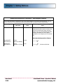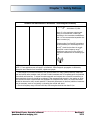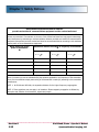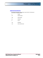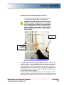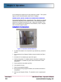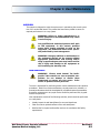
1
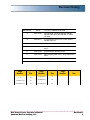
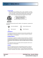
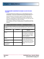
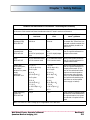
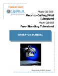
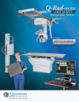
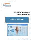
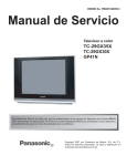
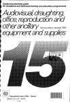
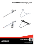
Model QW-400 Vertical Wall Frame Models QW-420, QW-420-S, and QW-420-D Vertical Wall Stand Operator’s Manual Manual Part No. DC30-039 Revision H This manual is copyrighted and all rights are reserved. No portion of this document may be copied, photocopied, reproduced, translated, or reduced to any electronic medium or machine readable form without prior consent in writing from Quantum Medical Imaging, LLC. (QMI) Copyright© 2012 QMI Quantum Medical Imaging, LLC Division of Carestream 2002-B Orville Drive North Ronkonkoma, New York 11779 USA Phone: (631) 567-5800 Fax: (631) 567-5074 E-mail: [email protected] www.quantummedical.net Made in U.S.A. Revision History REVISION DATE TYPE OF MODIFICATION A 2004-03-01 Initial Release. Combined Models QW-400, QW-420, QW-420-D and QW-420-S. Added CE mark B 2009-09-11 Incorporated ECOs 2123, 2173 & 2199 and updated CE mark C 2009-10-30 Incorporated ECOs 1824, 2015, 2167 D 2010-05-21 Incorporated ECOs 2231, 2266, 2285, 2286, 2309 E 2010-12-23 Incorporated ECOs 2399, 2432 F 2011-09-16 Revised safety mark to ETL, incorporated ECO 2482 G 2011-12-29 Added EU Representative Information H 2012-05-22 Added IEC 60601-1: 2005 Page Number Rev Page Number Rev i - iv H 3-1 thru 3-8 H 1-1 thru 1-14 H 4-1 thru 4-4 H 2-1 thru 2-12 H 5-1 thru 5-8 H Wall Stand/Frame - Operator’s Manual Quantum Medical Imaging, LLC Page Number Rev Revision H i Revision History THIS PAGE INTENTIONALLY LEFT BLANK Revision H ii Wall Stand/Frame - Operator’s Manual Quantum Medical Imaging, LLC Table of Contents CHAPTER 1 SAFETY NOTICES GENERAL SAFETY INFORMATION ......................................................... 1-3 WARNINGS, CAUTIONS, NOTES .............................................................1-3 REGULATORY COMPLIANCE ................................................................. 1-5 CLASSIFICATION ........................................................................... 1-6 COMPATIBILITY ............................................................................. 1-6 INTENDED OPERATOR ................................................................... 1-6 TRAINING ..................................................................................... 1-6 ACCOMPANYING DOCUMENTATION ................................................ 1-7 APPLICABLE STANDARDS ............................................................... 1-7 ENVIRONMENTAL PROTECTION ........................................................... 1-7 ELECTROMAGNETIC COMPATIBILITY (EN 60601-1-2:2007/IEC 60601-1-2:2007) ............................................ 1-8 ABBREVIATION DEFINITION .............................................................. 1-13 CHAPTER 2 GENERAL INFORMATION OVERVIEW .......................................................................................... 2-3 KEY FEATURES .............................................................................. 2-3 INTENDED USE .............................................................................. 2-4 RECEPTOR OPTIONS ...................................................................... 2-4 MAIN COMPONENTS - MODEL QW-420 ................................................. 2-6 MAIN COMPONENTS - MODEL QW-420-S .............................................. 2-9 MAIN COMPONENTS - MODEL QW-420-D ............................................ 2-10 MAIN COMPONENTS - MODEL QW-400 ............................................... 2-11 CHAPTER 3 OPERATION OVERVIEW .......................................................................................... 3-3 OPERATION INSTRUCTIONS - RECEPTOR CONTROL HANDLE ........... 3-3 OPTIONAL PATIENT OVERHEAD HANDGRIP OPERATION ................. 3-5 MODELS QW-400, QW-420, AND QW-420-S CASSETTE TRAY OPERATION .......................................................................... 3-6 Loading Cassette Tray (Quantum Type) ..................................... 3-6 Loading Cassette Tray (Poersch Type) ....................................... 3-7 PORTABLE DIGITAL RECEPTOR TRAY OPERATION ........................... 3-8 MODEL QW-420-D (WITH FIXED DIGITAL RECEPTOR) OPERATION .................................................................................. 3-8 Wall Stand/Frame - Operator’s Manual Quantum Medical Imaging, LLC Revision H iii Table of Contents CHAPTER 4 USER MAINTENANCE OVERVIEW .......................................................................................... 4-3 USER MAINTENANCE ..................................................................... 4-3 Cleaning .................................................................................. 4-4 CHAPTER 5 - WARRANTY INFORMATION WARRANTY STATEMENT ...................................................................... 5-3 WARRANTY EXCLUSIONS ..................................................................... 5-5 BUYER’S REMEDIES ............................................................................. 5-6 WARRANTY RETURN PROCEDURE ........................................................ 5-6 EQUIPMENT IN TRANSIT ..................................................................... 5-6 VOIDING WARRANTY .......................................................................... 5-7 Revision H iv Wall Stand/Frame - Operator’s Manual Quantum Medical Imaging, LLC Chapter 1 SAFETY NOTICES 1-1 1-2 Chapter 1 Safety Notices GENERAL SAFETY INFORMATION Quantum products are designed to meet stringent safety standards. All medical electrical equipment requires proper installation, operation, and maintenance (particularly with regard to safety). It is vital that the user read, understand, note, and where applicable, strictly observe all Warnings, Cautions, Notes and Safety markings within this document and on the equipment, and that the user strictly follow all safety directions in this manual to help ensure the safety of users and patients. Every reasonable precaution has been taken during manufacture to safeguard the health and safety of persons who will operate this equipment. The following precautions must be observed at all times. WARNINGS, CAUTIONS, NOTES The following samples show how warnings, cautions, and notes appear in this document. The text explains their intended use. WARNING CAUTION NOTE Indicates injury or death is possible if the instructions are not obeyed. Instructs users to refer to documentation if displayed without warning text. Indicates that damage to equipment is possible if the instructions are not obeyed. Notes provide advice and highlight unusual points. A note is not intended as an instruction. The purpose of safety icons, such as those shown below, is to indicate at a glance the type of caution, warning or danger. WARNING Ionizing radiation: indicates the possibility of increased levels of radiation. WARNING Dangerous voltage: indicates the presence of high voltage. WARNING Warning, hot surface. Wall Stand/Frame - Operator’s Manual Quantum Medical Imaging, LLC Revision H 1-3 Chapter 1 Safety Notices WARNING Quantum Medical Imaging, LLC disclaims all responsibility from any injury resulting from improper application of this equipment. This equipment is sold to be used exclusively under the prescribed direction of a person who is licensed by law to operate equipment of this nature. This equipment must be used in accordance with all safety procedures described in this manual and must not be used for purposes other than those described herein. In the United States, Federal law restricts this device to sale, distribution, and use by or on order of a licensed physician. Quantum Medical Imaging, LLC cannot assume responsibility for any malfunctioning of this equipment resulting from improper operation, maintenance, or repair, or from damage or modification of its components. Failure to observe these warnings may cause serious injuries. WARNING X-rays are hazardous to both patient and operator unless established safe exposure factors and operating instructions are observed. Only qualified and authorized personnel shall operate this system. In this context, qualified means those legally permitted to operate this equipment in the jurisdiction in which the equipment is being used, and authorized means those authorized by the authority controlling the use of the equipment. Full use must be made of all radiation protection features, devices, systems, procedures and accessories. It is important that everyone having anything to do with x-radiation be properly trained and fully acquainted with the recommendations of the National Council on Radiation Protection and Measurements as published in NCRP Reports available from NCRP Publications, 7910 Woodmont Avenue, Suite 800, Bethesda, Maryland 20814-3095 (www.ncrp.com), and of the International Commission on Radiological Protection (www.icrp.org), and take adequate steps to protect against injury. Revision H 1-4 Wall Stand/Frame - Operator’s Manual Quantum Medical Imaging, LLC Chapter 1 Safety Notices WARNING X-ray equipment may cause injury if used improperly. The instructions contained in this manual must be read and followed when operating this unit. Personal radiation monitoring and protective devices are available. You are urged to use them to protect against unnecessary x-ray exposure. REGULATORY COMPLIANCE This certified Quantum Medical Imaging, LLC medical device has been designed, manufactured, and calibrated to comply with governing Federal Regulations 21 CFR Subchapter J and the performance standards attendant thereto. Upon installation, all certified products require the filing of Form FD-2579 "Report of Assembly of a Diagnostic X-ray System" by the assembler (i.e., the installer) with the appropriate agencies; the "Installation Quality Assurance Checklist" must also be completed and properly distributed upon installation. A copy of each form (pink copy) is provided to the user. The installation report is completed by the installer and returned to Quantum Medical Imaging, LLC. Those responsible for the planning of x-ray equipment installations must be thoroughly familiar and comply completely with NCRP Report No. 49, "Structural Shielding Design and Evaluation for Medical Use of X-Rays and Gamma Rays of Energies up to 10 MeV", as revised or replaced in the future. Those authorized to operate, test, participate in or supervise the operation of the equipment must be thoroughly familiar and comply completely with the currently established safe exposure factors and procedures described in publications such as Subchapter J of Title 21 of the Code of Federal Regulations, "Diagnostic X-Ray Systems and Their Major Components," and NCRP Report No. 102, “Medical X-Ray, Electron Beam and Gamma Ray Protection for Energies Up to 50 MeV—Equipment Design and Use” as revised or replaced in the future. This equipment must only be used in rooms that comply with all applicable laws or regulations that have the force of law, concerning electrical safety for this type of equipment. Scheduled maintenance is essential to the assurance of continued integrity of this equipment with respect to regulatory compliance. The continuance of certified performance to the regulatory standard is incumbent upon the user's diligent conformance to recommended maintenance instructions. Complies with FDA Center for Devices and Radiological Health (CDRH) - Title 21 CFR Subchapter J, and EC Directive 93/42/EEC for Medical Devices. Wall Stand/Frame - Operator’s Manual Quantum Medical Imaging, LLC Revision H 1-5 Chapter 1 Safety Notices CLASSIFICATION This product has been classified as Class I, Type B. Equipment not suitable for use in the presence of a flammable anesthetic mixture of air with oxygen or with nitrous oxide. Protection against Harmful Ingress of Water (Ordinary), enclosed equipment without protection against ingress of liquids. MEDICAL ELECTRICAL EQUIPMENT WITH RESPECT TO ELECTRIC SHOCK, FIRE, MECHANICAL HAZARDS ONLY CONFORMS TO UL STD 60601-1 CERTIFIED TO CAN/CSA STD C22.2 NO. 601.1 The following symbols may be used for marking on this equipment or equipment documentation: Non-ionizing Radiation Protective Earth (ground) Earth (ground) Type B Equipment COMPATIBILITY The equipment described in this manual must only be used in combination with other equipment or components if these are expressly recognized by Quantum Medical Imaging, LLC as compatible. INTENDED OPERATOR This equipment is intended to be installed, used and operated only in accordance with the safety procedures given within this manual for the purpose for which it was designed. Before attempting to work with this equipment, read, understand, note and strictly observe all warnings, cautions and safety markings on the equipment. Users include those persons who actually handle the equipment and those who have authority over the equipment. TRAINING Users of this equipment shall have received adequate training on its safe and effective use before attempting to work with the equipment. Training requirements may vary from country to country. The User shall make sure that training is received in accordance with local laws or regulations that have the force of law. Revision H 1-6 Wall Stand/Frame - Operator’s Manual Quantum Medical Imaging, LLC Chapter 1 Safety Notices ACCOMPANYING DOCUMENTATION The documentation consists of a User manual (this document) and related documentation: • Service Manual P/N DC30-040: Contains technical and service documentation for this product, including installation and configuration instructions to be performed by qualified persons The documentation shall be kept with the system for easy reference. APPLICABLE STANDARDS This equipment complies with the following regulatory standards: • EN 60601-1: 1990 + A1:1993 + A2:1995 + A13:1996 • IEC 60601-2-32: 1994 • CAN/CSA-C22.2 No. 601.1-M90, 2005 (Medical Electrical Equipment, part 1: General Requirements for Safety) • UL 60601-1, 1st Edition, 2006-04-26 (Medical Electrical Equipment, part 1: General Requirements for Safety) • IEC 60601-1 Medical electrical equipment, Part 1: General requirements for safety • IEC 60601-1-2: 2007 EU Authorized Representative: Carestream Health France 1, rue Galilée 93192 NOISY-LE-GRAND CEDEX France ENVIRONMENTAL PROTECTION This equipment contains certain materials and chemical compounds incidental to the manufacture of electrical and electronic equipment, and improper "end-of-life" disposal of such equipment can result in environmental contamination. Therefore, this equipment should not be disposed of as ordinary household waste, but should instead be delivered to a designated electrical and electronic waste disposal or recycling center. For further information on disposing of electrical and electronic waste, contact the cognizant authority within the jurisdiction. Wall Stand/Frame - Operator’s Manual Quantum Medical Imaging, LLC Revision H 1-7 Chapter 1 Safety Notices ELECTROMAGNETIC COMPATIBILITY (EN 60601-1-2:2007/IEC 606011-2:2007) The vertical wall stands are intended for use in the electromagnetic environment specified below. As such, the vertical wall stands must be installed and put into service according to the information provided in the accompanying Service Manual. Portable and mobile RF communications equipment can affect medical electrical equipment. It is therefore recommended that the operation of equipment of this type, such as mobile telephones, cordless microphones and other similar mobile radio equipment, be restricted from the vicinity of this device. Use of accessories, transducers and cables, other than those specified in the accompanying documents, may result in increased emissions or decreased immunity of the equipment. Guidance and manufacturer's declaration - electromagnetic emissions The vertical wall stand is intended for use in the electromagnetic environment specified below. The customer or the user of the vertical wall stand should assure that it is used in such an environment. Emissions test Compliance Electromagnetic environment guidance RF emissions CISPR 11 Group 1 The vertical wall stand uses RF energy only for their internal functions. Therefore, the RF emissions are very low and are not likely to cause any interference in nearby electronic equipment. RF emissions CISPR 11 Class A Harmonic emissions IEC 61000-3-2 Class A Voltage fluctuations/ flicker emissions IEC 61000-3-3 Complies The vertical wall stand is suitable for use in all establishments other than domestic and those directly connected to the public low-voltage power supply network that supplies buildings used for domestic purposes. Revision H 1-8 Wall Stand/Frame - Operator’s Manual Quantum Medical Imaging, LLC Chapter 1 Safety Notices Guidance and manufacturer's declaration - electromagnetic immunity The vertical wall stand is intended for use in the electromagnetic environment specified below. The customer or the user of the vertical wall stand should assure that it is used in such an environment. Immunity test IEC 60601 test level Compliance level Electromagnetic environment - guidance Electrostatic discharge (ESD) IEC 61000-4-2 ±6 kV contact ±8 kV air ±6 kV contact ±8 kV air Floors should be wood, concrete or ceramic tile. If floors are covered with synthetic material, the relative humidity should be at least 30 %. Electrical fast transient/burst IEC 61000-4-4 ±2 kV for power supply lines ±1 kV for input/output lines ±2 kV for power supply lines ±1 kV for input/output lines Mains power quality should be that of a typical commercial or hospital environment. Surge IEC 61000-4-5 ±1 kV differential mode ±2 kV common mode ±1 kV differential mode ±2 kV common mode Mains power quality should be that of a typical commercial or hospital environment. Voltage dips, short interruption, and voltage variations on power supply input lines IEC 60601-4-11 < 5 % UT (>95 % dip in UT) for 0.5 cycle < 5 % UT (>95 % dip in UT) for 0.5 cycle 40 % UT (60 % dip in UT) for 5 cycles 40 % % UT (60 % dip in UT) for 5 cycles 70 % UT (30 % dip in UT) < 5 % UT (> 95 % dip in UT) for 5 s 70 % UT (30 % dip in UT) < 5 % UT (> 95 % dip in UT) for 5 s Mains power quality should be that of a typical commercial or hospital environment. If the user of the vertical wall stand requires continued operation during power mains interruptions, it is recommended that the vertical wall stand be powered from an uninterruptible power supply or battery. 3 A/m 3 A/m Power frequency (50/60 Hz) IEC 61000-4-8 Power frequency magnetic fields should be at levels characteristic of a typical location in a typical commercial or hospital environment NOTE: UT is the A.C. mains voltage prior to application of the test level. Wall Stand/Frame - Operator’s Manual Quantum Medical Imaging, LLC Revision H 1-9 Chapter 1 Safety Notices Guidance and manufacturer's declaration - electromagnetic immunity The vertical wall stand is intended for use in the electromagnetic environment specified below. The customer or the user of the vertical wall stand should assure that it is used in such an environment. Immunity test IEC 60601 test level Compliance level Electromagnetic environment - guidance Portable and mobile RF communications equipment should be used no closer to any part of the vertical wall stand, including cables, than the recommended separation distance calculated from the equation applicable to the frequency of the transmitter. Recommended separation distance Conducted RF IEC 61000-4-6 3 Vrms 150 kHz to 80MHz 3 Vrms Radiated RF IEC 61000-4-3 3 V/m 80 MHz to 2,5 GHz 3 V/m Revision H 1-10 d 1,2 P d 1,2 P , 80 MHz to 800 MHz Wall Stand/Frame - Operator’s Manual Quantum Medical Imaging, LLC Chapter 1 Safety Notices Guidance and manufacturer's declaration - electromagnetic immunity d 2,3 P , 800 MHz to 2,5 GHz where P is the maximum output power rating of the transmitter in watts (W) according to the transmitter manufacturer and d is the recommended separation distance in metres (m). Field strengths from fixed RF transmitters, as determined by an electromagnetic site surveya, should be less than the compliance level in each frequency range.b Interference may occur in the vicinity of equipment marked with the following symbol: NOTE 1 At 80 MHz and 800 MHz, the higher frequency range applies. NOTE 2 These guidelines may not apply in all situations. Electromagnetic propagation is affected by absorption and reflection from structures, objects and people. a Field strengths from fixed transmitters, such as base stations for radio (cellular/cordless) telephones and land mobile radios, amateur radio, AM and FM radio broadcast and TV broadcast cannot be predicted theoretically with accuracy. To assess the electromagnetic environment due to fixed RF transmitters, an electromagnetic site survey should be considered. If the measured field strength in the location in which the vertical wall stand is used exceeds the applicable RF compliance level above, the vertical wall stand should be observed to verify normal operation. If abnormal performance is observed, additional measures may be necessary, such as re-orienting or relocating the vertical wall stand. b Over the frequency range 150 kHz to 80 kHz, field strengths should be less than 3 V/m. Wall Stand/Frame - Operator’s Manual Quantum Medical Imaging, LLC Revision H 1-11 Chapter 1 Safety Notices Recommended separation distances between portable and mobile RF communications equipment and the vertical wall stand The vertical wall stand is intended for use in an electromagnetic environment in which radiated RF disturbances are controlled. The customer or the user of the vertical wall stand can help prevent electromagnetic interference by maintaining a minimum distance between portable and mobile RF communications equipment (transmitters) and the vertical wall stand as recommended below, according to the maximum output power of the communications equipment. Rated maximum output power of transmitter W Separation distance according to frequency of transmitter m 150 kHz to 80 MHz d 1,2 P 80 MHz to 800 MHz d 1,2 P 800 MHz to 2,5 GHz d 2,3 P 0,01 0,12 0,12 0,23 0,1 0,38 0,38 0,73 1 1,2 1,2 2,3 10 3,8 3,8 7,3 100 12 12 23 For transmitters rated at a maximum output power not listed above, the recommended separation distance d in metres (m) can be estimated using the equation applicable to the frequency of the transmitter, where P is the maximum output power rating of the transmitter in watts (W) according to the transmitter manufacturer. NOTE 1: At 80 MHz and 800 MHz, the separation distance for the higher frequency range applies. NOTE 2: These guidelines may not apply in all situations. Electromagnetic propagation is affected by absorption and reflection from structures, objects and people. Revision H 1-12 Wall Stand/Frame - Operator’s Manual Quantum Medical Imaging, LLC Chapter 1 Safety Notices ABBREVIATION DEFINITION The following abbreviations and acronyms may be found in this document. Their definition is explained below. A Ampere DR Digital Receptor hPa Hecto-Pascals kg Kilograms lb Pound mm Millimeters Vdc Volts, Direct-Current Wall Stand/Frame - Operator’s Manual Quantum Medical Imaging, LLC Revision H 1-13 Chapter 1 Safety Notices THIS PAGE INTENTIONALLY LEFT BLANK Revision H 1-14 Wall Stand/Frame - Operator’s Manual Quantum Medical Imaging, LLC Chapter 2 GENERAL INFORMATION 2-1 2-2 Chapter 2 General Information OVERVIEW NOTE: The user should read this manual in its entirety prior to using this equipment. It should be kept in a location near the equipment and be readily accessible to those who operate it. This document is intended to assist users in the safe and effective operation of the equipment described herein. Pay special attention to all the information described in the Safety section (refer to Chapter 1, SAFETY NOTICES). This manual is written for trained users of Quantum Medical Imaging, LLC’s Vertical Wall Frame, Model QW-400; Vertical Wall Frame, Model QW-420; Vertical Non-Tilting Digital Image Receptor Holder, Model QW-420-D; and Vertical Wall Stand with SideMounted Receptor Cabinet, Model QW-420-S (hereinafter referred to as the vertical wall stand), and for authorized field service personnel. Quantum Medical Imaging, LLC assumes no liability for use of this document if any unauthorized changes to the content or format have been made. This manual provides information for operating and maintaining the vertical wall stand. It is imperative that all safety procedures described in this manual be strictly adhered to in order to ensure the safety of both patient and user. KEY FEATURES The key features of the vertical wall stand are as follows: • Accommodates all upright exams • Easy installation • Fail-safe electromagnetic locks for image receptor vertical motion • Model QW-400 receptor travel: 1155.7 mm (45.5 in.) with 356 mm x 432 mm (14 in. x 17 in.) image receptor, and 546.1 mm (21.5 in.) with 356 mm x 914 mm (14 in. x 36 in.) image receptor • Model QW-420 receptor travel: 1524 mm (60.0 in.) with 356 mm x 432 mm (14 in. x 17 in.) film receptor cabinet and 1041.4 mm (41.0 in.) with 356 mm x 914 mm (14 in. x 36 in.) film receptor cabinet • Model QW-420-S receptor travel: 1511.3 mm (59.5 in.) with 14 in. x 17 in. fixed grid image receptor and 1537 mm (60.5 in.) with 356 mm x 432 mm(14 in. x 17 in.) moving grid image receptor • Model QW-420-D receptor travel: 1537 mm (60.5 in.) typical, when installed with Q-DRT-CR, Q-DRT-CL, Q-DRT-CR-R, Q-DRT-CL-R, Q-DRTDRXR-R, Q-DRT-DRXL-R detector trays • Model QW-420 with Canon CXDI-50G portable receptor travel: 1524 mm (60 in.) Wall Stand/Frame - Operator’s Manual Quantum Medical Imaging, LLC Revision H 2-3 Chapter 2 General Information This product is intended to be used and operated only in accordance with the safety procedures given within this manual for the purpose for which it was designed. The intended use is given below. Nothing stated in this manual reduces user's professional responsibilities for sound judgment and best practice. INTENDED USE The vertical wall stand is intended for use as a support structure used to position a radiographic image receptor during a radiographic procedure. Inasmuch as the Wallstand is designed with 1.2 mm AL beam attenuation characteristics, the operator, when using accessories which present additional beam attenuation, should consider their impact on imaging results. Use of the equipment for purposes other than those intended and expressly stated by the manufacturer, as well as incorrect use or operation, may relieve the manufacturer or his agent from all or some of the responsibility for resultant noncompliance, damage or injury. NOTE: When the vertical wall stand is equipped with a digital receptor (DR) panel, this manual is incomplete without the Installation & Operation Manual shown in Table 2-1, which corresponds to the receptor option shipped with the system. Prior to operating this product, the user must become familiar with information provided therein. RECEPTOR OPTIONS The following table defines digital imaging receptor options available for the vertical wall stand, including references to ancillary documentation which supports the installation and operation of each receptor listed. The appropriate manual is shipped with each vertical wall stand. Table 2-1: Compatible Receptor Options Used On (Wall Stand Model) Reference Number (see Figure 2-1) Varian 4343R non-portable DR panel QW-420-D Q-FDR-V-R, Q-FDR-V-L DC30-110 Canon CXDI-40G COMPACT, non-portable DR panel QW-420-D Q-FDR-C-R, Q-FDR-C-L DC30-110 Agfa DX-D 4336R Portable DR panel, rotating tray QW-420-D Q-DRT-VR-R, Q-DRT-VL-R DC30-092 Canon CXDI-50G Portable DR panel, non-rotating tray QW-420-D Q-DRT-CR, Q-DRT-CL DC30-092 Option Type Revision H 2-4 Reference Document Wall Stand/Frame - Operator’s Manual Quantum Medical Imaging, LLC Chapter 2 General Information Table 2-1: Compatible Receptor Options Used On (Wall Stand Model) Reference Number (see Figure 2-1) Canon CXDI-50G Portable DR panel, rotating tray QW-420-D Q-DRT-CR-R, Q-DRT-CL-R DC30-092 Canon CXDI-55G Portable DR panel, rotating tray QW-420-D Q-DRT-55CR-R, Q-DRT-55CL-R DC30-092 Carestream DRX-1 Portable DR panel, rotating tray QW-420-D Q-DRT-DRXR-R, Q-DRT-DRXL-R DC30-092 Vatech (Samsung) Xmaru 1417 QW-420-D Q-DRT-SAMR-R, Q-DT-SAML-R DC30-092 Option Type Reference Document Figure 2-1 shows the location of serialization labeling, which should be used for proper identification of the specific digital receptor installed in the vertical wall stand when equipped with this option. The label is affixed to the rear panel of the cabinet. RECEPTORS ARE IDENTIFIED BY REFERENCE (ON REAR SIDE) Figure 2-1. Label on Receptor Cabinet - Reference Number Location Wall Stand/Frame - Operator’s Manual Quantum Medical Imaging, LLC Revision H 2-5 Chapter 2 General Information MAIN COMPONENTS - MODEL QW-420 See Figures 2-2 and 2-3. The Model QW-420 Vertical Wall Stand contains: 1 Receptor Cabinet 2 Front Cover (phenolic) 3 QW-HG20 Patient "Side-Mounted" Handgrips (option item - only used with 356 mm x 432 mm [14 in. x 17 in.] cabinet) 4 QW-HG30 Patient "Overhead" Handgrip (option, only used with 356 mm x 432 mm [14 in. x 17 in.] cabinet) 5 Film Ejection Handle (only used with 356 mm x 432 mm [14 in. x 17 in.] cabinet) 6 Cassette Tray Handle 7 Hand Control 8 Compliance Label Revision H 2-6 Wall Stand/Frame - Operator’s Manual Quantum Medical Imaging, LLC Chapter 2 General Information Figure 2-2. Model QW-420 Vertical Wall Stand (with 14" x 17" Cabinet) Wall Stand/Frame - Operator’s Manual Quantum Medical Imaging, LLC Revision H 2-7 Chapter 2 General Information 5 1 6 2 7 5 8 Figure 2-3. Model QW-420 Vertical Wall Stand (with 14" x 36" Cabinet) Revision H 2-8 Wall Stand/Frame - Operator’s Manual Quantum Medical Imaging, LLC Chapter 2 General Information MAIN COMPONENTS - MODEL QW-420-S See Figure 2-4. The Vertical Non-Tilting Side-Mount Wall Stand, Model QW-420-S contains: 1 Chin Rest 2 Cassette Tray Handle 3 Control Handle 4 Front Cover (phenolic) 5 Vertical Column 6 Compliance Label Figure 2-4. Model QW-420-S Vertical Wall Stand, Side-Mount Wall Stand/Frame - Operator’s Manual Quantum Medical Imaging, LLC Revision H 2-9 Chapter 2 General Information MAIN COMPONENTS - MODEL QW-420-D See Figure 2-5. The Vertical Non-Tilting Digital Image Receptor Holder, Model QW-420-D contains: 1 Control Handle 2 Digital Receptor Mounting Bracket (when applicable) 3 Vertical Column 4 Serialization Label Figure 2-5. Model QW-420-D Digital Receptor Holder Revision H 2-10 Wall Stand/Frame - Operator’s Manual Quantum Medical Imaging, LLC Chapter 2 General Information MAIN COMPONENTS - MODEL QW-400 See Figure 2-6. The Vertical Wall Frame, Model QW-400 contains: 1 Front Cover (phenolic) 2 Control Handle 3 Cassette Tray Handle 4 Receptor Cabinet 5 Compliance Label 6 Legs XXX-XXXX WALL STAND SERIAL LABEL MONTH YEAR 3 4 6 5 Main Components.cdr Figure 2-6. Model QW-400 Vertical Wall Frame Wall Stand/Frame - Operator’s Manual Quantum Medical Imaging, LLC Revision H 2-11 Chapter 2 General Information THIS PAGE INTENTIONALLY LEFT BLANK Revision H 2-12 Wall Stand/Frame - Operator’s Manual Quantum Medical Imaging, LLC Chapter 3 OPERATION 3-1 3-2 Chapter 3 Operation OVERVIEW This chapter explains how to operate the vertical wall stand/frame. WARNING! All movable assemblies and parts of this equipment must be operated with reasonable care. Manufacturer’s equipment recommendations described in this manual must be observed. OPERATION INSTRUCTIONS - RECEPTOR CONTROL HANDLE Operation of the Vertical Wall Stand/Frame involves moving the Receptor Cabinet vertically (i.e., up and down). This is accomplished by depressing the Receptor Cabinet Lock Release Button (see Figures 3-1 and 3-1a), located on the control handle attached to the Receptor Cabinet, and then moving the cabinet to the desired vertical position. Releasing the Receptor Cabinet Lock Release Button locks the cabinet in its current position. RECEPTOR CABINET LOCK RELEASE BUTTON Figure 3-1. Model QW-420, QW-420-D, QW-420-S Receptor Cabinet Control Handle Wall Stand/Frame - Operator’s Manual Quantum Medical Imaging, LLC Revision H 3-3 Chapter 3 Operation RECEPTOR CABINET LOCK RELEASE BUTTON Figure 3-1a. Model QW-400 - Receptor Cabinet Control Handle Revision H 3-4 Wall Stand/Frame - Operator’s Manual Quantum Medical Imaging, LLC Chapter 3 Operation OPTIONAL PATIENT OVERHEAD HANDGRIP OPERATION The optional patient Overhead Handgrip assist the operator in keeping the patient’s arms out of image area. WARNING! The QW-420 Vertical Wall Stand with Patient Overhead Handgrip option is designed only to support the patient’s arms during lateral chest examinations. It is not intended to support the full weight of the patient. Never leave a patient unattended while using the Patient Overhead Handgrip. INDEX PLUNGER OVERHEAD HANDGRIP Figure 3-2. Patient Overhead Handgrip Operation The optional Patient Overhead Handgrip (QW-HG30), shown in Figure 3-2, is operated by pulling out the Index Plunger and then rotating the Handgrip out away from column. Release the Index Plunger and continue to swivel the Overhead Handgrip until it is perpendicular to the wall stand front panel. When perpendicular to the front panel, the Index Plunger will engage locking the Overhead Handgrip in position. Never use Overhead Handgrip without the Index Plunger securely engaged. The Patient Overhead Handgrip can support up to 22.7 kg (50 lb). A downward force, exceeding this load capacity could override the System’s fail-safe brake holding force, allowing the film cabinet to move slowly downward. This Wall Stand/Frame - Operator’s Manual Quantum Medical Imaging, LLC Revision H 3-5 Chapter 3 Operation will not damage the equipment, but may unsteady the patient. If the system begins to move slowly downward, reduce load on handgrip. MODELS QW-400, QW-420, AND QW-420-S CASSETTE TRAY OPERATION The Vertical Wall Stand/Frame is equipped with either a Quantum or Poersch cassette tray, depending on the system ordered. The following paragraphs describe the operating instructions for each. Additional information is contained in the cassette tray manufacturer’s documentation, which is shipped with the cassette support system. Loading Cassette Tray (Quantum Type) Figure 3-3. Quantum Cassette Film Tray 1. To load a film cassette into a "Quantum" type cassette tray, proceed as follows: 2. Pull cassette tray from Receptor Cabinet using tray handle (see Figure 3-3). 3. Pull back on front cassette grip (opens both grips). 4. Position slide guides ("L" brackets seated in channels) to cassette size using indicators on cassette tray (press center brass button to allow movement). 5. Insert cassette into tray (back end first). 6. Lock cassette into tray. 7. Push front grip against cassette. 8. While pushing front grip against cassette, turn cassette lock handle to lock position. 9. Push tray into Receptor Cabinet. The cassette is now in exposure position. Revision H 3-6 Wall Stand/Frame - Operator’s Manual Quantum Medical Imaging, LLC Chapter 3 Operation Loading Cassette Tray (Poersch Type) Figure 3-4. Poersch Cassette Film Tray 1. To load a film cassette into a “Poersch” type cassette tray, proceed as follows: 2. Pull cassette tray from Receptor Cabinet using tray handle (see Figure 3-4). 3. Remove shelf from retainer by rotating flange forward. 4. Place shelf in holes required for size of film cassette. 5. Place cassette on shelf (back end first). Lift handle of clamp. 6. Slide clamp forward pushing clamp firmly against cassette. 7. While pushing clamp against cassette, press clamp handle down. Wall Stand/Frame - Operator’s Manual Quantum Medical Imaging, LLC Revision H 3-7 Chapter 3 Operation PORTABLE DIGITAL RECEPTOR TRAY OPERATION In applications where a portable digital receptor is used (e.g., Carestream DRX-1), there are several compatible digital receptor tray options available, depending on the system ordered. Refer to Table 2-1 in Chapter 2, GENERAL INFORMATION for a list of receptor tray options and associated Installation and Operation manual part numbers. Detailed instructions for operation of these digital receptor tray options are provided in Model Q-DRT Series Trays for Portable Digital Detectors Installation and Operation Manual (DC30-092), shipped with the product. Refer to the digital receptor manufacturer’s documentation, provided with the digital imaging system, for specific instructions on use of the portable digital receptor. MODEL QW-420-D (WITH FIXED DIGITAL RECEPTOR) OPERATION Operation of the QW-420-D Wall Stand when equipped with a permanentlymounted (fixed) digital receptor is similar to that of non-digital systems described previously in this chapter. However, because there is no film cassette used, the instructions pertaining to cassette tray operation does not apply. Refer to Table 2-1 in Chapter 2, GENERAL INFORMATION for a list of fixed digital receptor housing options and associated Installation and Operation manual part numbers. Detailed instructions for operation of these digital receptor housings are provided in Model Q-FDR Series Housings for Digital Detectors Installation and Operation Manual (DC30-110), shipped with the product. Refer to the digital receptor manufacturer’s documentation, provided with the digital imaging system, for specific instructions on use of the fixed digital receptor. Revision H 3-8 Wall Stand/Frame - Operator’s Manual Quantum Medical Imaging, LLC Chapter 4 USER MAINTENANCE 4-1 4-2 Chapter 4 User Maintenance OVERVIEW This chapter is designed to assist the system user in maintaining the smooth operation of the vertical wall stand. This product has been factory tested to assure its required performance in an x-ray system. WARNING! Failure to follow manufacturer’s or service personnel’s recommendations may result in serious injury. Only qualified and authorized persons shall work on this equipment. In this context, qualified means those legally permitted to work on the equipment, and authorized means those specifically authorized by local management. WARNING! Changes, additions or maintenance to the equipment carried out by persons without appropriate qualifications and training and/or using un approved spare parts may lead to serious risk of injury and damage to the equipment as well as making the warranty void. USER MAINTENANCE WARNING! Electric shock hazard! The Radiographic Table contains no user serviceable components. Do not attempt to disable these components or remove any trim covers. Refer service to qualified service personnel. The user is responsible for performing certain routine maintenance and inspection procedures. Aside from routine maintenance, any abnormal noise, vibration, or unusual performance should be investigated by a qualified service representative. Preventive maintenance or any repair service should be performed only by qualified service personnel. User maintenance consists of the following activities, which should be performed on a daily basis: • Visually inspect the wall stand/frame for wear and cleanliness • Clean the exterior painted surfaces of the wall stand/frame • Disinfect the front panel surface after each use in accordance with facility requirements. Wall Stand/Frame - Operator’s Manual Quantum Medical Imaging, LLC Revision H 4-3 Chapter 4 User Maintenance Cleaning WARNING! Always disconnect the equipment from the main power supply prior to any cleaning. The system user is responsible for the basic cleanliness of the equipment. Painted metal surfaces should be cleaned using a clean cloth slightly moistened in warm soapy water (use mild soap). Wipe with a clean wet cloth, then dry. Never use abrasive polish on this equipment. Revision H 4-4 Wall Stand/Frame - Operator’s Manual Quantum Medical Imaging, LLC Chapter 5 WARRANTY INFORMATION 5-1 5-2 Chapter 5 Warranty Information WARRANTY STATEMENT Quantum Medical Imaging, LLC (herein after known as “QMI”) warrants to the buyer that any new product manufactured by QMI will be free from defects in material and workmanship, and will substantially conform to the applicable specifications in effect on the date of shipment when subjected to normal, proper and its intended use by properly trained personnel. QMI shall be the sole judge in determining whether said equipment or component is defective by reason of manufacture. All QMI products shall be so warranted for a period of 12 months from the date of original installation, such date to be evidenced by means of a completed Warranty Card returned to QMI within 30 days of installation. In no case shall the warranty extend beyond 15 months from the date of shipment. If the attached warranty card is not so returned to QMI, then the warranty period will be deemed to have commenced on the date of shipment (the invoice date) and extend for a period of twelve months. The buyer should submit only one such card per system or major component purchased. WARRANTY CARD Wall Stand/Frame - Operator’s Manual Quantum Medical Imaging, LLC Revision H 5-3 Chapter 5 Warranty Information Clip or Copy Warranty Card on reverse side and submit to QMI See Reverse Side for Warranty Card Revision H 5-4 Wall Stand/Frame - Operator’s Manual Quantum Medical Imaging, LLC Chapter 5 Warranty Information Promptly complete the warranty card and mail or fax it to: Quantum Medical Imaging, LLC 2002-B Orville Drive North Ronkonkoma, N.Y. 11779 USA 631 567-5074 fax 631 567-5800 voice Replacement components furnished by QMI to the Buyer/Dealer during the warranty period shall be warranted for the remainder of the original product warranty or 90 days, whichever is longer. This warranty extends only to the original purchaser and is not transferable unless expressly authorized in writing by Quantum Medical Imaging, LLC. Products manufactured by parties other than QMI, whereby QMI acts solely as distributor or reseller, are warranted exclusively by their manufacturers according to each of their independent warranty terms and conditions. Warranty consideration can only be given for defective QMI products properly returned to the factory in accordance with the QMI Returned Materials Procedure (refer to Dealer Price Book or contact QMI customer service). WARRANTY EXCLUSIONS The foregoing warranties are exclusive and in lieu of all other warranties, whether written, oral, express, implied or statutory. NO IMPLIED WARRANTY OF MERCHANTABILITY OR FITNESS FOR A PARTICULAR PURPOSE SHALL APPLY. Quantum Medical Imaging, LLC Warranty is exclusive of: 1) Failure of the Buyer/Dealer to prepare the site and operating environment in accordance with applicable instructions and recommendations of QMI. 2) Failure of Buyer/Dealer to provide the proper incoming power required to support the equipment in accordance with the requirements of QMI. 3) Modification of QMI products performed by a party other than QMI. 4) Combining products deemed by QMI to be incompatible. 5) Improper or extraordinary use of a product, improper maintenance of the product, or failure to comply with any applicable instructions and recommendations of Quantum Medical Imaging, LLC. 6) Misuse, abuse, tampering, or negligent storage or handling of a product by the Buyer, its employees, agents, or contractors. 7) Fuses, glassware, high voltage cables and other items deemed by QMI to be expendable. Acts of God, fires, floods, power failure or electrical power surges. Strikes, sabotage, labor disturbances, war, riots, acts of civil or military authority, or other causes beyond the reasonable control of QMI. Installation, routine troubleshooting and repair are also excluded from warranty. Technical service and maintenance is the responsibility of the Dealership selling the equipment. The Manufacturer is hereby relieved of all responsibility for damage during shipment of the product following the freight carrier’s pick-up for transportation to the delivery point. Wall Stand/Frame - Operator’s Manual Quantum Medical Imaging, LLC Revision H 5-5 Chapter 5 Warranty Information BUYER’S REMEDIES If QMI determines that a product fails to meet any specification during the applicable warranty period, QMI shall correct any such failure as follows: A) By repairing, adjusting, or replacing any defective or non-conforming component or product. B) By making available any necessary repair or replacement parts or assemblies for exchange. Quantum Medical Imaging, LLC shall have the option to furnish either new or rebuilt replacement parts or assemblies for exchange. All returned parts shall become the property of Quantum Medical Imaging, LLC upon exchange. The preceding Paragraphs set forth the Buyer’s sole remedies and QMI’s sole liability for claims based upon failure of the product to meet any warranty, whether the claim is on contract, warranty, tort (including negligence and strict liability) or otherwise, and however instituted. Upon the expiration of the applicable warranty period, all such liability shall terminate. In no event shall QMI be liable for special or consequential damages arising out of the use of or inability to use its equipment, whatsoever. The warranties and remedies available to the buyer are conditioned upon claims under this warranty being made in accordance with the aforementioned warranty statement. WARRANTY RETURN PROCEDURE A fully completed Field Returned Material Evaluation Form must be returned with any defective product or any returned item. All returns must include the Serial Number of the Equipment and the Specific Part Number written on the Field Returned Material Evaluation Form. All freight charges resulting from Warranty Returns are the responsibility of the Buyer/Dealer. EQUIPMENT IN TRANSIT QMI assumes no responsibility for equipment damaged in transit to or from QMI. To protect the Buyer/Dealer, the receiver of any equipment should examine all cartons and crates carefully at the time of delivery. If damage is apparent, make a notation on the delivery receipt, request an inspection by the freight carrier, and if applicable, file an appropriate carrier claim. Should concealed damage be detected, immediately notify the carrier and request an inspection. The purchaser (Buyer/Dealer/Customer) is fully responsible for the filing of freight damage claims to the freight carrier. QMI assumes no responsibility for any loss or damage to products once they have been shipped from our factory. As such, the Buyer/Dealer and Customer remain fully responsible for payment to QMI for all invoices, according to our standard payment terms, regardless of freight damage or processing of an insurance claim, by the dealer or customer. Revision H 5-6 Wall Stand/Frame - Operator’s Manual Quantum Medical Imaging, LLC Chapter 5 Warranty Information VOIDING WARRANTY Tampering with, or any attempt at installation, maintenance, repair, service, relocation, or alteration of or to a QMI product, when performed by any person or entity other than Quantum Medical Imaging, LLC or its Certified Dealer without the written approval of an Authorized Person at Quantum Medical Imaging, LLC, shall immediately Void and Cancel all warranties with respect to the affected product. Wall Stand/Frame - Operator’s Manual Quantum Medical Imaging, LLC Revision H 5-7 Chapter 5 Warranty Information THIS PAGE INTENTIONALLY LEFT BLANK Revision H 5-8 Wall Stand/Frame - Operator’s Manual Quantum Medical Imaging, LLC