1
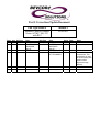
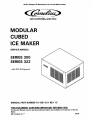
Quality Designers & Manufacturers for the Ice Maker Industry
IMI CORNELIUS INC.
MODULAR
CUBED
ICE MAKER
SERVICE MANUAL
SERIES 300
SERIES 322
with R22 Refrigerant
MANUAL PART NUMBER 16-1951-811 REV "B"
THIS DOCUMENT CONTAINS IMPORTANT INFORMATION
This Service Manual must be read and understood before the installation and operation of this Ice
Maker.
IMI Cornelius Inc.
04-94
TABLE OF CONTENTS
...........................................
SPECIFICATIONS FOR 300............................
SPECIFICATIONS FOR 322............................
UNPACKING................................................
INTRODUCTION
...................................................
DIAGRAM 1 ................................................
UNIT LOCATION ..........................................
UNIT SET-UP ...............................................
DIAGRAM 2 ................................................
POWER SUPPLY CONNECTIONS ....................
LEVELING
4
....................................... 10-14
SANITIZING AND CLEANING PROCEDURE ...... 15
DIAGRAM 8 ................................................
15
WATER TREATMENT....................................
15
WINTER STORAGE.......................................
15
CLEANING THE CONDENSER COIL .................16
4
TROUBLESHOOTING SOLID STATE BOARD
4
TROUBLESHOOTINGTHE SENSORS
1
2
3
4
4
5
5
........................... 5
DIAGRAM 3 ................................................
5
DRAIN ........................................................
6
DRAIN CONNECTIONS .................................
6
WATER LEVEL RESERVOIR ...........................
6
DIAGRAM 4 ................................................
6
STARTING THE UNIT ...................................
6
DIAGRAM 5 ................................................
7
MOUNTING ON DRINK DISPENSERS ............. 7
ELECTRICAL CIRCUIT ...................................
8
PLUMBING CONNECTIONS
.
................................................
ADJUSTMENT FOR ICE BRIDGE.....................
DIAGRAM 7 ................................................
DIAGRAM 6
.
9
9
...........9
ADJUSTMENT FOR HARVEST SWITCHES....... 9
CHECKOUT FOR HARVEST SWITCHES
i
8
WIRING DIAGRAM
..... 16
............... 16
DIAGRAM 9 ................................................
16
REPLACEMENT OF SENSORS ........................
16
REMOVAL OF SOLID STATE CONTROL .......... 16
REINSTALLATION OF SOLID STATE CONTROL 17
.................................................
PARTS LIST
ILLUSTRATION PARTS BREAKDOWN
18
.............19
JNTRODUCTION
We have strived t o produce a quality product. The design has been kept simple thus insuring
trouble-free operation.
This manual has been prepared t o assist servicemen and users with information concerning installation, construction and maintenance of the ice making equipment. The problems of the
serviceman and user have been given special attention in the development and engineering of
our ice makers.
If you encounter a problem which is not covered in this manual, please feel free t o write or call.
We will be happy t o assist you in any way we can.
When writing, please state the model and serial number of the machine.
Address all correspondence to:
IMI CORNELIUS INC.
A Product of IMI Cornelius Inc.
One Cornelius Place
Anoka, MN 55303-1592
Phone 800-554-3526
FAX 612-422-3232
PRINTED IN USA
1
I
300 SERIES
-b
1.00 -0
30.00
-
t
5.00
18.38
L
23.50
I
BOTTOM VIEW
A
B
BACK VIEW
C
D
WATER INLET
PUMP OUT DRAIN
ELECTRICAL CONNECTlON
CONDENSATE DRAIN
111141
ICE PRODUCTION CAPACITY (approximate)
.....................................................
..............................................
.................................
Net Weight
Shipping Weight
Compressor Horsepower..
Refrigerant
Electrical
Freeze Cycle Amps Draw
Time Delay Fuse Ratings (amps)
Minimum Circuit Ampacity (amps)
Power Supply (Single Phase)
Plumbing Connections
Inlet Water Supply
Bin Drain
Waste Water-(from water cooled models)
Pump Out Drain Connection
122 Ibs.
138 Ibs.
1/3
R-22 IC
......................................................
7 fi- &64
................................. .8.0
....................... .20.0
...................... 15.0
............................. 1 15V-60Hz
........................................... Max. Pressure 50 PSI 3/8" SAE MFL Ftg
........................................................ Through Bin
............3/8 in. SAE MFL Fitting
..............................
2
1/2 in. ID Tubing
SPECIFICATIONS
J--- -
322 SERIES
22.00
4-
5.00
1.00
23.50
21.00
2.25
A
NOTE:
BACK VIEW
A
B
C
BOTTOM VIEW
M U S T USE 20
AMP RECEPTACLE.
WATER INLET
PUMP OUT DRAIN
ELECTRICAL CONNECTION
i l l IA n
ICE PRODUCTION CAPACITY (approximate)
Model Number
(Condenser)
AC-322-SS-MH&DM
(Air Cooled)
Ambient
Temp F
Incoming
50°
243#
224#
70O
80O
Water Temp
70°
227#
209#
F
80°
21 6#
198#
17R#
900
.....................................................
..............................................
..................................
Net Weight
Shipping Weight
Compressor Horsepower.
Refrigerant......................................................
Electrical
Freeze Cycle Amps Draw
Time Delay Fuse Ratings (amps)
Minimum Circuit Ampacity (amps)
Power Supply (Single Phase)
Plumbing Connections
Inlet Water Supply
Bin Drain
Waste Water-(from water cooled models)
Pump Out Drain Connection
122 Ibs.
138 lbq.
1/3
R-22 f 6 ” j
&
.................................. 8.0
........................ 20.0
..................... .20.0
............................. 115V-60Hz; 230V-60Hz
...................................... .;.. . Max. Pressure 50 PSI 3/8“ SAE MFL Ftg
........................................................ Through Bin
............Two 3/8 in. SAE MFL Fitting
.............................. 1/2 in. ID Tubing
3
UNPACKINQ
UNIT LOCATION
1.
Uncrate machine and/or bin by removing the staples from around the
bottom of cardboard crate and lift
off.
2.
Remove bolts fastening the crate skid
t o the bottom of the unit. If auxiliary
legs have been purchased for the bin,
they should be installed at this time.
If legs are used, adjust the leveling
legs of the storage bin until the unit is
level and all four (4) legs are in solid
contact with the floor. Leveling is
very important t o obtain proper
draining and t o maintain the proper
level in the water pan of the ice cuber.
NOTE: If the bin is to be installed flush to
the fldor, the machine must be sealed to the
floor with an approved mastic such as Dow
R. T. V. #732, 734, or G.E. # 702, 108. This
is an N.S.F. requirement and is the
responsibility of the installer.
1
Allow at least a minimum of six (6)
inches at the rear and side of the ice
machine for proper air circulation.
2.
This unit has been designed t o be installed in an indoor location which is
clean and which can be adequately
ventilated.
The air and water
temperatures should never exceed
looo F or fall below 50° F.
(Temperatures above looo F will cut
the ice making capacity below an
economical level.
Temperatures
below 50° F will cause a malfunction
of thermostatic sensors).
3,
The unit should be located where air
circulation is not restricted. The unit
should not be located near a kitchen
grill. Air which contains grease vapors will deposit grease on the condenser. The condenser should always be kept clean.
UNIT SET-UP
Diagram 1
4
1.
Take off front panel of machine and
remove hardware bag and service
manual envelope.
2.
Mount the ice maker to the top of the
ice storage bin or adapter in the
proper position over the ice drop
opening. The ice maker must then be
sealed both on the outside and the
inside bottom edges with an approved N.S.F. mastic such as Dow
R.T.V. #732, 734, or G.E. R.T.V.
#102, 108. This is an N.S.F.
requirement and the responsibility of
the installer.
3.
Remove shipping tape from evaporator curtains.
MAKE PLUMBlNG CONNECTlONS
Water supply
diagram 3)
-
(Install per local codes)(See
The water inlet connection t o the unit is a
3/8" male flare connection located at the
rear of the ice machine.
WARNING: If the water pressure exceeds
50 pounds, a water pressure regulator
should be installed in the water inlet line
between the water shut-off valve and the
strainer.
ILL030
Install a reducer fitting on the shut-off valve
t o accommodate the water strainer, which is
supplied with each ice machine and MUST
be used. Install the water strainer with the
arrow in the proper direction of flow and
with the clean out plug down. This is very
important for cleaning. Connect either 3/8:
or 1/2" copper tubing between the water
inlet fitting of the ice machine and the water
strainer.
Diagram 2
MAKE ELECTRICAL POWER SUPPLY CONNECTIOW
Requirements: 115v/60hz 1 ph., 230v/60hz.
1 ph., or 220v 50ht. 1 ph when used.
REFER TO SERIAL PLATE FOR MINIMUM
CIRCUIT AMPACITY AND MAXIMUM TIME
DELAY FUSE SIZE.
For water cooled units, t w o water inlet connections are provided.
One for the ice
making (evaporator) section which is located
on the back of the machine and is a 3/8"
flared connection. The other is for the water cooled condenser.
ALL WIRING MUST CONFORM TO NATIONAL AND LOCAL ELECTRICAL CODES.
POWER CORD
/ (322
UNIT ONLY)
fJ9TE; TAKE CARE NOT TO
KINK OR COLLAPSE
VINYL TUBING.
RAINER WATER
ote Flow D i r e c t i o n )
SERVICE VALVES
50 PSI MAX.
\
WATER SUPPLY
ICE MAKING
WATER SUPPLY
WC CONDENSER
DUMP VALVE DRAIN
VENT
DRAIN WC
CONDENSER
DRAIN
CONDENSATION
+*--OPEN
BIN DRAIN
Diagram 3
5
TRAPPED OR
VENTED DRAIN
111018
The reason for the separate water inlet connections is that some installations use a
water tower for cooling the water used in
the water cooled condenser and some installations use treated water (filtered) for the ice
making inlet water connection. Be sure t o
install water line (incoming) t o the 3/8" male
flare connection on the back of the unit that
supplies water t o the water regulating valve
inside. The setting of the water regulating
valve from the factory should be 200
pounds for R-22 units. NOTE: Always flush
out water lines before starting unit.
Adjustments, if necessary, should be done
at installation.
WATER LEVEL RESERVOIR
The Float Valve is mounted in a fixed
position thru it's mounting bracket t o
maintain the proper water level in the water
reservoir. For the 300 & 322 series units
the bracket is mounted thru the bottom hole
the bracket.
~
SUPPORT,
Provide a suitable trapped open drain as
close as possible t o the area where the ice
maker is going t o be installed. This may be
an existing floor or a 1-1/4" trapped open
drain. T w o separate drain lines are required
for air cooled units, one for the storage bin
and one for the dump valve drain hose.
Diagram 4
WARNING: Ice maker will not operate properly when water supply temperature is below 50° F or above 100° F. Water supply
pressure must not exceed 50 PSI.
An additional separate drain line will be required for water cooled units from the outlet
of the condenser coil t o the drain. Run all
gravity drain lines with a good fall t o the
open drain.
STARTING THE UNIT
ALL PLUMBING MUST BE INSTALLED IN
ACCORDANCE WITH LOCAL CODES.
After the ice cuber has been unpacked and
leveled and all plumbing and electrical connections have been made, start the unit, and
check for proper operation.
NOTE: In some cases it may be necessary
to insulate the water supply line and drain
line. Condensate drbping to the floor can
cause serious staining of carpets or hardwoods.
A cuber has three separate circuits: the
water circuit, the refrigerant circuit and the
electrical circuit.
1.
DRAIN CONNECTION INSTALLATION INSTRUCTIONS
Taking care not t o kink or collapse vinyl
tubing at any point, route tubes t o any open,
trapped or vented floor drain. Run tubing to
drain separately. Do not tee any drain hoses
together. Add drain tubing required to reach
floor drain.
Start checking the water circuit by
making sure that there are not thread
or flare joint leaks, either outside the
unit or in the compressor section.
Next check the water flow over the
evaporator and make sure that all
holes in the water distributor are
open, (See Diagram 5) and that there
is no undue splash or loss of water
into the ice bin.
Also check to see if the float valve is functioning properly and the correct water level
is being maintained. Adjust if necessary.
6
L
4.
Remove evaporator curtain or cover.
5.
Install slide stop by inserting the rear
mounting screw thru the slide stop
into weld nut located on the lower
inner left wall and lightly tighten with
slide stop rotated upward.
6.
Install deflector by inserting the rear
mounting screw thru the deflector
into upper weld nut and lightly
tighten only with deflector rotated
upward.
7.
Loosen the bottom screws on both
the left and right side panels.
8.
Turn crate skid upside down and set
ice machine on the skid.
9.
Align the slots of the slide brackets
with the panel bottom mounting
screws and insert upward between
panel and frame.
10.
Securely tighten
mounting screws.
11.
Mount ice machine centered on top
of ice/drink dispenser.
12.
Rotate slide stop downward and
insert a mounting screw thru slide
stop into the weld nut and securely
tighten both mounting screws.
13.
Rotate deflector downward and insert
a mount screw thru the deflector and
into the weld nut and securely tighten
both mounting screws.
14.
Reinst a I I eva porat or/c urtain or cover
and the top of the ice machine.
15.
Reinstall ice machine front after
completion of installation and check
out.
16.
Carefully slide the ice machine to the
rear until movement stops.
IOLES
ILL025
Diagram 5
2.
3.
Check the refrigerant circuit by making sure that the condenser fan is
running. (This will be evident by air
noise.) Is the compressor running?
(Feel the casing for vibration.) Is the
evaporator getting cold?
Check bin-harvest switch operation.
(See procedure in manual).
INSTALLATION INSTRUCTIONS FOR
MOUNTING ON DRINK DISPENSERS
For mounting ice machine on t o an ice/drink
dispenser you should have the following
items:
2 Slide Brackets
1 Ice Deflector
4 Mounting Screws
1 Slide Stop
1 Top Front Cover (Plastic)
1 Backstop
1.
Uncrate ice machine by removing the
staples from around the cardboard
crate and lift off.
2.
Remove bolts fastening the crate skid
t o the bottom of the ice machine.
3.
Remove top and front of ice machine.
7
bottom
panel
temperature stays at or below this
temperature for appropriately 30 seconds
the control board will start the harvest
cycle.
The YELLOW L.E.D. will light, the
hot gas valve will open, fan motor will stop,
water dump solenoid will open and the
water
pump will
continue t o
run
approximately 10 seconds and allow all the
water in the evaporator t o be pumped down
the drain. The RED L.E.D. will flash until
the evaporator temperature rises above the
bridge thickness setting (one t o five flashes).
The hot gas valve and the water dump
solenoid will remain open until either the ice
slab falls and moves the evaporator curtain
away form the proximity switch or if
approximately five minutes elapses and the
control board automatically switches back
into the freeze cycle. When the evaporator
curtain opens and allows the proximity
switch t o work, the GREEN L.E.D. will light
and the YELLOW L.E.D. will go out
switching the unit from harvest t o the freeze
cycle. If the evaporator curtain is held open,
the GREEN L.E.D. will stay on and after
approximately 8 seconds have elapsed the
unit will shut down.
PLEASE NOTE: This opening will allow front
manual filling servicing of ice/drink dispenser
if more ice is needed in a given. period of
time.
17.
Pull the ice machine forward with
side handles t o normal position.
18.
Install black plastic top t o cover small
front opening between the ice
machine and icddrink dispenser.
CAUTION: Remember, when installing incoming water, electrical and drain lines, the
ice machine will slide back approximately 8
inches. Please compensate for this movement.
ELECTRICAL CIRCUIT SEQUENCE OF
OPERATION
Three colors of L.E.D. lights are mounted on
the control board t o indicate what is
happening in the operation of the unit.
The electrical sequence of operation seen
for a normal ice making cycle will be as
follows:
NO LIGHTS: Will indicate the unit is in the
freeze cycle (compressor, fan motor and
water pump "on"; hot gas valve and water
dump solenoid "off"). The control board will
delav the start of the water pump until the
evaporator temperature is pulled down t o a
pre-set point and allows the water pump to
start (can be, a several minute delay). The
control board will then lock the water pump
"on", no matter what temperature the
evaporator warms up to, when water starts
flowing over the evaporator.
if the
water curtain is opened the pump "lock" is
lost, the pump will stop and the evaporator
temperature will have t o pull down to the
pre-set point again. A second adjustable
evaporator temperature setting (Bridge
Thickness Setting) determines the length of
the freeze cycle.
I
\
\
OltI
\
m,
O0
\
\
\
3
LED
INDICATOR
LIGHTS
FLASHING RED L.E.D.: After the evaporator
temperature has pulled down low enough for
the correct amount of ice t o be on the
evaporator, the RED L.E.D. will begin t o
flash on and off.
If the evaporator
Diagram 6
8
ADJUSTM ENT FOR ICE BRIDGE THICKNESS
CHECKOUT PROCEDURE FOR HARVEST
BIN SWITCHES
An ice bridge connecting’ all cubes is necessary for a proper harvest of discharge of
cubes from the evaporator.
Turn on the ice machine and move the
evaporator curtain(s1 away from the evaporatorb). The ice machine should then shutoff in approximately 8 seconds. (See detail
A %t B).
To increase ice bridge thickness carefully
turn adjustment screw counter-clockwise QQ
mora than one turn at a time. Wait and
check thickness before re-adjusting. (See
Diagram 6 & 7)
Slowly let the evaporator curtain(s) move
back toward the evaporator(s) until the bottom edge of the curtain(s) is at least at the
bent edge of the water reservoir or closer to
the evaporator. With the curtain(s) at that
position, the machine should start. (See
detail C).
ADJUSTMENT PROCEDURE FOR HARVEST
BIN S WITCHES
If adjustment is necessary, loosen acorn
nuts and move proximity switch closer to
the curtain(s1 and make sure the curtain is
properly mounted. (See detail A).
Diagram 7
Re-check per above procedure.
DETAIL ’’ B”
I
I
e
e
THERMOWELL
PRoXIMITY
EVAPORATOR*+,
CURTAIN
-
EVAPORATOR
CURTAIN
DETAIL ” C ”
WATER
RESERVO
DETAIL ”A”
9
ILL02 1
C
I
I
I
I
I
, !
I
1
1
I
WH
L
FAN MOTOR
bnnl
BK
UJ.
BK
WATER
r
PUMP
ORI
OR
/
I
H-t-l
I
I
RD
...
115 VOLTS 60 HZ
NOTES:
The solid s t a t e control DELAYS t h e s t a r t of
the water pump until t h e evaporator
t e m p e r a t u r e reaches 2 0 F.
10
111172
I
'
m
la
rl.
I
la
yu
ad
1
FAN MOTOR
t
RD
4%
WATER
PUMP
I
WH
WH
HIGH PRESSURE CONTROL
-
- BR
SWITCH
OR
~
R
SOLENOID
HOT GAS
D
-
-
I
RD
-
I
J-OR'
-F+
1
WATER
DUMP
SWITCH
1Br
wH
I
BK
F@
WATER
DUMP
SOLENOID
WH
230 VOLTS 50 HZ
<ea>
IMI CORNBLIUI INC.
NOTES:
The solid s t a t e control DELAYS t h e s t a r t of
the water p u m p until t h e evaporator
t e m p e r a t u r e reaches 20' F.
11
ill173
q-i1D
COMPRESSOR
v
COMPRESSOR
OVERLOAD
POWER CORD
Fp;+DR-
WH
I
START
CAPACITOR
'
I
WH
BK
I
I
I
WH
FAN MOTOR
L
t
w1
I
OR1
OR
HOT GAS
SOLENOID
-F+
I
WATER
DUMP
SWITCH
BK
I
";
WATER
DUMP
SOLENOID
WH
115 VOLTS 60 HZ
NOTES:
The solid s t a t e control DELAYS t h e start of
t h e water pump until t h e evaporator
temperature reaches 20' F.
12
ill 174
1
1
?OMPRESSOR
OVERLOAD
COMPRESSOR
BL
BR
I
WH
1
I
I
I
I
OR/\
/\_
HIGH PRESSURE CONTROL
(W/C ONLY)
OR
L
HOT GAS
SOLENOID
WATER
DUMP
SWITCH
WH
2 0 8 l 2 3 0 VOLTS 60 H Z ,
IMI CORNILIUI INC.
/
/
NOTES:
The solid s t a t e control DELAYS t h e s t a r t of
t h e water pump until t h e evaporator
t e m p e r a t u r e reaches 20’ F,
13
111143
- BK
START
CAPACITOR
WH
WH
I
I
I
BK
I
WH
FAN MOTOR
L
1
RD
WATER
PUMP
HIGH
I
WATER
DUMP
SOLENOID
HOT CAS
SOLENOID
WATER
DUMP
SWITCH
WH
230 VOLTS 50 HZ
NOTES:
The solid s t a t e control DELAYS t h e s t a r t of
t h e water pump until t h e evaporator
temper,ature reaches 20' F.
14
J
ill175
drain away. Allow float valve t o fill
reservoir with clean, fresh water.
Circulate for approximately 1 minute.
Depress dump valve switch and allow
water to drain away. Repeat three
times.
SANITIZING AND CLEANING PROCEDURE
I
1.
Remove front panel t o gain access t o
the on-off-clean switch.
2.
Push switch to "clean" and allow the
ice on the evaporator to release or
melt away.
6.
Mix a sanitizing solution of 1/2 oz.
household bleach t o one gallon of
water. This mixture will provide 2 0 0
ppm chlorine. Using a non-metallic
bristle brush, scrub the following:
A.
Inside surface of the ice bin including
top and door.
6.
Inside surface of the ice maker to include evaporator section in the ice
machine including the top, front panel
and evaporator splash curtain.
C.
Make sure splash curtain is correctly
positioned.
7.
Depress dump valve switch and allow
cleaner to drain away. Allow float
valve to fill reservoir with clean, fresh
water. Circulate for approximately 1
minute. Depress dump valve switch
and allow water t o drain away. Repeat three times.
8.
Push switch from "clean" to "on"
position.
9.
Replace front panel.
DUMP
SWITCH /
ON/OFF/CLEAN
WATER
PUMP
3.
Remove ice from storage bin.
4.
If lime scale is present add 2 oz. of
'I Lime-A-Wa y " or
CaIgon Nic keISaf e
Ice Machine Cleaner" directly into
water reservoir.
Circulate for no
Depress
longer than 15 minutes.
dump valve switch on side of control
box and allow cleaner or sanitizer t o
drain away. Allow float valve t o fill
reservoir with clean, fresh water.
Circulate for approximately 1 minute.
Depress dump valve switch and allow
water t o drain away. Repeat three
times.
WATER TREATMENT
Depending on the water source for the ice
maker, water treatment may be necessary
to prevent calcium or lime scale deposits,
bad taste and odor, clorine problems, as well
as slime growth. If these conditions exist,
contact your Cornelius Distributor or Dealer
for information on water treatment systems
Cornelius offers.
CAUTION: All ice machine cleaner must be
flushed out of the system before the sanitizing solution is used in Step 5. The reaction
of the two chemicals can cause hazardous
gases to be generated.
5.
Pour 1/2 oz. of household bleach intO
the water reservoir and circulate for
15 minutes t o sanitize the circulating
water system including the evaporator, pump, distributor and all interconnecting vinyl tubing.
Depress
dump valve switch on side of control
box and allow cleaner or sanitizer to
15
rate thermometer. Ice water must be
WINTER STORAGE
32O F.
If the unit is t o be stored ‘in an area where
the temperature will drop below freezing, it
is most important that all water lines be
drained t o prevent them from freezing and
possible rupture.
7.
Insert the sensor into the ice water
and soak for a minimum of t w o minutes.
8.
With a zerod ohmmeter, measure the
resistance across the t w o wires of
the sensor lead. It should read 281 5
ohms
or -10% (281 ohms) on
units built before March 1994;
or 5% (140 ohms) on units built from
March on.
To blow out the waterline, disconnect the
water supply at the cabinet inlet and use air
pressure t o force the water into the water
reservoir pan. This can then be removed
from the water pan.
+
+
CLEANING THE AIR COOLED CONDENSER
NOTE: If the above ohm reading is not
within the range stated, the sensor is bad
and should be replaced.
COlL
In order t o produce at full capacity, the refrigeration condenser must be kept clean.
The frequency of cleaning will be determined
A good
by surrounding conditions.
maintenance plan calls for an inspection at
least every t w o months.
CAUTION:
Condenser cooling fins are
sharp. Use care when cleaning.
Clean the air condenser coil from the back
of the machine with a vacuum cleaner.
Remove all the accumulated dust, lint, and
dirt.
BATH
I
TROUBLESHOOTING THE SENSORS
1.
Turn off power t o machine.
2.
Remove the front panel and electrical
box cover of the machine.
3.
Diagram 9
RECONNECTION OF A
PLACEMENT SENSOR
BLESHOOTING
Cut the suspected sensor wire at
least six inches from the thermowell
in which it is located.
4.
Remove the sensor from the thermowell.
5.
Carefully separate the wires and strip
the insulation off the end.
6.
Pack a glass or container with ice
and add some water t o make an ice
water solution. Check the temperature of the ice water with an accu-
ILL058
16
GOOD
AFTER
OR RETROU-
1.
Carefully separate the wires of the
sensor leads coming from the solid
state control and strip the insulation
off the end of each wire.
2.
Reconnect the sensor leads and twist
the stripped ends tightly.
Secure
with the proper sized wire nuts.
3.
Tape all wire nut connections to insulate connections from each other.
I
supports. The circuit board will not
"pop off" until all supports have been
pinched closed and the board is then
holding them in that position.
REMOVAL OF SOLID STATE CONTROL
FROM M A CHlNE
CAUTION; The circuit board is fragile, han-
dle with care.
PEINSTALLATION OF SOLID STATE CON1.
Turn off power t o machine.
TROL
2.
Remove front panel.
1.
Align all holes in the circuit board
over the plastic stand-off supports.
3.
Remove electrical box front cover.
2.
4.
Disconnect the through wire plwg
connections from circuit board.
5.
Carefully lift any corner of the circuit
board while pinching closed the top
part of the plastic "stand-off 'I support with needle nose pliers. The circuit board has t o be gradually worked
up over all four of the "stand-off"
Carefully push downward at all hole
locations until board seats on all the
stand-off supports.
(Sometimes a
snap will be heard as this seating
takes place.)
3.
After the circuit board is seated,
carefully connect the wiring to the
circuit board.
17
Part # Corrections/Update Document
Unit Type/Model #
Modular Cubed Ice Maker
Series AC/WC 300, 322
with R22
Page Item Old Part
Desc.
18
12 165595000 FAN BLADE
18
37 42297
WATER DUMP
SOLENOID
VALVE
n/a
n/a
n/a
n/a
New Part
165595003
161456010
166074000
162964003
Manual #
161951811
Desc.
FAN BLADE
WATER DUMP
SOLENOID
VALVE
AIR FILTER KIT
COMPRESSOR
KIT TECUMSEH
Agent Date
Notes
JLS 01/30/03
JLS 01/30/03
JLS
JLS
01/30/03
01/30/03 Kit includes start
components. This
compressor is used
for units starting with
serial number
DCxxxx through
NExxxx.
PARTS LIST
ILL.
1
2
3
4
5
6
7
8
9
10
11
12
13
14
15
16
17
18
19
20
21
22
23
24
25
26
27
28
29
30
31
32
33
34
35
36
37
38
39
40
41
42
43
44
45
46
47
48
49
50
51
52
53
Control, Circuit Board
Switch, On-Off-Clean
Relay, compressor start
Relay, Power
Capacitor, compressor start
Relay
Drier
Valve, Crankcase pressure reg.
Valve, Shrader
Core, Shrader Valve
Cap, Shrader Valve
Compressor
Motor, Fan
Blade, Fan
Shroud
Condenser
NIA
Pump, Water
Valve, Thermo Expansion
NIA
Valve, Hot Gas
Tube, Water Pan to Pump Inlet
Cap, reservoir drain
Reservoir, Water
Float and Valve
Bracket, Float and Valve
NIA
Tee
NIA
Orifice, restrictor
Evaporator
End Cap
Distributor, water
Cover, evaporator
Bracket, front cover mount
Condenser coil, water cooled
Valve, water regulating
Bracket, back cover mount
Valve, water dump solenoid
Switch, harvest-bin proximity
Plug, dump valve
Plug, HGV
Cord Asy
Handles
NIA
Motor, compressor cooling
Blade, fan (water cooled)
NIA
Clip Spring
Filter
Control, high pressure (water cooled1
Kit, evaporator sensor
NIA
Splash guard
Switch, water dump valve
PART NO.
PART NO.
PART NO.
322-230V
asw37356
161 163001
164884004
43424
NIA
164883000
164876001
20654
21214
23988
162964003
16 1871003
165595000
16 1890002
161870002
NIA
4101 1
16192 1001
NIA
09214
165636001
4568 1
-4+wf
165681000
165692001
NIA
00987
NIA
22176
45500
42493
43056
45539
45536
01210
01211
38743
42297
45537
45880
45881
161085001
161525001
NIA
07470
09355
NIA
166037000
166038001
165677001
161456002
NIA
45541
45866
161163001
164884004
43424
NIA
164883000
164876001
20654
21214
23988
162964003
16187 1003
165595000
161890002
161870002
NIA
4101 1
161921001
NIA
09214
165636002
45681
407 13
45950
164883000
164876001
20654
21214
23988
162964008
NIA
NIA
N/A
NIA
NIA
39144
161921001
NIA
23082
165636001
45681
83+46" 6 3 ISrnm? 4444.8165681000
165681000
165692001
165692001
NIA
NIA
00987
00987
NIA
NIA
221 76
22176
45500
45500
42493
42493
43056
43056
45539
45539
45536
45536
01210
01210
0121 1
0121 1
38743
38743
42781
42297
45537
45537
45880
45880
45881
45881
16 1085003
NIA
161525001
NIA
NIA
NIA
166152002
07470
09355
09355
NIA
NIA
NIA
166037000
NIA
166038001
165677001
165677001
16 1456002
16 1456002
NIA
NIA
4554 1
45541
45866
45866
,btq$$),
p-4
'
;
.
18
I
ch
0
\
ch
n,
J
cs
I
l‘
co
i
b
Y
A
I
co
n,
to
A
A
19
ILL146