1
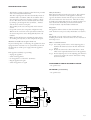
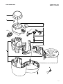
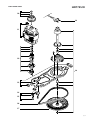
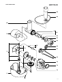
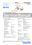
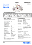
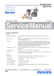
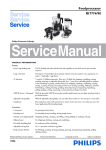
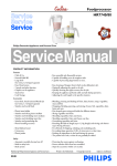
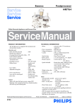
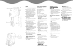
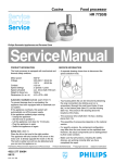
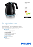
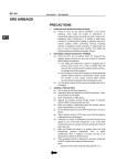
Essence
Food processor
HR7755/01
Philips Domestic Appliances and Personal Care
Service Manual
PRODUCT INFORMATION
TECHNICAL INFORMATION
- The Foodprocessor is equipped with mechanical and
thermal safety switches.
- Motor
Materials used:
- Bowl, bowl lid,
blender jar & safety cover
- Housing, screw cap, pushers,
inlay bowl handle, switch
- Emulsifying disc
- Feeding tray, sausage horn
- Kneading accessory
- Toolholder bowl, sausage seperator
- Insert holder
- Foodprocessor knife, insert discs
- Cutter, grinding discs
- Meat mincer processing tube,
worm shaft
-
: SAN
: PP
:
:
:
:
:
:
:
:
PP
ABS
PP / 30% chalk
POM
ABS
Stainless steel
Metal
Alu - alloy
Safety:
- Automatically resettable : protects motor against
thermal cut out
overheating
- Built – in safety lock
: detects wheter lid & bowl or
meat mincer are assembled
- Motor brake system
: stops the appliance wthin
1.5 seconds
- This product meets the requirements regarding
interference suppression on radio and TV.
- After the product has been repaired, it should function
properly and has to meet the safety requirements as
officially laid down at this moment.
Published by Philips Domestic Appliances and Personal Care
03/07
-
-
: universal, radio / TV interference
suppressed
Power consumption : 800 Watt max.
Voltage & frequency : 230 V, 50 Hz
Cordset
: 100 cm, double insulated with
moulded on plug
Speed setting
: 2 speeds + pulse
Bowl capacity
: 2.5 L dry ingredients, 1.7 L liquids
Blender capacity
: total jar capacity 2.0 L,
1,5 L effective
Meat mincer capacity : 1.3 kg meat per minute (pork)
Speeds unloaded
: blender drive shaft 19500 rpm (max)
accessories drive shaft 2150 rpm
(max at speed 2 + pulse)
accessories drive shaft 1700 rpm
(min at speed 1)
Weight in fancy box : 6.900 g
Dimensions
fancy box (l x w x h) : 395 mm x 380 mm x 395 mm
Colours
: White with Vapor Dusk accents,
clear transparant bowl & jar
Printed in the Netherlands
© Copyright reserved
Subject to modification
REPAIR INSTRUCTIONS
HR7755/01
- The blender coupling on the motor shaft has been provided
with a customary left-handed thread.
The drive coupling (item 10) can be detached by means of
a hammer and a screwdriver. Strike the screwdriver with a
short sharp blow and remove the drive coupling, or block
the acc. drive wheel (item 17) and thereby the rotor shaft,
by sticking a pin through the hole (5 mm dia. – marked
with an arrow) in the bottom plate.
- The assembly of the accessories depends on the national
version.
- For specific versions, the component configuration may
differ from the one shown on the exploded view. However,
the actual components can be distinguished by their code
numbers.
- Make sure that all functions, including the safety devices,
are working correctly after you have completed the repair.
Automatic resettable cut-out (part of item 11)
To prevent damage due to overheating, the appliance has been
equipped with an automatic cut-out system.This system will
automatically cut off the power supply when the appliance
overheats.
If the appliance suddenly stops running:
- Unplug the appliance
- Switch off the appliance
- Let the appliance cool down for 15 minutes
- Plug the appliance in again
- Switch the appliance on again
Safety lock (item 7)
Place the lid on the bowl in the right position. The appliance
will only function if the line on the appliance is directly
opposite the mark on the lid of the food processor bowl and
the same holds for the other accessoires. The built-in safety
lock will now be deblocked and you can turn the appliance on.
Note that if both the blender jar and the bowl have been
correctly mounted, only the blender will function.
Important:
The appliance will not function, when the blender coupling
(item 10) has not been protected by the blender cover (item 1).
Note:
The blender cover can only be removed, when the bowl
including the bowl lid or the meat mincer are not mounted on
the foodprocessor.
How to set the belt tension:
Step 1: Give 30 N pretension force on the adjusting plate to
minimise the distances between the belt and the belt
wheels
Step 2: Reduce the tension force from 30 N down to 10 N
which is the required belt drive force for the appliance.
Step 3: Fix the adjusting screw on the adjusting plate when the
tension force reaches the value of 10 N (after coming
down from 30 N!)
DISASSEMBLY- AND RE-ASSEMBLY ADVISE
- No specific issues
OPTIONAL (accessories)
- No specific issues
P
red
OFF
blue
1
F1
brown
D1
U
red
2
R2
brown
blue
MAINS
F2
black
R1
C1
white
S1
yellow Rotor
S2
yellow
Change-over switch
in braking position
2-7
PARTS LIST
Pos
Service code
1
2
3
4
6
HR7755/01
Description
Pos
Service code
Description
4203 065 63470
4203 065 63620
4203 065 63480
4203 065 60630
4203 065 63490
Blender cover
Screw cap
Top housing
Switch assy
Housing parts
47
4203 065 63690
48
49
55
4203 065 63660
4203 065 63680
4203 065 63650
Metal knife
(incl. protecting cover)
Emulsifing disc
Toolholder
Blender safety lid
7
8
10
11
12
4203 065 63580
4203 065 63510
4203 065 63570
4203 065 63930
4203 065 63590
Safety switch lever
PCB brake
Blender coupling
Motor assy - 230V
Motor coupling assy
56
57
70
71
72
4203 065 63640
4203 065 63630
4203 065 64160
4203 065 64170
4203 065 64180
Blender lid
Blender jar
Housing upper part
Housing lower part
Mounting plate
13
14
15
16
17
4203 065 63600
4203 065 63540
4203 065 60310
4203 065 60440
4203 065 63560
Mounting plate
Adjusting piece
Motor screw
Tooth belt
Belt wheel
73
74
75
76
77
4203 065 64220
4203 065 64240
4203 065 64230
4203 065 64190
4203 065 64210
Gear assy
O-ring
Release button
Coupling part
Drive gear
18
19
30
4203 065 63610
4203 065 63980
4203 065 63990
4203 065 64010
4203 065 64030
Single speed gear
Cordset EURO
Cordset UK
Cordset SWISS
Press cone
78
80
81
82
83
4203 065 64200
4203 065 64050
4203 065 64060
4203 065 64070
4203 065 64080
Sealing
Feeding tube
Worm shaft assy
Coupling
Cutting blade
31
32
33
34
35
4203 065 63870
4203 065 63800
4203 065 63760
4203 065 63770
4203 065 63780
Sieve
Pusher closed bowl
Bowl lid
Lid bearing
Closed bowl
84
85
86
87
88
4203 065 64090
4203 065 64100
4203 065 64110
4203 065 64140
4203 065 64150
Cutting disc (Dia. 4mm)
Cutting disc (Dia. 8mm)
Screw ring
Sausage horn bearing
Sausage horn
41
42
44
46
4203 065 61540
4203 065 61560
4203 065 61520
4203 065 63970
Insert slicing medium
Insert shredding medium
Insert holder
Plastic kneader
89
90
4203 065 64120
4203 065 64130
Feeding tray
Pusher
A
4203 065 63190
Wire connector for 2 wires
3-7
EXPLODED VIEW
HR7755/01
1
2
3
4
7
8
6
A
4-7
EXPLODED VIEW
HR7755/01
10
19
11
12
18
13
14
15
16
17
5-7
EXPLODED VIEW
HR7755/01
41
30
42
31
55
44
56
32
46
47
33
57
34
48
35
49
6-7
EXPLODED VIEW
HR7755/01
90
89
80
82
81
70
83
85
86
75
84
72
87
77
88
73
76
78
74
71
7-7