1
Service Manual
Document Scanner
SCAMAX
®
2600/4000
As at 04.06.2002 (SB)
SCAMAX®2600/4000
Tech. Manual 06/2002
T-1
Table of Contents
Technical Manual Part T
1
INTRODUCTION................................................................................................................................... 4
1.1
1.2
1.3
2
SYSTEM COMPONENTS..................................................................................................................... 8
2.1
2.2
2.3
3
SCANNER MODELS, OPTIONS AND ACCESSORIES .............................................................................. 4
TECHNICAL DATA ............................................................................................................................. 5
COMPLIANCE WITH REGULATIONS AND STANDARDS: .......................................................................... 6
SCAMAX 2600 WITH VIDEO INTERFACE ........................................................................................... 8
SCAMAX 2600 WITH SCSI INTERFACE ............................................................................................ 8
SCAMAX 2600 WITH GREYSCALE INTERFACE .................................................................................. 9
SCANNER COMPONENTS AND FUNCTIONS................................................................................. 11
3.1
CCD-LINEAR-CAMERA ................................................................................................................... 15
3.1.1
Camera types........................................................................................................................ 17
3.1.2
Camera Faults ...................................................................................................................... 18
3.1.2.1
3.1.2.2
3.1.2.3
3.1.2.4
3.1.2.5
3.1.2.6
Changing Camera Board Type 2+3 ................................................................................................. 18
Changing Camera Board Type 0 ..................................................................................................... 19
Changing the CCD Linear Sensor ................................................................................................... 19
Camera Adjustment for SCAMAX®2600 Type 3 ............................................................................. 21
Camera Adjustment for SCAMAX®2600 Type 0. ............................................................................ 24
Camera Adjustment for SCAMAX®4000 Type 2 ............................................................................. 25
3.2
CONTROLLER-BOARD REV. B ......................................................................................................... 26
3.3
EXCHANGING THE CONTROLLER BOARD .......................................................................................... 29
3.4
DTPLUS BOARD ............................................................................................................................. 30
3.5
I/O BOARD ..................................................................................................................................... 33
3.6
ULTRASOUND DOUBLE-FEED DETECTOR ......................................................................................... 35
3.7
FOOTSWITCH ................................................................................................................................. 36
3.8
ENDORSER .................................................................................................................................... 36
3.8.1
Printhead............................................................................................................................... 36
3.8.2
Photocell ............................................................................................................................... 37
3.8.3
Processor Board ................................................................................................................... 37
3.8.4
Endorser Settings ................................................................................................................. 39
3.8.4.1
3.8.4.2
3.8.4.3
3.8.4.4
3.8.4.5
3.8.4.6
3.8.4.7
3.8.4.8
3.8.4.9
Print Density for Text/Barcodes (Druckdichte/BcDichte%) .............................................................. 40
Character Distance (CharAbstand).................................................................................................. 41
Thickness for Text/Barcodes (Fettdruck/BcFettdruck) ..................................................................... 42
Barcode Lines Ratio (BcBalkenVerh.) ............................................................................................. 42
Endorser Counter (PagiNummerH/L)............................................................................................... 43
Time & Date (Zeit Datum) ................................................................................................................ 43
Print Position Time (KopfStbyZeit)................................................................................................... 43
Cleaning the Print Head (Kopfreinigung) ......................................................................................... 43
Print Head Voltage (InkHead Spng)................................................................................................. 44
3.8.5
Change Endorser Settings.................................................................................................... 44
3.9
POWER SUPPLY ............................................................................................................................. 47
3.9.1
Mains Power Switch Unit ...................................................................................................... 47
3.9.2
Mains Transformer................................................................................................................ 48
3.9.3
Switching Power Supply ....................................................................................................... 48
3.10
LAMP UNIT ................................................................................................................................. 50
3.10.1 Rectifier Board ...................................................................................................................... 50
3.10.2 Electronic Lamp Ballasts ...................................................................................................... 50
3.10.3 Fluorescent Lamps ............................................................................................................... 50
3.11
OPERATOR PANEL ...................................................................................................................... 51
3.12
OPTICAL COMPONENTS UNIT....................................................................................................... 53
3.13
PAPER TRANSPORT .................................................................................................................... 54
3.13.1 Input Hopper with Drive Motor .............................................................................................. 54
3.13.2 Diagnosing Paper Input Hopper Faults ................................................................................ 57
3.13.2.1 General Faults ................................................................................................................................. 57
SCAMAX®2600/4000
Tech. Manual 06/2002
T-2
3.13.2.2 Condition dependent Faults with GAL 2.2 ....................................................................................... 58
3.13.2.3 Condition dependent Faults with GAL 2.3 ....................................................................................... 59
3.13.3 Paper Feed with Separation System .................................................................................... 60
3.13.4 Rubber Roller Pairs (two) ..................................................................................................... 63
3.13.5 Paper Output Path ................................................................................................................ 63
3.13.6 Output Hopper ...................................................................................................................... 64
3.13.7 Drive Mechanism with Stepper Motor................................................................................... 65
3.14
DESCRIPTION OF SCAN ROUTINE FLOW ....................................................................................... 68
Spare Parts List Part E
Service Program Part S
SCAMAX®2600/4000
Tech. Manual 06/2002
T-3
1 INTRODUCTION
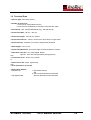
The SCAMAX 2600 is a bitonal document scanner. It is designed to be used in document conversion
projects of medium volume requiring medium speed. The scanner is driven from a PC connected to it.
This PC also receives the scanned images and processes them further as required.
The SCAMAX 4000 is a colour document scanner. It is identical in construction to the SCAMAX 2600 ,
except that it is equipped with a colour camera.
1.1 Scanner Models, Options and Accessories
The scanners are currently available in the following Models:
Description
SCAMAX 2600 Simplex Video, B/W with one scan unit for single sided
scanning and video interface
SCAMAX 2600 Duplex Video, B/W with two scan units for double sided
scanning and video interface
SCAMAX 2600 Simplex SCSI, B/W with one scan unit for single sided
scanning and SCSI interface
SCAMAX 2600 Duplex SCSI, B/W with two scan units for double sided
scanning and SCSI interface
SCAMAX 4000 Simplex Video, Colour with one scan unit for single sided
scanning and video interface
SCAMAX 2600 Duplex Video, Colour with two scan units for double sided
scanning and video interface
Options:
Greyscale interface (SCAMAX 2600 only)
8 Bit; 256 Greyscales
DTplus-Board
(SCAMAX 2600 only)
To scan difficult, low contrast documents
Endorser
Prints text, numbers or dates on backside of documents
Acid resistant paper rollers
For self-carbonising (impregnated) paper
Accessories:
Purpose built work desk
Optical Filter #60 green
(SCAMAX 2600 only)
Optical Filter #40 red/orange (SCAMAX 2600 only)
Optical Filter #90 red
(SCAMAX 2600 only)
Optical Filter #81 blue
(SCAMAX 2600 only)
Feeder extension for A3 documents
Foot Switch (Paper separation On/Off)
Anti-Static Brush for output hopper
SCSI-Cable (50 Pin) high density
SCSI-Cable (68 Pin) high density
White Calibration Paper (10 sheets)
Cleaning Kit
Vacuum Cleaner
SCAMAX®2600/4000
Tech. Manual 06/2002
Part Number
s2600010
s2600020
s2600030
s2600040
s4000010
s4000020
s0000055
s0000500/1
s2600200
s2500130
s0000055
s9000030
s9000021
s9000020
s9000010
s2500122
s9000100
s2500125
s9020100
s9020110
s9100000
s9100010
s9100020
T-4
1.2 Technical Data
- Scanner type: CCD array camera
- Number of scan units:
- 1 scan unit for single sided scanning
- 2 scan units for simultaneous scanning of front and back page
- Resolutions: 200, 240 (SCAMAX2600 only), 300 and 400 dpi
- Document widths: 26 mm - 320 mm
- Document lengths: from 60 mm upward
- Document thickness: various, can be set for each stack or single sheet
- Document feed: automatic from stack or single sheet hand feed
- Stack height: max. 50 mm
- Double Feed Detection: document length check and ultrasound sensor
- Video Port out to PC: V24, video digital, bitonal
optional: video with 256 greyscales (8 bit greyscale)
with
- Control Port to PC: serial, 9 pin, RS232
or:
- SCSI 2 Port to PC: 50 pin, high density
with
- serial interface to service PC
- Binarisation method:
- Standard unit
- with Dtplus board:
SCAMAX®2600/4000
1. with fixed threshold
and
2. with one-dimensional auto-threshold
with two-dimensional auto-threshold
Tech. Manual 06/2002
T-5
- Scan speed (at 200 dpi resolution):
- A4 portrait:
- 75 sheets per minute (simplex)
150 pages per minute (duplex)
- A4 landscape:
- 90 sheets per minute (simplex)
180 pages per minute (duplex)
- Electrical requirements:
230 V, 50 Hz, 1,0 A
115 V, 60 Hz, 2,0 A
- Dimensions (width, height, depth):
510 mm, 365 mm, 650 mm
- Weight: 39 kg
- Endorser: the optionally fitted endorser
facilitates printing of free-dorm text, date, time and sequence number
on the back of documents
- Environmental requirements:
- room temperature: 10° to 35°C.
- relative humidity: 30% to 80% without condensation
- Noise level: less than 70 dB
1.3 Compliance with Regulations and Standards:
The scanners Scanner SCAMAX 2600/4000 comply with the regulations and standards that form the
basis of the CE compliance declaration that follows:
SCAMAX®2600/4000
Tech. Manual 06/2002
T-6
SCAMAX®2600/4000
Tech. Manual 06/2002
T-7
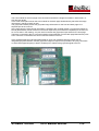
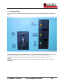
2 SYSTEM COMPONENTS
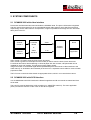
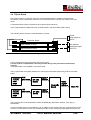
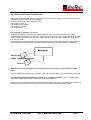
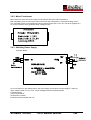
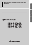
2.1 SCAMAX 2600 with video interface
Documents are illuminated and scanned inside the SCAMAX 2600. The picture information is digitised
and then sent to the external PC as an 8-bit parallel bitonal video signal for each side (front and back
respectively) via the video interface. Compression, image manipulation and storage 9in TIFF-G4 format
takes place in the PC.
Scanner S26/S40
Scanner
module 1
Scan PC
Controller
Board
Video
8 bit parallel
&
Scanner
module 2
Videointerface
Driver
Scanner
Interface
V 24
Application
Scan module 1 is used to scan the front of each document.
Scan module 2 (present in the duplex scanner model) is used to scan the back of each document.
For difficult documents, like handwriting or coloured paper with low contrast, a DTplus board can be
installed for each scan module. This enhances image quality greatly.
Image information is transmitted digital bitonal (black&white) from the scanner’s video interface to the
video board (f. ex. HISCAN or dunord board) in the scan PC. A separate control cable for communication
purposes is fitted.
The PC’s scan controls the video board via appropriate drivers, which in turn controls the scanner.
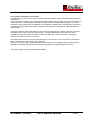
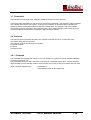
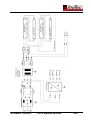
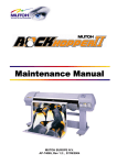
2.2 SCAMAX 2600 with SCSI interface
In a SCAMAX 2600 with SCSI interface the bitonal image data and all commands are transmitted via a
SCSI cable.
The scan PC must be fitted with a SCSI controller (f.ex. ADAPTEC 2940 AU). The scan application
(client) controls the scanner via the Twain or ISIS driver supplied.
SCAMAX®2600/4000
Tech. Manual 06/2002
T-8
Scanner S26/S40
Scan PC
TWAIN
or ISIS
Driver
Scanner
module 1
SMART
SCSI
Interface
SCSI
Controller
Scanner
module 2
Application
It is possible to control the SCAMAX 2600 via SCSI commands without using the Twain or ISIS driver.
Since the command set of the SCSI interface is by and large compatible with other manufacturers it is
relatively easy to generate a generic driver without great programming effort.
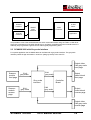
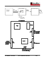
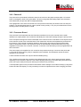
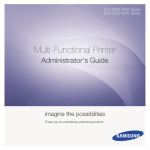
2.3 SCAMAX 2600 with Greyscale interface
For special application the SCAMAX 2600 can be fitted with a greyscale interface. The greyscale
interface passes image information in 8-bit form (256 grey levels) to the scan PC.
Output video
8 bit grey scale
front page
Scanner
module
front page
8 bit
grey scale
8 bit
grey scale
Controller
Board
Grey scale
interface
Scanner
module
reverse
page
8 bit
grey scale
Output
video bitonal
front page
8 bit
grey scale
Output
video bitonal
reverse page
Output video
8 bit grey scale
reverse page
SCAMAX®2600/4000
Tech. Manual 06/2002
T-9
The scan module for the front page of the document transmits the image information in 8-bit format, i.e.
with 256 grey levels.
In the case of a duplex scanner the scan module for the back page simultaneously transmits the image
information in 256 grey levels as well.
The greyscale interface passes the greyscale image information for the front and back page via a
separate port to the scan PC.
At the same time the same image information is passed to the controller board. It converts the images to
bitonal (black&white) format for the front and back respectively and transmits it separately to the scan PC.
As can be seen in the drawing, one port each for bitonal and greyscale output exists for the front page.
These are connected to the PC’s scanner interface (dunord-Board). For the back page identical twin ports
exist. These are connected to the second scanner interface in the PC.
If the SCAMAX 2600 has a DTplus-Board fitted for each scan module that board comes with an
integrated greyscale interface. Should greyscale images be required it is possible to fit a plug connection
on each board (special option) to lead to outside port to transmit the greyscale signal to the PC.
SCAMAX®2600/4000
Tech. Manual 06/2002
T-10
3 SCANNER COMPONENTS AND FUNCTIONS
The SCAMAX 2600/4000 scanner consists of the following main elements:
The paper transport system – it pulls sheets of paper into the scanner, transports them through the
machine and deposits them in the output hopper. It consists of input hopper, which is adjustable for single
sheet feed or stack feed, paper separation unit, transport mechanism and output hopper.
The illumination unit.
The optical system consisting of two mirrors plus a lens with colour filter.
The scan module 1, scanning the front of each document, is present in all SCAMAX scanners.
The scan module 2, scanning the back of each document, is only found in duplex models.
The controller board – controls all process in the machine.
The I/O board – converts TTL signals from the controller board into the signals required by the various
‚users’, such as motors. It also converts outputs from sensors, such as photocells and switches, into TTL
signals.
The operator panel – facilitates basic operation of the scanner, except for scan commands and internal
settings.
The power supply unit – supplies the necessary voltages for the entire machine.
The ultrasound double feed detector.
Optionally fitted elements are:
One DTplus board for each scan module, which significantly enhance images from difficult documents.
The greyscale interface.
The endorser - consisting of printer unit, endorser board and photocell. Used to print date, time, and so
on onto the back of each document during the scan process.
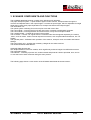
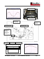
The following page shows a cross section of the SCAMAX 2600/4000 document scanner:
SCAMAX®2600/4000
Tech. Manual 06/2002
T-11
SCAMAX®2600/4000
Tech. Manual 06/2002
T-12
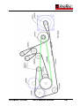
The principal of operation is as follows:
A single sheet or a stack of documents is placed in the input hopper. A photocell detects the presence of
document/s.
When the scan PC issues a scan command the machine pulls in the single sheet or top sheet of the stack
via the feed roller. The sheet travels through two guide plates till a rubber roller pair grips it. The sheet
reaches the scan area and is then grabbed by a second pair of rubber rollers. Subsequently, the sheet is
transport around a guide plate by yellow transport belts upwards and forward till it is deposited into the
output hopper.
In the scan area the sheet is illuminated by one or two fluorescent lamps, simplex or duplex. The lamps
are offset to each other to minimise ‚print-through’. The light reflected from each side of the sheet
contains the image information for the front and back respectively. Since the sheet is in continuous
motion each line is scanned in succession.
The reflected light hits a mirror that projects the light to a second mirror. The second mirror projects the
light to the lens, which sits in front of the CCD array.
The CCD converts the light containing the image information into an analogue electrical signal, which is
digitised and possibly binarised in the next processing step before being transferred to the PC.
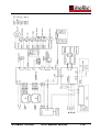
The following page shows an electrical block diagram:
SCAMAX®2600/4000
Tech. Manual 06/2002
T-13
SCAMAX®2600/4000
Tech. Manual 06/2002
T-14
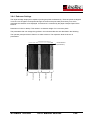
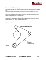
3.1 CCD-Linear-Camera
The CCD linear camera consists of a lens unit mounted on an aluminium plate and a CCD linear sensor
with associated electronics components fixed in a metal housing, which is attached to the aluminium
plate.
The document to be scanned is illuminated in the scan area. The CCD linear sensor captures the
reflected light containing the image information, after it has been refracted by two mirrors and passed
through the lens.
CCD stands for Charge Coupled Device. It is an electronic component containing capacitor elements
arranged in parallel. The capacitors convert the amount of light received into electrical current, the voltage
generated being proportional to the amount of light detected. An analogue-to-digital converter translates
the charge for each pixel into an 8-bit digital value.
This process takes place at very high speed, the clock speed being 20 MHz. This means that each
second an enormous amount of image information is read and output, i.e. 20 megapixels for bitonal and
60 megapixels for colour (20 for each channel red, green, blue).
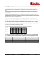
The CCD used has 5000 light sensitive pixel elements. This number is sufficient to scan an A4 page in
portrait mode (3,700 pixel) or an A3 in portrait mode (4,670 pixel) at an optical resolution of 400 dpi (dots
per inch).
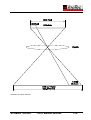
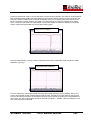
It is necessary to set the optical reduction in such a way that a width of 1 inch (25.4 mm) covers exactly
400 pixels on the CCD chip (see illustration next page).
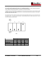
For lower resolutions the pixel elements shown in the table below are deactivated:
400 dpi
X
X
X
300 dpi
X
X
X
240 dpi
X
X
200 dpi
X
X
X
X
X
X
X
X
X
X
X
X
X
X
X
X
X
X
X
X
X
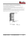
The scan speed (paper transport speed) is automatically adjusted according to the resolution selected.
200 dpi requires only half the number of lines, thus the paper can be transported at double the speed.
Resolution in dpi
200
240
300
400
SCAMAX 2600
Paper transport speed in m/min.
29,3
24,4
19,6
14,7
SCAMAX®2600/4000
SCAMAX 4000
Paper transport speed in m/min.
27,5
X
18,3
13,8
Tech. Manual 06/2002
T-15
Illustration of optical reduction
SCAMAX®2600/4000
Tech. Manual 06/2002
T-16
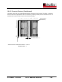
The reading of the CCD linear sensor and conversion into digital values described above takes place on
two channels. One channel each for odd and even pixels. With colour two channels are used for each
colour.
A shielded ribbon cable is connected to the CCD board (two for colour), which provides the connection to
the controller board and for colour also to the video interface.
Both mechanical and electronic adjustments are accomplished by using the service program.
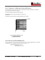
3.1.1 Camera types
Two different types of CCD linear cameras are used for the SCAMAX®2600/4000 scanners.
SCAMAX®2600:
B&W CCD linear camera Type 0
B&W CCD linear camera Type 3
SCAMAX®4000 :
Colour CCD linear camera Type 2
CCD linear camera Type 0
CCD linear camera Type 3
SCAMAX®2600/4000
CCD linear camera Type 2
Tech. Manual 06/2002
T-17
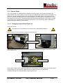
3.1.2 Camera Faults
The service program is used to determine whether a camera is faulty. The program can display the
camera status. If the camera status is shown as OK it is possible that the camera sends wrong data or no
data at all. This fact would be shown by an unexpected curve formation, heavy noise or absence of a
channel. If a problem is diagnosed it will not be immediately obvious whether it is caused by the camera
board and/or the CCD sensor. Therefore, several solutions present themselves. In the majority of cases
an exchange of the camera board will yield the result desired. This methodology has the advantage of
retaining the optical alignment of the camera.
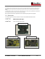
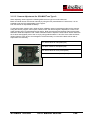
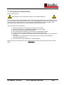
3.1.2.1 Changing Camera Board Type 2+3
Switch off Scanner!
All activities have to undertaken in accordance with current ESD regulations!
Remove the two screws of the EMV camera housing and lift lid.
Front
Back
Camera-EMV-Housing
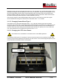
Pull the post connector from the board (1x for SCAMAX®2600 and 2x for SCAMAX®4000) and un-screw
the four plastic nuts.
Earth straps
Plastic nuts
Using a pair of pliers pull the board backwards out of the housing by the earth straps. Ensure the board is
pulled squarely out of the housing; otherwise the CCD sensor's contact pins will be bent.
Carefully insert the new board and fasten using the plastic nuts.
SCAMAX®2600/4000
Tech. Manual 06/2002
T-18
Replace the post connector and switch the scanner on. The next step is to set CCD sample delay, which
calculates and adjusts run time differences of the various components, using the service program. To set
the CCD sample delay insert a sheet of white calibration paper in portrait mode into the scanner and
transport it past the roller pair. Press the "D" key and follow the menu instructions. When finished insert
the sheet in landscape mode and perform a white calibration ("M" key).
If the service program's camera signal display does not show an improvement re-insert the original
camera board and exchange the CCD sensor as described under 1.1.2.3 instead.
3.1.2.2 Changing Camera Board Type 0
The difference to the procedure described under 1.1.2.1 is that the camera type 0 has two boards
mounted on top of each other. The board having the potentiometers is mounted on the CCD board, it can
simply be pulled off. The CCD board is fastened with four nuts (M3) and have to be unscrewed prior to
removal of the board. When fitting the new boards ensure that they sit squarely one on top of the other.
The camera signals are to be adjusted as described under 1.1.2.5.
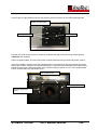
3.1.2.3 Changing the CCD Linear Sensor
All activities have to undertaken in accordance with current ESD regulations!
To change the CCD sensor it is necessary to remove the entire camera unit (consisting of: board. EMV
housing, board mounting plate and CCD sensor) from the scanner. Unscrew the fixing bolts (M4x10) and
remove the EMV housing with board mounting plate.
Front
Fixing bolts
Back
SCAMAX®2600/4000
Tech. Manual 06/2002
T-19
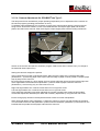
Unscrew the IC support plates and mark the position of the CCD sensor on the board mounting plate.
Board mounting plate
CCD sensor
IC support plates
Plug the new CCD sensor into the IC socket on the board and align to the previously marked position.
CAUTION! Check polarity.
Fasten IC support plates. The new CCD sensor must be absolutely free from dust and grease. Clean it.
Insert the complete camera unit into the adjustment frame, ensuring the springs are forward. Check that
springs are not bent. Compress the springs sufficiently to ensure the board mounting plate seats properly
behind the set-screws. Fasten fixing bolts, then undo them again a quarter of a turn. The camera should
now be movable within the adjustment frame.
Set-screws (A+B)
Set-screw ( C )
Camera adjustment
frame
SCAMAX®2600/4000
Tech. Manual 06/2002
T-20
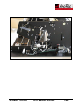
3.1.2.4 Camera Adjustment for SCAMAX®2600 Type 3
The lamps must have reached their proper operating temperature prior to adjustment of the camera via
the service program (operating period about 10 mins.).
To facilitate camera adjustment it is necessary to remove the output hopper plate by removing the two
fixing screws. Ensure the washers, which are located between the output hopper plate and the side
plates, don't fall into the scanner. After removing the output hopper plate close the folding mechanism.
Fixing screws
Switch on the scanner and start the ScanServ program. Select menu item 'Camera-Test'. (To change to
the backside camera press F10).
Setting the camera's straight line position
Insert a white sheet of paper in landscape mode. Sight across the edge of the camera's base plate
(illustration 2 + 3) to the top paper roller. Paper roller and edge of paper must be parallel. Transport paper
step-by-step into the scan slot.
By turning the set-screws (A + B) a quarter of turn at a time adjust the camera until the left and right side
of the signal deflect at the same time (illustration 1) when a sheet of paper enters the scan slot
(illustration 4). Avoid turning only one set-screw too much.
Right side signal leads: turn in left set-screw and/or turn out right set-screw.
Left side signal leads: turn out left set-screw and/or turn in right set-screw.
If the signal gets markedly worse when adjusting the camera (camera looks at edge of lamp holder)
reverse the adjustment and attempt to obtain the necessary adjustment by using the other set-screw.
Ensure enough play remains in the adjustment frame to allow for further manipulation.
When both side deflect evenly (illustration 1) adjust the camera in such a way that the edge of the paper
is in the middle of the scan slot (illustration 4) when maximum deflection (illustration 5) is reached. For the
backside the lamp holder and the paper rollers limit the scan slot.
SCAMAX®2600/4000
Tech. Manual 06/2002
T-21
Rear paper roller
Camera base plate
Illustration 2
Illustration 1
Point of view
To align Paper
Camera base plate
Point of view
Scan slot
Back side
Top paper roller
Point of view
Scan slot
Front side
Viewd through
drill holes
Paper
Illustration 3
Scan slot
Paper edge
Lamp holder
Illustration 4
SCAMAX®2600/4000
Tech. Manual 06/2002
Illustration 5
T-22
Centring is performed using an InoTec test sheet. The test sheet is placed in the scanner centred (without
play at the side paper guides). Drive the sheet into the scanner until the centre line on the sheet is in the
scan slot. Press F1 fifteen times to enlarge the display. Press F11 to display each pixel. Use the arrow
keys to scroll to the centre (auxiliary line 2522). Use set-screw (C) to centre the camera. Next, adjust
focus. Loosen the set-screw in the lens holder; turn the lens holder till maximum deflection is achieved.
Fasten camera and lens holder and check centre setting again.
Center & Focus setting
Set CCD sample delay ( „D“ key). When completed insert sheet in landscape mode and perform white
calibration ( „M“ key).
Completed white calibration
Focus is checked by scanning at 400dpi. All image processing options (cropping, deskew, filters, etc.)
have to be switched off and a fixed threshold must be used. Use the InoTec test sheet for this purpose.
Focus is OK when the direction of the DIN test symbols (screw heads) is at least 50% recognizable at a
value of 60. The grey scale's raster should be resolved in at least 5 – 8 fields. If these conditions are not
met, focus has to be re-adjusted.
SCAMAX®2600/4000
Tech. Manual 06/2002
T-23
3.1.2.5 Camera Adjustment for SCAMAX®2600 Type 0.
When adjusting camera type 0 the following differences to type 3 must be observed.
Black and white values must be set manually by using the four potentiometers. Furthermore, it is not
possible to set the CCD sample delay for the type 0.
The red channel is responsible for200 dpi.
To adjust the black values insert a sheet of black calibration paper in landscape mode into the scanner.
Using the service program, menu option 'Camera-Test', the camera signal is adjusted to a value of 20
(lower auxiliary line) via potentiometers P2 and P4. Both channels must be identical. Remove the black
calibration sheet and replace it with a white calibration sheet to adjust the white values. White values are
set to about 240 (highest point of the curve) by using potentiometers P1 and P3. Since white and black
values influence each other to some degree it will be necessary to re-check the black values and readjust them as necessary.
P1: White values for odd pixels (red)
P2: Black values for odd pixels (red)
P3: White values for even pixels (black)
P4: Black values for even pixels (black)
SCAMAX®2600/4000
Tech. Manual 06/2002
T-24
3.1.2.6 Camera Adjustment for SCAMAX®4000 Type 2
This section only covers the differences applicable to the camera adjustment for the SCAMAX®4000t.
To set the straight line position one has to change to the green channel ("G" key), since that is the one
which is red in the centre of the scan slot. (sequence: blue, green, red) The reason is that the Colour
CCD sensor is made up of three separate CCD sensors, one for each colour, which are physically apart
from each other.
Lamp holder
Red
Green
Blue
Paper
Centring is performed using an InoTec test sheet. Scanning has to done at 400dpi (IMPORTANT: switch
off cropping and deskew). View the resulting image using an image viewer. If the image shows a black
border on one side the camera has to be adjusted via the set-screw (C). This process has to be repeated
until the test sheet image is perfectly centred in the image viewer. When centred fasten the camera. Recheck centring after fastening.
Setting the CCD sample delay is only possible from ScanServ Version 1.4 and Firmware 3.25 EC.
Focus is checked by scanning at 400dpi, using the InoTec test sheet. Focus is OK when the direction of
the DIN test symbols (screw heads) is at least 50% recognizable at a value of 60.
To finish another white calibration has to be performed, which takes a while for the SCAMAX®4000
(approx. 7-8 mins per side).
SCAMAX®2600/4000
Tech. Manual 06/2002
T-25
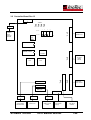
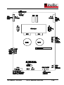
3.2 Controller-Board Rev. B
X6 16 pin
4 LED´s
D4
3 pin
D3
D2 D1
1
9600 Baud
Control
cable to
transparency
module
Clock
3
4
X1
34
pin
on
19200 Baud
DIL-Switch
11
MH
EPROM 3.XX EX
2
to I/O-board
position PL1
Clock
40 MHz
LCA
LCA
X4
34
pin
X7 10 pin
X2
34
pin
PC interface
or SCSIBoard
bitonal
X3
34
pin
Shielded
cable from
front camera
X8 10 pin
X9 10 pin
X5 4 pin
3 pin
Colour
control cable
dunord board
9 pin
Output control
cable to PC
SCAMAX®2600/4000
10 pin
Output control
cable to SCSI
board
Power input
from power
supply
Tech. Manual 06/2002
Shielded cable
from back
camera
T-26
The controller board manages all functions of the SCAMAX 2600/4000.
The scanner communicates with the scan PC via a serial interface (RS232), which controls the cameras,
motors, Dtplus boards and the endorser, according to commands received.
In addition, with the SCAMAX2600, image data from the cameras are processed for video interface (8 Bit
parallel). Binarisation, when using fixed threshold or one-dimensional automatic threshold, is executed in
the LCA’s of the controller as well.
DIL-Switches are used to set the baud rate and select the appropriate scanner type. As can be seen from
the diagram switch 1 is used to set the baud rate. It should always be set to 19200. Switches 2 to 4 are to
be set according to the table below.
9600
Baud
1
2
3
4
19200
Baud
ON
9600 Baud
19200 Baud
SCAMAX 5000
SCAMAX 2500
SCAMAX 4000
SCAMAX 2600
DIL Switch
1
2
Off
On
Off
On
Off
On
SCAMAX®2600/4000
3
4
Off
Off
On
On
Off
Off
Off
Off
Tech. Manual 06/2002
T-27
An EPROM of the type 27C512 is used to store the firmware for the SCAMAX 2600/4000. The firmware
can be exchanged or updated by changing the EPROM. Firmware is downward compatible, which means
newer firmware will be fully functional with older hardware versions.
The EPROM label shows the firmware version as well as the camera and controller type.
Example:
Version
Release
Identifier
3.2.1 E B
Camera type:
A – B&W 2 boards
E – B&W 2 boards
B – B&W 1 board
C - Colour
Controller type: A - LCA-Type A
E - LCA-Type E
(Type A is only found in older SCAMAX 2500 or 5000)
An EEPROM stores parameter values by busing the service program. As well, it stores the corrections
values after a white calibration has been executed for both scanner modules.
The RS232 (10-strand ribbon cable) of the external interface to the PC, is connected to X8 as shown.
In case of a SCSI scanner, the cable from the SCSI board is connected to X9.
X7 is only used in the SCAMAX 4000 and older SCAMAX 5000 scanners.
SCAMAX®2600/4000
Tech. Manual 06/2002
T-28
3.3 Exchanging the Controller Board
Switch off the Scanner!
All activities are to be conducted according to current ESD regulations!
Prior to exchanging the controller board the scan counter has to be read using the service program (menu
item: STATUS). As well, the parameter file (menu item PARAMETERS) has to be saved. The value of the
scan counter has to be written down. If communication is impossible due to a faulty controller, these
parameters can be obtained from InoTec by quoting the scanner’s serial number.
Action necessary for the changeover:
1.)
2.)
3.)
4.)
5.)
6.)
Remove the left hand cover and the cover plate of the controller
Remove all cables and the EPROM (FIRMWARE) from the controller
Remove the four M4 nuts and change the board
DIL-Switch to be set according to old controller. Re-fit EPROM and cables
Note scan counter of new controller and, if at hand, load parameter file
If parameter is not available, load default values and set values according to the values given
by InoTec
7.) For scanners of the type 2600 the sample delay has to be set and a white calibration
performed (see point 3.2.1.4)
8.) For scanners of the type 4000 perform a white calibration
Return the faulty controller board to InoTec together with the scanner’s serial number and scan counter
values.
.
SCAMAX®2600/4000
Tech. Manual 06/2002
T-29
3.4 DTplus Board
The DTplus board is an optional accessory for the SCAMAX 2600. It enables two-dimensional
binarisation, which is particularly useful for low contrast documents or those with certain colour hue
mixes.
A separate DTplus board is required for each camera (front and back).
The DT plus boards are fitted below the controller board in the same EMC metal housing.
The following sketch shows the cable distribution in detail:
bitonal
video output to
the PC
X3
X4
Controller board
X2
Dtplus board for front
Dtplus board for back
two optional
grayscale output
to the PC
Controller housing
A fan evacuates the heat generated by the DTplus board.
The fan must be checked and if necessary cleaned during each preventative maintenance
session!
If a DTplus board is not installed no fan will be fitted.
The DT plus board sits logically between the camera (front and back respectively) and the controller
board:
The actual function of this binarisation method is additionally described in detail in „From grey to
black&white“.
Another available option is the possibility to fit, in addition to the bitonal video port, a greyscale port to the
scan PC on each DTplus board. This is relatively simple since the 8-bit greyscale signal received by the
SCAMAX®2600/4000
Tech. Manual 06/2002
T-30
camera can easily be led to the scan PC. To achieve this, the 40-pin plug on the DTplus board is
connected to the scan PC.
For EMV technical reasons these plugs are only fitted if this feature is actually being used.
SCAMAX®2600/4000
Tech. Manual 06/2002
T-31
Controller Board
DT plus Board
Scanner
module
8 bit
grey scale
VST
Video
bitonal
Video
bitonal
to
Scan PC
8 bit
grey scale
to Scan PC
SCAMAX®2600/4000
Tech. Manual 06/2002
T-32
3.5 I/O Board
The I/O board converts the TTL signals from the controller board to signals required by the various
'users', such as motors and so on. Conversely, it converts output from sensors, photocells and switches
into TTL signals.
This board controls the following components:
the paper transport stepper motor
the stepper motor that sets the paper thickness
the DC elevator motor for the input hopper plate
the solenoid clutch.
the photocell that senses paper in the input hopper
the photocell fork next to the initial feed roller
the ultrasound double feed detector
The following four microswitches (found on the left hand side of the machine) are connected to the I/O
board:
two microswitches controlling the positioning of the input hopper plate for single sheet feed; one at the
top, the other at the bottom
one microswitch that signals the reference position of the paper thickness setting
and one microswitch that switches off the entire paper transport (motor, etc) when the output hopper is
lifted upwards. This is a safety measure to prevent injury.
The operator panel switches are connected to the I/O board via a ribbon cable. The board also has an
interface for the endorser.
Power supplied is 24V~ from the power supply transformer. The current is rectified on the I/O board to
output +16V to the DC motor for the input hopper plate and +12V to the endorser, as well as about +38V
to the stepper motors and clutch.
SCAMAX®2600/4000
Tech. Manual 06/2002
T-33
SCAMAX®2600/4000
Tech. Manual 06/2002
T-34
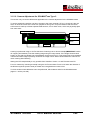
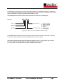
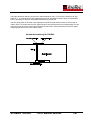
3.6 Ultrasound Double-feed Detector
The ultrasound double-feed detector recognizes two or more sheets of paper being fed simultaneously. It
stops the scanner or issues an error message.
It is located to the left of the initial feed rollers.
The system consists of:
one ultrasound transmitter
one ultrasound receiver
one control board
The principle of operation is as follows:
As the paper is pulled into the scanner it passes between the ultrasound transmitter and receiver.
The transmitter and receiver are aligned on a level that forms an angle of 60° to the paper level. The gap
between transmitter and receiver is 40 mm. Paper passes trough the unit at a distance of about 7 mm
from the transmitter.
The ultrasound transmitter generates ultrasound waves (>20 kHz) that travel through the paper and are
received by the ultrasound sensor. The control board measures the resulting reduction in amplitude.
Empfänger
Papier
Sender
IMPORTANT: it is the recognition of air-paper divisions that matters, not the thickness of the
paper!
An error message is displayed on the monitor of the scan PC depending on the user software employed.
The ultrasound double-feed detector is active when the paper separation is on. Turning the paper
separation off also deactivates the ultrasound double-feed detection.
A push button is located at the left of the SCAMAX 2600/4000 feeder front panel. Ultrasound double-feed
detection is turned off as long as this button is pushed yet paper separation remains active.
SCAMAX®2600/4000
Tech. Manual 06/2002
T-35
3.7 Footswitch
The footswitch is used when thick, stapled or folded documents are to be scanned.
Turning the paper separation on and off can be done with the footswitch. The footswitch cable is plugged
into a socket at the back of the scanner. As long as the footswitch is depressed paper separation is
turned off and the ultrasound double-feed detector is deactivated. The separator rollers are lowered
(move away from the red bands of the initial feed roller), which allows passage of documents up to the
maximum paper thickness without changing the paper thickness selector.
3.8 Endorser
The endorser prints information like date, time, sequence number and so on, on the back of the
documents during the scan process.
The endorser unit has the following components:
Printhead complete
Photocell
Processor board
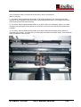
3.8.1 Printhead
The printhead is located beneath the top cover. It is mounted on a guide rod, which facilitates sideways
movement of the print unit.
The printhead and the processor board are connected via a 28-strand ribbon cable. A motor drives the
inkjet cartridge from the standby position, where the jets are covered, to the print position and vice versa.
Inkjet cartridges supported are:
SCAMAX®2600/4000
CANON BC 01
PELIKAN Easy Click for BJ-10e/BJ-200
Tech. Manual 06/2002
T-36
3.8.2 Photocell
The photocell is a photoelectric reflection sensor that is built into the paper transport path. It is housed
within a rectangular cutout in the guide plate. The senor recognises the leading edge of the document
and initiates the print process after an appropriate delay.
The engagement of the clutch at the start of a scan process causes the print head to drive into the print
position. If no printing takes place for a given period of time (usually 1 min.) the print head drives into the
standby position and the jets are covered.
3.8.3 Processor Board
The processor board translates the text information transferred to it by the controller via the serial
interface into a pixel pattern and controls the individual jets of the inkjet cartridge during the print process.
Once the specific settings have been transmitted to the endorser and it is activated it works asynchronous
to the scanner control of the controller board. This means each document that passes the photocell will
be printed on. This principle of operation applies to both regular documents as well as double feeds
and/or oversized documents. The sequence number is automatically increased after each print cycle,
regardless of the status of the scanner controller. A real-time clock with battery back up supplies date and
time information.
The power supply unit supplies the +5V current for the processor and logic. Current for the print head
(+12V) and for the jet control (+38V) is supplied by the I/O-Board. This board also carries the serial
interface to the controller.
A LED indicates the status of the photo cell that initiates printing.
The controller ensures that the processor board adjusts printing to the various paper transport speeds
depending on the resolution selected. This means adjusting the timing of the print delay (travel time from
photo cell to print head) and the print density (time between two pixel lines).
A small operator panel on the processor board allows certain settings to be made manually by using three
buttons and the LED display. It is only necessary to make an adjustment here when changing print fonts.
SCAMAX®2600/4000
Tech. Manual 06/2002
T-37
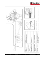
The following picture shows the endorser processor board:
Flash-Plug
Plug
Photocell
RS 232 (TTL)
to Controller
LED Indicator
Photocell
+5V
GND
+38V
+12V
Printhead
GND
RS 232
for PDIAG
Main Plug
(optional)
Parameters can be changed by using the PDIAG program. To achieve this the PC's COM1 or COM2 port
is connected to the processor board's RS232 port and the PDIAG program started. Remove the 10-pin
plug of the ribbon cable from the controller. To restore all settings to the original factory settings load the
file INOTEC.EEP by pressing F5. Subsequently pressing F2 transferres these values to the endorser.
Caution: Only change the parameters described below!!!
SCAMAX®2600/4000
Tech. Manual 06/2002
T-38
3.8.4 Endorser Settings
The inkjet cartridge employed is capable of printing 64 pixels simultaneously. These 64 pixels are aligned
in one line. As the paper is transported through the scanner the print head prints line by line, which
generates the character to be displayed. Line advance is controlled by the paper transport speed of the
scanner.
Resolution of a line is 360 dpi. This results in a character height of 4.5 mm at 64 pixels.
The parameters that can change the typeface in the horizontal direction are described in the following.
1
2
3
4
5
6
7
8
9
10
12
13
14
15
16
17
18
19
20
21
22
23
24
The operator prompts will be in German on older scanners. The respective texts are shown in
parenthesis.
1
2
3
4
5
6
7
8
9
10
11
12
Horizontal Pixel
(Printdirection)
...
SCAMAX®2600/4000
Char. Distance
Character2
Char. Distance
Character 1
Pixel Line
63
64
Tech. Manual 06/2002
T-39
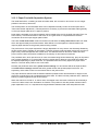
3.8.4.1 Print Density for Text/Barcodes (Druckdichte/BcDichte%)
The print density determines the distance between two pixel lines. However, this distance is also
influenced by the paper transport speed of the scanner.
To ensure that the print image is always the same regardless of paper transport speed (various
resolutions) the controller sets the print density according to the resolution selected. Changing this value
is only possible on a temporary basis.
Print density for barcodes, however, can be set as a percentage of text density. At 150% the bars and
spaces are half as wide again as at 100%. Naturally the distance between pixel lines increases as well.
1
2
3
4
5
6
7
8
9
10
11
12
6
5
4
3
2
1
Caution: Settings below 100% have no effect at a scan resolution of 200 dpi.
Horizontal Pixel
(Printdirection)
...
Pixel Line
63
64
Distance between two
Pixel Lines
(Density)
Default value barcode:
value text:
SCAMAX®2600/4000
100%
set by controller
Tech. Manual 06/2002
T-40
3.8.4.2 Character Distance (CharAbstand)
14
13
12
11
10
9
8
7
6
5
4
3
2
1
A character string with very small spaces between characters is hard to read. Therefore, a character
distance has been implemented, which is achieved by inserting 'blank pixel lines'. Blank lines can be
inserted within certain limits to improve the character display.
1
2
3
4
5
6
7
8
9
10
11
12
Hozizontal Pixel
(Printdirection)
...
63
64
Pixel Line
Character Distance = 2
Value limits for character distance: 01 to 10
Default value: 3
SCAMAX®2600/4000
Tech. Manual 06/2002
T-41
3.8.4.3 Thickness for Text/Barcodes (Fettdruck/BcFettdruck)
The last possibility to influence the print image is the parameter Thickness (Print Bold). The thickness
value sets the number of 'pixel line repeats'.
Increasing this parameter setting causes a fatter print.
The minimum number of pixel lines printed for a vertical line is:
Thickness x 2
1
2
3
4
5
6
7
8
9
10
11
12
12
11
10
9
8
7
6
5
4
3
2
1
Thickness for text and barcodes is handled separately by the endorser.
Horizontal Pixel
(Printdirection)
...
Pixel Line
63
64
Thickness = 2
Value limits for print bold: 01 to 05
Default value text: 1
Default value barcode: 2
3.8.4.4 Barcode Lines Ratio (BcBalkenVerh.)
Sets the relationship of narrow and wide barcode lines as well as the spaces between them. For example
if a relationship of 1:3 is desired the value has to be set to 6 (2:6 = 1:3).
Value limits barcode lines: 3 to 8
Default value: 5 (1 : 2.5)
SCAMAX®2600/4000
Tech. Manual 06/2002
T-42
3.8.4.5 Endorser Counter (PagiNummerH/L)
The endorser has an integral eight-position counter that is automatically incremented after each print
cycle. The counter contents can be part of the character string printed on each document. When the
counter reaches 99999999 it is automatically reset to 00000000.
Normally the counter is set by the scan software or the SCSI driver, but it can also be set via the menu.
3.8.4.6 Time & Date (Zeit Datum)
The endorser is fitted with a real time clock. The current time and/or date can be part of the character
string to be printed. Normally the real time clock is synchronised to the PC's system time by the scan
software. But it can also be set via the menu.
3.8.4.7 Print Position Time (KopfStbyZeit)
If the print head is in the print position and no printing takes place within the time set (in secs.) it is
automatically returned to the standby position to prevent drying out of the jets.
If the value is set to zero no automatic return to the standby position takes place.
Value limits for print position time: 0 to 9999[s]
Default value: 60[s]
3.8.4.8 Cleaning the Print Head (Kopfreinigung)
After prolonged use of an inkjet cartridge it is possible that individual jets appear to 'fade'. To correct that
condition the endorser has an inbuilt function 'clean print head'. This process addresses all available jets,
which usually removes minor soiling and clogging.
This function is also initiated every time the scanner is turned on.
CAUTION:
Execution of this function causes a lot of ink to be ejected from the cartridge.
SCAMAX®2600/4000
Tech. Manual 06/2002
T-43
3.8.4.9 Print Head Voltage (InkHead Spng)
Different voltages can power the inkjet cartridge jets. Increasing print head voltage causes more ink to be
ejected during the print process.
Value
0
1
2
Default 3
Jet Voltage
24.8V
25.2V
27.0V
28.0V
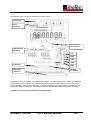
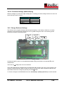
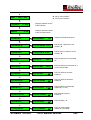
3.8.5 Change Endorser Settings
The endorser has a single line display with background lighting. It can display a maximum of sixteen
characters. Using the three push buttons the user is guided through the menu. The following picture
shows the functions of the three buttons.
Scroll Ð
or
Edit Ò
Scroll Ï
or
Cursor Î
Enter ª
Scrolling through the menu is accomplished downwards Ð by the left button and upwards Ï by the
middle button.
The Enter key ª displays the menu item selected.
If the value displayed can be edited use the middle button Î to position the cursor on the position to be
changed. Use the left button Ò to increase the value by one per push. When all positions desired have
been edited confirm the changes by pressing the Enter ª button.
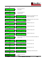
To save the changes to the EEPROM menu item <SaveSetup> (<SetUp speichern>) must be selected.
SCAMAX®2600/4000
Tech. Manual 06/2002
T-44
Ï
*S –set by scan software.
*C –set by the Controller.
PAGI – INK /900
Ï
Ð
ProgVers
Displays software version
of the Endorser.
x.xxx
Ï
Ð
HWVers
Displays hardware version
of the processor board.
x.xx
Ï
Ð
TextNumber
ª TextNumber
08
Displays the default string set.
Ï
Ð
CounterHigh
ª CounterHigh 0000
Edit the top 4 positions of the
counter. *S
ª CounterLow 0000
Edit the lower 4 positions of the
counter. *S
ª Density
2400
Edit print density for text printing.
*C
ª DensityBC
0100
Edit print density for barcodes in %
of text. Default: 100
ª Thickness
01
Edit print bold for print text.
Default: 1
ª ThicknessBC
02
Edit print bold for barcodes.
Default: 2
Ï
Ð
CounterLow
Ï
Ð
Density
Ï
Ð
DensityBc
Ï
Ð
Thickness
Ï
Ð
ThicknessBC
Ï
Ð
BcBarRatio
ª BcBarRatio
2:05
Edit barcode line relationship.
Default: 5 (1 to 2,5)
Ï
Ð
CharDistance
ª CharDistance
03
Edit character spacing.
Default: 3
ª PrintDelay
00
Edit print delay. *C
ª VoltageHead
03
Edit print head voltage.
Default: 3 (see table)
Ï
Ð
PrintDelay
Ï
Ð
VoltageHead
SCAMAX®2600/4000
Tech. Manual 06/2002
T-45
Ï
Ð
PrintPos
ª
Drives print head into
print position.
ª
Drives print head into
standby position.
Ï
Ð
StandbyPos
Ï
Ð
PrtPosTime
ª PrtPosTime
0060
Edit time print head stays in print
position. Default: 60 s
Ï
Ð
MoveTime
ª MoveTime
99
Displays time set in ms for moving
print head.
Ï
Ð
Config1
ª Config1 11000000
Displays config. byte 1
ª Config2 00000000
Displays config. byte 2
ª Config3 00000000
Displays config. byte 3
ª Config4 00000000
Displays config. byte 4
Ï
Ð
Config2
Ï
Ð
Config3
Ï
Ð
Config4
Ï
Ð
SaveSetup
ª
Saves all data changed via the menu to the EEP and initiates an
endorser reset.
Ï
Ð
Time (HHMM)
ª Time (HHMM) 0000
Edit current time *S
ª Date (DDMM) 0000
Edit current date *S
ª Year (YYYY) 0000
Edit current year *S
ª Inputs: 00000000
Displays logic state of all inputs.
Ï
Ð
Date (DDMM)
Ï
Ð
Year (YYYY)
Ï
Ð
InputsView
Ï
Ð
CleanHead
ª
SCAMAX®2600/4000
Initiates head cleaning
routine.
Tech. Manual 06/2002
T-46
Ï
Ð
ProcessorReset
ª
Initiates endorser reset.
ª
Initiates test print. (insert
paper under endorser!)
Ï
Ð
TestPrint
Ï
Ð
Date :
DD.MM.YY
ª Date :
01.01.00
Displays current date.
ª Time :
13.19:24
Displays current time.
Ï
Ð
Time :
HH.MM:SS
Ð
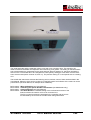
3.9 Power Supply
3.9.1 Mains Power Switch Unit
The mains power switch unit contains:
A ceramic housing with two fuses T 3.15A/250V, ∅5X20mm, suitable for both 230V and 115V mains
voltage. The ceramic housing has several electrical contacts and can be inserted in two positions. Each
position displays either 230V or 115V.
The ceramic housing can be removed by using a screwdriver.
a LC system filter
a mains switch
a connection for the power cord
an elastic plastic covering that guards against touching live parts. This is particularly important when
adjusting the back camera.
Changing mains voltage prior to first time use and changing fuses is described in the operating
instructions.
SCAMAX®2600/4000
Tech. Manual 06/2002
T-47
3.9.2 Mains Transformer
Mains power for the mains power supply is branched off before the mains transformer.
Both secondary power circuits of the mains transformer are protected by to fuses with a rating of 2A T.
One secondary power circuit supplies the two fluorescent lamps with 21,5 V AC. The other supplies 24 V
AC to the I/O board, which generates other voltages locally.
3.9.3 Switching Power Supply
Controller Board
As can be seen from the drawing above, the power supply unit receives a mains supply of ~230V as
input. Output is both +5V und +12V. These voltages power the following boards:
Controller Board
Two DT plus Boards
SCSI Board, if present
Endorser processor board with +5V.
SCAMAX®2600/4000
Tech. Manual 06/2002
T-48
SCAMAX®2600/4000
Tech. Manual 06/2002
T-49
3.10 Lamp Unit
The power supply circuit diagram also shows the power circuit for the lamp unit. It consists of the
following parts:
3.10.1 Rectifier Board
A small board with rectifier bridge and filter capacitor. Power input is 21.5V AC from the mains power
transformer. Output is +24V DC that is supplied to the electronic ballast of the fluorescent lamp/s.
3.10.2 Electronic Lamp Ballasts
The SCAMAX 2600/4000 has one or two (simplex or duplex) electronic ballasts of the type: EVG
INSTALL-S 1x11W / 24V, one for each fluorescent tube.
These ballasts cause lamp saving start (pre-heating) and ensure optimum life span of the lamps.
Lamp malfunctions (short, end-of-life, excessive voltage, idling, glass breakage, quasi-rectifier operation,
spiral break when switching on and during operation) are recognised by the ballast and are rectified or
cause shutdown. In the case the scanner has to be powered down and the fluorescent tubes have to be
replaced.
Voltage in the lamp circuit is 230 V.
3.10.3 Fluorescent Lamps
Two miniature fluorescent tubes with a diameter of 7 mm and 11 W rated output are used. Each tube is
supplied with its own power by a ballast unit. One tube illuminates the front of documents and the second,
optional, tube illuminates the back.
The tubes have contact pins at their ends that are inserted into spring loaded lamp holders by turning the
tubes on their axis. The two lamp holders are connected by a load-bearing piece of sheet metal that also
shields against unwanted light upwards and downwards as appropriate.
SCAMAX®2600/4000
Tech. Manual 06/2002
T-50
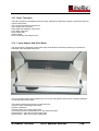
3.11 Operator Panel
The operator panel contains three push button switches with one or two integrated LED's and one BCDswitch.
The push button switches are soldered onto a circuit board, which is mounted behind the front panel. The
BCD-switch is of the snap-in type. It is connected to the circuit board via a plug and cable.
In addition the circuit board has a two position switch (HI/LOW), which is used for various service
settings.
The circuit board is connected to the I/O board via a ribbon cable. Static signals of a 5V TTL-level are
transmitted.
SCAMAX®2600/4000
Tech. Manual 06/2002
T-51
The initial feed belts and the separator rollers cover wear over a period of time. This results in the
distance between feed belts and separator rollers becoming ever greater. The setting on the BCD-switch
has to be decreased to compensate for the wear and tear. When a setting of '0' has been reached the
switch on the circuit board has to be changed from HIGH (factory setting) to LOW and a machine reset
has to be executed (switch scanner off, then on). The previous setting of '0' corresponds now to a setting
of '5'.
The HIGH/LOW switch also activates the following service routines; some of them are described in the
User Manual. Selection of the service routine is via the BCD-switch and initiation of the routine is via the
push buttons (see User Manual, for example white calibration):
BCD-value 9:
BCD-value 8:
BCD-value 7:
BCD-value 6:
White Calibration (see User Manual).
Calibrating the Optical Double Feed Detector (SCAMAX 2500 only).
Cleaning Routine (see User Manual).
Test Scan Routine. Facilitates testing of the mechanical functions of the
Scanner without the need for a PC to be connected to it.
The PC's control functions are simulated in the controller and any errors
Are indicated by the red LED in the start switch being illuminated.
SCAMAX®2600/4000
Tech. Manual 06/2002
T-52
3.12 Optical Components Unit
The optical components unit covers the light path of the front camera and the same for the back camera if
fitted.
Components for both paths and their mode of operation are identical. Merely their positioning in the
scanner is different.
Each path consists of:
a small mirror
a large mirror
a lens 3,5/50 mm with colour filter (bitonal) or 6,4/60 mm (colour).
As can be seen from the drawing each path is broken by two mirrors to keep outside dimensions of the
scanner as small as possible.
In a SCAMAX 2600/4000 duplex version the two miniature fluorescent tubes are held at each end by a
spring-loaded lamp housing. The two lamp holders are connected by a piece of sheet metal that also
prevents unwanted light emission upwards or downwards as appropriate.
The two tubes are somewhat offset and illuminate the front and back respectively of the document being
transported. The light reflected from the document contains the image information. It falls onto the smaller
mirror (1). This mirror transmits the light to the larger mirror (2) (angle of incidence = reflection angle),
which reflects it to the lens. The light captured by the lens is condensed onto the CCD array.
Since the document moves line by line between the two tubes image information is transmitted to the
CCD array of each camera on a line-by-line basis.
The start of the scan process must be exactly timed to be in sync with the feeding of the document. Since
there is no photocell to detect the leading edge of the paper the detection of a certain amount of light in
the CCD is used to signal 'leading edge of paper' (see also 'Flow of a normal scan process').
SCAMAX®2600/4000
Tech. Manual 06/2002
T-53
3.13 Paper Transport
The paper transport unit facilitates document input, followed by initial feed, transport, re-direction and final
output of documents.
The unit has the following components:
Input hopper with drive motor
Paper feed with separation mechanism
Two rubber roller pairs
Paper output path
Output hopper
Drive mechanism with stepper motor
3.13.1 Input Hopper with Drive Motor
The input hopper is designed to allow both single sheet feed as well stack processing. Its operation is
described in the operating instructions.
The input hopper plate is driven up/down by a DC motor with gearbox and eccentric cam discs attached
on the right and left hand sides.
The following switches and sensors control the motor:
1) Switch „Stack mode/Single sheet feed“
2) Switch „Start/Stop“
3) Paper sensor in the input hopper plate
4) Forked photocell at the bearing lever of the initial feed rollers
5) Microswitch - upper limit of input hopper plate
6) Microswitch – lower limit of input hopper plate
SCAMAX®2600/4000
Tech. Manual 06/2002
T-54
The I/O board will send a command to the lift motor in three circumstances
(Motor is running):
1) The switch „Stack mode/Single sheet feed“ is off (single sheet feed). The motor drive the plate
upwards till its pin triggers the top microswitch. Lifting the initial feed rollers, which triggers the forked
photocell (LED is lit) also stops the motor.
2) The switch „Stack mode/Single sheet feed“ is on (stack mode), the "Start/Stop" switch is on (Start:
LED green) and the paper sensor detects one document. The motor will run till the forked photocell is
activated.
3) The switch „Stack mode/Single sheet feed“ is on (stack mode) and the paper sensor detects no
document (end of stack). The motor will run till the lower microswitch is activated. Again, if the initial feed
rollers are lifted the motor will stop.
SCAMAX®2600/4000
Tech. Manual 06/2002
T-55
SCAMAX®2600/4000
Tech. Manual 06/2002
T-56
3.13.2 Diagnosing Paper Input Hopper Faults
Various errors can occur with the paper input hopper. The next three chapters describe these errors and
offer methodologies for diagnosing them.
3.13.2.1 General Faults
Faults described in this section can occur regardless of switch settings on the scanner, as well as with
both GAL versions. The difference between the two GAL versions (2.2 and 2.3) is that version 2.3 checks
the top microswitch as well as the slotted opto-switch. This has been implemented to ensure that the last
document of a batch has been pulled in.
Abreviations used:
TSE:
LSP:
MSD:
MSU:
Table SEnsor (slotted opto-switch at feed belts)
LightSensorPaper (input hopper plate proximity switch)
MicroSwitchDown (microswitch position down)
MicroSwitchUp (microswitch poistion top)
The most common cause of microswitch faults is that its lever is bent. This will prevent the switch from
being activated.
Fault
Table does not drive
Motor runs, table
stationary
Table falls down
Cause
Defective TSE permanent (low), motor defective; faulty lead; fault on I/O:
stabiliser IC5, IC6; capacitors C8-C11; Z-Diode DZ1; ULN2803A IC7
Drive shaft’s or motor’s gear wheel loose; motor mounting not fastened
properly
Motor and/or drive shaft gear wheels loose
SCAMAX®2600/4000
Tech. Manual 06/2002
T-57
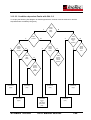
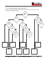
3.13.2.2 Condition dependent Faults with GAL 2.2
To employ the following flow diagram for fault diagnostics the scanner must be switched on and the
stop/start button activated (LED green).
Y
Paper
present
Y
Y
Table
stays in
down
position
Y
LSP faulty
permanent
(high)
Y
Y
Y
N
SCAMAX®2600/4000
Table
drives
all the
timey
Y
N
Table
doesn’t
drive to
top
position
Y
Table
doesn’t
drive to
bottom
position
Table
doesn’t
drive to
top
position
MSU faulty
permanent
(low)
TSE faulty
permanent
(high)
N
N
N
Table
jams
stack
Stack
mode
(auto
feed)
MSD faulty
permanent
(low)
MSD faulty
permanent
(high)
or
LSP faulty
permanent
(low)
Tech. Manual 06/2002
MSU faulty
permanent
(high)
MSU faulty
permanent
(low)
T-58
N
Table
drives
all the
time
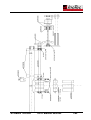
3.13.2.3 Condition dependent Faults with GAL 2.3
To employ the following flow diagram for fault diagnostics the scanner must be switched on and the
stop/start button activated (LED green).
Stack
mode
(auto
feed)
Y
Y
Y
Table
stays in
down
position
N
Y
Table
jams
stack
Y
LSP faulty
permanent
(high)
Paper
present
N
Y
N
Y
Table
drives
all the
time
Y
Table
doesn’t
drive to
top
position
SCAMAX®2600/4000
N
Table
doesn’t
drive to
bottom
position
Y
MSU faulty
permanent
(low)
TSE faulty
permanent
(high)
N
Y
N
Table
drives
to top
position
MSD faulty
permanent
(low)
MSD faulty
permanent
(high)
Table
doesn’t
drive to
top
position
MSU faulty
permanent
(high)
LSP faulty
permanent
(low)
Tech. Manual 06/2002
MSU faulty
permanent
(low)
T-59
N
Table
drives
all the
time
3.13.3 Paper Feed with Separation System
The initial feed rollers, consisting of three red rubber belts, are mounted on two levers. Its own weight
presses it onto the top document.
The lowest position of the initial feed rollers can be adjusted vertically via two set-screws (see above
"Document Feeder Adjustment"). This adjustment is necessary to prevent the feed belts rubbing directly
on the input hopper plate when no paper is present.
Paper feed is activated via an electromagnetic clutch located at the end of the shaft (see also "Flow of a
scan routine"). Power transmission to the clutch is via a gear wheel. It is separated from the drive
mechanism when the output hopper plate is lifted.
There are normal feed rollers made from aluminium and there are heavy feed rollers made from steel,
which are approximately three times heavier. With difficult or unusual paper the heavier edition can
improve paper feed due to the greater pressure being exerted.
The performance of the paper separation is largely dependent on many factors, but ultimately dictated by
the slip and/or sticking together of documents. If heavier pressure produces better results with one kind of
paper it may cause the opposite with another kind. The standard issue of aluminium rollers has been
proven to be the best compromise available for the majority of documents encountered.
The pushback roller, which prevents two or more documents being fed simultaneously, plays an important
part in paper separation. It is covered with a friction coating and its distance to the initial feed rollers can
be adjusted depending on paper thickness. The pushback roller turns slowly against the paper travel
direction. The main drive powers it via a round belt.
Normally the pushback rollers have yellow friction coatings. For documents difficult to separate there
are white friction coatings available that offer greater traction that pushes paper back firmer. Life
expectancy of the white covers is much shorter than for the yellow ones.
The paper thickness selector sets the distance between pushback roller and feed belts. A stepper motor
drives two eccentric discs via a toothed belt and drive shaft. The discs hold the pushback roller, shaft and
bearing in position against the pull of two springs.
When the scanner is turned on, or after a reset, the stepper motor executes a reference drive whereby a
nose on the left eccentric disc activates a microswitch. This position is also the position assumed when
paper separation is off, i.e. it represents the largest distance between feed roller and pushback roller.
SCAMAX®2600/4000
Tech. Manual 06/2002
T-60
The paper thickness selector can be set to values between 0 and 9. The common setting for 80 gsm
paper is '5'. To achieve this the entire adjustment area can be shifted in twelve steps via a parameter.
This is necessary to allow for unavoidable manufacturing tolerances.
The two guide plates in the area of the separation mechanism float the documents to the first pair of
rubber rollers. To ensure that even thin paper travels in the right direction the two guide plates, the top
and bottom one have seven finger-like extensions at their ends. These extensions prevent thin paper
wrapping itself around one of the rubber rollers.
Abstandseinstellung für S26/S40
SCAMAX®2600/4000
Tech. Manual 06/2002
T-61
SCAMAX®2600/4000
Tech. Manual 06/2002
T-62
3.13.4 Rubber Roller Pairs (two)
There are two rubber roller pairs, one just prior to the two fluorescent tubes and another one behind the
tubes.
The front rubber rollers each have seven cylindrical cut-outs that accommodate the seven finger
extensions of the guide plates.
The rear rubber rollers have a cylindrical form.
The main drive belt drives the bottom roller only of each rubber roller pair. The top rollers are idlers,
pressed against the bottom roller by two springs each.
In certain circumstances documents containing aggresive inks, coloured coatings or solvents like selfcorbonising paper can cause problems.
These agents can cause swelling of the rubber rollers. For these situations special rubber rollers are
available made from Viton, which is a relatively resistant material.
3.13.5 Paper Output Path
Antrieb Umlenkstrecke
Fünf gelbe
Transportbänder
Zahnrad
SCAMAX®2600/4000
Tech. Manual 06/2002
T-63
Power is transmitted from the main drive via a cogged-wheel to the lower roller. The five transport belts
travel over the rear guide plate and transmit drive power to the other rollers.
The top roller is housed in separate shaft housings (with ball bearings and diaphragm spring). The roller
is pushed into the shaft housings.
The second roller from the top, aft is also housed in shaft housings. However, they have oblong mounting
holes that allow positioning of the roller. This is used to adjust the tension of the transport belts.
3.13.6 Output Hopper
Scanned documents are deposited onto the output hopper plate in the order they were scanned. The
output hopper plate automatically descends as the output stack height increases, due to the increasing
weight of the paper. This methodology provides as falt an output path as possible, prevent thin
documents from rolling up or turning over.
Depending on the type of documents a suitable adjustment can be made. An adjustment screw to trim for
the average paperweight is found inside the scanner on the right hand side.
After lifting and pushing back the output hopper plate the knurled nut is loosened. For small or thin
documents the screw is pushed upwards in the oblong hole and the knurled nut is tightened again.
In this top position only the two large springs are active, one at the left and right of the sidewall
respectively.
Lowering the screw with the knurled nut activates the two smaller springs, one each at the left and right
hand side, as well.
To prevent injury the transport motor is switched off as soon as the output hopper plate is lifted. This
action is triggered by the newly installed microswitch on the left-hand side above the microswitch that
stops the input hopper plate when single sheet feed is selected.
SCAMAX®2600/4000
Tech. Manual 06/2002
T-64
3.13.7 Drive Mechanism with Stepper Motor
A stepper motor drives the total paper transport including the document feeder. Transport speed is
adjusted to the resolution selected and is trimmed via a parameter.
The drive system has the following components:
a stepper motor
a flat belt drive
a round belt
an electromagnetic clutch with gear
The stepper motor is mounted on the inside of the right hand side sidewall. Rubber elements are used to
provide cushioning.
This aids in noise reduction.
When a scan command is issued the stepper motor starts. A flat woven belt transmits the drive power to
the following parts:
- the first shaft of the paper return mechanism
- the two robber roller pairs
- the electromagnetic clutch that drives the initial feed rollers
- via a round belt to the push-back roller
Tension of the flat belt can be adjusted by moving the stepper motor. If tension is too loose the belt can
slip, which can result in distortion of the scanned image or the scanner issuing an 'over length document'
message.
The following illustration is a side view from the right showing the drive with the cover open.
SCAMAX®2600/4000
Tech. Manual 06/2002
T-65
SCAMAX®2600/4000
Tech. Manual 06/2002
T-66
SCAMAX®2600/4000
Tech. Manual 06/2002
T-67
3.14 Description of Scan Routine Flow
The scan routine is initiated by the PC via the scanner interface (DPU, HiScan or dunord) or via the inbuilt
SCSI-Interface. Originally, of course, the operator and the user program issue the command.
First the scan status is tested. If, since the last scan process, a document has passed through the
scanner unchecked the scanner issues a „Paper not scanned“ (E4) message. The „No Paper“ (E0) error
message is issued if the paper sensor hasn't detected any paper or if the start switch has not been
depressed.
If no error is present the stepper motor is started if it is not already running. The magnetic clutch is
engaged and the feed belts pull in a document. If the ultrasound double feed detector senses a double
feed before a document reaches the scan area (image window of the CCD) the motor is stopped and the
error message „Doublefeed“ (E3) is issued.
The error message „Timeout“ (E1) is issued if the document does not reach the scan area within 7.5
seconds.
As soon as at least 256 pixels in a line have a grey level above the H-Gate threshold (default value is
100) the clutch is disengaged and the scan process proper starts. Image data are then received by the
SCSI interface or scanner interface in the PC.
At the scan mode default setting (with length check) the selected number of lines (for example 2,400 lines
for A4) will be transmitted.
When the number of lines, plus an offset of for example 50 lines, has been reached a check is made
whether there is more paper in the scan area. If there is paper present for more than two seconds the
motor is switched off and the error message „Paper jam“ (E5) is issued.
If paper is present for less than two seconds the condition is classed as "only" oversized, which can have
several reasons. The error message „Oversize“ (E2) is issued in this case.
The length check can be turned off via the software. In that case only the number of lines appropriate for
the document size are transmitted. A black line or stripe across the document can, in this mode, cause a
scan end since the paper recognition only sees black. In this mode a „Paper jam“ is only recognised after
10 seconds have elapsed.
If the ultrasound double feed detector has responded during the scan process the error message
"Doublefeed" (E3) is issued after scanning has ended.
If no error where detected during the scan process „Ready“ (8A) will be issued.
SCAMAX®2600/4000
Tech. Manual 06/2002
T-68