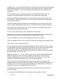
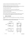
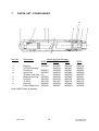
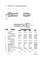
1
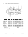
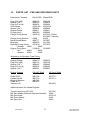
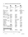
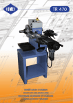
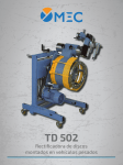
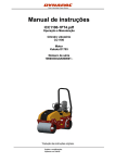
OPERATOR'S SPARE PARTS & SERVICE MANUAL Type ‘W’ Vibrating Pokers and Drive Units FAIRPORT CONSTRUCTION EQUIPMENT LTD Blagden Street Sheffield S2 5QS ENGLAND Tel: +44 (0) 114 276 7921 Fax: +44 (0) 114 272 0965 Email: [email protected] Website: www fairport uk com M-WPTpkrws Issue 3225-Jul 01 'W' RANGE POKER MANUAL CONTENTS 1. 2. 3. INTRODUCTION ................................................................................................. 2 TECHNICAL DATA.............................................................................................. 2 SAFETY .............................................................................................................. 3 3.1 FLEXIBLE CASING USED ON POKER VIBRATORS - COSHH REGULATIONS ...................................................................................................... 4 3.1.1 Data Sheet On Flexible Casing ............................................................. 4 3.1.2 Fire........................................................................................................ 4 3.1.3 Storage Throttle Lever stop................................................................... 4 3.1.4 Waste Disposal ..................................................................................... 4 3.2 SAFETY PICTOGRAMS USED ON THIS EQUIPMENT.............................. 6 4. COMMISSIONING AND OPERATING INSTRUCTIONS .................................... 6 4.1 POKER DRIVE UNIT - PETROL OR DIESEL .............................................. 6 4.2 POKER DRIVE UNIT - ELECTRIC............................................................... 7 4.3 STARTING THE VIBRATING POKER ......................................................... 7 4.4 USER HINTS AND INSTRUCTIONS ........................................................... 8 5. GENERAL MAINTENANCE ................................................................................ 8 5.1 FLEXIBLE DRIVE SHAFT TYPE W525 - W536 - W545 ............................. 8 5.2 FLEXIBLE DRIVE SHAFT TYPE W560 ..................................................... 10 5.3 POKER HEAD TYPE W536, W545 & W560 .............................................. 10 5.4 POKER HEAD TYPE W525 ....................................................................... 11 5.5 PLUG-IN CONNECTOR............................................................................. 11 6. WIRING DIAGRAMS ......................................................................................... 12 7. PARTS LIST - POKER HEADS......................................................................... 13 8. PARTS LIST - FLEXIBLE DRIVE SHAFT ......................................................... 14 9. PARTS LIST - PLUG IN CONNECTORS (P.I.C.s)............................................ 16 10. PARTS LIST - PSD AND DSD DRIVE UNITS................................................... 17 11. PARTS LIST - ESD & ECD ELECTRIC DRIVE UNITS ..................................... 18 12. PARTS LIST - EMD DRIVE UNIT ..................................................................... 19 13. WARRANTY CONDITIONS AND CLAIMS PROCEDURE................................ 20 CONDITIONS ....................................................................................................... 20 CLAIMS PROCEDURE......................................................................................... 21 14. REPAIRS AND ESTIMATES............................................................................. 21 Please note that the ECD type unit is obsolete as from serial number 62856 and is replaced by the EMD type unit. M-WPTpkrws 1 Issue 3225-Jul 01 Issue 3523 Dec 05 1. INTRODUCTION The ‘W’ range of internal concrete vibrators (pokers) is petrol engine or electric motor powered and drive is transmitted to the vibrating head using a flexible shaft. The ‘W’ system has four main components: a) b) c) d) A vibrating poker head A flexible drive shaft A quick action coupling A drive unit. The quick action coupling is disconnected from the drive unit by hand. Spanners are required to remove the coupling from the flexible shaft and this may be carried out on site. Further dismantling should be carried out in a workshop. Four models of poker are available, W525, W536, W545 and W566. The last two numbers of the model designation indicates the poker diameter in millimetres. The ‘5’ indicates the nominal length of the flexible drive, which in this case, is the standard length of 5 metres. Special lengths are available to order. Couplings are available that will screw on to the flexible drive and plug in to alternative makes of drive unit. The alternatives that are available are shown on the parts list in this manual. This manual is concerned with the safe use and routine maintenance of this equipment. It is recommended that poker heads that require repair be returned to one of the Fairport depots at either Sheffield or Edenbridge. 2. TECHNICAL DATA Drive Units - Petrol/Diesel Engine Make/Type L mm W mm H mm Wt kg Net BHP @2800rpm Honda GX160 410 510 535 26 4.0 Yanmar L40 410 510 535 42 3.4 Hatz 1B30 460 460 470 TBA 6.3 Petter AC1 520 480 550 70 5.2 LwA levels based on engine manufacturers’ data. LwA DB (A) 98 96 TBA 102 Drive Units - Electric Electrical data Length: M-WPTpkrws ECD 0.75kw, 115/230v, 12.6/6.3A, 1ph 360mm EMD 0.75kw, 115/230v, 12.6/6.3A, 1ph 365mm 2 ESD 1.5kW,various voltages, see motor plate 360mm Issue 3225-Jul 01 Issue 3523 Dec 05 Width: Height: Weight: LwA: Switch insulation Motor insulation 245mm 380mm 17.7 kg less than 85dB(A) IP66 IP55 Poker Sound Levels dB (A) W560 245mm 315mm 17.0 less than 85dB(A) IP66 IP55 W525 360mm 350mm 23kg less than 85dB(A) IP65 IP55 W536 W545 In concrete: Operator position LpA: Power level LwA: 67.8 80.0 75.0 87.5 75.6 88.4 79.4 94.4 74.0 86.6 79.0 90.8 85.0 98.0 87.2 99.2 7.0 7.0 5.5 5.5 In air: Operator position LpA: Power Level LwA: Hand/arm vibration levels, m/sec2 maximum axis: In concrete: In air: 4.0 4.0 5.0 5.0 Sound levels tested according to ISO 5349 Vibration levels tested according to ISO 3746 3. SAFETY Never run petrol or diesel engines in trenches or confined spaces. Never attempt to carry out maintenance with engine or motor running. Never top up fuel tank whilst engine is running; don't smoke; wipe up spilt fuel. Dispose of fuel contaminated wipes safely. Always turn off fuel after use. Always isolate electric motors after use. Always use residual current devices with electric motors. Always wear suitable protective clothing, i.e. safety helmet, footwear, ear defenders and gloves. Ensure guards are always fixed in position when engines/motors are running. M-WPTpkrws 3 Issue 3225-Jul 01 Issue 3523 Dec 05 Always comply with site safety regulations. Do not attempt to carry out repairs to electric drive units unless you are a competent electrician. 3.1 FLEXIBLE CASING USED ON POKER VIBRATORS - COSHH REGULATIONS This data sheet provides the information required on Section 6 of the Health and Safety at Works Act 1974 as amended by Schedule 3 of the consumer Protection Act 1987. 3.1.1 Data Sheet On Flexible Casing The Polymeric compounds used on hose may contain materials that can migrate to the surface from whence they could be transferred to the skin during handling. This may cause skin irritation to persons who frequently handle hose. Persons who have to handle the hose frequently are advised to follow good hygienic practices e.g. wear gloves whenever practicable. Use barriers cream and wash hands after work before eating, drinking or smoking. 3.1.2 Fire With a few exceptions the polymeric materials used by Dunlop Hose Limited are not easy to ignite in bulk. However when exposed to flame or to serious overheating they will decompose liberating noxious or toxic smoke or fumes. Fire precautions should recognise the hazards that may arise from indirect involvement in a fire as well as the inherent fire risk of the individual products. Specialised advice on fire precautions is available from local Fire Authorities and from Health & Safety Executive. 3.1.3 Storage Hose may deteriorate in appearance and physical properties during storage particularly if adverse storage conditions apply. BS3574 details the most suitable conditions for storage. In summary, hose should be stored in an unstressed darkened condition below 25° C and protected from moisture and air circulation. Expose to atmosphere containing high concentration of ozone (eg. near discharge from electric motors) is to be particularly avoided. Hose should be stored away from direct heat and contact with strong oxidising agents should be avoided. 3.1.4 Waste Disposal Hose should be disposed of by normal waste disposal procedures. Where M-WPTpkrws 4 Issue 3225-Jul 01 Issue 3523 Dec 05 incineration is used the incinerator must be specifically designed to give complete combustion of the gases and fumes produced. M-WPTpkrws 5 Issue 3225-Jul 01 Issue 3523 Dec 05 3.2 SAFETY PICTOGRAMS USED ON THIS EQUIPMENT Wear Gloves Wear ear protectors Read the manual before using this equipment 4. COMMISSIONING AND OPERATING INSTRUCTIONS The machine as delivered will generally be in two main assemblies: a) The drive unit b) The poker head complete with flexible shaft drive and coupling. To assemble the flexible poker drive to the power unit, raise the latch knob on the coupling housing on the engine and insert the coupling attached to the end of the flexible drive. On releasing the knob the plunger should locate itself in the groove in the plug-in connector. When connecting to a petrol or diesel engine it may be necessary to rotate the engine crankshaft by means of the rope or handle starter at the same time applying pressure to the coupling in order to obtain engagement. Check the engagement by pulling on the coupling after releasing the latch knob. The coupling must never be inserted into or removed from the housing with the engine or electric motor running. If the coupling is disconnected from the flexible shaft at any time, be sure to protect all exposed ends from possible damage or entry of foreign matter. When transporting flexible poker shaft assemblies, it is essential that they are never coiled too tightly, likewise acute bends should be avoided when operating on site. The recommended method of storing these flexible shafts is on timber racks so that the shaft is kept straight and supported throughout its full length. 4.1 POKER DRIVE UNIT - PETROL OR DIESEL Carefully read the engine manufacturer's instruction book before starting. M-WPTpkrws 6 Issue 3225-Jul 01 Issue 3523 Dec 05 Check oil level. Turn fuel tap on. Put speed control lever to tick-over. If engine is cold, close the choke (petrol engines only). Turn engine switch to ON (1) position. Pull the starter rope toggle lightly until resistance is felt, then pull briskly using quick short pull. Do not pull rope to its full extent or allow toggle to snap back against engine. Return it gently to avoid damage. When engine is warm open choke. Position engine speed control lever to give required engine speed (usually full speed, but see note below). To stop engine, position the engine speed control to slow and turn the engine switch to off (0). Turn the fuel valve to off. NOTE: The governors of petrol and diesel engine drive units have been set at 2,750/2,850 rpm maximum. It is essential that the engine speed is not increased over 3,000 rpm as this will induce stress which may result in the failure of the poker head or flexible shaft and therefore invalidate any warranty. CHECK ENGINE SPEED. 4.2 POKER DRIVE UNIT - ELECTRIC The electric motor supplied is a totally enclosed, fan-cooled type, operating at a continuous rated speed of 2,850 rpm. Check that the voltage, number of phases and frequency requirements of the motor being used are compatible with the supply. When making electric connections, it is essential that the output shaft runs in an anticlockwise direction when viewing the drive claw through the open end of the housing. Always use a cable of sufficient cross section to avoid excessive voltage drop. This is the major cause of electrical problems and motor overloading with 110v supplies. If in doubt consult a qualified electrician. 4.3 STARTING THE VIBRATING POKER With the coupling correctly inserted into the housing start the engine or switch on the electric motor. During cold weather it is advisable to run petrol or diesel engines for a few minutes before connecting the flexible drive. M-WPTpkrws Issue 3225-Jul 01 7 Issue 3523 Dec 05 If the poker head does not start vibrating when the drive unit is at full speed tap the nose cap on a hard surface. Avoid tapping the body of the poker head, as this has not been hardened. 4.4 USER HINTS AND INSTRUCTIONS Use the largest poker that the job and reinforcement will allow. Move the poker frequently. A little and often over an area is better than holding it in one place for a long time. Make sure the whole area is covered. Withdraw the poker slowly to ensure the hole is closed with adequately vibrated concrete. When using a poker with timber formwork make sure the poker does not damage the formwork. Consider using a poker with a polyurethane nose cap – contact Fairport or your dealer. When vibrating a layer of concrete, which has been poured onto a previously vibrated layer, ensure the poker penetrates the previous layer by about 100mm. Do not try to vibrate concrete in layers greater than 300mm to 400mm. Try to immerse the whole of the poker head in the concrete to provide some cooling. Do not leave the poker running when it is not in concrete. This will prevent overheating of the bearings. Avoid tight bends in the flexible drive shaft. Tight bends cause rapid wear of the flexible core. Check on a regular basis (weekly) that all joints on the flexible drive are tight. Do not allow the coupling end of the flexible drive to lie in wet conditions on the ground, as the entry of water to the bearings will cause rusting. Do not stop the vibration whilst the poker is still in the concrete. It may prove difficult to remove and it will leave a void. 5. GENERAL MAINTENANCE 5.1 FLEXIBLE DRIVE SHAFT TYPE W525 - W536 - W545 (Refer also to Parts List) The flexible drive shaft should be dismantled and re-charged with grease every 500 M-WPTpkrws Issue 3225-Jul 01 8 Issue 3523 Dec 05 working hours. As it is extremely difficult to keep accurate records, we would suggest that the flexible poker drive be overhauled at set regular intervals. This will ensure trouble free operation. The recommended grade of grease is Castrol BM2 or an equivalent. Do not attempt to carry out the lubrication of the flexible shaft drive under site conditions; this should always be carried out in a maintenance workshop. When dismantling the flexible poker drive, first remove the plug-in connector (left hand thread). The complete plug-in connector assembly may then be pulled away from the flexible shaft. Hold the bearing housing of the poker head assembly in a vice, then unscrew the poker housing, complete with nose cap, in a clockwise direction (left hand thread). Next unscrew the flexible drive outer case coupling from the bearing housing in a clockwise direction (left hand thread). Pull the outer casing away so as to expose the core coupling. Hold the core coupling in a vice and unscrew the pendulum, complete with bearing and oil seal etc., in an anti-clockwise direction (right hand thread). The inner flexible core can now be withdrawn from the outer casing. Clean the flexible steel inner core and core couplings thoroughly with grease solvent. Clean ends of outer casing with a cloth. After thoroughly cleaning the complete flexible drive shaft, inspect the inner core for any excessive wear due to rubbing action between the core and outer casing spiral reinforcement; also for damaged and broken outer layer wires. If there is a permanent bend in the outer casing we advise fitting a replacement, as this is liable to cause damage to the inner core. Regrease the first 12" - 18" (30 - 40cm) of the inner core with Castrol BM2 grease. Insert the greased inner core into the casing from the plug-in connector end. Continue greasing the inner core and at the same time insert it into the casing. Continue until the whole length of inner core has been greased. As the inner core is pushed through the outer casing, some of the grease will naturally adhere to the inner walls of the casing. To ensure adequate lubrication, it is advisable to draw out the core for approximately 6ft (2 metres) from the other end, regrease as the core is inserted back into the casing. It is essential during the regreasing operation to keep dirt and grit away from the component parts. To re-assemble the flexible drive to the poker head, proceed as follows: M-WPTpkrws 9 Issue 3225-Jul 01 Issue 3523 Dec 05 Renew the 'O' ring in the groove at the lower end of the external thread in the outer case coupling (poker head end). Pull out the inner core for about 4" (10cm) and screw the core coupling (right hand thread) on to the exposed end of the pendulum, then screw the outer case coupling into the bearing housing in an anti-clockwise direction (left hand thread). During this operation, ensure not to damage the fine thread. Before replacing the poker housing, wipe the pendulum with a clean dry cloth to remove any traces of grease or dirt. The interior of the poker housing and nose cap must be cleaned in a similar manner. Traces of grease on either of these components will upset the operation of the vibrating poker. Renew the 'O' ring fitted between the poker housing and the bearing housing, also the one fitted to the nose cap. These rings must be in good condition to ensure a satisfactory seal between the various components. When screwing on the plug-in connector to the other end of the flexible poker drive. Ensure that the keyway is fully engaged with the internal key of the main shaft. 5.2 FLEXIBLE DRIVE SHAFT TYPE W560 (Refer also to Parts List) The frequency of re-greasing and the grade of lubricant recommended are as quoted in the previous section. The operations for dismantling and cleaning are as described above except that this particular flexible drive shaft is fitted with an additional connector nut. This component has to be unscrewed from the bearing housing in an anti-clockwise direction (right hand thread) prior to removal of the outer case coupling. 5.3 POKER HEAD TYPE W536, W545 & W560 (Refer also to Parts List) When dismantling a poker head, first remove the flexible drive shaft as described in section 5.1 and 5.2. The pendulum can be removed by supporting the bearing housing and applying pressure to the threaded end of the pendulum. NOTE: It is important to ensure that the screw thread is not damaged during this operation. The bearing, oil seal and oil seal carrier can be easily removed from the bearing housing. After cleaning all the poker head parts thoroughly in grease solvent, inspect the components for possible wear or damage. M-WPTpkrws Issue 3225-Jul 01 10 Issue 3523 Dec 05 The double row self-aligning bearing that supports the pendulum is to a specification that limits the diametral clearance between the inner and outer tracks. If a standard bearing were used as a replacement, the efficiency of the poker would be impaired. Do not forget to replace the Shake proof washer. We recommend the replacement of the bearing, oil seal and 'O' rings whenever a poker is dismantled. When re-assembling the poker head, pack the double row self-aligning bearing with Castrol BM2, or equivalent. Before replacing the poker housing, ensure that both the pendulum and the interior of the housing, including the nose cap, are clean and free from all traces of grease, as the presence of grease will severely affect the efficiency of the poker. Do not forget to fit new 'O' rings to ensure that all joints are watertight. 5.4 POKER HEAD TYPE W525 (Refer also to Parts List) The procedure for dismantling the 525 type poker head is similar to that described for larger models. However a separate oil seal housing is not fitted to type 525. The oil seal fits directly into the bearing housing. In addition, a plain and shake proof washer is fitted between the self-aligning bearing and the shoulder formed in the bearing housing. When re-assembling the poker head, it is essential that the washer be positioned correctly; failure to do so may result in it restricting the angular movement of the pendulum. As mentioned in the various sections it is essential to thoroughly clean all the parts prior to re-assembly and grease the bearings with the recommended lubricant. 5.5 PLUG-IN CONNECTOR (Refer also to Parts List) Should it be necessary to dismantle the coupling, proceed as follows: Unscrew main shaft head and remove internal circlip. Press out the main shaft complete with bearings etc., by means of an arbour or fly press. When carrying out this operation support the large diameter of the housing and apply pressure to the small end of the shaft. Next remove the circlip and withdraw the key retaining collar, the key itself can now be withdrawn from its locating keyway. The bearings and spacer can now be pressed off the main shaft. M-WPTpkrws 11 Issue 3225-Jul 01 Issue 3523 Dec 05 Check the condition of the two ball bearings, and replace if necessary. Reassembly is generally the reverse of the above procedure. After fitting the ball bearing and spacer the driving key can be inserted in the keyway and the key-retaining collar replaced to hold the key in position. Fit the circlip to retain the collar. Fill the space between the two bearings with Castrol BM2 grease. Press in the bearing sub-assembly into the housing until the inner bearing is in contact with its locating shoulder. Refit internal circlip and screw on main shaft head. When screwing on the plug-in connector to the flexible drive shaft, be sure that the core coupling keyway is fully engaged with the internal key of the main shaft. 6. WIRING DIAGRAMS The electric motors used on ECD and EMD units are dual voltage. Check wiring as below. If a wiring diagram is required for an ESD type please contact Fairport Construction Equipment Ltd quoting voltage, kilowatts and serial number. M-WPTpkrws 12 Issue 3225-Jul 01 Issue 3523 Dec 05 7. PARTS LIST - POKER HEADS Ref. No Description W525 1 2 3 4 5 6 7 8 Bearing Oil Seal Housing Pendulum Nose Cap 'Rubber' nose cap Bearing Housing Oil Seal 'O' Ring Housing Poker Head Ass'y Model and Part Number W536 W545 W81065 W60261 W60263 n/a W60264 W81232 W81132 W60262 W60260 W81062 W60234 W60228 W60233 W60815 W60235 W81233 W81107 W60229 W60227 W81063 W60247 W60241 W60246 W60786 W60248 W81234 W81134 W60242 W60240 W560 W81064 W60210 W60201 W60209 W60785 W60211 W81209 W81135 W60205 W60200 Note: W560 Poker illustrated M-WPTpkrws 13 Issue 3225-Jul 01 Issue 3523 Dec 05 8. PARTS LIST - FLEXIBLE DRIVE SHAFT Ref. No Description W525 1 2 3 4 5 7 8 9 10 11 12 14 15 16 17 18 Complete Drive, 5mtr.long O/Casing complete, 5mtr long Keyway Core Cplg Threaded Core Cplg Bearing Circlip - External Casing Coupling Poker End Casing Coupling Motor End Spiral Protector Half Clamps (2 off) Taper Sleeve Connector Nut Reinforcement Sleeve Inner Core complete 5mtr 'O' Ring Shake proof Washer 425/8 Plain Washer M-WPTpkrws Model and Part Number W536 W545 W560 W60791 W60790 W60790 60792 W60844 W62010 W62011 none none W60849 W62016 W62017 W81070 W81314 W60849 W62016 W62017 W81070 W81314 W60852 W62016 W62021 W81070 W81314 W62012 W62018 W62018 W62018 W62100 W62014 n/a n/a n/a n/a W60842 W81132 439/6 W62093 W62020 n/a n/a n/a n/a W60846 W81107 425/6 W62093 W62020 n/a n/a n/a n/a W60846 W81107 425/6 W62093 W62020 W62022 W62023 W62024 W60040 W60850 W81107 418/6 419/6 419/6 418/12 14 Issue 3225-Jul 01 Issue 3523 Dec 05 Note: W560 Flexible Drive illustrated. M-WPTpkrws 15 Issue 3225-Jul 01 Issue 3523 Dec 05 9. PARTS LIST - PLUG IN CONNECTORS (P.I.C.s) Warsop plug-in connector illustrated. Description 1 2 3 4 5 6 7 8 9 10 11 Warsop P.I.C. No W60803 Mainshaft Head W60358 Main Shaft W60746 Bearing W81066 Spacer W60385 Bearing W81066 Int. Circlip W81256 Spindle Adaptor n/a Collar W60747 Drive Key W60011 Housing W60798 Ext.Circlip W81312 Caphead screw Tolerance ring Spacer (fits behind dog) M-WPTpkrws Errut W60802 W60437 W60438 W81066 W60385 W81066 W81256 W60461 W60012 W60011 W60799 W81312 Dynapac W60801 W60453 W60454 W81066 W60385 W81066 W81256 W60461 W60012 W60011 W60800 W81312 Wacker Fyne W60813 W60453 W60454 W81066 W60385 W81066 W81256 W60461 W60012 W60011 W60812 W81312 92961 W50646 W60462 W81006 W60466 W81006 n/a n/a W60870 W60033 W60866 W81400 450/6/8 W80616 Metrix 92844 W50637 W60746 W81060 W51056 W81060 W81253 n/a W60747 W60011 W51055 W81312 CEL 93036 W60453 W60454 W81066 W60385 W81066 W81256 W60461 W60012 W60011 W60800 W81312 W60875 16 Issue 3225-Jul 01 Issue 3523 Dec 05 10. PARTS LIST - PSD AND DSD DRIVE UNITS Description: Warsop Petrol PSD Diesel DSD Dog (5/8" UNF) Spacer (5/8") Dog (3/4" key'd) Grub Screw Spacer (3/4") Engine Flange Plunger Assy Flange Fixing Screw W60163 W60819 W60434 462/6/12k W60804 W60411 W60020 408/5/16 Flange Fixing Washer Metal Rubber Base Birdcage Birdcage Fixing Screw " “ Washer 439/8 Engine Fixing Stud " “ Nut 440/8 " “ Washer 439/8 W60163 W60819 W60434 462/6/12k W60804 W60411 W60020 407/5/16 (Petter) 437/8/25 (Yanmar) 439/8 W13037 W11224 437/8/16 439/8 W60777 W60818 437/8/16 439/8 519/8/45 519/8/45 440/8 439/8 Alternative for Dynapac Type Fitting Engine Flange Dog (5/8" UNF) Spacer (5/8") Dog (3/4" key'd) Spacer (3/4") W60479 W60153 W60445 W60434 W60821 W60479 W60153 W60445 W60434 W60821 Engine Options 5/8 UNF Shaft 3/4 Key'd Shaft Robin EY20 Honda GX160 Briggs & Stratton Petter AC1 Yanmar L40 W81798 W81732 W81785 W81855 W81776 W81731 W81843 Additional Items for Honda Engines: Throttle Lever stop (GX160) M6 Star Washer (between stop and bracket) M6 Hex Screw M6 Plain Washer M6 Nyloc Nut M-WPTpkrws 17 W51785 439/6 437/6/16 418/6 480/6 Issue 3225-Jul 01 Issue 3523 Dec 05 11. PARTS LIST - ESD & ECD ELECTRIC DRIVE UNITS Model ESD ESD ECD Electrical data: volts kW amps phase Hz 380-415 1.5 5.5-5.2/3.2-3.0 3 50 110-115/220-230 1.5 27.2/13.6 1 50 110/220 0.75 12.8/6.4 1 50 Dog W60820(1) Metal/Rubber Base W60881 Frame Assembly W60773 Handle Handle Grip Handle Fixing Screw Washer Motor/Flange Adaptor W60780 Fixing for Frame:Set Screw 437/8/12 Washer 439/8 Adaptor to Motor Fixing 455/8/16 Motor W81946 Fixing for Motor: Screw 437/8/20 Washer 439/8 Nut Switch/Starter W60752 Switch/Starter For Fixing Switch: Screw 449/5/16 or Starter Nut 480/5 Conduit Nut 531/20 Cable Gland W17276 110v Plug 230v Plug 380/415v Plug W81957 Flange W60687 Plunger Assy W60020 Fixing for Flange:Set Screw 437/6/25 Washer 439/6 Cable, state length required W80095 W60820(1) W60881 W60773 W60780 437/8/12 439/8 455/8/16 W82104 437/8/20 439/8 W17271 (110v) W17272 (230v) 449/5/16 480/5 531/20 W17276 W19724 W19706 W60150 Metal Base W60693 W60793 W19278 W80148 437/12/25 439/12 W60735 469/8/25 418/8 480/8 W60686 455/5/25 480/5 W13408 W19704 W19706 W60687 W60020 437/6/25 439/6 W82101 W60687 W60020 437/6/25 439/6 W60334 W60741 W60820(2) W60153 W60153 W60851 Alternative Dynapac Type Fittings Flange Dog Spacer W60741 W60820(2) (1) Distance between back of Dog and shaft shoulder is set at 8mm (2) " " " " " " " " " " " 15mm M-WPTpkrws 18 Issue 3225-Jul 01 Issue 3523 Dec 05 12. Item 1 2 3 4 5 5 6 --7 8 9 10 11 12 13 14 15 16 17 18 19 20 PARTS LIST - EMD DRIVE UNIT Part No Description W60879 Motor cover W80617 Handle W13408 Cable gland - output from switch W60686 Switch W19704 Plug, 110v W19706 Plug, 230v W455/5/25 M5 X 25 SKT HD CAP Screw W439/5 M5 SHAKE PROOF WASHER P100-0005-01 M5 WASHER W82179 Cable gland - supply W60334 Cable - state length required W82178 Motor - state voltage required 469/8/30 M8 X 30 csk screw 480/8 M8 Nyloc nut 420/8 M8 washer W60693 Base W60150 Drive dog - Warsop W60687 Flange - Warsop W60020 Plunger W437/6/25 M6 hex set screw W439/6 M6 Shake proof washer W439/6 M6 Shake proof washer W4376/12 M6 hex set screw M-WPTpkrws 19 Issue 3225-Jul 01 Issue 3523 Dec 05 Alternative Dynapac Type Fittings W60741 W60153 W60851 13. Flange Drive dog Spacer - fits behind dog WARRANTY CONDITIONS AND CLAIMS PROCEDURE All products supplied by Fairport Construction Equipment Ltd (hereafter referred to as FCE) are warranted to be free of defects due to faulty materials or workmanship for a period of 12 months from the date of original despatch from FCE or as specified below: Hydraulic hoses and hydraulic couplings – 3 months. Hydraulic accumulators – 6 months. Flexible drives – 6 months. All spare parts used in repairs carried out by FCE or an authorised dealer or repairer – 3 months. If the goods have been purchased through a stockist the above warranty periods also apply from receipt of the goods by the user of the equipment up to a total of a further 6 months from date of despatch from FCE whichever is earlier. Filter elements, gauges and oils are specifically excluded from this warranty. FCE shall at their option repair or replace during normal working hours goods accepted as faulty free of charge to the user. For proprietary items such as engines, the original manufacturer’s warranty and conditions shall apply. CONDITIONS The goods shall be returned at the purchaser’s expense to FCE or to a destination FCE may reasonably direct. Carriage costs will be refunded if warranty is accepted. Warranty claims will not be considered where there is evidence that failure has been caused by carelessness, improper use, negligence, inadequate servicing, incorrect engine speeds, fair wear and tear or non-compliance with instructions issued by the manufacturer. To the extent permitted by law, the liability of FCE under this section is confined only to providing a remedy for defective goods and does not extend to any consequential loss, loss of profit, injury or damage suffered. M-WPTpkrws 20 Issue 3225-Jul 01 Issue 3523 Dec 05 Warranty will not be accepted on dismantled goods unless dismantling was carried out with the written permission of FCE. No claim shall be considered if other than genuine parts supplied by FCE have been used. Products are only covered by this warranty in the country to where they were supplied by FCE. Warranty on products applies only to the original user of the equipment. This warranty shall not apply if the serial number or other identifying numbers or marks applied by FCE have been removed, defaced or are otherwise illegible. CLAIMS PROCEDURE Check that the goods are still under warranty before returning them to FCE (see above for warranty periods). Return the goods to FCE with an order number for the work to proceed. If warranty is accepted no charge will be made. If warranty is not accepted a quotation will be given for the repair and the conditions under the section headed REPAIRS AND ESTIMATES will apply. In the customer’s interest, goods must be accompanied by documentation detailing the nature of the fault or its symptoms. Phrases such as ‘Faulty’ are unacceptable and will result in delays and possible charges to defray costs incurred in identifying the fault. In the case of hydraulic breakers and power packs, both the breaker and the pack should be returned 14. REPAIRS AND ESTIMATES When returning a machine, or an assembly for repair, always include an Advice Note quoting model and serial number of the machine. An official order must also be forwarded to FCE giving detailed instructions. No repair work can be carried out unless covered by an official order. An estimate will be submitted before proceeding with any repair. To partly cover the cost in dismantling, cleaning and inspection, a small charge will be made, this however will be waived upon receipt of your official instructions to proceed with the repair. In the event of the estimate not being accepted, a further charge will be made to defray the rebuilding of the machine. M-WPTpkrws 21 Issue 3225-Jul 01 Issue 3523 Dec 05 Estimates must be treated as approximate only as it may be found necessary to use additional parts on further examination. M-WPTpkrws 22 Issue 3225-Jul 01 Issue 3523 Dec 05 EC Declaration of Conformity We Fairport Construction Equipment Limited Blagden Street Sheffield S2 5QS Declare that the product “W” Type Poker & Drive Units Manufactured from 1 Sept 2004 conforms to the following Directives: 89/336/EEC, 89/392/EEC, 91/368/EEC, 2000/14/EC uses the following standards: BS EN 292-1, BS EN 292-2, BS EN 294 conforms to the following Statutory Instruments The Supply of Machinery (Safety) Regulations 1992 & amendments Complies with the relevant essential health and safety requirements of the Machinery Directive Technical Construction File no P.D.U. Technical Manager Signature Position R.J.Castle I.Eng M.I.Mech.E. 12/12/2005 Signed by M-WPTpkrws DateTechnical 23 Issue 3225-Jul 01 Issue 3523 Dec 05