1
5407691
Issue 1
Dec. 2012
SM003482 ~ C00291854
Built In
Integrated
Larder
Fridges
Models
Covered
Comm.
Code
HS2321L
HS2322L
54085
77819
Service
Information
Indesit Company UK Ltd
© 2012 Reg. Office: Peterborough PE2 9JB Registered in London: 106725
Indesit Company
HEALTH AND SAFETY
For the servicing of refrigeration products, containing Isobutane R600a refrigerant.
These instructions are in addition to any other Company procedures already published.
Published primarily for Indesit Company engineers working in the UK or Southern Ireland, for
which these instructions are MANDATORY.
1. Only engineers who have been trained on the safe handling of Isobutane R600a refrigerant are
authorised to transport, store or carry out system repairs.
2. This manual is not intended as a comprehensive repair/maintenance guide to the appliance.
3. Must only be used by suitably qualified persons having technical competence, applicable product
knowledge, suitable tools and test equipment.
4. Servicing of electrical appliances must be undertaken with the appliance disconnected (unplugged
from the electrical supply).
5. Servicing must be preceded by earth continuity and insulation checks, plus refrigerant leak
detection.
6. Personal safety precautions must be taken to protect against accidents caused by sharp edges on
metal and plastic parts.
7. After servicing, the appliance must be rechecked for electrical safety.
8. Smoking, naked flames, or operating gas and/or electrical equipment (including cordless power
tools) are forbidden within the storage area, working area and vehicles used to transport Isobutane.
9. The carrying case for the scales and refrigerant must display a red flammability label
Part Number 8100063 that should be visible and readable at all times.
10. The vehicle and storage area must be ventilated as far as is reasonably practicable and the
aluminium case kept out of direct sunlight. The storage temperature of Isobutane should not exceed
50°C.
11. The vehicle transporting Isobutane (R600a) refrigerant must display a Red Flammable Gas warning
sticker (Part No. C00247960 [(8100063)].
12. Engineers should not wear clothes that are liable to cause static discharge ('electrostatic sparking').
13. Avoid working in small rooms.
14. Do not work in cellars.
15. Whenever possible move the appliance into a larger open area away from possible ignition sources.
16. Request the customer to turn off all other electrical and gas appliances in the near vicinity of the
repair and note that it is done.
Customers should be advised to restrict activity within the near vicinity for a short time.
17. Isobutane refrigerant must be vented to atmosphere, (outside of the premises e.g. via open window
through the clear plastic hose supplied).
18. Isobutane is heavier than air and must not be vented within 3 metres of the following: sewer cover,
cellar, drain or any similar construction lower than ground level, boiler air inlet/outlet, or near any
possible source of ignition.
continued...
Service Manual UK
English
2 of 17
Indesit Company
HEALTH AND SAFETY
19. Working with a naked flame i.e. soldering or brazing is forbidden. Unless otherwise stated, pipework
connections must only be made using the Lokring coupling system.
20. Electronic leak detectors with high voltage tips must NOT be used with any Isobutane (R600a).
21. All equipment used for this activity must be checked regularly and maintained in a safe working
condition; parts must be replaced as required.
Information Regarding Isobutane Canisters
1. The maximum quantity of Isobutane an engineer should hold or store at any one time is two 1kg net
aluminium canisters, supplied individually as Part No. C00218421 (2602600).
2. Canisters must be stored inside the aluminium case with the weighing scales for protection from
possible damage and heat. The aluminium case must NEVER be placed next to a heat source or
in direct sunlight.
3. Isobutane must only be dispensed to the appliance from the 1kg net aluminium canister placed in
an upright position on the weighing scales provided.
4. All used canisters must be a returned as scrap and therefore, left out for the driver to collect and
return for disposal.
5. Canisters must not be punctured or the internal valve damaged.
6. Before storing the canister it must have the extraction tap valve removed and the internal valve of
the canister checked for leakage using leak detector (Leak Detector: Part No. C00222861
(5700043).
7. All used canisters and those found to be leaking should be exhausted to atmosphere to ensure they
are emptied completely. Refer to the following paragraph.
8. Refit the extraction tap if necessary, open the tap and then invert the canister.
This must be done outside in open air away from buildings and ignition sources and complying with
Item 18 on previous page.
Service Manual UK
English
3 of 17
Indesit Company
INDEX
Health & Safety Information. . . . . . . . . . . . . . . . . . . . . . . . . . . . . . . . . . . . . . . . . . . . . . . . . 2 - 3
Introduction . . . . . . . . . . . . . . . . . . . . . . . . . . . . . . . . . . . . . . . . . . . . . . . . . . . . . . . . . . . . . . . . . 4
Technical Specifications . . . . . . . . . . . . . . . . . . . . . . . . . . . . . . . . . . . . . . . . . . . . . . . . . . . . . . 5
Overall View . . . . . . . . . . . . . . . . . . . . . . . . . . . . . . . . . . . . . . . . . . . . . . . . . . . . . . . . . . . . . . . . 6
Autotest Mode . . . . . . . . . . . . . . . . . . . . . . . . . . . . . . . . . . . . . . . . . . . . . . . . . . . . . . . . . . . . . . . 7
Replacement Door Seals for Door Assemblies . . . . . . . . . . . . . . . . . . . . . . . . . . . . . . . . . . . . 8
Replacing the light Bulb. . . . . . . . . . . . . . . . . . . . . . . . . . . . . . . . . . . . . . . . . . . . . . . . . . . . . . . 9
Module and Wiring Diagram . . . . . . . . . . . . . . . . . . . . . . . . . . . . . . . . . . . . . . . . . . . . . . . . . . 10
Programming (EMIT) . . . . . . . . . . . . . . . . . . . . . . . . . . . . . . . . . . . . . . . . . . . . . . . . . . . . 11 - 12
Programming Flowchart (Smartcard) . . . . . . . . . . . . . . . . . . . . . . . . . . . . . . . . . . . . . . . . . . . 13
Connecting the Low End Adaptor . . . . . . . . . . . . . . . . . . . . . . . . . . . . . . . . . . . . . . . . . . . . . . 14
Module Light Sequences . . . . . . . . . . . . . . . . . . . . . . . . . . . . . . . . . . . . . . . . . . . . . . . . . . . . . 15
Installation and Door Reversal Diagrams. . . . . . . . . . . . . . . . . . . . . . . . . . . . . . . . . . . . . . . . 16
INTRODUCTION
The interior has one fruit and vegetable crisper with a glass cover, four removable, height adjustable
shelves, one hinged bottle rack. The door has one removable door shelf with a lid, an egg tray, lidded
butter dish, two removable commodity shelves, a compartment for a 2 litre bottle and one removable
door shelf for bottles.
The HS2321L model is an over counter 216 litre larder fridge and is manufactured in Italy.
The product was launched November 2008.
The HS2322L is the same as HS2321L, and was launched March 2012.
The electronic thermostat, interior light and light switch are contained in the control box mounted in the
top right hand side of the fridge.
Please refer to Technical Specifications for Climate Class and dimensions.
As with many refrigeration appliances it is important that it is installed and operated within the
recommended ambient temperature range and that there is also adequate ventilation.
Service Manual UK
English
4 of 17
Indesit Company
TECHNICAL SPECIFICATIONS
Colour
Introduction Date
Mode of Installation
Door Hinging
Dimensions
Height
Width
Depth
Weight
Polar White
HS2321L - November 2008
HS2322L - March 2012
Built In (Integrated)
Doors are hinged on the Right Hand side as supplied.
The door is reversible.
Unpacked
Packed
Minimum Aperture
1224 mm
1290 mm
1225 mm
540 mm
590 mm
560 mm
550 mm
620 mm
550 mm
36.0 Kg
39.5 Kg
Total Capacity
Gross: 216 litres
Net: 213 litres
Defrosting
Automatic
Climate Class
HS2321L - N/ST (+16°C to +38°C)
HS2322L - SN/N/ST/T (+10°C to +43°C)
Energy Consumption
HS2321L - to 1998 Regulations
161 kWh / year
0.44 kWh / 24 hours
HS2322L - to 2011 Regulations
138 kWh / year
0.38 kWh / 24 hours
Energy Band
HS2321L = A
HS2322L = A+
Compressor
Electrolux
HTK70AA
Start = 24.6 Ohms
Run = 28.1 Ohms
Winding Resistances:
Mains Cable Length
2 metres
Electrical Supply
240 Volts AC @ 50 Hz
Refrigerant Charge - R600
Refer to Rating Plate
Service Manual UK
Embraco
EMX26CLC
Start = 24.6 Ohms
Run = 28.1 Ohms
English
5 of 17
Indesit Company
OVERALL VIEW - refer to illustration below
Light
switch
Interior Lamp
& Cover
Control Panel
Service Manual UK
English
6 of 17
Indesit Company
AUTOTEST MODE
Autotest Function:
Shown
pushed in
4
Light switch
button
2
1
3
1 - Super Cool LED
2 - Temp LED’s
3 - Selector Button
To start Autotest:
a. With the Fridge Door open, push and hold in the Light switch button (light Off position). See item 4
above.
b. Press and hold the "3" key (see above) on the control panel for 5 seconds. The test sequence will
begin.
Autotest Sequence:
All LEDs on the control panel are off during the AUTOTEST procedure.
At the end of the AUTOTEST the appliance returns to the “ON” position at a temperature of + 4°C.
Press the button on the control panel or unplug the appliance to stop the AUTOTEST procedure.
Step
Duration
Action
Light
AIR
Fan
Notes
1
5 sec
Pause
OFF
OFF
--
2
1 sec
Check probe
OFF
OFF
If probe is faulty go to Step 3
If probe is OK, go to Step 4
3
249 sec
Activate AIR Fault
error message
Interior
light
blinks
ON
End of autotest procedure
4
249 sec
Activate AIR Probe
OK message
ON
ON
End of autotest procedure
Alarm Messages:
There is only one alarm message: NTC short circuited / open. Alarm on: refrigerator light blinks.
The alarm is only signalled during the autotest.
Temperature Alarm:
The temperature alarm (indicated by the flashing set temperature LED and a buzzer) comes on
automatically when the NTC probe measures a temperature of above 10°C for more than 30 minutes.
Reset Temperature Alarm:
If a temperature alarm has been generated, press the ON/OFF / SET TEMPERATURE key, (the only
key on the control panel) to reset the alarm and make the product switch to OFF state.
Service Manual UK
English
7 of 17
Indesit Company
REPLACEMENT DOOR SEALS FOR DOOR ASSEMBLIES
Various types of door seal are supplied as replacements. See Figs. A, B and C showing seal profiles.
Note also the liner profiles A5, A6 and B5, B6 below.
The door seal, Fig. A, is retained by the liner which has 2 screws securing each corner.
The door seal as illustrated in Fig. B is not available as a spare part, but the seal as shown in Fig. C is
supplied as the replacement.
A
C
B
Removing the Old Door Seal - See Figs. D to L.
Remove the door from the
appliance and place on a flat
protected surface. Cut the seal
across each corner (including
the rigid tongue section retained
by the liner). Each section can
then be withdrawn from the liner
using snipe nosed pliers and
pulling. Where the seal is
particularly tight in the liner slot,
it might be helpful to ease the
edge of the liner away from the
door panel using a wide bladed
screwdriver or chisel knife,
Part No. C00222502 (5500012).
Similar practice should be
adopted when fitting the
replacement seal.
Once the seal is removed and
the liner seal pocket is empty, it
can be helpful to insert the
chisel knife between the liner /
door panel and slide it around
the door to clear any debris.
Fitting the Replacement Seal
Insert the replacement door seal rigid tongue between the liner and door panel and push into position,
Fig. B. It may be necessary to insert a chisel knife between the liner and door panel to get the seal
started.
Service Manual UK
English
8 of 17
Indesit Company
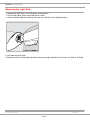
Replacing the Light Bulb
To replace the light bulb in the refrigerator compartment,
1. Pull out the mains plug from the electrical socket.
2. Access the light bulb by removing the cover as indicated in the diagram below.
3. Unscrew the faulty bulb.
4. Replace it with a similar light bulb within the power range indicated on the cover (10 Watt or 15 Watt).
Service Manual UK
English
9 of 17
Indesit Company
Service Manual UK
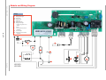
Module and Wiring Diagram
Key:
AC:
LF:
MV:
CO:
PT:
RH:
PR:
10 of 17
Alternating current
Refrigerator light
Motor fan
Compressor
PTC relay
Circuit breaker
Refrigerator light
button/ magnetic reed
switch
S:
Probe
C:
Start condenser (where
installed)
LZ: Freezer light
RC: FZ frame resistor (where
installed)
L1
L4
1234 5
N
L3
1
L2
1234 56 78
3
C
S
PT
CO
RC
AC
LF
RH
PR
L
English
HS2321L
HS2322L
MV
1 2 3
Indesit Company
PROGRAMMING (Using EMIT)
This machine can be programmed via the Emit, using a USB lead (Part number C00222800),
Hardware key (Part number C00115587) and the Memwriter software.
USB - Serial Cable Other types of Cable are available
Black Serial Hardware Key
Replacement pins for the Serial Hardware Key are
available as Part No. C00114723 (Qty = 1)
The Black Hardware Key and USB Serial Cable will be replaced with a new style Hardware Key and
Cable which now has a USB connection. It has shorter, more robust pins, similar to those currently
fitted into the SmartCard Reader. It is not possible to mix old and new cables or keys.
NOTE: - ** The USB Hardware Key also supports a low voltage connection point which allows an
external power supply to be connected to the Hardware Key which enables the main module to be
programmed with a settings file prior to fitting it to an appliance. ** This is NOT applicable to UK
Service Engineers. Do not connect anything to this connection point.
USB Hardware Key - C00289048 & Cable C00289046
USB Cable
C00289046
Low Voltage
Connection Point
(do NOT use)
USB Connection
Service Manual UK
English
11 of 17
Indesit Company
MAIN BOARD PROGRAMMING
NOTE: The module does not have a
physically replaceable EEProm.
Programming a Main Board
There are a number of ways the board
can be programmed - some of which
are not applicable to certain markets.
Smart Card
Reader
Types of programming:
1. Handheld Terminal (Not UK)
2. Emit / Memwriter (UK Indesit
Service Engineers)
3.
Smart Reader and Smart Card
(certain areas of UK market) see
photo.
Smart Card
this card holds the
program file and can
only be used ONCE.
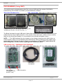
PROGRAMMING (Using Smartcard Reader / Card)
If the Main Module has been replaced during a repair the board will require programming using the following method.
1. Do NOT connect the machine to electrical supply.
2. Insert the pre-programmed card into the Card reader.
Smart Card Reader
Care must be taken at this point to ensure the card is
and Smart Card in use.
inserted correctly with the Chip on the card facing the
This example shows it connected to a
PCB of the Reader.
washing machine module connector
3. Insert the Reader and Card into module connection
port - see photo.
4. Connect the machine to the Electrical supply, the LEDs
on the Smart Card Reader will light in this sequence:
a) Red ON: Good Communication between Smart Card
Reader and Card.
b) Red OFF with Green Blinking: Download taking place.
Do not unplug the appliance or any connections.
c) At end, Green ON ---> Download OK. - Go to 5 below.
d) At end, Red ON or RED Flashing ---> Download NOT
OK.
5. Programming Complete, disconnect the machine from
Electrical supply. Smart will be erased and cannot be
used again.
See page 14 for connection details.
6. Remove the Smart Card Reader.
7. Restart the appliance.
Service Manual UK
English
12 of 17
Indesit Company
Service Manual UK
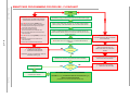
SMARTCARD PROGRAMMING PROCEDURE - FLOWCHART
START
13 of 17
DISCONNECTTHESMARTCARDREADERFROMTHE
APPLIANCEANDTHESMARTCARDFROMTHE
SMARTCARDREADERANDACTIONBELOW:
IftheREDLEDwasflashingSLOWLY,anda
smartcardwasinserted,checkforthefollowing:
x Invalid/erasedsmartcard(previouslyused)
Discardtheinvalidsmartcard,
x Incorrectlyinsertedsmartcard,
(checkorientationofthesmartcardchip)
x Poorconnectionbetweenthesmartcardand
smartcardreader.
IftheREDLEDwasflashingRAPIDLY,checkforthe
following:
x Ensureasmartcardwasinsertedintothe
smartcardreader,
x Ensurethesmartcardwasfullyinserted?
IFTHERED LEDISFLASHING
COMMUNICATIONPROBLEM
SMARTCARDINVALID/ERASED
DISCONNECT(unplug)THEAPPLIANCEFROMTHE
ELECTRICALSUPPLY(grid)
x
x
DISCONNECT(unplug)THEAPPLIANCEFROMTHEELECTRICALSUPPLY(grid)
INSERTAVALIDSMARTCARD,RELATINGTOTHEMODEL&MAINPOWER
MODULE(board)TOBEPROGRAMMED,INTOTHESMARTCARDREADER
INSERTTHESMARTCARDREADERINTOEITHERTHESERIALPORTOFTHE
POWERMODULE(BOARD)ORINTOTHELOWENDADAPTOR(Version2007)
WHERE APPLICABLE
REͲCONNECTTHEAPPLIANCETOTHEELECTRICALSUPPLY(GRID).ASTATIC
REDLEDWILLLIGHTUPTOSIGNALTHATTHESMARTCARDREADERIS
SUPPLIED
NO
DISCONNECTTHESMARTCARDREADER
FROMTHEAPPLIANCEANDTHE
SMARTCARDFROMTHESMARTCARD
READER
ISTHE
GREENLED
FLASHING?
YES
CONNECTIONISVERIFIED(OK)DOWNLOADNOWINPROGRESS
DOWNLOADOK
THESMARTCARDCONTENTWILLBE
AUTOMATICALLYERASED
RESOLVETHEPROBLEM:
FURTHERDIAGNOSTICSMAYBEREQUIRED
ONTHEAPPLIANCE
YES
ISTHE
GREENLED
STATIC?
NO
THEPOWERMODULEISNOWPROGRAMMED.
DISCONNECT(unplug)THEAPPLIANCEFROMTHEELECTRICALSUPPLY(grid)
English
REMOVETHESMARTCARDREADER (DISCONNECTTHELOWENDADAPTORWHEREUSED)
IFTHEDOWNLOADFAILEDTHESMARTCARD
WOULDNOTHAVEBEENERASED
x
IFTHE RED LEDISSTATIC(fixed):
DOWNLOADHASFAILED(KO)
Indesit Company
CONNECTING THE LOW END ADAPTOR - 2007 Version with single and twin cable
IMPORTANT:
1. ALWAYS unplug the appliance from the mains electricity supply when connecting or
disconnecting wiring on the module.
2. ALWAYS connect the smart card reader or Hardware Key to the Low End Adaptor BEFORE
connecting the adaptor to the module PCB connection L4. Ensure correct orientation of the pins.
3. When using the converted Low End Adaptor with the twin cable, ALWAYS insulate the open
end of unused connector block with PVC tape to prevent it coming into contact with any other
items, before connection the mains supply.
The photos below only show the method of connecting the Low End Adaptor (2007) to the module
connection L4. These photos do not show the other wiring connections for the appliance.
When connecting the low end adaptor to the module in the appliance you should temporarily
reassemble the control box and make sure that it is safe before connecting the mains power supply.
Low End Adaptor
Connector
Connection L4
Module
Hardware Key Connection
Smartcard Reader Connection
Unused connector
(see text)
Low End Adaptor
Module
Hardware
Key
These photos show a 2007 Adaptor which has
been converted using C00275571 twin cable.
2007 Adaptors which have not been converted
may also be used to program the module.
Smartcard Reader
To avoid damage to the plastic smartcard
containing the programming file, insert the
smartcard reader into the Low End Adaptor
BEFORE inserting the smartcard.
Note: Smartcards can only be used ONCE.
Service Manual UK
English
14 of 17
Indesit Company
Module Light Sequences - shown for illustrative purposes only
Unprogrammed Module
- with power applied
Temperature
select button
Unprogrammed modules
will have all 5 lights
illuminated.
Note:
Service Modules are
supplied blank and will
require programming.
See Programme.
L1
L2
L3
L4
Low End Adaptor
Connection point L4
Module - Programmed
Programmed modules will
have the middle light
illuminated by default
when powered up after
programming.
Note: Pressing the button
will step through the LED
positions one at a time from
right to left then to the off
position - indicated by 3
beeps and all lights Off.
Further presses will repeat
the sequence.
Module - Controls Side
Shown in the Off state no lights illuminated.
The Off state is achieved
by stepping through all the
temperature options until
all lights are Off.
The compressor will not
run.
An appliance which is
disconnected from the
main supply will also look
like this.
Service Manual UK
English
15 of 17
Indesit Company
INSTALLATION & DOOR REVERSAL
45 min
460
66
in
40
A
KUP 100
676
KM 160 - KUP 141
875
KM 190
1018
KM 230 - KUP 200 1220-1224
540
0
55
in
0m
56
560 min
B
430
B
680
878
1022
1225
55
680 m in
m
45
0m
in
45
n
mi
20
A
40
A
56
220 cm
0m
in
2
min
0
54
5
20
54
220 cm 2
min
ATTENZIONE
WARNING
ATTENTION
20 ÷ 25
08/2009 - 195021555.07
Service Manual UK
English
16 of 17
Indesit Company
Service Manual UK
English
17 of 17


![Maximum Model service Manual.ppt [호환 모드]](http://vs1.manualzilla.com/store/data/006002079_1-f9e925e4876feffe85b493d91263fd66-150x150.png)