1
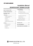
Installation Manual
DOPPLER SONAR
CURRENT INDICATOR
CI-68
SAFETY INSTRUCTIONS .............................................................................................................i
SYSTEM CONFIGURATIONS.....................................................................................................iii
EQUIPMENT LISTS.....................................................................................................................iv
1. INSTALLATION OVERVIEW ................................................................................................1-1
1.1 Selection of Installation Site for Transducer....................................................................1-1
1.2 Ground ............................................................................................................................1-3
1.3 Changing Power Supply Voltage ....................................................................................1-5
2. MOUNTING ...........................................................................................................................2-1
2.1 Monitor Unit/Control Unit.................................................................................................2-1
2.2 Transceiver Unit ..............................................................................................................2-7
2.3 Junction Box (option) ......................................................................................................2-8
2.4 Transducer (Hull Unit) .....................................................................................................2-8
2.5 DC/AC Inverter..............................................................................................................2-12
3. WIRING .................................................................................................................................3-1
3.1 Wiring the Control Unit ....................................................................................................3-1
3.2 Wiring the Transceiver Unit.............................................................................................3-2
3.3 Connecting the Junction Box ..........................................................................................3-4
3.4 External Equipment.........................................................................................................3-6
3.5 DC/AC Inverter................................................................................................................3-8
4. ADJUSTMENTS....................................................................................................................4-1
4.1 [INSTALLATION] menu...................................................................................................4-1
4.2 Input/Output Data............................................................................................................4-8
4.3 External Noise and Interference Check ..........................................................................4-9
4.4 Setting Output Data.......................................................................................................4-12
4.5 DIP Switch Setting ........................................................................................................4-13
4.6 Sea Trial Check.............................................................................................................4-14
PACKING LIST ......................................................................................................................... A-1
OUTLINE DRAWINGS.............................................................................................................. D-1
INTERCONNECTION DIAGRAM ............................................................................................. S-1
www.furuno.com
All brand and product names are trademarks, registered trademarks or service marks of their respective holders.
The paper used in this manual
is elemental chlorine free.
・FURUNO Authorized Distributor/Dealer
9-52 Ashihara-cho,
Nishinomiya, 662-8580, JAPAN
Telephone : +81-(0)798-65-2111
Fax
: +81-(0)798-65-4200
All rights reserved.
Printed in Japan
A : NOV . 2003
C : NOV . 15, 2011
Pub. No. IME-72520-C
(AKMU )
CI-68
*00014802412*
*00014802412*
* 0 0 0 1 4 8 0 2 4 1 2 *
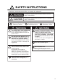
SAFETY INSTRUCTIONS
Read these safety instructions before you operate the equipment.
WARNING
Indicates a condition that can cause death or serious
injury if not avoided.
CAUTION
Indicates a condition that can cause minor or moderate
injury if not avoided.
Warning, Caution
Prohibitive Action
WARNING
Turn off the power at the switchboard
before beginning the installation.
Fire or electrical shock can result if the
power is left on.
Do not install the display unit or
transceiver unit where it may get
wet from rain or water splash.
Water in the equipment can result in
fire, electrical shock or damage the
equipment.
Do not open the cover unless totally
familiar with electrical circuits and
service manual.
High voltage exists inside the
equipment, and a residual charge
remains in capacitors several minutes
after the power is turned off. Improper
handling can result in electrical shock.
Mandatory Action
WARNING
Install the specified transducer tank in
accordance with the installation instructions. If a different tank is to be
installed the shipyard is solely responsible for its installation, and it should
be installed so the tank doesn't strike
an object.
The tank or hull may be damaged if the
tank strikes an object.
The mounting location must be away
from rain and water splash.
Use the proper fuse.
Use of a wrong fuse can result in
damage to the equipment or cause fire.
The transceiver unit weights 17 kg.
Reinforce the mounting area, if
necessary.
i
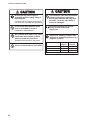
SAFETY INSTRUCTIONS
CAUTION
CAUTION
Be sure that the power supply is
compatible with the voltage rating of
the equipment.
Connection of an incorrect power supply
can cause fire or damage the equipment.
The transducer cable must be handled
carefully, following the guidelines
below. Keep fuels and oils away from
the cable. Locate the cable where it
will not be damaged.
Do not install the transducer where
noise or air bubbles is present.
Performance will be affected.
Ground the equipment to prevent
electrical shock and mutual
interference.
Do not allow warm water or any other
liquid other than seawater or freshwater to contact the transducer.
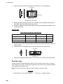
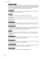
Observe the following compass safe
distances to prevent intereference to a
magnetic compass:
Damage to the transducer may result.
Power on the transducer in the water.
ii
Transceiver unit
Control unit
Monitor unit
Standard
compass
2.00m
0.30m
0.80m
Steering
compass
1.30m
0.30m
0.55m
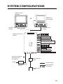
SYSTEM CONFIGURATIONS
MONITOR UNIT
MU-100C
VGA Monitor
(Local supply)
OR
CURRENT INDICATOR
CURRENT INDICATOR
LYR1
-
LYR1
+
LYR5
F1
-
+
LYR4
LYR4
POWER
POWER
LYR3
LYR2
TRACK
MODE
LYR2
RANGE
DISP
MODE
BRILL
MENU
F1
LYR3
CONTROL UNIT
CI-6888
RANGE
CONTROL UNIT
CI-6888
NMEA1 Output
TRANSCEIVER UNIT
CI-6810
NMEA1 Input
NMEA2/CIF Output
NMEA2/CIF Input
Current Indicator Data
AUX (NMEA/CIF/Current Indicator
Data/Data for Display)
Heading Sensor
Alert / Alram
Speed Log (2 lines)
KP Output
KP Input (2 lines)
Power ON/OFF Status (Contact signal)
100/110/115-120/200/
220/230/240 VAC
1φ, 50-60Hz
JUNCTION BOX
CI-630
24 VDC
: Standard Supply
DC-AC INVERTER
TR-2451
: Optional Supply
: Local Supply
TRANSDUCER
CI-620
iii
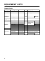
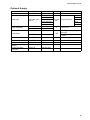
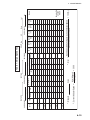
EQIUIPMENT LISTS
Standard Supply
Name
Control/Monitor
Unit
Control Unit
Transceiver
Unit
Transducer
Transducer
Casing
Thru-Hull Pipe
Installation
Materials
Accessories
Spare Parts
iv
Type
CI-6888/MU-100C
Code No.
-
Qty
Remarks
w/display unit
1 set
CI-6888
CI-6810
-
no display unit
CI-620-1-68
CI-620-2-68
CI-620-T-F
-
CI-620-K-F
CP66-01600
CP66-01610
CP66-01620
CP66-01630
CP66-01501
CP66-01504
CP66-01503
FP02-05100
SP66-00801
000-070-017
000-070-018
000-070-019
000-070-020
006-917-660
006-917-350
006-916-750
000-012-474
006-916-730
SP66-00800
000-070-002
1
SP66-00802
SP66-00803
006-917-330
006-917-340
1
1
1 set
w/10 m cable
w/20 m cable
Select one.
1
1
Choose
one.
1
1
1
1
1
10 m
20 m
30 m
50 m
For transducer unit
For transceiver unit
For display unit
FP06-01102, FP02-05101
For control unit
For control/monitor unit,
w/SP06-01101, SP66-00801
For 100 VAC
For transceiver unit
For 200 VAC
Between transceiver and control units
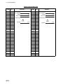
EQIUIPMENT LISTS
Optional Supply
Name
Junction Box
Cable (4P)
Cable Assembly
Accessories
Transducer Casing
Thru-Hull Pipe
DC-AC Inverter
Multi-Purpose LCD
Display
Control unit flush
mount kit
Type
CI-630
66S1239*5M*
66S1239*10M*
FP06-01120
Code No.
000-146-086
000-146-087
000-146-088
000-146-089
000-146-090
000-148-493
000-148-498
006-556-260
FP66-00601
006-916-680
CI-620-T-S
CI-620-K-S
TR-2451
MU-100C
-
Z-6FVNV-SX-C
3P+1P
OP06-18
006-556-320
Qty
1 set
Remarks
w/CP66-00703
5m
10 m
Choose
For junction box
15 m
one.
20 m
30 m
Between display unit and
1
control unit
1 set
1 set
1 set
1 set
1 set
For fixing control unit,
Box type
For fixing control unit,
V-type
For steel ship
For steel ship
1
v
EQIUIPMENT LISTS
This page is intentionally left blank.
vi
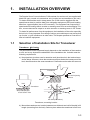
1.
INSTALLATION OVERVIEW
The Doppler Sonar Current Indicator CI-68 consists of a monitor unit (not supplied with
black box type), control unit, transceiver unit, junction box and transducer (hull unit).
To obtain absolute tide even in deep waters, the CI-68 must be supplied with the
speed/course data (or position data) from navigation equipment (GPS) and heading
data from a gyrocompass (via an A-D converter). The equipment can output ship’s
speed and true bearing data to a radar or scanning sonar for true-motion display. Further, current data can be output to an echo sounder or scanning sonar in CIF format.
To obtain full performance from the equipment, the installation of the units, especially
the hull unit, is very important. Poor siting of units or poor cable layout may cause pickup of noise, or give interference to other units. This chapter presents an overview of
how to install the equipment.
1.1
Selection of Installation Site for Transducer
Transducer(Hull tank)
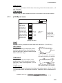
The performance of the equipment largely depends on the installation of the transducer unit, and a very important consideration is the installation site. It should meet the
following requirements.
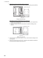
a) No projections (such as sonar’s retraction tank) should exist in the hatched area
shown below. However, when the transducer projects below the lowest part of the
keel, the effects when the sonar transducer is lowered must be taken into account.
Transducer
Bow
Hull Unit Projecting
Distance
45°
Keel
Keel
80°
Transducer
50°
Bow
Cross Section view
50°
80°
Hull Unit (Transducer)
Transducer, mounting location
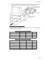
b) Mount the transducer at a location between one-third and one-half of the ship’s full
length (measuring from the bow). Select a place where the transducer is free from
1-1
1. INSTALLATION OVERVIEW
the effects of air bubbles. The transducer face should not be above the sea surface
when the ship is pitching or rolling.
c) In general, the air bubbles produced at the bow flow backward alongside the keel.
Therefore, separate the transducer by more than 1000 mm from the keel, or flush
mount the transducer inside the keel.
d) The surface of the transducer should project by 250 mm or more from the hull bottom. For better performance, its surface should be even with the keel’s lowest point
or below it.
e) The following is important for preventing interference between the CI-68 and other
equipment. If the transducer of an echo sounder or scanning sonar whose harmonic is within the frequency range of 236 kHz to 252 kHz (244±8 kHz) is mounted,
interference may occur. Even if the harmonic is out of the range, the risk of interference still exists if the transducer of the CI-68 and other equipment are mounted
near one another. For this reason, separate the transducer of the CI-68 as far as
practical from other equipment which have high output power. If interference is unavoidable due to limited mounting space, connect the interfering equipment to the
built-in interference rejection circuit (two inputs) in the transceiver unit. For connection to this circuit, you will need to run a two-cores cable between it and the interfering equipment.
f) Make the transducer cable as short as possible. The cable is generally installed in
grounded steel conduit run between the transducer and the junction box, to prevent pick-up of noise. The transducer with the 20 m transducer cable can be used
only when it is passed inside conduit.
NOTE
Do not transport the transducer by pulling the
transducer cable.
The internal wiring may be cut.
WARNING
Install the specified transducer tank in accordance
with the installation instructions. If a different tank
is to be installed the shipyard is solely responsible
for its installation, and it should be installed so the
hull will not be damaged if the tank strikes an
object.
The tank or hull may be damaged if the tank strikes an
object.
If a steel tank is installed on an FRP vessel, take
appropriate measurements to prevent electrolytic
corrosion.
Electrolytic corrosion can damage the hull.
1-2
1. INSTALLATION OVERVIEW
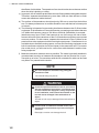
1.2
Ground
This equipment uses pulse signals which may cause interference to other electronic
equipment such as a direction finder and radio receiver, if it is not grounded properly.
It is strongly recommended to ground all cables referring to the guidelines below.
a) Separate all units as far as possible from radio equipment.
b) Do not run interconnection cables close to or near radio equipment or its cables.
c) Run the cables in the shortest path practical.
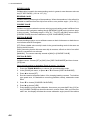
d) Lay the cables on grounded copper plate and fix them every 300 mm with metal
cable clamps.
e) Ground all units as shown in the figure below and on the next page.
f) To join copper straps, use solder cream for perfect contact.
Copper plate for main ground
(Ground to theship’ s body every
80 cm.)
To join the copper straps,use
solder cream or silversolder for
perfect contact.
Scrape off paint; groundthe armor
with a metal cableclamp.
Example of ground
Location of earth terminal on each unit and grounding method
CAUTION
Ground the equipment.
Ungrounded equipment can give off or receive
electromagnetic interference or cause electrical shock.
1-3
1. INSTALLATION OVERVIEW
Monitor unit/Control unit
Fix the ground wiresby
the two wing nutsat the
rear of the units.
Transceiver unit
This protection earth should be grounded securely.
Fix copper strap (w=50 mm)to ground
studs by the two wing nuts.
Junction box
Note: Ignore the protection
grounding label at the fixing
location for the copper strap.
Fix copper strap to groundstuds by the two wing
nuts.
Location of ground terminals
1-4
1. INSTALLATION OVERVIEW
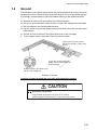
1.3
Changing Power Supply Voltage
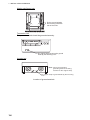
1φ, 50/60 Hz AC power is supplied to the transceiver unit. The transformer tap is set
at the factory according to customer’s order. If necessary, change jumper wires at the
terminal board of the transceiver unit according to the input voltage.
WARNING
Turn off the power at the power supply before
opening the cover.
Fire or electrical shock can result if the power is left
on.
Use the correct fuse.
Use of wrong fuse can result in damage to the
equipment.
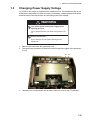
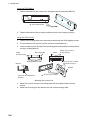
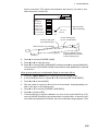
1. Remove the cover from the transceiver unit.
2. Disconnect the connectors J5 and J8 from the board at the upper of the transceiver unit.
J8
J5
3. Unfasten four screws shown with arrows in above to remove the PTX6 Board.
1-5
1. INSTALLATION OVERVIEW
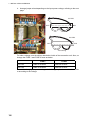
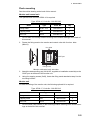
4. Arrange jumper wires depending on the input power voltage, referring to the next
page.
100 VDC
WHT
C 120V 110V 100V 0V 120V 110V 100V 0V
BLK
200 VDC
WHT
C 120V 110V 100V 0V 120V 110V 100V 0V
BLK
Trans wiring
For other voltages, see the sticker attached at inside of the transceiver unit. Also, exchange the FUSE 1 and FUSE 2 fuses as below.
FUSE1
FUSE2
100 VAC
FGBO 5A AC250V
FGBO 5A AC250V
200 VAC
FGBO 3A AC250V
FGBO 3A AC250V
Note: After changing the power voltage, check the appropriate box on the above sticker according to the voltage.
1-6
2.
MOUNTING
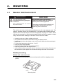
2.1
Monitor Unit/Control Unit
WARNING
NOTICE
Turn off the power at the
switchboard before beginning the
installation.
Fire or electrical shock can result if
the power is left on.
Do not apply paint, anti-corrosive
sealant or contact spray to coating or
plastic parts of the equipment.
Those items contain organic solvents that
can damage coating and plastic parts,
especially plastic connectors.
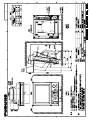
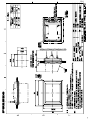
The monitor and control units can be installed as one unit or two separate units. The
optional “separate monitor unit installation kit” is necessary when installing them as
separate units. See "Mounting the control unit separately" on page 2-3. Further, these
units can be mounted in a panel (requires optional flush mount kit), together or separately. See the outline drawings at the back of this manual for details.
• Locate the units out of direct sunlight and hot air.
• The operator should face the bow while viewing the display screen.
• Select a location where the display screen can be easily observed while operating the
control unit.
• Environmental temperature should be -15 to 55°.
• Select the place well-ventilated.
• Locate the units at the place with minimal vibration.
• Keep the unit away from the magnetic field.
• Leave sufficient space around the units for maintenance and servicing. Recommended maintenance space appears in the outline drawing at the back of this manual.
Desktop mounting
Monitor unit and control unit
1. Fasten the mounting base to the mounting location with four tapping screws
(5x20).
Front
Mounting base
2-1
2. MOUNTING
2. Mounting the monitor unit together with the control unit
Fasten the hanger at the rear of the monitor unit with four binding screws (M4x10).
Bracket (rear view)
1
2
1
2
3
4
3
4
CONT port
Hanger (landscape-type)
Mounting the monitor unit separately from the control unit
1) Dismount the coupling plate from the rear of the monitor unit to separate the
monitor unit from control unit.
2) Attach the hanger at the rear of the monitor unit with four binding screws
(M4x10).
Bracket (rear view)
1
1
3
2
2
4
3
4
CONT port
Monitor unit, rear view
3. Grease threads of upset screws (M6x16, 2 pcs.) used to fasten the hanger to the
mounting base.
4. Attach the waterproofing cap (MJ-A10C, supplied as the installation materials) to
the CONT port at the back of the monitor unit.
2-2
2. MOUNTING
5. Fasten the hanger (or monitor unit) to the mounting base with two upset screws.
(Use the upper holes to tilt the monitor unit 20°; lower holes to tilt it 9°.)
Use these holes to
tiltmonitor unit 20°.
Mounting base
Use these holes to tilt
monitor unit 9°.
Bracket
Upset screw
Mounting the control unit separately
To mount the control unit separately or without the monitor unit, one of the following
accessories (option) is required.
Type: FP66-00601, Code No.: 006-916-680
Name
Type
Code No.
Qty
Bracket
66-030-3021
100-307-800
1
Tapping screw
4x16 SUS304
000-802-080
4
Pan head screw
M4x10 C2700W
000-881-964
2
Type: FP06-01120, Code No.: 006-556-260
Name
Type
Code No.
Qty
Mounting plate
06-021-2111
100-279-740
1
Bracket
06-021-2112
100-281-880
1
Tapping screw
5x20
000-802-081
2
Hex. screw
M4x12
000-882-040
4
Hole plug
DP-687
000-808-417
2
2-3
2. MOUNTING
Using the FP66-00601
1. Fasten the bracket to the control unit, using two pan head screws (M4x10).
: Pan head screws
2. Fasten the bracket to the mounting location with four 4x16 tapping screws.
Using the FP06-01120
1. Fasten the mounting plate to the mounting location with two 5x20 tapping screws.
2. Fix the bracket to the control unit with two hex. screws (M4x12).
3. Insert screwdriver from the top of the mounting plate holes and then loosely fasten
two hex. screws (M4x12).
Mounting plate
Cable
entarance hole
Cable
Fasten the screws to
fix the bracket.
Set to the hex. screws
tightened at step 3.
Tapping screws (5x20)
Bracket
Bracket
Cable can be passed this
direction.
: Fix with hex. screws.
Mounting the control unit
4. Attach the control unit to the mounting plate and then tightly fasten two hex.
screws.
5. Attach two hole plugs to the holes at the top of the mounting plate.
2-4
2. MOUNTING
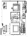
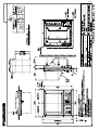
Flush mounting
See the outline drawing at the back of this manual.
Monitor unit/control unit
The optional flush mount kit OP06-16 is required.
Type: OP06-16, Code No.: 006-556-300
Name
Type
Code. No.
Qty
Fixing metal
06-021-1311
100-279-611
1
Tapping screw
5x20
000-802-840
6
Hex. bolt
M4x12
000-882-040
4
1. Cut out hole in mounting location referring to the outline drawings at the back of
this manual.
2. Fasten the fixing metal to the monitor and control units with four hex. bolts
(M4x12).
Hex bolts
CONT port
Fixing metal
Monitor unit/control unit, rear view
3. Attach the waterproofing cap (MJ-A10C, supplied as installation materials) to the
CONT port at the back of the monitor unit.
4. Using four tapping screws (5x20), fasten the fixing metal attached at step 2 to the
mounting location.
Monitor unit
For flush mounting of the monitor unit, the following optional kit is required.
Type: OP06-17, Code No.: 006-556-310
Name
Type
Code No.
Qty
Fixing metal
06-021-1321
100-279-622
1
Tapping screw
5x20
000-802-840
4
Hex. bolt
M4x12
000-882-040
4
1. Cut out a hole (H207xW287) in the mounting location referring to the outline drawings at the back of this manual.
2-5
2. MOUNTING
2. Fasten the fixing metal to the monitor unit with four hex. bolts (M4x12).
Hex. bolts
CONT port
Fixing metal
Monitor unit, rear view
3. Attach the waterproofing cap (MJ-10C, supplied as the installation materials) to
the CONT port at the back of the monitor unit.
4. Using four tapping screws (5x20), fasten the fixing metal attached at step 2 to the
mounting location.
Control unit
Type: OP06-18, Code No.: 006-556-320
Name
Type
Code No.
Qty
Fixing metal
06-021-2101
100-279-731
1
Tapping screw
5x20
000-802-840
4
Hex. bolt
M4x12
000-882-040
2
1. Cut out a hole in the mounting location referring to the outline drawings at the back
of this manual.
2. Fasten two hex. bolts (M4x12) to fix the fixing metal to the control unit.
Hex. bolts
Fixing metal
3. Fasten four tapping screws (5x20) to fix the control unit to the mounting location.
Blackbox type
Supply monitor and interconnection cable (D-sub connector, three rows of 15 pins,
max. length 15 m) locally. The monitor connects to the control unit, and should satisfy
the specifications shown below.
Note: The D-sub connector with two rows of 15 pins cannot be used.
VGA type
• Analog RGB, 0.7 Vpp, positive polarity • TLL level H, V, negative polarity
2-6
2. MOUNTING
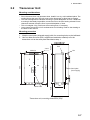
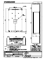
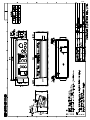
Transceiver Unit
Mounting considerations
• Since the transceiver unit generates heat, install it in a dry, well-ventilated place. The
cooling fans at the top of the unit must not be obstructed, to allow heat to escape.
• This unit is designed for bulkhead mounting to permit dissipation of heat. If bulkhead
mounting is absolutely impossible, mount the unit on the floor leaving at least 50 mm
clearance between it and the floor to permit dissipation of heat.
• This unit weights 19 kg. Reinforce the mounting area, if necessary.
• Leave space around the unit for maintenance and checking. Refer to the drawing at
the back of this manual.
Mounting procedure
1. Weld the steel plate (shipyard supply) with four mounting holes to the bulkhead.
4-Ø12
#200
2. Use four bolts and nuts (M10, supplied as installation material) to fix the
transceiver unit to the steel plate described at step 1.
Bolt
280±0.5
530
566±0.5
Nut
12
590
Name Plate
Steel plate
(local supply)
160
#250
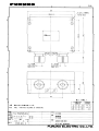
2.2
Transceiver unit, mounting dimensions (mm)
2-7
2. MOUNTING
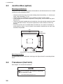
2.3
Junction Box (option)
Mounting considerations
The junction box forms a joint between the transducer and the transceiver unit. Install
it referring to the guidelines below.
• Keep the junction box away from noise-emitting electrical machinery, i.e., electric generator, radio transmitter, TV, etc.
• Although the box is splashproof, do not install it in places of high humidity.
• Avoid installing the box where temperature varies greatly, since moisture may penetrate the box.
• The box is generally installed above the draft line of the ship and the transducer cable
is run inside steel conduit. This permits replacement of the transducer without dry
docking.
• Even if the junction box is installed below the draft line, the conduit is necessary to
avoid picking up noise. If use of conduit is not possible, install the box as near to the
transducer as possible.
200
43
160
4-Ø6.5
Fixing Holes
140
180
Junction box, mounting dimensions (mm)
Mounting procedure
Fix the junction box to a bulkhead, referring to the figure above for mounting dimensions.
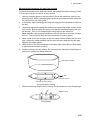
2.4
Transducer (Hull Unit)
See chapter 1 to mount the transducer.
NOTE
Do not transport the transducer by pulling
the transducer cable.
The internal wiring may be cut.
2-8
2. MOUNTING
Mounting the transducer for steel hull vessels
To mount the transducer for steel hull vessels, the optional transducer casing (CI-620T-S) and thru-hull pipe (CI-620-K-S) are required.
1. Select a mounting place on the hull bottom. (Since the transducer cable is comparatively thick, select a mounting place for the thru-hull pipe where the cable can
be easily led into the cable gland.)
2. If necessary, weld a doubling plate (shipyard supply) to the hull bottom to reinforce
the hull.
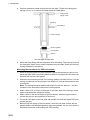
3. Unpack the transducer casing and determine the projecting length, making it 250
mm or more. Before cutting the casing, note that the transducer casing has foreaft direction. Then, cut it considering the rising angle of the ship's hull.
Note: Weld the casing in parallel with ship's fore-aft line with an accuracy of better
than ±1°. The transducer face should be horizontal at cruising speed.
4. Make a hole for the thru-hull pipe in the hull bottom. Before welding the thru-hull
pipe, remove the rubber packing from the thru-hull pipe. Weld the thru-hull pipe.
Replace the rubber gasket.
5. Make a hole of 10 to 20 mm diameter on the stern side of the casing to allow water
to penetrate the transducer casing.
6. Weld the casing to the hull bottom. Do not remove the transducer fixing flange to
prevent the casing from being deformed.
Transducer casing
Bow
Dimple to bow
Transducer fixing flange
Fixing transducer casing
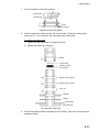
7. Dismount the fixing flange from the casing. Fix the transducer to the fixing flange.
Nipple to bow
Fixing flange
2-9
2. MOUNTING
8. Pass the transducer cable through the thru-hull pipe. Tighten the cable gland,
leaving 0.5 to 1 m of slack in the cable below the cable gland.
Flange with
piping holes
Welding
Hull bottom
Thru-hull pipe
Rubber gasket
Flat washer
Gland
Thru-hull pipe for steel hull
9. Mount the fixing flange with the transducer onto the casing. Take care not to pinch
the transducer cable. Never hold the transducer by the cable. Shock will most assuredly damage the transducer.
Mounting the transducer for FRP hull vessels
1. Select a mounting place on the hull bottom. (Since the transducer cable is comparatively thick, select a mounting place for the thru-hull pipe where the cable can
be easily led into the cable gland.)
2. Determine the projecting length of the casing, making it at least 250 mm. Cut the
casing, considering the rising angle of the ship's hull, so that the transducer face
is horizontal.
Note: The casing should be parallel with ship's fore-aft line within ±1°, and the
transducer face should be horizontal at cruising speed.
3. Make a hole of 10 to 20 mm in diameter on the stern side of the casing to allow
water to penetrate the transducer casing.
4. Make a hole for the thru-hull pipe on the hull bottom. Allow enough clearance
around the pipe for easy tightening of lock nuts.
5. Fix the thru-hull pipe on the hull plate with double nuts and then apply FRP glue
around the pipe.
6. Before fixing the casing to the hull bottom, clean the hull plate surface with an
electric sander until fiberglass appears, then remove dusts, oils, etc. from surface.
Reinforce both sides of the casing with FRP molding.
2-10
2. MOUNTING
7. Fix the transducer to the fixing flange.
Fixing plate
Transducer
Dimple to bow
Transducer and fixing flange
8. Pass the transducer cable through the thru-hull pipe. Tighten the cable gland,
leaving 0.5 to 1.0 m of slack in the cable below the cable gland.
To tighten the cable gland
1) Tighten the gland securely by using the wrench.
2) Tighten the double nut securely.
Gland
Flat washer
Rubber gasket
Flat washer
Double nut for gland
Double nut for gland
Lock nut
Washer
Gasket
Hull bottom
Thru-hull pipe
Thru-hull pipe, side view
9. Fix the fixing flange with the transducer to the casing. Take care not to pinch the
transducer cable.
2-11
2. MOUNTING
2.5
DC/AC Inverter
If the power supply is 24 VDC, the DC-AC inverter is required. This unit is designed
for the bulkhead mounting and weights 15 kg, reinforce the mounting location if necessary. The cable entrances must be faced downward.
Note: Mount this unit in a well-ventilated place to prevent heat build up inside the cabinet.
53
105
105
75
6-Ø9
Fixing
hole
285
DC-AC inverter, mounting dimensions (mm)
2-12
3.
WIRING
See the interconnection diagram at the back of this manual.
3.1
Wiring the Control Unit
3.1.1
Connection with the transceiver unit
Attach the connector of the control unit to the cable (66S1238) from the transceiver
unit as below.
To J11 on the
PCP Board
66P3920
Cable 66S1238
10/20/30/50 m
Transceiver unit
Control unit
3.1.2
Connection with the monitor unit
Choose one from the follows to connect the control unit and monitor unit (VGA monitor).
VGA
㫄㫆㫅㫀㫋㫆㫉
Cable
66S1239
0.3 m
Control/monitor units
Monitor unit
Control unit
Cable
66S1239
5 m or 10 m
(option)
Control unit
User
supply
Cable
66S1242
0.3 m
3-1
3. WIRING
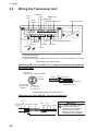
3.2
Wiring the Transceiver Unit
LOG-ALM
Gyro
input
CID
NMEA1 RX
NMEA2 RX
NMEA2 NMEA1 TX
TX
Gyro
output
TB3䈻
Transducer cable
TB1䈻
TB4䈻
TB4䈻
*3
TB2䈻
KP. OUT
AUXTX*2 Control unit cable (66S1238)
LOG200_2
LOG200_1
KP.IN2 ON_OFF*1
Power cable
KP. IN1
*1: Contact alarm signal
*2: CIF/NMEA/Current
*3: When connecting the cable from the junction box, reverse the direction of the clam
Transceiver unit, bottom view
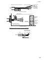
Fabricating DPYC-2.5 and DPYCY-2.5 (Japanese Industrial Standards) or
equivalent cable
DPYC-2.5
(DPYCY-2.5: w/outer sheath)
Armor
Armor
20
Vinyl tape
Sheath
65
30
Ø = 12.8 mm
(DPYCY-2.5: Conductor 2
S = 2.5 mm
14.8 mm)
Ø = 2.01 mm
7
FV5.5-S4
Dimensions: mm
Power cable DPYC-2.5 or DPYCY-2.5
Fabricating 4P cable (66S1067, from the junction box)
Armor
Anticorrosive
sheath
Vinyl sheath
30
3-2
5
Shield
Red
Blue
Green Black Shield
130
NOTE
Carefully connect the wires
to respective terminals,
referring to the illustrations
and the interconnection
diagram. Wrong connection
can damage the transducer.
3. WIRING
Remove the sheath.
Fold back the shield on the armor.
FV1.25-4
Vinyl tube
Anticorrosive
sheath
35 mm
25 mm
Transducer cable 1
Earth terminal
Connect the crimp-on lug of the shield wire here.
1
3
5
7
Temperature 9
sensor, Blue 11
13
Lay armor in cable
clamp to ground cable.
2 BEAM1
4 Black
6
8
BEAM2
10 Red
12 BEAM3
14 Green
Transducer cable 2
Fabricating of the control unit cable (66S1238)
Cut off the internal
shield and sheath.
Vinyl tape
8 to 9
Armor
66S1238
30
50
150
3-3
3. WIRING
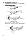
3.3
Connecting the Junction Box
The transducer cable is connected to the junction box with an extension cable. After
making the connection, seal the cable gland with putty for watertightness.
Transducer cable (66S1066, no armor)
Vinyl sheath
Cut to suitable length considering location on terminal board.
FV1.25-4
*
*
*
*
FV2-P4
Insulation tube
Rubber gasket
FV5.5-5
Junction box
Gland
Vinyl tape
See interconnection
diagram.
Vinyl tape
To internal earth stud
Transducer cable (no armor)
4P pair cable (66S1067, extension cable, with armor)
Attach crimp-on lugs in the same manner as shown above. Fabricate the armor as follows.
Anticorrosive
sheath
Armor
Clamp vinyl sheath by cable gland.
Solder vinyl wire.
Rubber gasket
Gland
To earth terminal (Wing nut)
4P cable (w/armor)
3-4
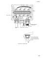
3. WIRING
BLK
Shield
*
*
BLK
RED
GRN
*
*
RED
BLU
Outer shield
*
BLK
*
*
*
RED GRN BLU
Clamp vinyl sheath
by cable gland.
Armor
Transducer
cable
Copper strap
4P cable
After clamping cable,
seal cable gland with
putty for watertightness.
Vinyl tape
Junction box, inside view
3-5
3. WIRING
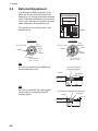
3.4
External Equipment
A gyrocompass, NMEA equipment, LOG
pulse and KP signal are connected to the
transceiver unit. Use the connectors attached
to the PCN Board (66P3924) in the transceiver unit. Also, the opener is supplied as installation materials for the transceiver unit.
66P3926(PPW8)
66P3923(PTX8)
66P3920(PCP)
The right figure is the internal view of the
transceiver unit.
1
1
8
1
13
TB3
1
TB1
1
TB4
2
66P3921(PTR8)
Opener
1
12
10
4 3
10
TB2 J11
66P3924(PCN)
TTYCY-4S
TTYCYS-1
Ø = 12.1 mm
Shield
Vinyl
Sheath
Armor
Vinyl
Sheath
Ø = 21.1 mm
Armor
Shield
Vinyl
Sheath
Vinyl
Sheath
Conductor
S = 0.75 mm2
Ø= 1.11 mm
Conductor
S = 0.75 mm2
Ø= 1.11 mm
TB1
Use TB1 to transmit/receive NMEA and
current indicator’s signal.
Cut off the internal
shield and sheath.
Armor
Vinyl tape
8 to 9
TTYCYS-1
30
50
TB2
Use TB2 to output RS-422 (ship’s speed,
current data etc.) and power ON/OFF
(contact signal).
250
Cut off the internal shield and sheath.
Vinyl tape
Armor
8 to 9
TTYCYS-1
30
50
3-6
150
3. WIRING
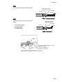
TB3
Use TB3 to input/output GYRO signal.
Cut off the internal
shield and sheath.
Vinyl tape
Armor
8 to 9
TTYCY-4S
30
TB4
50
Use TB4 to input/output the following
signal.
•
•
•
•
Cut off the internal
shield and sheath.
Vinyl tape
Armor
Alarm signal Output
Log signal Output
KP signal Input
KP signal Output
280
8 to 9
TTYCYS-1
30
50
Opener
200
1. Attach the opener to the connector.
2. Push the opener.
3. Insert the cable core.
4. Release the opener.
How to attach cable core to the connector
3-7
3. WIRING
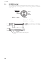
3.5
DC/AC Inverter
Use the DPYCY-6 (Japanese Industrial Standards) cable to connect the DC-AC inverter from the ship’s power supply within 5 m. For outputting 100VAC, use the DPYCY-2.5 cable.
DPYCY-2.5/6
Armor
Vinyl
Sheath
Ø = DPYCY-2.5: 11.7 mm
DPYCY-6: 15.2 mm
Vinyl
Sheath
Conductor
(DPYCY-2.5)
(DPYCY-6)
S = 6 mm
Ø = 3.12 mm
S = 2.5 mm
Ø = 2.01 mm
FV5.5-6 (DC input: Local supply)
FV5.5-4 (AC output: Local supply)
10
80
8
Vinyl tape
Fasten the armor to the cable gland.
3-8
4.
ADJUSTMENTS
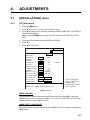
4.1
[INSTALLATION] menu
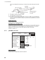
4.1.1
[I/O] sub menu
1. Press the MENU key.
2. Press S to move the cursor to the top of the menu.
3. Press X several times to show the message "PRESS FUNC KEY TO OPEN INSTALLATION MENU."
Note: Press the MENU key to open the menu other than the INSTALLATION
menu.
4. Press the F1 key and then select [INSTALLATION].
5. Press T.
6. Press W to select [I/O].
MENU 1
MENU 2
ALARM
INSTALLATION
I/O CALIB OTHER
NMEA VERSION
NMEA PORT 1
BAUD RATE
NMEA2/CIF
FORMAT
NAV SOURCE
:
1.5
:
4800
38400
:
:
NMEA
AUTO
CIF
GPS
NAV DATA
:
TIME INTERVAL* :
HEADING DEVICE :
FORMAT**
:
HDG OUT > 0.5kn :
HDG OUT < 0.5kn :
LOG PULSE MODE :
LOG PULSE OUT :
TIDE OUT INT
:
TEMP SENSOR
:
2.0
3.0
IEC61162
SPD
L/L
1 min
NO
YES
AD-10
NMEA
COG HEADING
COG HEADING
GT/WT
WT
FORE FORE/AFT
15 sec
NO
YES
MENU ON INSTALLATION SETTINGS.
[/]:SELECT, [/]: CHANGE, [MENU]: EXIT
LORAN-C
* Shown when [NAV
DATA] is set to [L/L].
** Shown when
[HEADING DEVICE]
is set to [YES].
[I/O] sub menu
NMEA VERSION
Choose NMEA version of sentences which are output from the NMEA 1 port and
NMEA2/CIF port. The choices are NMEA 1.5, 2.0 and 3.0, and IEC61162. The input
sentences do not require NMEA version.
NMEA PORT 1 BAUD RATE
Choose baud rate of equipment connected to NMEA 1 port. The choices are 4800 and
38400 (bps).
4-1
4. ADJUSTMENTS
NMEA2/CIF FORMAT
Choose format of equipment connected to NMEA2/CIF port. The choices are [NMEA]
and [CIF]. When selecting [NMEA] here, the sentences are output with the NMEA version selected at [NMEA VERSION]. The baud rate is fixed to 4800 bps. To choose
CIF, set the jumper switch J4 on the PCN Board (66P3924) to CIF.
NAV SOURCE
Choose source of nav data among [AUTO], [GPS] and [LORAN-C]. [AUTO] reads position data in order of accuracy: GPS>LC.
NAV DATA
Choose source data for calculation of sea tide in the NAV mode.
[SPD]: Speed data from the GPS navigator is used as ground tracking speed to calculate sea tide.
[L/L]: Position data from the GPS navigator is used as ground tracking speed to calculate sea tide.
TIME INTERVAL
Set the time interval for reading position data to use for calculating speed. Effective
when [NAV DATA] above is selected to [L/L]. The choices are 1, 2, 3 and 4 (min).
HEADING DEVICE
Choose [YES] if a heading device is connected to the current indicator. When [YES]
is selected, you can choose [HEAD UP] or [NORTH UP] on the [DISP1] sub menu. For
selection of [NO], the display mode is fixed to [HEAD UP].
FORMAT
When [YES] is selected at [HEADING DEVICE] above, choose the format of the
heading device which is connected to the current indicator. The choices are [AD-10]
and [NMEA].
HDG OUT >0.5kn
Choose type of bearing to output when ship’s speed is higher than 0.5 kn. The choices
are [COG] (Course Over Ground) and [HEADING].
HDG OUT <0.5kn
Choose type of bearing to output when ship’s speed is lower than 0.5 kn. The choices
are [COG] (Course Over Ground) and [HEADING].
LOG PULSE MODE
Choose the tracking mode to use as source for the log pulse. The choices are [GT/
WT] (ground tracking/water tracking) and [WT] (water tracking).
LOG PULSE OUT
Output log pulse in fore direction or both fore and aft directions.
4-2
4. ADJUSTMENTS
TIDE OUT INT
Choose the output interval for tide data, from among 15 and 30 seconds, and 1, 2, 5
and 10 minutes.
TEMP SENSOR
Choose [YES] if a water temperature sensor is connected to the current indicator.
4.1.2
[CALIB] sub menu
MENU 1
MENU 2
ALARM
INSTALLATION
I/O CALIB OTHER
DRAFT
:
0.0m
HEEL ANGLE
TRIM ANGLE
:
:
0.0°
0.0°
GT SPD CALIB
WT SPD CALIB
:
:
0.0%
0.0%
BEARING CALIB
COURSE CALIB
:
:
0.0°
0.0° (GT: 0.0°
CSE CALIB MODE :
GT
NAV
CSE CALIB EXEC* :
SOUND VELOCITY :
EXTERNAL KP1
:
NO
NO
0.0m
YES
YES
EXTERNAL KP2
0.0m
:
NAV: 0.0°)
MANUAL
* Shown when
[CSE CALIB
MODE] is set to
[GT] or [NAV].
[CALIB] sub menu
DRAFT
Set ship’s draft to get depth from draft rather than transducer. (-5 to 25.5 (m))
HEEL ANGLE
Compensate lateral (port-starboard) inclination of the transducer face. Set [+] angle for
port-high state and [-] angle for starboard-high
state. (-12.8 to 12.7 (°))
Port
Starboard
θ
Set to +5.0 when port side is higher
than starboard side by five degrees.
TRIM ANGLE
Compensate for fore-aft inclination of the
transducer face. Set [+] angle for fore-high
state and [-] angle for aft-high state. (-12.8 to
12.7 (°))
GT SPD CALIB
θ
Set to +5.0 when port side is higher
than starboard side by five degrees.
Calibrate ship’s speed in the ground tracking mode. (setting range: -12.8 to 2.7 (%))
True speed should be calculated at the sea trial. Calibration value is obtained as follows:
Calibration value (%) =
True speed - (CI-68-measured speed)
True speed
X 100
4-3
4. ADJUSTMENTS
WT SPD CALIB
Calibrate ship’s speed in the water tracking mode. In general, enter the same value as
the [GT SPD CALIB]. (-12.8 to 12.7 (%))
BEARING CALIB
Calibrate bearing offset angle of the transducer. When the transducer’s fore-aft axis is
deviated to starboard from the ship’s fore-aft line, set a positive angle. (-30 to 30 (°))
COURSE CALIB
Calibrate course here when the course value in ground tracking mode is different from
the external GPS navigator reading though [BEARING CALIB] on the previous page
is done correctly. The setting range is -30 to 30 °. The [GT] and [NAV] values next to
[COURSE CALIB] show the calibrations of [CSE CALIB MODE] in below.
CSE CALIB MODE
Choose tracking mode to use to calibrate course so that it is the same on both the current indicator and GPS navigator.
[GT]: Enter suitable value so ship’s track in the ground tracking mode is the same as
that on the NAV mode.
[NAV]: Assuming that the tide near own ship is constant, offset it so tide in fore-aft direction is constant for ten minutes.
[MANUAL]: The course manually entered at [NAV] in [COURSE CALIB].
CSE CALIB EXEC
Calibrate course. Choose [GT] or [NAV] from [CSE CALIB MODE] and then choose
[YES] here.
When ground tracking is obtainable (Depth is approx. 3 to 300 m)
1. Press the TRACK MODE key to choose the ground tracking mode.
2. In the [CALIB] sub menu, to press S or T to choose [CSE CALIB MODE].
3. Press W to choose [GT].
4. Run the vessel at a speed of about 10 kn, keeping heading constant. To minimize
gyro speed error, it is desirable to turn along parallels; namely, eastward or westward.
5. Press T to choose [COURSE CALIB EXEC].
6. Press X to choose [YES].
7. Press the F1 key to start the calibration. As soon as you press the F1 key, [0.0] on
the [COURSE CALIB] line should be shown in reverse video. After you have traveled 2 nm, the display will show the course calibration angle (result of the calibra-
4-4
4. ADJUSTMENTS
tion) in normal text. (This value is not retained in the memory; it is reset to zero
when the power is turned off.)
MENU 1
MENU 2
ALARM
INSTALLATION
I/O CALIB OTHER
DRAFT
HEEL ANGLE
TRIM ANGLE
GT SPD CALIB
WT SPD CALIB
BEARING CALIB
COURSE CALIB
:
:
:
:
:
:
:
0.0m
0.0°
0.0°
0.0%
0.0%
0.0°
0.0° (GT: 0.0°
CSE CALIB MODE :
GT
NAV
CSE CALIB EXEC :
NO
YES
Reverse video
while calibrating
NAV: 0.0°)
MANUAL
Course made good
by CI-68 plus Gyro
Course made good
by ext. navaid (GPS)
Start Point (F1 key pressed)
2 nm (approx.)
Lead run
Course calibration angle
(Calibrated to fit these two
courses made good)
8. Press S to choose [COURSE CALIB].
9. Press W or X to enter the value.
10. Press T to choose [CSE CALIB MODE], and then press X to choose [MANUAL].
The input value for [COURSE CALIB] is only effective when [MANUAL] is selected
on the menu.
When ground tracking is not obtainable (Depth is more than 300 m)
1. Press the TRACK MODE key to choose the ground tracking mode.
2. In the [CALIB] sub menu, to press S or T to choose [CSE CALIB MODE].
3. Press W or X to choose [NAV].
4. Run the vessel at a speed of about 10 kn for five minutes, keeping heading constant, then return to the starting point.
5. Press S or T to choose [COURSE CALIB EXEC].
6. Press X to choose [YES].
7.
Press the F1 key to start the calibration. As soon as you press the F1 key, [0.0]
on the [COURSE CALIB] line should be shown in reverse video. In about ten minutes (when the calibration is finished), the course calibration angle appears. (This
4-5
4. ADJUSTMENTS
value is not retained in the memory; it is reset to zero when the power is turned
off.)
5 minutes
(half way)
Start Point (F1 key
pressed)
Lead run
Calibrated to equalize
these tides
Off the track by 5 to
10 ° not to get on
own wake
8. Press S to choose [COURSE CALIB].
9. Press W or X to enter the value.
10. Press T to choose [CSE CALIB MODE], and then press X to choose [MANUAL].
The input value for [COURSE CALIB] is only effective when [MANUAL] is selected
on the menu.
SOUND VELOCITY
Choose [YES] to calibrate sound velocity.
EXTERNAL KP1, EXTERNAL KP2
Set distance between transducer of this current indicator and external KP transducer
which is connected to the current indicator as an interference source. The setting
range is 0.0 - 25.5 (m). Also, set the DIP switch as shown "DIP switch
settings" on page 4-11.
4.1.3
[OTHER] sub menu
MENU 1
MENU2
ALARM
INSTALLATION
I/O CALIB OTHER
DEPTH SOURCE : INTERNAL
BTM TRACK BEAM :
B1
PULSE LENGTH
: NORMAL
PWR REDUCTION :
TEMP UNIT
:
PULSE UNIT
:
CUR FLOW DIR
BEAM TEST
LANGUAGE
OFF
°C
/nm
:
TO
:
OFF
: JAPANESE
SIMULATION
:
RESET SETTINGS :
EXTERNAL
B2
LONG
OFF
NO
ON
°F
/km
FROM
ENGLISH
VARIABLE
YES
[OTHER] sub menu
DEPTH SOURCE
Choose source of depth data, internal or external.
4-6
B3
FIXED
ALL
4. ADJUSTMENTS
BTM TRACK BEAM
Choose sounding beam to use to detect bottom. The choices are [B1] (Beam 1), [B2],
[B3] and [ALL].
PULSE LENGTH
Choose pulse length to use in the water tracking mode. The choices are [NORMAL]
and [LONG].
PWR REDUCTION
Choose [LOW] to reduce output power.
TEMP UNIT
Choose unit of temperature measurement from °C or °F.
PULSE UNIT
Choose unit of distance measurement from nm or km.
CUR FLOW DIR
Choose how to display tide data. [FROM] shows the direction from which the current
is flowing. [TO] shows the direction the current is heading.
BEAM TEST
Choose the beam to test among beam 1, beam 1-2, beam 1-3 and beam 2-3. Press
W or X to choose the beam to test. "NOW TESTING BEAM XX*" (*: XX = beam number being tested) appears when a beam is being tested.
LANGUAGE
Choose the interface language, English or Japanese.
SIMULATION
Turn the simulation mode on or off and choose simulation mode parameters.
[OFF]: Disable the simulation mode.
[VARIABLE]: Feeds simulation mode data from the processor to the control unit.
[FIXED]: Use the user-set speed and tide values.
When you choose [VARIABLE] or [FIXED], the message "PRESS FUNCTION KEY
TO EXECUTE." appears. Press the F1 key to start the simulation mode. For [FIXED]
selection, the window to set ship’s speed, tide speed (layer 1 to layer 5) and tide direction appears (S, T: set a value, X: move a digit). And then press the MENU key
to finish the setting. The message "LOADING THE SIMULATION DATA" appears during the simulation mode.
RESET SETTINGS
Restore all (except LANGUAGE) default menu settings. Choose [YES] and then press
the F1 key to reset settings. Three beeps sounds when all settings have been reset.
4-7
4. ADJUSTMENTS
4.2
Input/Output Data
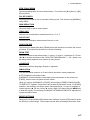
4.2.1
NMEA Input Sentences
NMEA Input Sentences
Talker
**
GP
LC
**
Format
ZDA
RMC
RMA
GGA
GLL
GP、LC
GP、LC
**
**
**
**
**
**
Information
Time (UTC), Date
GPS ship’s speed, Bearing, Own ship’s position
LC ship’s speed, Bearing, Own ship’s position, Time difference
Own ship’s position (L/L), Ship’s speed
Own ship’s position (L/L)
VTG
SOG, True course
HDT
HDM
HDG
DBT
DPT
MTW
Heading (True)
Heading (Magnetic)
Heading (Magnetic)
Depth (below the transducer, Ver 1.5)
Depth (Ver 2.0)
Water temperature
**: Not specified.
Priority
• Own ship’s position (L/L): GGA>RMC>RMA>GLL
• Ship’s speed: VTG>RMC>RMA
• Heading: HDT>HDG>HDM
• Depth: DPT>DBT
4.2.2
NMEA Output Sentences
NMEA Output Sentences
Talker
VD
VD
VD
VD
VD
VD
Format
VBW
VDR
VHW
VTG
VLW
CUR
Information
STW, SOG
Current direction/speed
STW, Heading
SOG, Course (True)
Trip distance
Multiple-layered current
Interval
1s
3s
1s
1s
3s
3s
NMEA output sentences are changeable as below depending on the [NMEA VERSION] setting on the [I/O] sub menu. See "NMEA VERSION" on page 4-1.
NMEA Ver. 1.5: VDR, VHW, VTG, VLW (Trip distance in water tracking mode only)
NMEA Ver. 2.0: VBW, VDR, VHW, VTG, VLW (Trip distance in water tracking mode
only)
NMEA Ver. 3.0: VBW, VDR, VHW, VTG, VLW, CUR
IEC 61162-1 Ed 2: VBW, VDR, VHW, VTG, VLW (Trip distance in water tracking mode
only)
4-8
4. ADJUSTMENTS
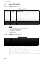
4.2.3
CIF Input/output sentences
Input sentences
Data No.
11
Information
System Time
24、28
Positioning data (L/L)
44、48
Ship’s speed bearing data
57
Depth data
58
Water temperature data
Priority
Information
Priority (No.)
Positioning data
28>24
Ship’s speed bearing data
48>44
Output sentences
Data No.
Information
Interval
56
Single-layered current data
3s
66
Current indicator-measured speed/bearing
3s
76
Multiple-layered current (by depth)
15 s
4.3
External Noise and Interference Check
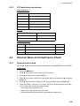
4.3.1
External noise check
Noise level can be measured (without transmission) at the [GENERAL] on the [TEST].
Preparation
1. Press the MENU key.
2. Press S to move the cursor to the top of the screen.
3. Press W several times to select [MENU 1].
4. Press T to move the cursor on the sub menu items, and then press X to choose
[MENU 4].
5. Press T several times to select [TEST], and press X to choose [GENERAL].
6. Press the F1 key. If the NL is –5 or more, the unit is receiving affects of interference. In this case, check the following points.
• Grounding of the transducer unit
• Noise source around the transceiver unit
• Distance between the transducer cable and ship’s power line.
4-9
4. ADJUSTMENTS
CI-68
CI-6888
VOL.
6651201-XX.XX
MEM. 1 2 3
OK
SIO.
OK
CI-6810
VOL.
TBL.
MEM.
ANA.
TRM.
DSW.
DSW.
Noise Level
(Beam1,
Beam2, Beam3
in that order)
NL
-5, -6, -7
TVG ON OFF
6651202-XX.XX
1 2 3 4 5 6 7 8 OK
12V;12.03V BV;110.0V
+25.02 deg.
00 00 00 01
-- 00 00 01
BEAM3
(PORT)
BEAM1
(BOW)
BEAM2
(STBD)
PRESS [MENU] KEY TO QUIT.
XX: Program Version No.
Echo status for three beams
Self test ([GENERAL])
4.3.2
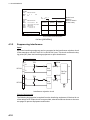
Suppressing interference
Input
Up to two interfering equipment can be connected to the interference rejection circuit
in the transceiver unit via EX KP IN 1 or EX KP IN 2 port. This circuit receives the keying pulse (KP) from the interfering equipment to reject interference.
PCN (66P3924)
TB-4
H
9
[EKP1]
Photo
Coupler
KP IN1
16
CR14
TP2
C
Flip Flop
Circuit
CR15
TP4
11
H
KP IN2
12
C
Photo
Coupler
[EKP2]
S1
Interference rejection circuit
Check of keying pulse
The following keying pulse is required from the interfering equipment. If the level is out
of the ratings or KP output circuit is not provided, take the measures shown on the next
two pages to prevent equipment malfunction.
4-10
4. ADJUSTMENTS
5 to 15 V
less than 1 V
0V
Keying pulse needed
If the level is out of the ratings or KP output circuit is not provided, take the measures
shown on the next two pages to prevent equipment malfunction.
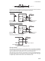
Buffer circuit for positive-going KP
CI-6810
5 to 15V
KP out
2K
TB4
Approx.
300
H
Approx.
300
C
Interfering
Equipment
Additional
Circuit
Interference
Rejector
Buffer circuit for negative-going KP
CI-6810
5 to 15V
KP out
2K
TB4
Approx.
300
H
Approx.
300
Interfering
Equipment
C
Additional
Circuit
Interference
Rejector
The following method also is available.
CI-6810
12 V
TB4
H
C
Interference Rejector
Additional Circuit
Buffer circuit for keying pulse (KP)
DIP switch settings
When KP signal is input to KP IN1, set the switch S1-#3 on the PCN Board 66P3924
to ON. KP signal is positive logic: Set the switch S1-#1 on the PCN Board to OFF. KP
signal is negative logic: Set the switch S1-#1 on the PCN Board to ON
When KP signal is input to KP IN2, set the switch S1-#4 on the PCN Board 66P3924.
KP signal is positive logic: Set the switch S1-#2 on the PCN Board to OFF. KP signal
is negative logic: Set the switch S1-#2 on the PCN Board to ON
4-11
4. ADJUSTMENTS
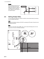
Output
When outputting keying pulse to
suppress interference to other
ultrasound equipment, take the
TX trigger pulse from TB4 (KP
OUT), which is the KP terminal
for external output.
4.4
PCN (66P3924)
5V
TB-4
5V
220 Ω
7 H
CR12
KP OUT
8 C
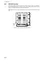
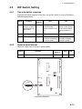
Setting Output Data
You can select data output from TB2-#1 and #2 on the terminal board by the setting
on the PCN Board 66P3924.
Type
Select RS-422 (default setting) or RS-232C by setting the DIP switch J5 and J6 on the
PCN Board 66P3924.
Data
Select the output data among NMEA, CIF, Current data and Display data. Use the
jumper block J8 on the PCN Board 66P3924.
66P3924
Mini connector
TB1
TB3
NMEA/CIF
NMEA/CIF
AUX
422/232C
For RS-232C
J3
J4
J5
J6
1
2
3
4
5
6
7
8
9
CR14
TB2
TB4
CR15
S1
J8
ON/OFF
J7
4-12
J5
J6
J5
J6
1
2
3
4
5
6
7
8
9
For RS-422
Jumper
block
J8
Inscription on PCB
(N_TXD)
CID_DL_TXD
NMEA1_TXD
NMEA2_TXD
DISP_TXD
(CID_DL_RXD)
(NMEA1_RXD)
(NMEA2_RXD)
(DISP_RXD)
䇭䇭䇭䇭䇭䇭䇭䇭䇭Output data
Row data (N value)
Current data (TX)
NMEA1 (TX)
NMEA2(TX): Switchable with CIF on menu
Display data
Current data (RX)
NMEA1 (RX)
NMEA2(RX): Switchable with CIF on menu
Current data
4. ADJUSTMENTS
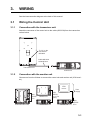
4.5
DIP Switch Setting
4.5.1
Tide calculation response
If the tide calculation response is too slow, set the DIP switch S1 on the PON Board
66P3924 appropriately.
4.5.2
Default
Setting
DIP #
Function
OFF
ON
5
Minute constant
selection (current
response time for
NAV mode)
OFF
Normal
(Normal setting.
Minute constant: 0.05
kn)
Slow
(When current speed
is slow and unstable.
Minute constant: 0.1
kn)
6
Smoothing filter
OFF
YES
NO
7
Bearing addition
OFF
Adds bearing information before averaging
the ship’s speed.
Adds bearing information after averaging
the ship’s speed.
Speed output interval
Select the output interval of ship’s speed display.
DIP #
8
Function
Select output interval of ship’s speed.
Default
Setting
OFF
ON
OFF
3 sec
1 sec
TB1
TB3
66P3924
J3
J4
J5
J6
AUX
CR14
CR15
1
TB2
OFF
TB4
8
S1
S1
ON
J8
J7
PON Board 66P3924
4-13
4. ADJUSTMENTS
4.6
Sea Trial Check
4.6.1
Ship’s speed test
Do the milepost test where ground tracking measurement can be done.
1. Reset the distance run at the moment the milepost test is initiated.
2. Read the distance run at the moment the milepost test is initiated.
3. Calculate true ship’s speed (1) from the data of the milepost test and ship’s speed
of the CI-68 from that of the distance run (2).
4. If the error between (1) and (2) is more than ± (1%+0.1 kn), correct it referring to
the [GT SPD CALIB] on page 4-3. Calibrating is not necessary when the error is
within ± (1%+0.1 kn).
5. Repeat the milepost test several times. Record the data in Table 1.
6. Record the ship’s speed every 10 seconds in table 2.
7. Calculate the average ship’s speed from the data in the Table 2 to compute accuracy.
4.6.2
Current data check
Use the ground tracking mode to record the current (tide) data.
1. Run your boat following the square
course shown below. Each side of the
square is about 1 mile in length.
2. Record the ship’s speed and tide data
every 30 seconds in table 3.
3. On a separate piece of paper, plot the
current speed and direction based on
the table 3. Confirm that the current
reading is stable in any ship’s heading.
(Only when the current changes minimally while the ship runs square
course.)
Ship’s route:
Advance
straight 1
mile approx.
Current
Ship’s route
Confirm that the currents orient the same direction. If not, the interference from other
equipment, air bubbles and noise may be present. Also, take into account that interference from air bubbles may occur since there is no load in the milepost test.
Note: When a bearing sensor is connected in lieu of a gyrocompass, accurate measurement of current direction is not expected because the bearing data itself is in error.
Note that it is difficult to distinguish this unit reading when the above test is done where
the current is complex.
4-14
AVG.
AVG.
AVG.
AVG.
AVG.
DATE
OUTPUT
RPM
ENGINE
(kn)䇭䇭䇭TIME (s)
MILEPOST*1
SHIP YARD
COURSE
(Deg䋩
Mean
WIND
(m/s䋩
(m)
SEA CURRENT
COND.
(kn䋩
SHIP’S LENGTH
Aft
Measuring Mode
GROUND
WATER
Remarks
(m)
Speed ,easured by milepost - Current Indicator Speed
*2 䋺 Error䇭䋽㩷㩷㩷㩷㩷㩷㩷㩷㩷㩷㩷䇭䇭䇭䇭䇭䇭䇭䇭䇭䇭䇭䇭䇭䇭䇭䇭䇭䇭䇭䇭䇭䇭䇭䇭䇭䇭䇭䇭䇭䇭䇭䇭䇭䇭㩷×䇭100
(%)
Speed measured by milepost
DEPTH
(m䋩
DRAFT Fore
Current Indicator
EM-LOG
DIST *3
ERR. (%)*2 (kn䋩
(kn)䇭䇭䇭TIME (s)
Mile (Milepost)
*3 䋺 Current Indicator Speed䇭䋽䇭䇭䇭䇭䇭䇭䇭䇭䇭䇭䇭䇭䇭×䇭3600
Time (sec䋩
SPEED
(kn)
CAPTAIN
SHIP NUMBER
*1 䋺 Milepost䇭䇭䇭䇭䇭䇭䇭䇭䇭䇭䇭䇭䇭 miles
TIME
SHIP’S NAME
TEST SITE
Table 1: Ship’s Speed Test
4. ADJUSTMENTS
4-15
4. ADJUSTMENTS
Table 2: Ship’s Speed Test
TIME
00
10
20
30
40
50
00
10
20
30
40
50
00
10
20
30
40
50
00
10
20
30
40
50
00
10
20
30
10
50
00
4-16
SPD
(kn)
Remarks
TIME
SHIP NUMBER
DEPTH
(m)
TEST SITE
WIND SPEED
COURSE
(ms)
00
10
20
30
40
50
00
10
20
30
40
50
00
10
20
30
40
50
00
10
20
30
40
50
00
10
20
30
40
50
00
SPD
(kn)
Remarks
SHIP NUMBER
DEPTH
(m)
TEST SITE
WIND SPEED
COURSE
(ms)
Depth
SPD
(kn)
DIR
(m)
(m)
LAYER 2
LAYER 3
(m)
LAYER 1
DEPTH
(m)
SHIP’S TYPE
LAYER 1
GROUND / WATER
SHIP’S SHIP’S SPD
HDG. FORE/AFT LEFT/RIGHT
(DEG.) (kn)
(kn)
Measuring mode
1
2
3
4
5
6
7
8
9
10
1
2
3
4
5
6
7
8
No. TIME
SHIP’S NAME
SPD
(kn)
DIR
LAYER 2
DEPTH
(m)
SPD
(kn)
DIR
LAYER 3
Load
DEPTH
(m)
SPD
(kn)
DIR
LAYER 4
TEST DATE
Table 3: Current Display Behaviour Test
DEPTH
(m)
SIGN
SPD
(kn)
DIR
LAYER 5
WIND (REL)
DEPTH SPD
DIR Remarks
(m/s) (DEG.)
(m)
TEST SITE
4. ADJUSTMENTS
4-17
4. ADJUSTMENTS
This page is intentionally left blank.
4-18
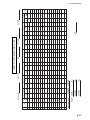
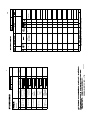
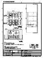
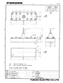
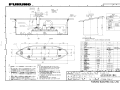
4
3
2
1
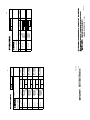
番 号
NO.
CABLE ASSY.
ケーブル組品
CABLE ASSY.
ケーブル組品
CABLE ASSY.
ケーブル組品
CABLE ASSY.
ケーブル組品
略 図
OUTLINE
CI-68/88
000-148-486
000-148-487
000-148-490
CODE NO.
000-148-491
66S1238 *50M*
CODE NO.
66S1238 *30M*
CODE NO.
66S1238 *20M*
CODE NO.
66S1238 *10M*
型名/規格
DESCRIPTIONS
1
1
1
1
数量
Q'TY
1/1
66AS-X-9405
選択 TO BE SELECTED
操作部−送受信演算部
用
FOR CONTROL
UNIT-TRANSCEIVER UNIT
選択 TO BE SELECTED
操作部−送受信演算部
用
FOR CONTROL
UNIT-TRANSCEIVER UNIT
選択 TO BE SELECTED
操作部−送受信演算部
用
FOR CONTROL
UNIT-TRANSCEIVER UNIT
選択 TO BE SELECTED
操作部−送受信演算部
用
FOR CONTROL
UNIT-TRANSCEIVER UNIT
用途/備考
REMARKS
66AS-X-9405 -0
FURUNO ELECTRIC CO .,LTD.
(略図の寸法は、参考値です。 DIMENSIONS IN DRAWING FOR REFERENCE ONLY.)
名 称
NAME
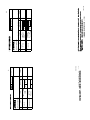
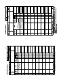
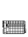
INSTALLATION MATERIALS
工事材料表
TYPE
CODE NO.
A-1
%4+/210.7)
⌕┵ሶ
%4+/210.7)
⌕┵ሶ
ฬޓޓ⒓
0#/'
⇛ޓޓ࿑
176.+0'
%1&'
01
(8㨻㨿
(8
%1&'
01
(8
(8
.(
ဳฬ㧛ⷙᩰ
&'5%4+26+105
%2
ᢙ㊂
36;
↪ㅜ㧛⠨
4'/#4-5
#5: 㧲㨁㧾㨁㧺㧻ޓ㧱㧸㧱㧯㨀㧾㧵㧯ޓ㧯㧻ޓ㧚㧘㧸㨀㧰
㧔⇛࿑ߩኸᴺߪޔෳ⠨୯ߢߔ&ޓޕ+/'05+105+0&4#9+0)(144'('4'0%'10.;㧕
#5:
ဳᑼ㩄㨺㩎㩨⇟ภ߇㧞Ბߩ႐วޔਅᲑࠃࠅᲑߦઍࠊࠆㆊᷰᦼຠߢࠅޔ߅ߥޓޕߔ߹ߡߞ߇߆ࠄߜߤޔຠ⾰ߪᄌࠊࠅ߹ߖ
ࠎޕ
6916;2'5#0&%1&'5/#;$'.+56'&(14#0+6'/6*'.19'4241&7%6/#;$'5*+22'&+02.#%'1(6*'722'4
241&7%637#.+6;+56*'5#/'
⇟ภ
01
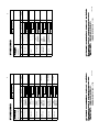
+056#..#6+10/#6'4+#.5
Ꮏ᧚ᢱ
6;2'
%1&'01
A-2
⇟ภ
01
⇛ޓޓ࿑
176.+0'
ᢙ㊂
36;
#5:
↪ㅜ㧛⠨
4'/#4-5
㧲㨁㧾㨁㧺㧻ޓ㧱㧸㧱㧯㨀㧾㧵㧯ޓ㧯㧻ޓ㧚㧘㧸㨀㧰
%1&'01
/,#%
%1&'01
5/
ဳฬ㧛ⷙᩰ
&'5%4+26+105
%2
6;2'
#5: 㧔⇛࿑ߩኸᴺߪޔෳ⠨୯ߢߔ&ޓޕ+/'05+105+0&4#9+0)(144'('4'0%'10.;㧕
9#6'42411(+0)%#2
㩘㩨㨽㩇㨼㩁㨶㨹㩖㩩
%#$.'#55;
㩃㨺㩖㩨㩣⚵ຠ
ฬޓޓ⒓
0#/'
+056#..#6+10/#6'4+#.5
Ꮏ᧚ᢱ
%1&'01
A-3
%122'4564#2
㨻㨺㩇᧼
%4+/210.7)
⌕┵ሶ
ฬޓޓ⒓
0#/'
⇛ޓޓ࿑
176.+0'
%1&'
01
9'#
%1&'
01
9'#41*5
(85
(85
.(
ဳฬ㧛ⷙᩰ
&'5%4+26+105
%2
ᢙ㊂
36;
↪ㅜ㧛⠨
4'/#4-5
#5: 㧲㨁㧾㨁㧺㧻ޓ㧱㧸㧱㧯㨀㧾㧵㧯ޓ㧯㧻ޓ㧚㧘㧸㨀㧰
㧔⇛࿑ߩኸᴺߪޔෳ⠨୯ߢߔ&ޓޕ+/'05+105+0&4#9+0)(144'('4'0%'10.;㧕
#5:
ဳᑼ㩄㨺㩎㩨⇟ภ߇㧞Ბߩ႐วޔਅᲑࠃࠅᲑߦઍࠊࠆㆊᷰᦼຠߢࠅޔ߅ߥޓޕߔ߹ߡߞ߇߆ࠄߜߤޔຠ⾰ߪᄌࠊࠅ߹ߖ
ࠎޕ
6916;2'5#0&%1&'5/#;$'.+56'&(14#0+6'/6*'.19'4241&7%6/#;$'5*+22'&+02.#%'1(6*'722'4
241&7%637#.+6;+56*'5#/'
⇟ภ
01
+056#..#6+10/#6'4+#.5
Ꮏ᧚ᢱ
6;2'
%1&'01
A-4
%4+/210.7)
⌕┵ሶ
%4+/210.7)
⌕┵ሶ
%4+/210.7)
⌕┵ሶ
%122'4564#2
㨻㨺㩇᧼
47$$'45.''8'
㩄㩨㩛㩇㩢㨺㩖㩨
5'.(6#22+0)5%4'9
㩎㩡㩇㩊㨹㩕㩩㩧㩒㩆㩨㩆㨷
⇛ޓޓ࿑
176.+0'
%1&'
01
(8
(8
.(
%1&'
01
(8
.(
%1&'
01
(82
%1&'
01
9'#
9'#41*5
%1&'
01
%1&'
01
:575
ဳฬ㧛ⷙᩰ
&'5%4+26+105
ᢙ㊂
36;
↪ㅜ㧛⠨
4'/#4-5
⧌✢↪ޓޓޓޓޓޓ
(ޓޓ14%14'5
৻㩆㨺㩣㩎㩨㨮㎸⓹㨻㨺㩇
↪(ޓ14)4170&1(
5*+'.�/14
㩆㨺㩣㩎㩨✢↪ޓޓޓޓ
(ޓޓ145*+'.&
㧲㨁㧾㨁㧺㧻ޓ㧱㧸㧱㧯㨀㧾㧵㧯ޓ㧯㧻ޓ㧚㧘㧸㨀㧰
㧔⇛࿑ߩኸᴺߪޔෳ⠨୯ߢߔ&ޓޕ+/'05+105+0&4#9+0)(144'('4'0%'10.;㧕
#.:
ဳᑼ㩄㨺㩎㩨⇟ภ߇㧞Ბߩ႐วޔਅᲑࠃࠅᲑߦઍࠊࠆㆊᷰᦼຠߢࠅޔ߅ߥޓޕߔ߹ߡߞ߇߆ࠄߜߤޔຠ⾰ߪᄌࠊࠅ߹ߖ
ࠎޕ
6916;2'5#0&%1&'5/#;$'.+56'&(14#0+6'/6*'.19'4241&7%6/#;$'5*+22'&+02.#%'1(6*'722'4
241&7%637#.+6;+56*'5#/'
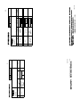
ฬޓޓ⒓
0#/'
*':$1.6
㨻㩖㩩㩈㨹㩎7+㩈㩛㩇$
9#5*'4$+0&+0)
*'#&5%4'9
㧗㩔㩨㨼㩧㩎㩨㩈㩛㩇(
5'.(6#22+0)5%4'9
㩎㩡㩇㩊㨹㩕㩩㩧㩒㩆㩨ޓ㩆㨷
$4#%-'6
㩔㩧㩀㩨㨺
/1706+0)$#5'
㩎㩢㩌㩃㩊㩨㨼
ฬޓޓ⒓
0#/'
⇛ޓޓ࿑
176.+0'
ဳฬ㧛ⷙᩰ
&'5%4+26+105
(2
%1&'
01
/:575
%1&'
01
/:%9/$%4㩕㩡
%1&'
01
:575
%1&'
01
%1&'
01
41*5
41*5
6;2'
%1&'01
ᢙ㊂
36;
↪ㅜ㧛⠨
4'/#4-5
(,: A-6
㧲㨁㧾㨁㧺㧻ޓ㧱㧸㧱㧯㨀㧾㧵㧯ޓ㧯㧻ޓ㧚㧘㧸㨀㧰
㧔⇛࿑ߩኸᴺߪޔෳ⠨୯ߢߔ&ޓޕ+/'05+105+0&4#9+0)(144'('4'0%'10.;㧕
(,:
ဳᑼ㩄㨺㩎㩨⇟ภ߇㧞Ბߩ႐วޔਅᲑࠃࠅᲑߦઍࠊࠆㆊᷰᦼຠߢࠅޔ߅ߥޓޕߔ߹ߡߞ߇߆ࠄߜߤޔຠ⾰ߪᄌࠊࠅ߹ߖ
ࠎޕ
6916;2'5#0&%1&'5/#;$'.+56'&(14#0+6'/6*'.19'4241&7%6/#;$'5*+22'&+02.#%'1(6*'722'4
241&7%637#.+6;+56*'5#/'
⇟ภ
01
#%%'5514+'5
⇟ภ
01
+056#..#6+10/#6'4+#.5
#.: ઃዻຠ
%2
6;2'
Ꮏ᧚ᢱ
%1&'01
A-5
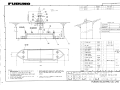
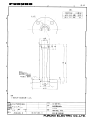
1
番 号
NO.
HOOD ASSY.
フードクミヒン
略 図
OUTLINE
CODE NO.
006-556-240
FP06-01102
型名/規格
DESCRIPTIONS
FP06-01102
TYPE
1
数量
Q'TY
1/1
06AS-X-9503
用途/備考
REMARKS
06AS-X-9503 -3
FURUNO ELECTRIC CO .,LTD.
(略図の寸法は、参考値です。 DIMENSIONS IN DRAWING FOR REFERENCE ONLY.)
名 称
NAME
ACCESSORIES
付属品表
006-556-240
CODE NO.
A-7
9#5*'4$+0&+0)
*'#&5%4'9
㧗㩔㩨㨼㩧㩎㩨㩈㩛㩇(
$4#%-'6
㩖㩨㩡㩃㨹㩎
5'.(6#22+0)5%4'9
㩎㩡㩇㩊㨹㩕㩩㩧㩒㩆㩨㩆㨷
ฬޓޓ⒓
0#/'
⇛ޓޓ࿑
176.+0'
%1&'
01
/:%9/$%4㩕㩡
%1&'
01
41*5
%1&'
01
:575
ဳฬ㧛ⷙᩰ
&'5%4+26+105
(2
ᢙ㊂
36;
↪ㅜ㧛⠨
4'/#4-5
#5: 㧲㨁㧾㨁㧺㧻ޓ㧱㧸㧱㧯㨀㧾㧵㧯ޓ㧯㧻ޓ㧚㧘㧸㨀㧰
㧔⇛࿑ߩኸᴺߪޔෳ⠨୯ߢߔ&ޓޕ+/'05+105+0&4#9+0)(144'('4'0%'10.;㧕
#5:
ဳᑼ㩄㨺㩎㩨⇟ภ߇㧞Ბߩ႐วޔਅᲑࠃࠅᲑߦઍࠊࠆㆊᷰᦼຠߢࠅޔ߅ߥޓޕߔ߹ߡߞ߇߆ࠄߜߤޔຠ⾰ߪᄌࠊࠅ߹ߖ
ࠎޕ
6916;2'5#0&%1&'5/#;$'.+56'&(14#0+6'/6*'.19'4241&7%6/#;$'5*+22'&+02.#%'1(6*'722'4
241&7%637#.+6;+56*'5#/'
⇟ภ
01
#%%'5514+'5
ઃዻຠ
6;2'
%1&'01
A-8
*':$1.6
5.166'&9#5*'4
*'#&
ⷺ㩇㩢㩦㩢㩈㩛㩇$
%15/'6+%2.7)
㩘㨺㩣㩖㩩㩡㩂㩨
5'.(6#22+0)5%4'9
㩎㩡㩇㩊㨹㩕㩩㩧㩒㩆㩨ޓ㩆㨷
%10641.70+6$4#%-'6
㩉㨽㩅㩖㩨㩡㩃㨹㩎
10641.70+6/1706+0)
$#5'
ᠲขઃบ
ฬޓޓ⒓
0#/'
⇛ޓޓ࿑
176.+0'
%1&'
01
/:575
%1&'
01
&2㩂㩥
%1&'
01
:575
%1&'
01
41*5
%1&'
01
ဳฬ㧛ⷙᩰ
&'5%4+26+105
ᢙ㊂
36;
(2
6;2'
↪ㅜ㧛⠨
4'/#4-5
#5: 㧲㨁㧾㨁㧺㧻ޓ㧱㧸㧱㧯㨀㧾㧵㧯ޓ㧯㧻ޓ㧚㧘㧸㨀㧰
㧔⇛࿑ߩኸᴺߪޔෳ⠨୯ߢߔ&ޓޕ+/'05+105+0&4#9+0)(144'('4'0%'10.;㧕
#5:
ဳᑼ㩄㨺㩎㩨⇟ภ߇㧞Ბߩ႐วޔਅᲑࠃࠅᲑߦઍࠊࠆㆊᷰᦼຠߢࠅޔ߅ߥޓޕߔ߹ߡߞ߇߆ࠄߜߤޔຠ⾰ߪᄌࠊࠅ߹ߖ
ࠎޕ
6916;2'5#0&%1&'5/#;$'.+56'&(14#0+6'/6*'.19'4241&7%6/#;$'5*+22'&+02.#%'1(6*'722'4
241&7%637#.+6;+56*'5#/'
⇟ภ
01
#%%'5514+'5
ઃዻຠ
%1&'01
A-9
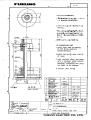
(75'
㩕㨷㨺㩇㩨
()/$8#
2$(
2'4
8'5
ᠲㇱ
#5:
%10641.70+6
52#4'
5'652'4
8'55'.
4'/#4-5%1&'01
㧔⇛࿑ߩኸᴺߪޔෳ⠨୯ߢߔ&ޓޕ+/'05+105+0&4#9+0)(ޓ144'('4'0%'10.;㧕
&9)01
2'4
5'6
914-+0)
37#06+6;
75'
52
6;2'
&9)01
14
6;2'01
(74701'.'%64+%%1.6&
176.+0'
52#4'2#465.+56(14
0#/'1(
2#46
/(450#/'
+6'/
01
5*+201
#5: $1:012
%1&'01
A-10
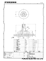
(75'
㩕㨷㨺㩇㩨
()/$8#
2$(
2'4
8'5
#5:
52#4'
5'652'4
8'55'.
4'/#4-5%1&'01
㧔⇛࿑ߩኸᴺߪޔෳ⠨୯ߢߔ&ޓޕ+/'05+105+0&4#9+0)(ޓ144'('4'0%'10.;㧕
&9)01
2'4
5'6
914-+0)
37#06+6;
75'
$1:012
52
6;2'
&9)01
14
6;2'01
(74701'.'%64+%%1.6&
176.+0'
52#4'2#465.+56(14
0#/'1(
2#46
/(450#/'
+6'/
01
5*+201
#5: %1&'01
A-11
(75'
㩕㨷㨺㩇㩨
(75'
㩕㨷㨺㩇㩨
()$1##%8
()$8#
ޓ2$(
()$1##%8
()$8#
ޓ2$(
2'4
8'5
ဳᑼ㩄㨺㩎㩨⇟ภ߇㧞Ბߩ႐วޔਅᲑࠃࠅᲑߦઍࠊࠆㆊᷰᦼຠߢߤࠅޔ߅ߥޓޕߔ߹ߡߞ߇߆ࠄߜޔຠ⾰ߪ
ᄌࠊࠅ߹ߖࠎޕ
6916;2'5#0&%1&'5/#;$'.+56'&(14#0+6'/6*'.19'4241&7%6/#;$'5*+22'&+02.#%'1(6*'
722'4241&7%637#.+6;+56*'5#/'
5'652'4
8'55'.
4'/#4-5%1&'01
#5:
52#4'
㧔⇛࿑ߩኸᴺߪޔෳ⠨୯ߢߔ&ޓޕ+/'05+105+0&4#9+0)(ޓ144'('4'0%'10.;㧕
&9)01
2'4
5'6
914-+0)
37#06+6;
75'
52
6;2'
&9)01
14
6;2'01
(74701'.'%64+%%1.6&
176.+0'
52#4'2#465.+56(14
0#/'1(
2#46
/(450#/'
+6'/
01
5*+201
#5: $1:012
%1&'01
A-12
(75'
㩕㨷㨺㩇㩨
()$1#
#%8
()$8#
ޓ2$(
2'4
8'5
ဳᑼ㩄㨺㩎㩨⇟ภ߇㧞Ბߩ႐วޔਅᲑࠃࠅᲑߦઍࠊࠆㆊᷰᦼຠߢࠅޔ߅ߥޓޕߔ߹ߡߞ߇߆ࠄߜߤޔຠ⾰ߪ
ᄌࠊࠅ߹ߖࠎޕ
6916;2'5#0&%1&'5/#;$'.+56'&(14#0+6'/6*'.19'4241&7%6/#;$'5*+22'&+02.#%'1(6*'
722'4241&7%637#.+6;+56*'5#/'
5'652'4
8'55'.
4'/#4-5%1&'01
#5:
52#4'
㧔⇛࿑ߩኸᴺߪޔෳ⠨୯ߢߔ&ޓޕ+/'05+105+0&4#9+0)(ޓ144'('4'0%'10.;㧕
&9)01
2'4
5'6
914-+0)
37#06+6;
75'
52
6;2'
&9)01
14
6;2'01
(74701'.'%64+%%1.6&
176.+0'
52#4'2#465.+56(14
0#/'1(
2#46
/(450#/'
+6'/
01
5*+201
#5: $1:012
%1&'01
A-13
D-1
Takahashi T.
Y. Hatai
Y. Hatai
D-2
Y. Hatai
D-3
22/Mar/2011
Y.NISHIYAMA
D-4
Y. Hatai
Takahashi T.
D-5
Y. Hatai
D-6
Y. Hatai
Takahashi T.
D-7
D-8
D-9
D-10
D - 11
D-12
D-13
D - 14
D-15
1
2
送受波器
TRANSDUCER
CI-620-1/2 10m(CI-620-1)
20m(CI-620-2),φ18.7
A
クロ BLK
アカ RED
クロ BLK
アカ RED
アカ RED
クロ BLK
ミドリ GRN
アカ RED
クロ BLK
アオ BLU
シロ WHT
キ
YEL
BEAM 1
BEAM 2
BEAM 3
送受信演算部
TRANSCEIVER UNIT
CI-6810
接続箱
JUNCTION BOX
CI-630 *2
1
2
3
4
5
6
7
8
9
10
11
12
Z-6FVNV-SX-C *2
5/10/15/20/30m,φ22
アカ RED
クロ BLK
クロ BLK
1
2
3
4
5
6
7
8
9
10
11
12
アカ RED
アカ RED
クロ BLK
ミドリ GRN
アカ RED
クロ BLK
アオ BLU
シロ WHT
キ
YEL
1
2
4
3
8
10
7
12
14
13
9
11
5
6
*4
W=50
WEA-1004
CN-C6(J1)
GND
TDB1_P
TDB1_N
GND
TDB2_P
TDB2_N
GND
TDB3_P
TDB3_N
GND
URETAN_N
URETAN_P
GND
NC
(出力)
OUT
*1
TTYCY-4S
*1
TTYCY-4S
1
2
3
4
5
6
7
8
CN-C3(TB3)
GYRO_DATA_IN_H
GYRO_DATA_IN_C
GYRO_CLK_IN_H
GYRO_CLK_IN_C
GYRO_DATA_OUT_C
GYRO_DATA_OUT_H
GYRO_CLK_OUT_H
GYRO_CLK_OUT_C
1
2
3
4
5
6
7
8
9
10
11
12
CN-C4(TB4)
LOG_ALM_H
LOG_ALM_C
LOG_200_OUT1_H
LOG_200_OUT1_C
LOG_200_OUT2_H
LOG_200_OUT2_C
KP_OUT_H
KP_OUT_C
KP_IN1_H
KP_IN1_C
KP_IN2_H
KP_IN2_C
*4
警報
ALARM
ログパルス
LOG PULSE
(200P/NM)
TTYCS-1 *1
TTYCS-1 *1
TTYCS-1 *1
TTYCS-1 *1
KP OUT
TTYCS-1 *1
KP IN
TTYCS-1 *1
KP IN
*4
C
66P3924
100/110/115-120/
200/220/230/240VAC
1φ,50/60Hz
24VDC
*1
DPYC(Y)-2.5
*1
DPYCY-6
5
*3
SRCN6A21-10S
CN-C5(J11)
DISP_RX_H 1
DISP_RX_C 2
DISP_TX_H 3
DISP_TX_C 4
GND 5
OP5V_A 6
OP5V_B 7
DC15V_A 8
DC15V_B 9
GND 10
66S1238,10/20/30/50m,φ20
チャ BRN
アカ RED
ダイ ORG
キ
YEL
ミドリ GRN
アオ BLU
ムラサキ PPL
ハイ GRY
シロ WHT
クロ BLK
操作部
CONTROL UNIT
CI-6888
*3
SRCN6A21-10P
1
2
3
4
5
6
7
8
9
10
J2(XH-10P) CN-A1 D-SUB15P
1
R 1
2
G 2
3
B 3
4
GND 4
5
HS_N 5
6
VS_N 6
7
GND 7
8
DISPDCV 8
9
GND 9
10
GND 10
GND 11
MS 12
YS 13
GND 14
0V 15
66P3928
66S1243,0.3m
66P3920
*4
66P3921
方位データ (入力)
IN
BEARING DATA
(AD-10, CURRENT LOOP)
B
4
3
CN-C1(TB1)
NMEA1_TX_H 1
NMEA1_TX_C 2
NMEA1_RX_H 3
NMEA1_RX_C 4
NMEA2/CIF_TX_H 5
NMEA2/CIF_TX_C 6
NMEA2/CIF_RX_H 7
NMEA2/CIF_RX_C 8
CID/DL_TX_H 9
CID/DL_TX_C 10
CID/DL_RX_H 11
CID/DL_RX_C 12
NC 13
*1
IV-2sq.
TTYCS-1 *1
TTYCS-1 *1
TTYCS-1 *1
TTYCS-1 *1
TTYCS-1 *1
TTYCS-1 *1
出力
OUT
入力
IN
出力
OUT
入力
IN
出力
OUT
入力
IN
S-1
6
66S1239,5/10m *2 XM2A-2501
66S1239,0.3m
表示部
MONITOR UNIT
MU-100C
CN-B1(D-SUB25P)
1 R
2 G
3 B
17 GND
4 HS_N
5 VS_N
18 GND
12 12VA
14 GND
15 GND
16 GND
6
19
13
25
YS
GND
0V
12VA
66S1242,0.3m
*1
IV-2sq.
D-SUB15P
航法装置
NAV EQUIPMENT
(IEC61162/NMEA0183)
VGA CABLE *1
外部モニター *1
EXTERNAL MONITOR
航法装置
NAV EQUIPMENT
(NMEA/CIF)
パソコン
PC
(CI-7000,RS-232C)
*4
CN-C2(TB2)
AUX_H 1
AUX_C 2
ON/OFF_H 3
ON/OFF_C 4
NC 5
*4
NC 6
NC 7
NC 8
NC 9
NC 10
TTYCS-1 *1
TTYCS-1 *1
AUX
電源オン・オフ信号
POWER ON/OFF SIGNAL
CN-C7
3
4
DC-ACインバータ
DC-AC INVERTER
(+) TR-2451
*2
(-)
*4
FL1
100VAC(MAX.5A)
W=50
WEA-1004
*1
IV-8sq.
D
注記
*1)造船所手配。
*2)オプション。
*3)コネクタは工場で取付済み。
*4)ケーブルクランプでアースする。
NOTE
*1: SHIPYARD SUPPLY.
*2: OPTION.
*3: CONNECTOR PLUG FITTED AT FACTORY.
*4: GROUND THRU CABLE CLAMP.
DRAWN
22/Mar/2011
CHECKED
22/Mar/2011
APPROVED
22/Mar/2011
SCALE
T.YAMASAKI
H.MAKI
Y.NISHIYAMA
MASS
kg
DWG.No.
C7252-C01- C
REF.No.
66-030-0001-1
TITLE
CI-68
名称
カラー潮流計
相互結線図
NAME
DOPPLER SONAR CURRENT INDICATOR
INTERCONNECTION DIAGRAM