1
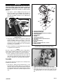
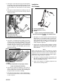
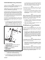
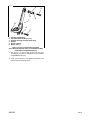
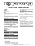
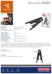
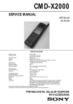
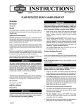
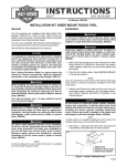
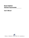
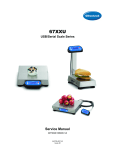
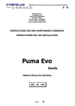
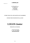
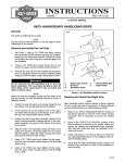
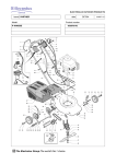
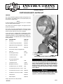
INSTRUCTIONS
REV. 08-13-2004
-J03102
®
Kit Number 69227-04
CUSTOM AUXILIARY LIGHTING KIT
General
8820
This Custom Auxiliary Lighting Kit adds passing lamps and
turn signals to ‘97 and later FLHT, ‘94 and later FLHR, and
‘04 and later FLHRS models.
NOTE
A Service Manual for your model motorcycle is available
from your Harley-Davidson Dealer.
This kit does not include turn signals. Turn signals must be
purchased separately.
This kit does not contain sealed beams or trim rings. Please
see your local Harley-Davidson dealer or use existing sealed
beams and trim rings from motorcycle if equipped.
If your motorcycle is equipped with a windshield, it will be
necessary to purchase separately and use kit 69235-04. For
windshield installation on stock FLHRS models it will be necessary to purchase kit 69234-04 which includes windshield
docking bushings.
QTY
DESCRIPTION
PART NO.
2
Nest Ring
68331-02
1
Left Side Passing Lamp Bracket
68836-04
1
Right Side Passing Lamp Bracket
68837-04
2
Directional Stand Off
68821-00
2
Chrome Spot Lamp Housing 68822-04
4
Cable Ties
10181
2
Sheathing (Black Vinyl)
Not Sold
2
Lock Nut, Nylon 3/8 in.
7667
2
Lockwasher 3/8 in.
2
Hex Socket Head Screw
5/16-18 x 2-1/4 in.
4296
2
Lockwasher 5/16 in.
7130W
8
Butt-Splice Connectors
70585-93
2
Flat Washer 3/8 in. ID, 1.0 in. OD
6645
1
Torx Head Screw 5/16-18 x 1-1/2 in.
4784
4
Torx Head Screw 5/16-18 x 1-1/4 in.
94602-98
4
Flat Washer 7/16 in. ID, 3/4 in. OD
57920-04
1
Clamp Spacer
65832-92
2
Rubber Washer
40901-05
1
2
1.
2.
OEM passing lamp
Bracket assembly
Figure 1.OEM Passing Lamp Assembly (typical)
7041
1WARNING
The rider’s safety depends upon the correct installation
of this kit. Use the appropriate Service Manual procedures. If the procedure is not within your capabilities or
you do not have the correct tools, have a HarleyDavidson dealer perform the installation. Improper
installation of this kit could result in death or serious
injury. (00333a)
1WARNING
To prevent accidental vehicle start-up, which could
cause death or serious injury, disconnect battery cables
(negative (-) cable first) before proceeding. (00307a)
Items in this kit are not sold separately.
-J03102
1 of 5
1WARNING
Disconnect negative (-) battery cable first. If positive (+)
cable should contact ground with negative (-) cable connected, the resulting sparks can cause a battery explosion, which could result in death or serious injury.
(00049a)
10
11
1. See Figure 1. Remove OEM passing lamp (1) and
bracket assembly (2) (if equipped) per procedure in
appropriate Service Manual. Retain sealed beams and
trim rings from OEM assembly for use in new passing
lamp assembly.
9
13
12
1
8
i06169
7
11
5
2
12
6
1
Figure 2. Typical Mounting Screw Locations
(FLHRS Shown)
2. See Figure 2. On FLHRS models. Remove and discard
original mounting screws (1). Repeat for other side.
Remove handlebar mounted turn signals, acorn nuts,
internal tooth washers, signals, mounting blocks from
handlebars and install OEM acorn nuts and internal
tooth washers to retain mirrors.
4
1.
2.
3.
4.
5.
6.
7.
8.
9.
10.
11.
12.
13.
Passing Lamp Bracket
Directional Stand Off)
Directional Assembly (wires not shown)
Lock Nut (Nylon)
Lock Washer
Washer
Lock Washer (5/16 in.)
Hex Socket Screw, 5/16-18 x 2-1/4 in.
Nest Ring
Spot Lamp Housing
Washer
Screw, Torx Head 5/16-18 x 1-1/4 in.
Rubber Washer
Figure 3. Passing Lamp Assembly
(shown without wiring for assembly clarity)
3. Remove headlamp and headlamp bucket per procedure
in appropriate Service Manual.
NOTE
Be sure to label or mark all wires before cutting them to
ensure proper installation and function of kit. Be sure to cut
wires in places easily concealed for a clean kit installation.
i06170
1
4. Refer to approprioate Service Manual to locate turn signal connectors and passing lamp connectors. Label, cut
and strip wires (purple, blue, black and grey for passing
lamps), in preparation for passing lamp kit installation.
Assembly
3
2
The Passing Lamp Kit will require basic assembly before
installation on motorcycle.
1. See Figure 3. Aquire passing lamp bracket (1), spot
lamp housing (10), rubber washer (13), lock washer (5),
and nylon lock nut (4) and Install spot lamp housing into
passing lamp bracket. Retain with lockwasher and lock
nut. Tighten to 14-18 ft-lbs (19-24 Nm). Repeat for other
side.
-J03102
Figure 4. Passing Lamp Wiring Routing Shown
2. Aquire grey wire from kit. Tie small knot in terminal end
of wire approximately 3-4 inches from terminal to avoid
wire getting pulled too far into housing during installation.
2 of 5
3. See Figure 4. Insert bare end of grey wire through hole
in mounting stud on passing lamp housing (1) and
through larger passage in passing lamp bracket until
knot in terminal end of wire bottoms in socket housing
(2).
Installation
FLHT Models
i06114a
4. See Figure 3. Aquire directional assembly (3) from kit,
directional stand off (2), hex socket screw (8), and lock
washer (7) from kit.
i06171
3
2
1
3
2
4
1
3
2
1.
2.
3.
4.
Grey Wire (to passing lamp)
Blue Wire (to parking lamp)
Black Wire (to ground)
Violet/Brown Wire (to directional)
Figure 5. Directional Wiring Routing Shown
5. See Figure 5. Install directional assembly (3) from kit to
stand off (2) by routing wires through directional stand
off and passage in passing lamp bracket (1) along side
grey wire from step 3. See Figure 3. Secure directional
assembly using lock washer (7) and hex socket head
screw. (8). Tighten to 96-120 in.lbs (10.8-13.6 Nm).
Repeat for other side.
i06172
1
2
3
1. Wire Sheathing
2. Wires
3. Passing Lamp Bracket Passage (apply silicone)
1. Passing Lamp Bracket
2. Torx Head Screw (1-1/4 in.)
3. Washer
Figure 7. Passing Lamp Bracket Assembly
(left-side shown bare for clarity as installed on FLHT
models)
1. See Figure 7. For FLHT models. Hold left side passing
lamp bracket (1) in mounting position on motorcycle.
Install two torx head screws (2) and washers (3) into
passing lamp bracket assembly (1) and attach passing
lamp bracket to motorcycle. Tighten to 12-16 ft-lbs (1622 Nm). Repeat for right side.
2. Connect wires from passing lamp assembly to existing
marked wires on motorcycle using butt-splices from kit.
Splice wires according to procedure in appropriate
Service Manual.
NOTE
When connecting wires from passing lamp kit to existing
motorcycle wires, match colors to colors (i.e. purple wire to
purple wire). Be sure to test ALL functions of kit before operating motorcycle to ensure proper operation. Refer to appropriate vehicle wiring schematic if in question.
3. See Figure 3. Install passing lamp sealed beams and
trim rings according to procedure in appropriate Service
Manual using new Nest Rings (9).
4. Verify correct operation of all lighting components and
switches before operating vehicle.
Figure 6. Installing Wire Sheating
6. See Figure 6. Install wire sheathing (1) onto wires (2).
Insert a small amount of silicone into passage (3) of
passing lamp bracket and firmly slide sheathing into
passage and allow to dry before installing.
7. After silicone has dried, place a wire tie approximately 1
in. from the the siliconed area, clinch around sheathing
to retain it in place.
-J03102
3 of 5
FLHR/FLHRS Models Using a Windshield
NOTE
FLHR and FLHRS models aready equipped with a windshield will also require hardware kit 69235-04 which contains three 1-1/2 in. long and one 1-3/4 in. bolts.
FLHRS models can be made “windshield ready” by using
hardware kit 69235-04 which contains three 1-1/2 in. bolts,
one 1-3/4 in. bolt and four docking bushings.
It will be necessary to utilize the 1/8 in. spacer included in
the passing lamp main kit for installation. This spacer will be
positioned on the lower mounting bolt between the nacelle
and the docking bushing on motorcycles with windshield as
seen in Figure 8, and on the lower mounting bolt between
the nacelle and passing lamp bracket on motorcycles without a windshield as seen in Figure 9.
See Figure 8. On FLHT/FLHR models, the .150 in. spacer
(5) will not be used. On FLHRS models, install clutch cable
P-clamp (3) between washer and spacer as shown in
Figures 8 and 9.
1. For FLHR models, hold left side passing lamp bracket
(1) in mounting position on motorcycle. Install 1/8 in.
spacer (7), bushing (6), washer (4), and 1-1/2 in. torx
head screw (2) in top and bottom locations. Tighten to
12-16 ft-lbs (16-22 Nm). Repeat for right side. See
Figure 9.
i06114c
3
2
6
5
7
4
1
6
4
2
1. Passing Lamp Bracket
2. Torx Head Screw FLHR (1-1/2 in.) (1-3/4 in. for
FLHRS top-left only)
3. P-Clamp (existing part from motorcycle)
4. Washer
5. Spacer (.150 in.) FLHRS only
6. Docking Bushing
7. Spacer (1/8 in.)
in. torx head screw (2). Pivot passing lamp bracket
upward. Install docking bushing (6), .150 in. spacer (5),
clutch cable P-clamp (3), washer (4) and 1-3/4 in. torx
head screw (2). Tighten to 12-16 ft-lbs (16-22 Nm).
NOTE
For right side use 1/8 in. spacer (6), washer (4), and 1-1/2
in. torx head screw (2) at top and bottom locations. Tighten
to 12-16 ft-lbs (16-22 Nm)
3. Connect wires from passing lamp assembly to existing
marked wires on motorcycle using butt-splices from kit
and splice wires according to procedure in appropriate
Service Manual.
NOTE
When connecting wires from passing lamp kit to existing
motorcycle wires, match colors to colors (i.e. purple wire to
purple wire). Be sure to test ALL functions of kit before operating motorcycle to ensure proper operation. Refer to appropriate vehicle wiring schematic if in question.
4. See Figure 3 Install sealed beams and trim rings
according to procedure in appropriate Service Manual
using new Nest Rings (9).
5. Verify correct operation of all lighting components and
switches before operating vehicle.
FLHRS Models not Using a Windshield
NOTE
See Figure 9. On FLHT/FLHR models, the .150 in. spacer
(5) will not be used. On FLHRS models, install clutch cable
P-clamp (3) between washer and spacer as shown in
Figures 8 and 9.
1. See Figure 9. For FLHRS models without windshield
mounting. Hold left side passing lamp bracket (1) in
mounting position on motorcycle. Install 1/8 in. spacer
(6) washer (4), 1-1/4 in. torx head screw (2). Pivot passing lamp bracket upward. Install .150 in. spacer (5) into
passing lamp arm. Install clutch cable P-clamp (3),
washer (4) and 1-1/2 in. torx head screw (2). Tighten to
12-16 ft-lbs (16-22 Nm).
NOTE
For right side use 1/8 in. spacer (7), washer (4), and 1-1/4
in. torx head screw (2) at top location and bottom locations.
Tighten to 12-16 ft-lbs (16-22 Nm).
2. Connect wires from passing lamp assembly to existing
marked wires on motorcycle using butt-splices from kit
and splice wires according to procedure in appropriate
Service Manual.
NOTE
When connecting wires from passing lamp kit to existing
motorcycle wires, match colors to colors (i.e. purple wire to
purple wire). Be sure to test ALL functions of kit before operating motorcycle to ensure proper operation. Refer to appropriate vehicle wiring schematic if in question.
Figure 8. Passing Lamp Bracket Assembly
(left-side shown bare for clarity as installed on FLHR/
FLHRS models w/windshield docking)
2. For FLHRS models, hold left side passing lamp bracket
(1) in mounting position on motorcycle. Install 1/8 in.
spacer (7), docking bushing (6), washer (4), and 1-1/2
-J03102
4 of 5
i06114b
3
5
2
4
1
6
4
2
1.
2.
3.
4.
5.
6.
Passing Lamp Bracket
Torx Head Screw FLHR (1-1/2 in.)
P-Clamp (existing part from motorcycle)
Washer
Spacer (.150 in.)
Spacer (1/8 in.)
Figure 9. Passing Lamp Bracket Assembly
(left-side shown bare for clarity as installed on FLHRS
model without windshield docking)
3. See Figure 3. Install sealed beams and trim rings
according to procedure in appropriate Service Manual
using new Nest Rings (9).
4. Verify correct operation of all lighting components and
switches before operating vehicle.
-J03102
5 of 5