1
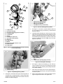
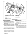
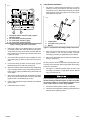
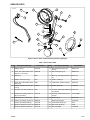
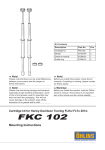
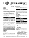
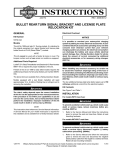
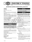
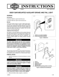
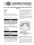
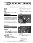
-J03966
REV. 2011-12-01
CUSTOM AUXILIARY FORWARD LIGHTING KIT
Refer to the appropriate Service Manual and remove left
and right turn signal wires from pin connectors. Note location of wires before removal.
GENERAL
Kit Number
69818-06, 68000042
4.
Models
This Custom Auxiliary Lighting Kit adds lamps and turn signals
to 2006 and later FLHX model motorcycles.
Additional Parts Required
Remove original equipment turn signals per procedure in
appropriate Service Manual and retain both left and right
side turn signals.
NOTE
Be sure to label or mark all wires before removing them to
confirm proper installation and function of kit.
This kit does not include turn signals. You will be removing the
original turn signals and re-positioning them onto the new
auxiliary mount.
5.
This kit does not contain sealed beams. See your local HarleyDavidson dealer for your sealed beam lights.
Auxiliary Lamp Assembly
Refer to appropriate Service Manual to locate turn signal
connectors and auxiliary lamp connectors in preparation
for auxiliary lamp kit installation.
NOTE
The rider's safety depends upon the correct installation
of this kit. Use the appropriate service manual procedures.
If the procedure is not within your capabilities or you do
not have the correct tools, have a Harley-Davidson dealer
perform the installation. Improper installation of this kit
could result in death or serious injury. (00333a)
NOTE
This instruction sheet references Service Manual information.
A Service Manual for your model motorcycle is required for
this installation and is available from a Harley-Davidson dealer.
The Auxiliary Lamp Kit will require basic assembly before
installation on motorcycle.
1.
See Figure 1. Acquire lamp bracket (1), lamp housing (10),
rubber washer (13), clamp block (14), lock washer (5),
and nylon lock nut (4) and install lamp housing into lamp
bracket. Retain with lockwasher and lock nut. Tighten to
14-18 ft-lbs (19-24 Nm). Repeat for other side.
2.
Acquire grey wire from kit. Tie small knot in terminal end
of wire approximately 3-4 inches from terminal to avoid
wire getting pulled too far into housing during installation.
Kit Contents
See Figure 8 and Table 1.
REMOVAL
To prevent accidental vehicle start-up, which could cause
death or serious injury, disconnect battery cables (negative
(-) cable first) before proceeding. (00307a)
Disconnect negative (-) battery cable first. If positive (+)
cable should contact ground with negative (-) cable connected, the resulting sparks can cause a battery explosion,
which could result in death or serious injury. (00049a)
1.
Disconnect the battery cables, negative (-) cable first.
2.
Refer to the appropriate Service Manual and remove outer
fairing from motorcycle.
3.
Locate and disconnect the left and right turn signal connectors per procedure in appropriate Service Manual.
-J03966
Many Harley-Davidson® Parts & Accessories are made of plastics and metals which can be recycled.
Please dispose of materials responsibly.
1 of 5
is02138
is02140
10
11
12
9
1
13
4
8
7
1
11
3
12
6
2
1.
2.
3.
4.
14
2
5
3
Figure 3. Directional Wiring Routing Shown
4
1.
2.
3.
4.
5.
6.
7.
8.
9.
10.
11.
12.
13.
14.
Lamp bracket
Directional standoff
Directional assembly (wires not shown)
Lock nut (nylon)
Lock washer
Washer
Lock washer (5/16 inch)
Hex socket screw, 5/16-18
Nest ring
Lamp housing
Washer
Screw, Torx head, 5/16-18 x 1-1/4
Rubber washer
Clamp block
Grey wire (to auxiliary lamp)
Blue wire (to parking lamp)
Black wire (to ground)
Violet/Brown wire (to directional)
4.
See Figure 1. From the kit, acquire directional stand off
(2), hex socket screw (8), lock washer (7) and directional
removed in step 4.
5.
Install directional assembly (3) to stand off (2) by routing
wires through directional stand off and passage in lamp
bracket (1) along side grey wire from step 3. Secure directional assembly using lock washer (7) and hex socket head
screw. (8). Tighten to 96-120 in-lbs (10.8-13.6 Nm).
Repeat for other side.
is02141
1
2
Figure 1. Auxiliary Lamp Assembly (shown without wiring
for assembly clarity)
3
is02139
1
1. Wire sheathing
2. Wires
3. Lamp bracket passage (apply silicone)
2
1. Auxiliary lamp housing
2. Socket housing
Figure 4. Installing Wire Sheathing
6.
See Figure 4. Install wire sheathing (1) onto wires (2).
Insert a small amount of silicone into passage (3) of lamp
bracket and firmly slide sheathing into passage and allow
to dry before installing.
7.
After silicone has dried, place a wire tie approximately 1
inch from the the siliconed area, clinch around sheathing
to retain it in place.
8.
Refer to appropriate Service manual and attach left and
right turn signal connectors to turn signal wires.
Figure 2. Lamp Wiring Routing Shown
3.
See Figure 2. Insert bare end of grey wire through hole in
mounting stud on lamp housing (1) and through larger
passage in lamp bracket until knot in terminal end of wire
bottoms in socket housing (2).
-J03966
2 of 5
is02176
13
12
1
8
9
3
8
10
10
7
12
7
2
6
11
1. Fairing cap (inner)
2. Fairing cap switch connector [105], 12-place Multilock (black)
3. Auxiliary light switch
4. Wire, black (ground)
5. Wire, yellow
6. Wire, gray
7. Fairing cap fastener screw holes
5
4
8.
9.
10.
11.
12.
13.
Switch bracket screws (2)
Switch bracket
Wire ties (3)
Flexible clamp
Rubber grommets (2)
Accessory switch
Figure 5. Fairing Cap (Inner)
Auxiliary Lamp Switch Assembly
Auxiliary Switch Connection
1.
Refer to the appropriate Service Manual and partially disassemble ignition switch.
1.
2.
See Figure 5. Remove two T27 TORX® screws (with flat
washers) (7) to release fairing cap (1) from left and right
sides of inner fairing.
3.
With the front forks turned to the left fork stop, reach
behind right side of fairing cap and disconnect the fairing
cap switch connector [105], 12-place Multilock (black) (2)
from the wiring harness.
4.
Remove fairing cap from motorcycle. If wire ties are
wrapped around the accessory switch wires, remove wire
ties and discard.
5.
Remove two T25 TORX screws (8) to release switch
bracket (9) from fairing cap.
6.
Place auxiliary light switch (3) into the fairing cap left side
switch position with switch light towards rear of motorcycle.
Route switch wires through switch bracket and position
switch bracket over auxiliary switch. Press switch bracket
onto switch.
7.
Install two T25 TORX screws (8) to secure auxiliary switch
(3) to fairing cap (1).
-J03966
See Figure 5. With the fairing cap (inner) positioned close
to the motorcycle, find the yellow (5), gray (6), and black
(4) auxiliary switch wires.
NOTE
The fairing cap switch connector [105], 12-place Multilock
(black) has numbers stamped into the secondary lock of the
socket housing.
2.
See Figure 6. Position the fairing cap switch connector
[105], 12-place Multilock (black) (1) as shown. Find the
auxiliary switch black (GRN) wire and insert pin terminal
into position 8 (4). Find gray wire and insert pin terminal
into position 7 (3). Find yellow wire and insert pin terminal
into position 6 (2).
3 of 5
Lamp Bracket Installation
is02178
1.
See Figure 7. Hold left side lamp bracket (1) in mounting
position on motorcycle. Install two torx head screws (2)
and washers (3) into lamp bracket assembly and attach
lamp bracket to motorcycle. Tighten to 12-16 ft-lbs (16-22
Nm). Repeat for right side.
5
4
3
2
1
is02142
1
3
2
2
1
– AMP
6
3
7
8
9
10
11
12
4
3
1. Fairing cap switch connector [105], 12-place
Multilock (black)
2. Pin connection, position 6 (yellow)
3. Pin connection, position 7 (gray)
4. Pin connection, position 8 (black)
1. Lamp bracket
2. Torx head screw (1-1/4 inch)
3. Washer
Figure 6. Fairing cap switch connections
3.
4.
See Figure 5. Bend up the flexible clamp (11) and place
the auxiliary switch wires under flexible clamp and press
clamp down onto wires. From the kit find three new wire
ties (10) and secure accessory and auxiliary switch wires
together as shown.
Check that rubber grommets (12) are installed on each
side of fairing cap (1). Barbs on cap fit into holes in grommets.
5.
Connect the fairing cap switch connector [105], 12-place
Multilock (black) on the right side of fairing cap.
6.
With the front forks turned to the left fork stop, install fairing
cap over ignition switch housing. Check that grommets in
fairing cap fully capture handlebar along with throttle and
clutch cables.
7.
Start two T27 TORX screws (with flat washers) to fasten
fairing cap to left and right sides of inner fairing. Alternately
tighten screws to 25-30 in-lbs (2.8-3.4 Nm).
8.
Refer to the appropriate Service Manual and assemble
ignition switch.
9.
Install switch decal on switch.
-J03966
2
Figure 7. Lamp Bracket Assembly (left dide shown bare)
2.
Route and connect left and right turn signal wires from
lamp assembly to left and right harness connectors
according to procedure in appropriate Service Manual.
3.
Refer to the appropriate Service Manual and install outer
fairing on motorcycle.
NOTE
Be sure to test ALL functions of kit before operating motorcycle
to confirm proper operation. Refer to appropriate vehicle wiring
schematic if in question.
4.
See Figure 1. Install lamp sealed beams and trim rings
according to procedure in appropriate Service Manual
using new nest rings (9).
Connect positive (+) battery cable first. If positive (+) cable
should contact ground with negative (-) cable connected,
the resulting sparks can cause a battery explosion, which
could result in death or serious injury. (00068a)
5.
Connect the battery cables, positive (+) cable first.
6.
Check the correct operation of all lighting components and
switches before operating vehicle.
4 of 5
SERVICE PARTS
is02135a
10
14
23
1
2
17
15
13
5
4
20
1
3
2
16
21
9
6
11
22
7
Figure 8. Service Parts: Custom Auxiliary Forward Lighting Kit
Table 1. Service Parts Table
Item
Description (Quantity)
Part Number
Item
Description (Quantity)
Part Number
1
Washer, flat (4)
57920-04
12
Bar, Passing lamp, RH (not
shown)
68837-04A
2
Screw, Torx socket button head,
5/16-18 x 1.25 inch (4)
94602-98
13
Bar, Passing lamp, LH
68836-04A
3
Washer (2)
6645
14
Nest ring, pass/fog/pursuit lamps 68331-02
(2)
4
Washer, lock 5/16 inch (2)
7041
15
Isolator, rubber (2)
40901-05
5
Screw, Torx socket button head,
5/16-18 (2)
4296
16
Clamp block, passing lamp (2)
69563-06
6
Washer, internal tooth lock, 3/8
inch (2)
7130W
17
Switch, spot lamp
71505-96
7
Nut, Nylon lock, 3/8-16 UNC (2)
7667
18
Terminal, socket #20-16AWG (10) 73191-96
(not shown)
8
Extruded vinyl tubing, 0.38 inch
dia. (2) (not shown)
70561-90
19
Housing, 4-way socket (2) (not
shown)
73154-96BK
9
Cable tie, 0.91 x 7.82 inch (6)
10181
20
Bezel ring (2)
68725-62A
10
Housing, spot lamp, chrome (2)
68822-04
Bezel ring, black (2)
67700120
Housing, spot lamp, black (2)
73340-10
21
Screw, bezel, #8-32 (2)
3514
Stand off, directional, chrome (2) 68821-00
22
Nut, bezel, #8-32 (2)
7606
Stand off, directional, black (2)
23
Decal, spotlight
15339-98
11
-J03966
73333-10
5 of 5