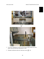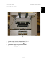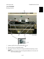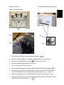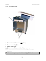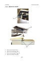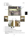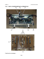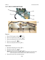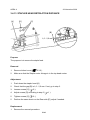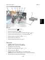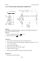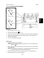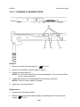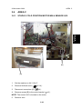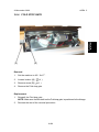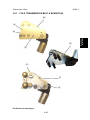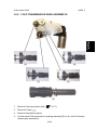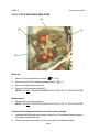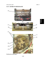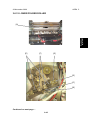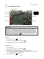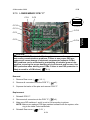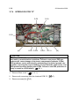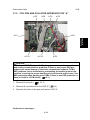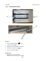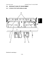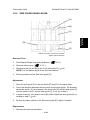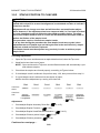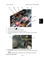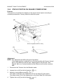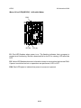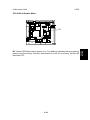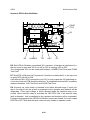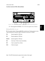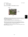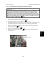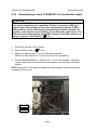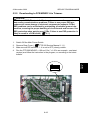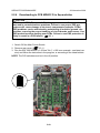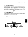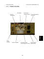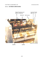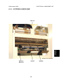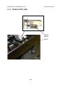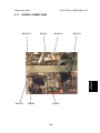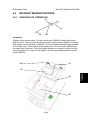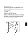
1
BOOKLET MAKER BM 200
SERVICE MANUAL
29 November 2006
Subject to change
Page intentionally blank
IMPORTANT SAFETY NOTICES
PREVENTION OF PHYSICAL INJURY
Always connect the equipment to a
properly grounded power source. In doubt, have
the power source checked by a qualified
electrician.
Never use a ground adapter plug to
connect the equipment to a power source that
lacks a ground connection terminal.
Never attempt any maintenance function
that is not specifically described in this
documentation.
WARNING: Improper connection of the
equipment grounding conductor can result
in electrical shock.
Never remove the covers or guards that
are fastened with screws, unless you are a
trained Service representative.
Always follow all warnings marked on, or
supplied with, the equipment.
Always locate the equipment on a solid
support surface with adequate strength for
the weight of the machine.
Always exercise care in moving or
locating the equipment.
Never install the unit near a radiator or any
other heat source.
Never override or “cheat” electrical or mechanical interlock devices.
re-
Never operate the equipment if you notice
unusual noises or odors. Disconnect the
power cord from the power source and call
your customer service engineer to correct
the problem.
Always keep magnets and all devices with
strong magnetic field away from the
machine.
1. Before disassembling or assembling parts of the Booklet maker and peripherals.
make sure that the Booklet maker power cord is unplugged,
2. The wall outlet should be near the Booklet maker and easily accessible.
3. Note that some components of the Booklet maker and peripherals are supplied
with electrical voltage even if the main power switch is turned off.
4. If any adjustment or operation check has to be made with exterior covers off or
open while the main switch is turned on, keep hands away from electrical or mechanically driven components.
OBSERVANCE OF ELECTRICAL SAFETY STANDARDS
1. The Booklet maker and its peripherals must be installed and maintained by a
customer service representative who has completed the training course on those
models.
SAFETY AND ECOLOGICAL NOTES FOR DISPOSAL
1.
Dispose of replaced parts in accordance with local regulations.
III
Page intentionally blank
TABLE OF CONTENTS
1 INSTALLATION PROCEDURE
1.1 INSTALLATION REQUIREMENTS........................................................... 1-1
1.1.1 MINIMUM SPACE REQUIREMENTS.............................................. 1-1
1.1.2 POWER REQUIREMENTS.............................................................. 1-2
1.2 INSTALLATION FLOW CHART................................................................ 1-3
1.3 BOOKLET MAKER INSTALLATION......................................................... 1-5
1.3.1 ACCESSORY CHECK..................................................................... 1-5
1.3.2 INSTALLATION PROCEDURE........................................................ 1-6
1.3.3 ADJUSTMENTS............................................................................... 1-7
1.3.4 CONNECTORS.............................................................................. 1-10
1.4 TRIMMER INSTALLATION..................................................................... 1-11
1.4.1 ACCESSORY CHECK................................................................... 1-11
1.4.2 INSTALLATION PROCEDURE...................................................... 1-12
1.4.3 ADJUSTMENTS............................................................................. 1-14
1.4.4 DOCKING........................................................................................ 1-17
1.4.5 CONNECTORS.............................................................................. 1-20
1.5 SQUAREFOLDER INSTALLATION........................................................ 1-23
1.5.1 ACCESSORY CHECK................................................................... 1-23
1.5.2 INSTALLATION PROCEDURE...................................................... 1-24
1.5.3 ADJUSTMENTS............................................................................. 1-27
1.5.4 DOCKING........................................................................................ 1-30
1.5.5 CONNECTORS.............................................................................. 1-32
1.5.6 AUTO SET THICKNESS BRACKET.............................................. 1-33
2.PREVENTIVE MAINTENANCE SCHEDULE
2.1 PM TABLE................................................................................................ 2-1
3.REPLACEMENT AND ADJUSTMENT
3.1 GENERAL CAUTIONS............................................................................. 3-1
3.2 SPECIAL TOOLS AND LUBRICANTS..................................................... 3-3
3.2.1 SPECIAL TOOLS............................................................................. 3-3
3.2.2 REQUIRED TOOLS......................................................................... 3-5
3.2.3 SYMBOLS USED IN TEXT.............................................................. 3-5
3.3 COVERS................................................................................................... 3-7
3.3.1 FRONT AND REAR COVER............................................................ 3-7
3.3.2 INFEED COVER.............................................................................. 3-8
3.3.3 INFEEDER....................................................................................... 3-9
3.3.4 OUTFEED COVER........................................................................ 3-10
3.3.5 UPPER TOP COVER..................................................................... 3-11
3.3.6 REAR TOP COVER....................................................................... 3-12
3.3.7 TOP COVER ASSEMBLY.............................................................. 3-13
3.3.8 INTERLOCK SWITCH S16 &S17.................................................. 3-15
3.4 AREA A................................................................................................... 3-17
3.4.1 INFEED MODULE.......................................................................... 3-17
3.4.2 PAPER INFEED SENSOR............................................................. 3-18
3.4.3 INFEED TRANSPORT MODULE................................................... 3-19
3.4.4 INFEED TRANSPORT WHEEL..................................................... 3-20
3.4.5 INFEED MOTOR M1 & SENSOR Q2............................................ 3-21
3.4.6 SIDE GUIDES................................................................................ 3-22
3.4.7 SIDE JOGGER MOTOR M3 & SENSOR Q12............................... 3-23
3.4.8 SIDE GUIDE TRANSMISSION &SENSOR Q13............................ 3-24
3.4.9 BACK JOGGER MODULE & SENSOR Q3................................... 3-26
3.4.10 BACK JOGGER FINGERS............................................................ 3-28
3.4.11 BACK JOGGER MOTOR M2......................................................... 3-30
3.4.12 STAPLER HEAD............................................................................ 3-31
3.4.13 STAPLER HEAD RETRACTION DISTANCE................................. 3-34
3.4.14 STAPLER MOTOR M4................................................................... 3-35
3.4.15 STAPLER ASSY DRIVE BAR & SENSOR Q14............................. 3-36
3.4.16 CLINCHER BAR ASSEMBLY......................................................... 3-37
3.4.17 CLEANING CLINCHER POINTS................................................... 3-38
3.4.18 SET TRANSPORT DRIVE ALIGNMENT........................................ 3-39
3.4.19 PRESSURE ROLLER.................................................................... 3-41
3.4.20 SET TRANSPORT MOTOR M5..................................................... 3-42
3.4.21 THICK SET SENSOR Q36............................................................. 3-43
3.5 AREA B................................................................................................... 3-45
3.5.1 STAPLE STOP GATE SOLENOID SOL1....................................... 3-45
3.5.2 STAPLE STOP GATE RELEASE SOLENOID SOL2..................... 3-46
3.5.3 SADDLE STAPLING START SENSOR Q4.................................... 3-48
3.6 AREA C................................................................................................... 3-49
3.6.1 STAPLE / FOLD POSITION MOTOR M9 & SENSOR Q10........... 3-49
3.6.2 LENGTH TRANSMISSION SHAFT & SENSOR Q11.................... 3-50
3.6.3 FOLD STOP GATE MOTOR M8 & SENSOR Q7........................... 3-52
3.6.4 FOLD STOP GATE........................................................................ 3-53
3.6.5 FOLD KNIFE MOTOR M7 & SENSOR Q15.................................. 3-54
3.6.6 FOLD TRANSMISSION MODULE................................................. 3-56
3.6.7 FOLD TRANSMISSION BELT & SENSOR Q9.............................. 3-57
3.6.8 FOLD ROLLER MOTOR M6.......................................................... 3-59
3.6.9 FOLD TRANSMISSION GEAR ASSEMBLYS................................ 3-61
3.6.10 FOLD DISTANCE BRACKET......................................................... 3-62
3.6.11 UPPER FOLDER ROLLER............................................................ 3-63
3.6.12 LOWER FOLDER ROLLER........................................................... 3-65
3.6.13 OUTFEED SENSOR...................................................................... 3-67
3.7 PCB........................................................................................................ 3-69
3.7.1 MD3DC PCB “H”............................................................................ 3-69
3.7.2 UPPER MD6DC PCB ”B”............................................................... 3-70
3.7.3 LOWER MD6DC PCB ”C”.............................................................. 3-71
3.7.4 INTERLOCK PCB ”D”.................................................................... 3-72
3.7.5 CPU PCB AND COLLATOR INTERFACE PCB ”A”....................... 3-73
3.7.6 ADDON PCB ”F”............................................................................ 3-75
3.7.7 LCD PANEL.................................................................................... 3-76
3.8 STACKER............................................................................................... 3-77
3.8.1 STACKER MODULE...................................................................... 3-77
3.8.2 STACKER MOTOR M1.................................................................. 3-78
3.9 BOOKLET QUALITY ADJUSTMENT...................................................... 3-79
3.9.1 STAPLE STOP GATE PARALLELISM........................................... 3-79
VI
3.9.2 SIDE GUIDE PARALLELISM......................................................... 3-81
3.9.3 STAPLE POSITION TO CLINCHER.............................................. 3-82
3.9.4 STAPLER PRESSURE.................................................................. 3-85
3.9.5 CLINCHER POINTS HEIGHT........................................................ 3-86
3.9.6 CLINCHER PRESSURE................................................................ 3-87
3.9.7 STAPLE AND FOLD POSITION..................................................... 3-89
3.9.8 FOLD SKEW.................................................................................. 3-91
3.9.9 STAPLE POSITION ON SQUARE FORMED SPINE..................... 3-92
3.10POWER REQUIREMENTS.................................................................... 3-93
3.10.1 TAPPING THE TRANSFORMER................................................... 3-93
4.TROUBLESHOOTING
4.1
4.2
4.3
4.4
FAULT CODE DESCRIPITIONS.............................................................. 4-1
BLOWN FUSE CONDITIONS................................................................ 4-31
LEDS...................................................................................................... 4-33
TEST POINTS........................................................................................ 4-39
5.SERVICE TABLES
5.1 SERVICE PROGRAM MODE................................................................... 5-1
5.1.1 SERVICE PROGRAM MODE OPERATIONS.................................. 5-1
5.1.2 SERVICE PROGRAM MODE TABLES............................................ 5-4
Check Motors and function.......................................................................... 5-4
5.1.3 EEPROM RESET........................................................................... 5-12
5.2 SOFTWARE DOWNLOAD..................................................................... 5-13
5.2.1 Downloading to upper PCB MD6DC B in Booklet maker............... 5-13
5.2.2 Downloading to lower PCB MD6DC C in the Booklet maker......... 5-14
5.2.3 Downloading to PCB CPU in Booklet maker.................................. 5-15
5.2.4 Downloading to lower PCB MD3DC H in the Booklet maker......... 5-16
5.2.5 Downloading to PCB MD6DC A in Trimmer................................... 5-17
5.2.6 Downloading to PCB MD6DC D in Squarefolder........................... 5-18
5.3 SELF-DIAGNOSTIC MODE................................................................... 5-19
5.3.1 RUN TIME DIAGNOSTICS............................................................ 5-19
5.3.2 POWER ON SELF TEST............................................................... 5-19
5.3.3 DETAILED SELF-DIAGNOSTIC MODE......................................... 5-20
5.4
PAPER SIZE RESET..................................................................... 5-21
5.5 SQF SERVICE........................................................................................ 5-25
6.DETAILED SECTION DESCRIPTIONS
6.1 ELECTRICAL COMPONENT LIST........................................................... 6-1
6.1.1 FRONT VIEW................................................................................... 6-3
6.1.2 REAR VIEW..................................................................................... 6-4
6.1.3 CONNECTOR VIEW........................................................................ 6-5
6.1.4 OUTFEED UPPER VIEW................................................................ 6-6
6.1.5 OUTFEED LOWER VIEW................................................................ 6-7
6.1.6 INFEED UPPER VIEW.................................................................... 6-8
6.1.7 INFEED LOWER VIEW.................................................................... 6-9
6.1.8 INFEED MODULE VIEW............................................................... 6-10
6.1.9 STACKER MODULE VIEW............................................................ 6-11
6.2 BOARD STRUCTURE............................................................................ 6-13
6.2.1 BLOCK DIAGRAM......................................................................... 6-13
6.2.2 CONTROLLER CPU...................................................................... 6-14
VII
6.2.3 CONTROLLER MD6DC................................................................. 6-15
6.2.4 CONTROLLER MD3DC................................................................. 6-17
6.2.4 CONTROLLER MD3DC, CONTINUES.......................................... 6-18
6.3 BOOKLET MAKING PROCESS............................................................. 6-19
6.3.1 PRINCIPLE OF OPERATION........................................................ 6-19
6.3.2 SIZE ADJUSTMENT...................................................................... 6-23
SPECIFICATIONS
BOOKLET MAKER BM 200...................................................................Spec-1
TRIMMER FTR 200...............................................................................Spec-1
SQUAREFOLDER SQF 200..................................................................Spec-1
WIRING
Booklet Maker................................................................................................Wir-1
Trimmer..........................................................................................................Wir-1
Squarefolder..................................................................................................Wir-1
VIII
PERIPHERALS
TRIMMER FTR 200
1 INSTALLATION PROCEDURE
1.1 INSTALLATION PROCEDURE.........................................................FTR-1-1
2 PREVENTIVE MAINTENANCE SCHEDULE
2.1 PREVENTIVE MAINTENANCE SCHEDULE................................... FTR-2-1
3.REPLACEMENT AND ADJUSTMENT
3.1 COVERS...........................................................................................FTR-3-1
3.1.1 FRONT AND REAR COVER....................................................FTR-3-1
3.1.2 TOP COVER............................................................................FTR-3-2
3.1.3 BLOWER MOTOR M5 / M6.....................................................FTR-3-3
3.1.4 INFEED COVER......................................................................FTR-3-4
3.1.5 LOCKING BRACKET...............................................................FTR-3-5
3.1.6 UPPER OUTFEED COVER.....................................................FTR-3-6
3.1.7 INTERLOCK SWITCH S9 &S10..............................................FTR-3-7
3.1.8 LOWER OUTFEED COVER....................................................FTR-3-8
3.1.9 PROTECTION COVER............................................................FTR-3-9
3.2 AREA C........................................................................................... FTR-3-11
3.2.1 INFEED SENSOR Q13.......................................................... FTR-3-11
3.2.2 CONTROL SWITCH S2.........................................................FTR-3-12
3.2.3 CONTROL SWITCH S3.........................................................FTR-3-13
3.2.4 TRANSPORT MOTOR M1.....................................................FTR-3-14
3.2.5 TRANSPORT BELT SENSOR Q4..........................................FTR-3-15
3.2.6 TRIM KNIFE MOTOR M2.......................................................FTR-3-16
3.2.7 TRIM KNIFE HOME POSTITON SENSOR Q5...................... FTR-3-17
3.2.8 TRIM KNIFE...........................................................................FTR-3-18
3.2.9 PAPER PATH & OUTFEED SENSOR Q6.............................. FTR-3-22
3.2.10 STOP GATE CARRIAGE.......................................................FTR-3-23
3.2.11 STOP GATE MOTOR M3 & SENSOR Q7.............................. FTR-3-24
3.2.12 LENGTH ADJUSTMENT MOTOR M4 & SENSOR Q12........ FTR-3-25
3.2.13 LENGTH ADJUSTMENT HOME POSITION SWITCH S11... FTR-3-26
3.2.14 LOWER OUTFEED BELTS....................................................FTR-3-27
3.2.15 UPPER OUTFEED BELTS.....................................................FTR-3-28
3.2.16 TRIM BIN FULL SENSOR Q8................................................FTR-3-29
3.2.17 TRANSMISSION CHAIN........................................................FTR-3-30
3.2.18 KNIFE SUPPORT CHAIN......................................................FTR-3-31
3.2.19 KNIFE CHAIN........................................................................FTR-3-32
3.2.20 INFEED BELTS......................................................................FTR-3-33
3.3 PCB................................................................................................FTR-3-35
3.3.1 MD6DC PCB ”A”....................................................................FTR-3-35
4.TROUBLESHOOTING
4.1 FAULT CODE DESCRIPTIONS.......................................................FTR-4-1
5 SERVICE TABLES
5.1 SERVICE TABLES............................................................................FTR-5-1
IX
6.DETAILED SECTION DESCRIPTIONS
6.1 ELECTRICAL COMPONENT LIST...................................................FTR-6-1
6.1.1 REAR VIEW.............................................................................FTR-6-2
6.1.2 INFEED VIEW..........................................................................FTR-6-3
6.1.3 OUTFEED VIEW......................................................................FTR-6-4
6.1.4 STOP CARRIAGE VIEW..........................................................FTR-6-5
6.2 BOARD STRUCTURE......................................................................FTR-6-7
6.2.1 BLOCK DIAGRAM...................................................................FTR-6-7
6.2.2 CONTROLLER MD6DC...........................................................FTR-6-8
6.2.2 CONTROLLER MD6DC, CONTINUES....................................FTR-6-9
6.3 TRIMMING PROCESS................................................................... FTR-6-11
6.3.1 PRINCIPLE OF OPERATION................................................ FTR-6-11
6.3.2 SIZE ADJUSTMENT..............................................................FTR-6-13
6.3.2 SIZE ADJUSTMENT..............................................................FTR-6-14
SPECIFICATIONS
SPECIFICATIONS................................................................................FTR-Spc-1
WIRING
Trimmer..................................................................................................FTR-Wir-1
PERIPHERALS
Squarefolder SQF 200
1 INSTALLATION PROCEDURE
1.1 INSTALLATION PROCEDURE.........................................................SQF-1-1
2 PREVENTIVE MAINTENANCE SCHEDULE
2.1 PREVENTIVE MAINTENANCE SCHEDULE...................................SQF-2-1
3 REPLACEMENT AND ADJUSTMENT
3.1 COVERS...........................................................................................SQF-3-1
3.1.1 FRONT COVER.......................................................................SQF-3-1
3.1.2 REAR COVER.........................................................................SQF-3-2
3.1.3 INFEED COVER......................................................................SQF-3-3
3.1.4 OUTFEED COVER..................................................................SQF-3-4
3.1.5 TOP COVER............................................................................SQF-3-6
3.1.6 TILT THE MACHINE................................................................SQF-3-7
3.2 MOTORS..........................................................................................SQF-3-9
3.2.1 TRANSPORT BELT MOTOR (M1)...........................................SQF-3-9
3.2.2 STOP GATE MOTOR (M2)....................................................SQF-3-10
3.2.3 CLAMP MOTOR (M3)............................................................SQF-3-11
3.2.4 ROLLER MOTOR (M4) AND PRESSURE ROLLER..............SQF-3-12
3.3 SENSORS AND SWITCHES..........................................................SQF-3-15
3.3.1 STOP GATE SENSOR (Q1)...................................................SQF-3-15
3.3.2 ROLLER MOTOR FRONT/REAR SENSORS (Q2 AND Q3)SQF-3-16
3.3.3 CLAMP MOTOR HOME POSITON SENSOR (Q4)...............SQF-3-17
3.3.4 INFEED / OUTFEED SENSORS (Q5 AND Q7).....................SQF-3-18
3.3.5 CLAMP SENSOR (Q6)...........................................................SQF-3-20
3.3.6 MOTOR M4 ENCODER SENSOR (Q8).................................SQF-3-21
3.3.7 TOP COVER INTERLOCK SWITCHES (S2 & S4)................SQF-3-22
3.3.8 UPPER TRANSPORT BELT CLUTCHES (SOL1 & SOL3)....SQF-3-23
3.3.9 LOWER TRANSPORT BELT CLUTCHES (SOL2 & SOL4)...SQF-3-24
3.4 BELTS.............................................................................................SQF-3-25
3.4.1 UPPER TRANSPORT BELT..................................................SQF-3-25
3.4.2 LOWER TRANSPORT BELT.................................................SQF-3-26
3.4.3 TEFLON TAPE LOWER TRANSPORT BELT .....................SQF-3-29
3.5 MECHANICS..................................................................................SQF-3-31
3.5.1 SET CLAMPS.........................................................................SQF-3-31
3.5.2 STOP GATE...........................................................................SQF-3-34
3.6 PCB................................................................................................SQF-3-37
3.6.1 PCB MD6DC “D”....................................................................SQF-3-37
3.7 POWER REQUIREMENTS............................................................SQF-3-39
3.7.1 TAPPING THE TRANSFORMER...........................................SQF-3-39
4.TROUBLESHOOTING
4.1
4.2
4.3
4.4
FAULT CODE DESCRIPTIONS.......................................................SQF-4-1
BLOWN FUSE CONDITION...........................................................SQF-4-13
LED’S..............................................................................................SQF-4-15
TEST POINTS................................................................................SQF-4-17
XI
5 SERVICE TABLES
5.1 SERVICE TABLES............................................................................SQF-5-1
6.DETAILED SECTION DESCRIPTION
6.1 ELECTRICAL COMPONENT LIST...................................................SQF-6-1
6.1.1 COMPONENT LAYOUT...........................................................SQF-6-2
6.2 BOARD STRUCTURE
. ....................................................SQF-6-5
6.2.1 CONTROLLER MD6DC “D”.....................................................SQF-6-5
6.3 PRINCIPLE OF OPERATION...........................................................SQF-6-7
SPECIFICATIONS
SPECIFICATIONS............................................................................... SQF-Spc-1
WIRING
Squarefolder......................................................................................... SQF-Wir-1
XII
29 November 2006
INSTALLATION PROCEDURE
Installation
1
INSTALLATION REQUIREMENTS
1.1 INSTALLATION REQUIREMENTS
Stacker
625 mm
24.38 ”
SQF 200
FTR 200
350 mm
13.75”
350 mm
13.75”
2135 mm
84”
1-1
BM 200
810 mm
31.9”
555 mm
21.9”
400 mm
15.75”
670 mm
26.4”
1.1.1 MINIMUM SPACE REQUIREMENTS
INSTALLATION REQUIREMENTS
29 November 2006
1.1.2 POWER REQUIREMENTS
WARNING
1.Make sure that the wall outlet is near the main machine and easily
accessible. Make sure the plug is firmly inserted in the outlet.
2.Avoid multi-wiring.
3.Be sure to ground the machine.
1.
2.
3.
Input voltage level:
North America 120V AC, 50-60Hz: More than 4 A.
Europe/Asia 230V AC, 50-60Hz: More than 2 A.
Permissible voltage fluctuation: ± 10%
Never place anything on the power cord.
1-2
29 November 2006
INSTALLATION FLOW CHART
The following flow chart shows how to install the optional units more efficiently.
Install the Booklet maker BM 200
Does the user require a Trimmer?
No
Yes
Install the Trimmer FTR 200
Does the user require a SquareFolder?
Yes
No
Is a Trimmer installed?
Yes
No
Install Trimmer
Install the SquareFolder SQF 200
Install the Belt Stacker
Check the Installation
FTR 200 Trimmer:
Enables On-line trimming. Especially thicker sets ( > 4
sheets) look unprofessional because of ”creep”. FTR 200
will trim those edges ( up to 16 mm / 5/8”).
SQF 200 SquareFolder:Enables the possibility to give the booklets the perfect bound look.
1-3
Installation
1.2 INSTALLATION FLOW CHART
Page intentionally blank
BOOKLET MAKER INSTALLATION
29 November 2006
Installation
1.3 BOOKLET MAKER INSTALLATION
1.3.1 ACCESSORY CHECK
[E]
[C]
[B]
[A]
[F]
[D]
[H]
[G]
[I]
Check the quantity and condition of the accessories in the box against the following list:
Description
Q’ty
A. Communication Cable........................................................... 1
B. Powercord............................................................................. 1
C. Terminator plug, will always be installed onto BM 200.......... 1
D Terminator plug FTR 200...................................................... 1
E. Interlock Jumper, will always be installed onto BM 200 ....... 1
F. Interlock Jumper FTR 200..................................................... 1
G.Cable protector...................................................................... 1
H. Cable protector sticker ......................................................... 1
I. Cable holder.......................................................................... 1
1-5
BOOKLET MAKER INSTALLATION
29 November 2006
1.3.2 INSTALLATION PROCEDURE
Unpacking
[A]
1. Remove all parts from the pallets.
2. Slide the Booklet maker off the pallet by pulling the two cardboard handles [A]
underneath the Booklet maker straight out.
WARNING
2 persons are required to slide the Booklet Maker off the pallet.
1-6
29 November 2006
BOOKLET MAKER INSTALLATION
Installation
1.3.3 ADJUSTMENTS
[A]
[B]
[C]
1. Remove screws [A] and remove the Booklet maker front cover (
x5).
2. Remove screws [B], loosen screw [C] and remove the Bookler maker rear
cover ( x5).
1-7
BOOKLET MAKER INSTALLATION
29 November 2006
3. Mount the supplied positioning pins on the collator.
4. Dock the collator to the Booklet maker. See picture above.
1-8
BOOKLET MAKER INSTALLATION
Installation
29 November 2006
Booklet Maker, front view
[A]
[B]
5. Turn the four adjustment nuts [A] until the distance [B], between the lower
edge of door and the top of side guide, is 3 mm.
6. Reinstall the Booklet maker front and rear covers (
1-9
x 10).
BOOKLET MAKER INSTALLATION
29 November 2006
1.3.4 CONNECTORS
1. If a collator is present, connect the communication cable [A] from the collator
(
x1), to the Booklet maker.
x1).
2. Connect the Belt Stacker cable [B] (
NOTE: Unless Trimmer FTR 200 and/or SquareFolder SQF 200 will be installed. If so, Belt Stacker cable will be connected to the last module in the
system.
3. Install the Terminator plug [C] and the Interlock jumper [G].
NOTE: The Terminators and Interlock jumpers are stored in the installation kit.
4. Install the Terminator plug [D] and the Interlock jumper [F].
NOTE:Unless Trimmer FTR 200 will be installed. If so, communication cable
and power cord between BM 200 and FTR 200 will be connected.
5. Connect the powercord [E] to the Booklet maker (
x1).
6. Mount the cable protector [H] positioned as shown with two screws in the
holes [I] and route the cables inside the cable protector ( x 2).
7. Attach the sticker “Do not lift here” [J] on the cable protector.
8. Install the cable holders on the rear side of the Booklet Maker and route the
cables through them.
[A]
[B]
[G]
[C]
[F]
[D]
[E]
Only Booklet Maker installed
[H]
[I]
[J]
1-10
29 November 2006
TRIMMER INSTALLATION
Installation
1.4 TRIMMER INSTALLATION
1.4.1 ACCESSORY CHECK
[A]
[D]
[B]
[E]
[C]
[F]
Check the quantity and condition of the accessories in the box against the following list:
NOTE: - The Installation Box is located in the trim bin on the Trimmer.
- The trim bin is tie wrapped on the rear side.
- Trimmer fan is bubble wrapped and located inside the Trimmer.
- The Rail Extension is located in the packing material
Description
Q’ty
A. Communication cable between the Booklet maker............... 1
and the Trimmer
B. Powercord between the Booklet maker and Trimmer........... 1
C. Trimmer fan assy ................................................................. 1
D. Cable protector...................................................................... 1
E. Cable protector sticker.......................................................... 1
F. Cable holder.......................................................................... 1
1-11
TRIMMER INSTALLATION
29 November 2006
1.4.2 INSTALLATION PROCEDURE
Unpacking
1. Remove all parts from the pallets.
2. Ensure all of the packing material is removed from the outside of the Trimmer.
3. Tilt the Trimmer to upright position.
WARNING
2 persons are required to tilt the Trimmer to the upright position.
1-12
29 November 2006
TRIMMER INSTALLATION
Installation
Remove the belt stacker
Booklet Maker
[A]
1. Loosen screws [A] on the Booklet Maker (
2. Disconnect the Belt stacker cable (
x 2 ).
x 1).
3. Remove belt stacker from the Booklet maker.
4. Secure screws [A] (
x 2 ).
1-13
TRIMMER INSTALLATION
29 November 2006
1.4.3 ADJUSTMENTS
Height adjustment
[A]
1. Remove the Trimmer front cover by removing the screws [A] (
2. Move the Trimmer up to the Booklet maker.
1-14
x 5).
29 November 2006
TRIMMER INSTALLATION
Installation
Height adjustment
[B]
[C]
[D]
3. Adjust the height of the Trimmer, so that the docking bracket [B] on the Trimmer fits in the docking hole [C] on the Booklet maker (one revolution on the
nuts is 1.5mm / 1/16” in height). Adjust by turning the four nuts [D] on the Trimmer with the Multi tool.
NOTE: Make sure that the Ground plate on the docking bracket [B], is grounded correctly.
1-15
TRIMMER INSTALLATION
29 November 2006
[F]
[E]
4. Looking from behind the system, make sure that the Trimmer is parallel to the
Booklet Maker [E] ± 2mm. If necessary, adjust by turning the two nuts [F] on
the outfeed side of the Trimmer.
1-16
29 November 2006
TRIMMER INSTALLATION
Installation
1.4.4 DOCKING
Docking procedure
[B]
[D]
[A]
Trimmer interior towards
Booklet Maker
[D]
[C]
1. Loosen nuts [A] to the Locking bracket [B] (
x 2).
2. Dock the Trimmer to the Booklet maker.
3. Secure the Trimmer by lifting the Locking bracket [B] and tightening nuts [A]
(
x 2).
NOTE:Make sure that the Trimmer locking bracket [B] locks in the outer slot
[C] on the positioning pin.
1-17
TRIMMER INSTALLATION
29 November 2006
Install Trimmer fan
[A]
Trimmer interior towards Booklet Maker
[B]
1. Install Trimmer fan [A] by hanging it onto the position pins [B] inside the
Trimmer.
1-18
29 November 2006
TRIMMER INSTALLATION
Installation
Install Belt stacker
Trimmer
[A]
1. Loosen screws [A] ( x 2) on the Trimmer.
NOTE:Unless the SquareFolder SQF 200 will be installed. If so, the Belt
stacker will be installed on to the SquareFolder instead.
2. Install the Belt stacker on to the Trimmer.
3. Secure the Belt stacker with the screws [A] (
1-19
x 2).
TRIMMER INSTALLATION
29 November 2006
1.4.5 CONNECTORS
1. Connect the Belt stacker cable [A] to the Trimmer (
x1).
NOTE:Unless a SquareFolder SQF 200 also will be installed. If so, the Belt
stacker cable will connected to the SquareFolder instead.
2. Remove the Trimmer Terminator plug from the Booklet maker [B] (
3. Connect the Trimmer Terminator plug on the Trimmer [C] (
x1).
4. Remove the Interlock jumper [D] from the Booklet maker (
x1).
x1).
x1) (see
5. Connect the Interlock jumper to the Booklet maker frame [E] (
next spread). This jumper will be stored in this area, it will be needed at a later
date to allow the Booklet maker to function while the Trimmer is serviced.
x1).
6. Connect the communication cable to the Trimmer [F] (
NOTE: The communication cable you received with the Trimmer.
7. Connect, the other end of the communication cable, to the Booklet maker [G]
(
x1). (see next page)
8. Connect the powercord to the Trimmer [H] (
x1).
x1)
9. Connect, the other end of the powercord, to the Booklet maker [ I ] (
(see next spread).
10. Mount the cable protector [J] positioned as shown with two screws in the holes
[K] and route the cables inside the cable protector ( x 2).
11. Attach the sticker “Do not lift here” [L] on the cable protector.
12. Install the cable holder on the rear side of the Trimmer.
13. Route cables through the cable holders on the rear side of the Booklet Maker
and Trimmer.
[B]
[D]
Booklet Maker without Trimmer installed
Continued on next page....
1-20
TRIMMER INSTALLATION
[A]
COM BM 200
[C]
[H]
[F]
[K]
[J]
COM
BM 20
0
Trimmer with cable protector installed
Continued on next page....
1-21
[L]
Installation
29 November 2006
TRIMMER INSTALLATION
29 November 2006
[G]
Booklet Maker with Trimmer installed
[I]
[E]
Booklet Maker, rear side
1-22
SQUAREFOLDER INSTALLATION
29 November 2006
Installation
1.5 SQUAREFOLDER INSTALLATION
1.5.1 ACCESSORY CHECK
[A]
[B]
[C]
[D]
COM. SQF 200
[E]
[J]
[F]
[K]
[G]
[I]
[H]
[L]
[M]
Check the quantity and condition of the accessories in the box against the following list:
Description
Q’ty
A. Communication cable .......................................................... 1
B. Power cord ........................................................................... 1
C. Auto set thickness bracket, with spring ................................ 1
D. Sensor bracket, with sensor . ............................................... 1
E. Spacer pin and screw .......................................................... 2
F. 25 mm washer and screw .................................................... 2
G.Extended trim bin (two parts) ............................................... 1
Screw and nut ...................................................................... 4
H. Tapping cable, 50mm / 2” . ................................................... 1
I. COM. SQF 200 sticker ......................................................... 1
J. Ground strap and screw . ..................................................... 1
K. Cable protector...................................................................... 1
L. Cable protector sticker.......................................................... 1
M.Cable holder.......................................................................... 1
1-23
SQUAREFOLDER INSTALLATION
29 November 2006
1.5.2 INSTALLATION PROCEDURE
Unpacking
1. Remove all parts from the pallets.
2. Ensure all of the packing material is removed from the outside of the SquareFolder.
3. Tilt the SquareFolder to upright position.
WARNING
2 persons are required to tilt the SquareFolder to the upright position.
1-24
SQUAREFOLDER INSTALLATION
29 November 2006
Installation
Remove the belt stacker
Trimmer
[A]
Trimmer
[D]
[B]
[E]
[C]
Trimmer, inside view
1. Disconnect the Power cord to the Booklet Maker (
2. Loosen screws [A] (
x 1).
x 2 ) securing the Belt Stacker on the Trimmer.
x 1) from the Trimmer.
3. Disconnect the Belt stacker cable (
4. Remove the Belt stacker from the Trimmer.
5. Secure screws [A] on the Trimmer.
6. Remove the positioning pins from the upper holes [B], used for the belt stacker (
x 2).
7. Using the lower hole [C], install the Ground strap to the inside of the positioning pin [E] using the 25 mm washer and screw provided, (
x 1, x 1).
8. Install the other end of the ground strap to the rear frame [D] (
x 1 torx).
9. Using the second lower hole, install the other positioning pin, using the 25 mm
washer and screw provided (
x 1, x 1).
1-25
SQUAREFOLDER INSTALLATION
29 November 2006
Extended trim bin
[A]
1. Remove the existing trim bin from the Trimmer. This trim bin can not be used
together with the SquareFolder.
2. Assemble the new extended trim bin [A] with the four screws and nuts
from the installation kit ( x 4,
x 4).
1-26
SQUAREFOLDER INSTALLATION
29 November 2006
Installation
1.5.3 ADJUSTMENTS
Height adjustment
[A]
1. Remove the front cover of the SquareFolder by removing the screws [A] (
2. Move the SquareFolder up to the Trimmer.
1-27
x 5).
SQUAREFOLDER INSTALLATION
29 November 2006
[C]
[B]
SquareFolder
Trimmer
[D]
SquareFolder, front view
SquareFolder, rear view
3. Adjust the height of the SquareFolder, so that the positioning pins [B] on the Trimmer fits in the docking holes [C] on the SquareFolder. Adjust by turning
the four nuts [D] on the SquareFolder with the Multi tool (one revolution on the
nuts is 1.5mm in height). Adjust on the front and rear side.
NOTE: The Multi Tool is located behind the rear cover of the BM 200 ( x 5).
1-28
SQUAREFOLDER INSTALLATION
29 November 2006
Installation
Parallellity adjustment
[F]
[E]
4. Looking from behind the system, make sure that the SquareFolder is parallel
to the Trimmer [E] ± 2mm. If necessary, adjust by turning the two nuts [F] on
the outfeed side of the SquareFolder .
1-29
SQUAREFOLDER INSTALLATION
29 November 2006
1.5.4 DOCKING
Docking procedure
[D]
[B]
[A]
[D]
SquareFolder interior,
view towards Belt Stacker
[C]
1. Loosen nuts [A] to the Locking bracket [B].
2. Dock the SquareFolder to the Trimmer.
3. Secure the SquareFolder by lifting the Locking bracket [B] and tightening nuts
[A] (
x 2).
NOTE: Make sure that the SquareFolder locking bracket [B] locks in the outer
slot [C] on the positioning pin [D].
4. Install the new Extended trim bin.
1-30
SQUAREFOLDER INSTALLATION
29 November 2006
Installation
Installing Belt stacker
SquareFolder
[A]
1. Loosen screws [A] (
x 2) on the SquareFolder.
2. Install the Belt stacker on to the SquareFolder.
3. Secure the Belt stacker by tightening screws [A] (
1-31
x 2) on the SquareFolder.
SQUAREFOLDER INSTALLATION
29 November 2006
1.5.5 CONNECTORS
COM BM
[A]
200
[B]
Trimmer without SquareFolder installed
[D]
[C]
[F]
COM
SquareFolder
BM 20
0
COM
SQF 20
0
[E]
[G]
Trimmer with SquareFolder installed
x 1).
1. Move the Belt stacker cable [A] to the SquareFolder (
NOTE: Do not connect the Belt stacker cable [A] to the Trimmer.
2. Move the Terminator plug [B] from the Trimmer to the SquareFolder (
x 1).
3. Install the COM. SQF 200 sticker [C], from the installation kit, over the “Terminator” sticker on the Trimmer.
4. Install the Communication cable [D] between the Trimmer and the SquareFolder (
x 1).
5. Mount the cable protector [E] positioned as shown with two screws in the
holes [F] and route the cables inside the cable protector ( x 2).
6. Attach the sticker “Do not lift here” [G] on the cable protector.
7. Install the cable holder on the rear side of the SquareFolder.
8. Route cables through the cable holders on the rear side of the Booklet Maker,
Trimmer and SquareFolder.
1-32
SQUAREFOLDER INSTALLATION
29 November 2006
Installation
1.5.6 AUTO SET THICKNESS BRACKET
Auto set thickness bracket
[B]
[A]
[C]
Booklet Maker, rear side view
1. Remove the rear cover on the Booklet maker (
1.3.3) (
x 5 ).
2. Install the Spacer pin [A], with the collar out.
NOTE: Install the Spacer pin’s on the rear side of the Booklet maker.
3. Install the Auto set thickness bracket [B], and tighten it with the other
Spacer pin [C] with the collar in.
CAUTION
ONLY install spacer pin [A] and [C] finger tight.
Over tightening may break loose the screw from the Fold roller plate.
1-33
SQUAREFOLDER INSTALLATION
29 November 2006
Sensor bracket
[A]
Booklet Maker, rear side view
[D]
Booklet Maker, rear side view
[B]
[C]
[E]
Booklet Maker, rear side view
1. Place the spring [A] on the screw on the Sensor bracket.
2. Secure the Sensor bracket by tightening it with the screws [B] & [C] (
torx).
NOTE: Make sure that the Actuator runs in the sensor slot!
3. Connect the sensor harness [D] to the sensor on bracket [E] (
1-34
x 1).
x2
29 November 2006
PM TABLE
2.
PREVENTIVE MAINTENANCE SCHEDULE
2.1
PM TABLE
CAUTION
If any of the checkpoints or other parts show indication of wear at any
point, replace the part. When lubricating, clean the surface if necessary
before applying new lubricant.
Symbol key: C: Clean, R: Replace, L: Lubricate, I: Inspect
BM 200
125K
250K
375K
500K
NOTE
REFERENCE
Paper paths
C
C
C
C
Blower Brush
Sensors
C
C
C
C
Blower Brush
Booklet quality
I
I
I
I
Inspect
Section 3.9
L
L
L
L
Oil, Every 20K
3.4.17
L
Grease
3.4.16
Stapler assembly
Clinchers (2x)
Drive bars (2x)
L
Stapler heads (2x)
I
R
I
R
Inspect, Replace if
needed
3.4.12
Stapler Drive Bar
I
L
I
L
Grease
3.4.15
Folder assembly
Fold knife drive bars
(2x)
L
L
Grease
Fold stop bars (2x)
L
L
Grease
Length adjustment
shaft
L
L
Grease
3.6.2
Fold roller bearings
(x6, x2 bracket)
L
L
Grease
3.6.10
Cams to Upper fold
rollers (2x)
L
L
L
L
Grease
3.6.11 Item [J]
Driving belt / Fold
transmission
I
I
I
R
Inspect, Replace if
needed
3.6.7
Fold transmission
coupling assy.
I
I/R
I
I/R
Inspect. Replace if
needed.
3.6.9
Drive
2-1
Preventive
Maintenance
NOTE: Amounts mentioned as the PM interval indicate the number of sets.
PM TABLE
FTR 200
29 November 2006
125K
250K
375K
500K
Paper paths
C
C
C
C
Blower Brush
NOTE
REFERENCE
Sensors
C
C
C
C
Blower Brush
C
C
C
R
Alcohol
3.2.20
Upper outfeed belts
(2x)
C
C/ I
C
C/ I
Alcohol
3.2.15
Lower outfeed belts
(2x)
C
C/ I
C
C/ I
Alcohol
3.2.14
I
I
I
I
Inspect
3.2.8
Knife chain
L
L
L
L
Oil
3.2.19
Knife support chain
L
L
L
L
Oil
3.2.18
Transmission chain /
Chain sprockets
L
L/ I
L
L/ I
Oil
3.2.17
Grease
3.2.10
Infeed module
Infeed belts (4x)
Outfeed module
Trim Knife
Trim knife
Drive
Gear rack
SQF 200
L
L
250K
500K
All machine, paper
path etc.
C
C
Blower brush.
Sensors.
C
C
Blower brush.
Transport belt.
C/I/R
C/I/R
Pressure roller.
I/R
I/R
Inspect O-rings and
3.2.4
pressure roller*.
Change position of
wear point of pressure
roller. Replace Complete assy if needed.
Link Arms for
Clamps.
I/R
I/R
Inspect Link Arms
for wear. Replace if
needed.
3.5.1
Lower Clamp
L
L
Check that the lower
Clamp moves, when
pressed by upper
Clamp. Grease.
3.5.1
Upper Clamp
L
L
Grease
3.5.1
Brass Guides
L
L
Grease
3.5.1
Teflon Tape
I/R
I/R
Inspect, Replace if
needed.
3.4.3
Dampers
R
R
Replace dampers.
Adjust stop gage
3.5.2
* To prevent flatness of pressure roller.
2-2
NOTE
Alcohol.
REFERENCE
3.4.1 & 3.4.2
29 November 2006
GENERAL CAUTIONS
3.
REPLACEMENT AND ADJUSTMENT
3.1
GENERAL CAUTIONS
WARNING
Turn off the main power switch and unplug the machine before attempting
any of the procedures in this section.
Purpose
The purpose of the ESD (Electrostatic Discharge) ground strap is to preserve the
inherent reliability and quality of electronic components handled by the Service
Representative. The strap should be used whenever handling the circuit boards or
any other ESD sensitive components.
Procedure
NOTE: All procedures requiring use of the ESD ground strap will contain a caution
referring to this procedure.
1 Switch off the main power switch.
2.Make sure the power cord connects the machine to the wall outlet. The power
cord and wall outlet must have ground.
3.Connect the claw end of the grounding cord to a chassis ground, such as earth
wires screwed to chassis ground, unpainted frame or an unpainted bracket
secured to the frame.
4.Connect the snap end of the blue cord to the snap on the adjustable wrist strap.
5.Place the adjustable wrist strap securely on the wrist. Wait for one minute to let
the electrostatic be discharged from your body.
6.ESD sensitive components can now be handled without causing any ESD related damage.
7.New replacement PCBs and ESD sensitive components, as well as old defective PCBs should be handled during unpacking and repacking using the ESD
ground strap. During the transfer from or to the packaging material, the PCB
should be placed on the ESD bag the replacement PCB came in.
CAUTION
ESD Hazard! ESD (Electrostatic Discharge) can cause software crashes,
data and/or communications problems. Failure to use proper ESD procedures will cause damage to electronic components (example: PCBs). ESD
problems can be minimized by maintaining all machine ground connections, ensuring the proper handling of circuit boards/ sensors, refer to this
procedure 3.1.
- Use ESD protection when working near PCBs. Failure to use ESD protection is likely to result in a PCB failure.
3-1
Replacement
Adjustment
Using the ESD Ground Strap
Page intentionally blank
29 November 2006
3.2
SPECIAL TOOLS AND LUBRICANTS
SPECIAL TOOLS AND LUBRICANTS
3.2.1 SPECIAL TOOLS
Replacement
Adjustment
In order to facilitate the service of the BM 200 Booklet Making system there are a
few special tools needed. Where part number is written it can be purchased from
your supplier.
Multi tool (Included in BM 200, Part No. 781032
Interlock cheater
(Included in BM 200 and
SQF 200, Part No. 103101565)
USB converter
(Not included in BM 200,
purchase locally)
Software loading cable
(Not included in BM 200.
Part No. 770010)
Cheater
location
SQF 200, infeed side view
BM 200, infeed side view
Two Cheaters (one for BM 200 and one for FTR 200) are stored inside the panels
between collator and BM 200. The SQF 200 Cheater is stored on the inside of the
front side machine frame.
3-3
29 November 2006
For the BM 200 Booklet Making system not to be interlocked (interlocked=36V
interrupted), the Interlock switch must be activated and the Interlock magnet must
be blocked with a metal. Use the Cheater to override the interlock for running the
system with open top covers.
On the BM 200 and FTR 200
1. Hold the Cheater above the interlock so the arrows meet.
2. Put in the right end in the slot so it hooks under the bracket.
3. Push the Cheater down and to the left so it latches in place.
BM 200, view towards user interface
FTR 200, view from outfeed side
On the SQF 200
1. Make sure that the belt stacker is in its normal operating position.
2. Press down on the lever [A] that prevents opening the cover [B] of the belt stacker.
3. Hold the Cheater above the with the interlock with the arrow pointing upwards.
4. Put in the left end in the slot so it hooks under the bracket.
5. Push the Cheater down and to the right so it latches in place.
[A]
SQF 200, view from outfeed side
[B]
3-4
29 November 2006
SPECIAL TOOLS AND LUBRICANTS
3.2.2 REQUIRED TOOLS
Open wrenches:
5.5, 7, 8, 10, 13, 17, 19 mm
Allen keys:
1.5, 2, 2.5, 3, 4, 5 mm
Torx T-20
Circlip pliers
Metric Feeler gauge set
Replacement
Adjustment
Metric Sliding calliper
3.2.3 SYMBOLS USED IN TEXT
Go to section:
Screw:
Nut:
Connector:
Allen screw:
E-clip:
Spring:
Washer:
Use a Screwdriver:
3-5
Page intentionally blank
29 November 2006
3.3
COVERS
COVERS
Replacement
Adjustment
3.3.1 FRONT AND REAR COVER
[A]
[B]
[C]
1. Open top cover.
2. Remove screws [A] to Front cover (
x5 ).
3. Remove screws [B] to Rear cover (
x4 ).
4. Loosen screw [C] ( x1 ).
NOTE: Unhook the Rear cover.
3-7
COVERS
29 November 2006
3.3.2 INFEED COVER
[A]
[B]
1. Remove Front and Rear cover (
2. Remove screws [A] (
3.3.1 ).
2 ).
3. Support Infeed Cover.
4. Remove screws [B] to remove Infeed Cover.
NOTE: Remove screws in this order to avoid bending front frame part.
WARNING
Infeed cover is very heavy and could cause injury if it falls down.
3-8
29 November 2006
COVERS
[B]
[A]
1. Open the Top Cover.
2. Remove screws [A] (
x4 ).
3. Disconnect connector [B].
4. Lift out the Infeeder.
3-9
Replacement
Adjustment
3.3.3 INFEEDER
COVERS
29 November 2006
3.3.4 OUTFEED COVER
[B]
[A]
[C]
[E]
[D]
1. Set the machine to A4.
2. Remove Stacker module (
3. Remove Front and Rear cover (
4. Remove screws [A] (
x2 ).
5. Remove screws [B] (
x2 ).
6. Remove screws [C] (
x2 ).
3.8.1 ).
3.3.1 ).
7. Turn Fold Gate [D] halfway to its downmost position.
8. Pull out lower end of the Outfeed Cover and lift it up enough to clear the Outfeed Sensor [E].
10. Pull out upper end of the Outfeed Cover and lower it until it touches the Fold
Gate.
11. Turn Fold Gate to its uppermost position and remove Outfeed cover.
3-10
COVERS
29 November 2006
3.3.5 UPPER TOP COVER
Replacement
Adjustment
[B]
[A]
1. Open the Top Cover.
2. Remove screws [A] (
x4 ).
3. Lift off the Upper Top Cover [B].
3-11
COVERS
29 November 2006
3.3.6 REAR TOP COVER
[A]
[B]
[C]
1. Remove the nut [A] (
x 1).
2. Remove the screw [B] (
3. Remove the screws [C] (
x 1).
x 2).
4. Remove the Rear Top Cover.
3-12
29 November 2006
COVERS
3.3.7 TOP COVER ASSEMBLY
[A]
Replacement
Adjustment
[A]
[D]
[E]
[B]
1. Remove Front and Rear cover (
3.3.1 ).
[C]
[D]
Removal
2. Remove nuts [A] (
x4 ).
3. Remove screw [B] (
x1 ) and [C] (
x1 ).
4. Move Top cover towards the front side.
5. Remove screws [D](
x2 ) and adjustment plates [E] ( x2 ).
6. Lift off the Top cover.
Replacement
1. Reverse the removal procedure.
3-13
[E]
COVERS
29 November 2006
[J]
[H]
[I]
[J]
[K]
Adjustment
1. Loosen screw [D] ( x1 ) and screws [F] ( x2 ). Adjust so that the Top cover
rests on the rubber supports [H] ( x3 ) when closed.
x4 ) and adjust so that the plate [I] holding the upper part
2. Loosen nuts [C] (
of the Top cover lock enters the cut-out in the front frame centered.
3. Check that the Top cover lock works without binding. Loosen screws and nuts
[J] ( x2 ) (
x2 ) to adjust upper part in/out. Loosen nuts [K] (
x2 ) to
adjust lower part up/down.
4. Check that the Top cover Interlock switch is correctly adjusted (
3-14
3.3.8 ).
COVERS
29 November 2006
3.3.8 INTERLOCK SWITCH S16 &S17
[A]
Replacement
Adjustment
[C]
Removal
[B]
1. Remove Front cover (
3.3.1 ).
2. Remove connector [A] (
x1 ).
x2 ).
3. Remove nuts [B] to Interlock box (
4. Remove screws [C] to Switch PCB (
x2 ).
Replacement
1. Reverse the removal procedure.
Adjustment
1. Check that the Top cover is correctly adjusted (
2. Loosen nuts [B] to Interlock box (
3.3.5 ).
x2 ).
3. Adjust the Interlock box, so that Top cover activates interlock switch 2 mm /
5/64” before closing.
4. Tighten nuts [B] to Interlock box (
x2 ).
5. Recheck step 3.
WARNING
Overriding or cheating the interlock allows the BM 200 system to operate
with the top cover open which can result in personal injury. Never give
the operator access to the cheater or show how overriding the interlock
system is carried out.
3-15
Page intentionally blank
29 November 2006
3.4
AREA A
AREA A
3.4.1 INFEED MODULE
[A]
Replacement
Adjustment
[B]
[D]
[C]
1. Remove Front and Rear cover (
2. Remove Infeed cover (
3.3.1 ).
3.3.2 ).
3. Remove connectors [A] (
x2 ).
4. Unhook of the length adjustment strap [B].
5. Remove screws [C] on the Front side of the Booklet maker (
6. Remove screws [D] on the Rear side of the Booklet maker (
x2 ).
x2 ).
7. Pull out the Infeeder carefully.
NOTE: Make sure that the Side jogger motor M3 is not catching the frame of the
Booklet maker.
3-17
AREA A
29 November 2006
3.4.2 PAPER INFEED SENSOR
[B]
[A]
1. Remove Infeed Module (
3.4.1 ).
2. Remove screw [A] ( x1 ).
NOTE: You do not have to remove the Infeed module to reach the screw, you
are able to reach the screw through the hole in the Infeed module.
3. Remove connector [B] (
x1 ).
3-18
29 November 2006
AREA A
3.4.3 INFEED TRANSPORT MODULE
Replacement
Adjustment
[B]
[A]
1. Remove connectors [A] (
[C]
x2 ).
2. Cut tie wrap [B] .
3. Remove E-clip [C] (
x1 ).
4. Remove pin to the Infeed transport module.
3-19
AREA A
29 November 2006
3.4.4 INFEED TRANSPORT WHEEL
[B]
[A]
1. Remove Infeed transport module (
2. Remove nuts [A] (
3. Remove E-clip [B] (
3.4.3 ).
x3 ).
x1 ).
3-20
29 November 2006
AREA A
Replacement
Adjustment
3.4.5 INFEED MOTOR M1 & SENSOR Q2
[A]
1. Remove Infeed transport wheel (
2. Remove screws [A] (
3.4.4 ).
x3 ).
3. Pull out the Infeed motor M1 & sensor Q2.
NOTE: The sensor Q2 is located on the motor.
3-21
AREA A
29 November 2006
3.4.6 SIDE GUIDES
[C]
[D]
[A]
[B]
Removal Front
1. Remove Infeed module (
3.4.1 ).
2. Remove screw [A] and [B] to the Front side guide [C] (
x2 ).
3. Same procedure on the Rear side guide [D].
Replacement
1. Reverse the removal procedure.
NOTE: Make sure that you are using the correct screws (M4 x 8mm) when
reinstalling the side guides. If you are using longer screws, you may damage
the side guide shaft.
Adjustment
1. Adjust Side guide parallelism (
3.9.2 ).
3-22
29 November 2006
AREA A
3.4.7 SIDE JOGGER MOTOR M3 & SENSOR Q12
Replacement
Adjustment
[A]
[C]
[B]
Removal
1. Remove Infeed module (
2. Remove connectors [A] (
[D]
3.4.1 ).
x2 ).
3. Loosen allen screw [B] to pulley (
x1 ).
4. Remove screws [C] to motor bracket (
x2 ).
5. Remove Side jogger motor M3 & sensor Q12.
NOTE: The sensor Q12 is located on the motor.
Replacement
1. Push the pulley down, to make sure that it is in the right position.
2. When installing the motor, make sure that the allen screw is positioned against
the flat [D] of the motor shaft.
3. Reverse the rest of the removal procedure.
3-23
AREA A
29 November 2006
3.4.8 SIDE GUIDE TRANSMISSION &SENSOR Q13
[A]
[I]
[E]
[G]
[D]
[F]
Continued on next page....
3-24
[H]
[B]
[C]
29 November 2006
AREA A
Removal Sensor Q13
3.4.1 ).
1. Remove Infeed module (
x1 ).
2. Disconnect connector [A] to sensor Q13 (
NOTE: Make sure that the side guides are in there most inner position and move
the Back jogger module by hand, to make it easier to get to the sensor.
Replacement
Replacement
Adjustment
1. Reverse the removal procedure.
Removal Side guide transmission
3.4.7 ).
1. Remove Side jogger motor (
2. Loosen nuts [B] (
x2 ).
3. Use a screwdriver [C] to press the springs [D] together, to slack the drive belt
( x2,
x1).
4. Tighten nuts [B] again (
5. Remove screwdriver [C] (
6. Remove connector [A] (
x2 ).
x1).
x1 ).
7. Remove Side jogger home position sensor Q13 [E].
8. Use a flat plier to lift up the drive belt from the side guide brackets [F].
9. Remove the pulley [G] and the dive belt [H].
Replacement
1. Place the side guides in there outermost position [I].
2. Take the pulley [G], and press the drive belt into the left side guide bracket [F]. Continue and press the drive belt into the right side guide bracket [F].
3. Loosen nuts [B], and let the springs [D] tensioning the drive belt (
4. Tighten nuts [B] again (
x2 ).
5. Reverse the rest of the removal procedure.
3-25
x2,
x2 ).
AREA A
29 November 2006
3.4.9 BACK JOGGER MODULE & SENSOR Q3
[D]
[F]
[A]
[B]
[G]
[C]
[H]
Continued on next page....
3-26
[E]
[C]
29 November 2006
AREA A
Removal Sensor Q3
3.3.2 ).
1. Remove Infeed cover (
NOTE:Picture shows Infeed module removed for clarity. It is not necessary to
remove Infeed module to replace Sensor Q3.
x1 ).
2. Disconnect connector [A] to Sensor Q3 (
3. Remove sensor Q3 [B].
Replacement Sensor Q3
Replacement
Adjustment
1. Reverse the removal procedure.
Removal Back jogger module
1. Remove Infeed module (
3.4.1 ).
3.4.3 ).
2. Remove Infeed transport module (
3. Remove the screw to plastic distance [C] (
x1 ).
4. Unhook the Length adjustment strap wheel [D].
NOTE: DO NOT TURN THE ADJUSTMENT SCREW.
5. Insert a screwdriver [E] in the shaft and unscrew the shaft [F] to the Back jogger module (
x1 ).
NOTE: Rotate the screwdriver counterclockwise to unscrew the shaft.
6. Remove the shaft [F].
7. Remove the Back jogger module.
NOTE: If removing the Back jogger module completely, remove three cable
ties to the Infeed sensor Q1 harness.
Replacement Back jogger module
NOTE: When replacing the Back jogger module, make sure that the Back jogger
fingers [G] and the Infeed bearing bracket [H] is in its right position.
1. Reverse the removal procedure.
3-27
AREA A
29 November 2006
3.4.10 BACK JOGGER FINGERS
[C]
[B]
[A]
[D]
[O]
[F]
[E]
[G]
[E]
[H]
[K]
[L]
Continued on next page....
[P]
3-28
[I]
[J]
[O]
29 November 2006
AREA A
[M]
[N]
1. Remove Back jogger module (
3.4.9 )
2. Loosen spring [A] with a screwdriver [B], by pulling the screwdriver straight out
according to the arrows [C] (
x1 ).
3. Remove screws [D] (
x2 ).
4. Remove E-clips [E] (
x4 ).
5. Pull out the Back jogger arm shaft [F].
NOTE: Make sure to notice the orientation of the Back jogger fingers [G], [H],
[I] and [J], and the brass bracket [K].
x1 ).
6. Remove nut [L] and dismount the Back jogger finger (
NOTE: There is two different kind of Back jogger fingers. One type with a
bearing [M] and one type without a bearing [N].
Replacement
x1 ).
1. Remount the Back jogger finger and tighten the nut [L] (
NOTE: Tighten the nut finger tight, then tighten the nut ½ revolution with a 19
mm open wrench.
2. Reinstall correct Back jogger finger [G], [H], [ I ] and [J], Bras bracket and the
two bushings [O] on correct place.
NOTE: Make sure to turn the Brass bracket correctly, according to the circles
in the picture.
3. Slide Back jogger arm shaft [F] in place.
NOTE: Make sure to turn the shaft the correct way [ P].
4. Reinstall E-clips [E] (
x4 ).
5. Reinstall Back jogger arm module in place, and tighten screws [D] (
6. Push the spring [A] back with your thumb.
NOTE: Make sure that the bearing is in the slot on the feather spring.
7. Reverse the rest of the removal procedure.
3-29
x2 ).
Replacement
Adjustment
Removal
AREA A
29 November 2006
3.4.11 BACK JOGGER MOTOR M2
[E]
[C]
[F]
[B]
[A]
[D]
Removal
1. Remove Back jogger module (
2. Remove screw [A] and nut [B] (
3.4.9 ).
x1,
x1 ).
3. Remove the Bracket [C] from the motor axel.
4. Remove connector [D] (
x1).
5. Remove screws [E] to the motor (
x3 ).
Replacement
1. Reinstall screws [E] to the motor (
2. Reinstall connector [D] (
x3 ).
x1).
x1 ).
3. Reinstall screw [A] and nut [B] ( x1,
NOTE: Make sure that the screw [A] is positioned against flat of the motor
shaft. And that the motor shaft is level [F] with the Bracket [C].
4. Reverse the rest of the removal procedure.
3-30
29 November 2006
AREA A
3.4.12 STAPLER HEAD
Replacement
Adjustment
[B]
[A]
Replacement of staple cartridge
[C]
1. Open the booklet maker top cover.
2. Raise the handle (A) on the staple cartridge locking lever.
3. Remove the staple cartridge [B] from the stapler head by sliding it away from
the stapler head.
4. Renewing or reinstalling the staple cartridge, pull 25 mm / 1 inch of staples out
of the cartridge and tear the staples downward against the staple tear line [C].
The staple tear line is indicated by an arrow on the side of the cartridge.
5. Insert the cartridge into the stapler head with the end of the staples facing
toward the head of the stapler mechanism. Push it firmly ahead.
NOTE: Hold the staple cartridge firmly in place and push down the cartridge locking lever [A].
6. Close the top cover. Hand feed a four sheet set of paper. The booklet maker
will automatically cycle and advance staples until both staple heads are driving staples. If not and/or if error message persists, repeat procedure.
Continued on next page....
3-31
AREA A
29 November 2006
[E]
[D]
Removal of stapler head
1. Open the booklet maker top cover.
2. Disconnect the staple indication lead [D] from the socket.
3. Hold the stapler head in place, press the release lever [E] to release the rear
end of the stapler head and lift up this end.
4. Lift out the head, allowing it to rotate around the front end. The stapler assembly is spring loaded and will follow the rotation of the stapler.
4. Remove staple cartridge. Look inside stapler head to locate jammed staples
by eject point. Remove staples if any.
5. Position the stapler head on the edge of a firm surface (for example the top of
a table).
6. While securely holding the head, actuate the stapler up and down through full
travel. Perform this operation first without staple cartridge, then with staple
cartridge. Repeat this a few times to ensure that the staples are ejected at
each down movement.
3-32
29 November 2006
AREA A
[G]
[F]
Maintenance of stapler head
The stapler head drive post on each stapler head should be lubricated every 20 00
cycles.
1. Put a couple of drops of oil [F] on each side of the drive post [G].
2. Cycle the stapler head a few times before installing it again.
[H]
Replacement of stapler head
1. Reinstall the stapler head by inserting the pin at the top of the stapler head
into the stapler retraction swing arm [H].
2. While rotating the stapler head, insert the pin located at the rear end of the
stapler head into the slots in the frame of the stapler head assembly. Press
down the rear end of the stapler head until the release lever snaps into place,
locking the stapler head in position.
3. Press down the front end of the stapler head until it snaps in position under
the frame assembly.
4. Reconnect the staple indication lead [D].
5. Close the top cover and switch on the booklet maker. The booklet maker will
automatically cycle and advance staples until both staple heads are driving
staples. If an error message occors, repeat procedure.
3-33
Replacement
Adjustment
[F]
AREA A
29 November 2006
3.4.13 STAPLER HEAD RETRACTION DISTANCE
[A]
[D]
[C]
[B]
1,0 - 2,0 mm
Purpose
The purpose is to ensure the staple feed.
Removal
3.3.2 ).
1. Remove Infeed cover(
2. Make sure that the Stapler motor linkage is in the top dead center.
Adjustment
1. Push down the stapler head [A].
2. Check that the gap [B] is 1,0 - 2,0 mm. If not, go to step 3.
3. Loosen screws [C] (
x3 ).
4. Adjust screws [D] according to step 2 (
5. Tighten screws [C] (
x1 ).
x3 ).
5. Perform the same check on the Rear side [E], adjust if needed.
Replacement
1. Reverse the removal procedure.
3-34
29 November 2006
AREA A
3.4.14 STAPLER MOTOR M4
[H]
[A]
[G]
[F]
[B]
[D]
[C]
Replacement
Adjustment
[I]
[E]
Removal
3.3.2 ).
1. Remove Infeed cover(
2. Disconnect connector [A] (
x1 ).
3. Remove nut [B], brass spacer [C] and screw [D] (
x1,
x1 ).
4. Remove Crank journal [E] with an 17 mm open wrench.
5. Remove screw and washer [F] (
x1,
x1 ).
6. Remove the Crank wheel [G].
7. Remove screws [H] to the motor (
x3 ).
Replacement
1. Reinstall screws [H] to the motor ( x3 ).
NOTE: DO NOT TIGHTEN THE SCREWS.
2. Reinstall the Crank wheel [G].
3. Reinstall screw and washer [F] (
4. Tighten screws [H] (
x1,
x1 ).
x3 ).
5. Reinstall Crank journal [E] with an 17 mm open wrench.
NOTE: Make sure to install the grater end [ I ] of the Crank journal.
6. Reverse the rest of the removal procedure.
3-35
AREA A
29 November 2006
3.4.15 STAPLER ASSY DRIVE BAR & SENSOR Q14
[A]
0,05 to 0,15 mm
[B]
[C]
[D]
[C]
[D]
Purpose
The purpose is to limit the front-to-rear movement of the Stapler assembly drive
bars, without causing them to bind.
Removal
3.3.1 ).
1. Remove Front and Rear cover (
2. Remove Infeed cover(
3.3.2 ).
Adjustment
1. Push the Drive bar [A] toward the Rear of the Booklet maker.
2. Insert a feeler gauge to Check the gap [B]. The distance should be 0.05 - 0.15
mm. If not, go to step 3.
3. Loosen locknuts [C] (
x2 ).
4. Adjust screws [D] according to step 2 (
5. Tighten locknuts [C] (
x2 ).
x2 ).
6. Perform the same check on the Rear side [E], adjust if needed.
Replacement
1. Reverse the removal procedure.
3-36
29 November 2006
AREA A
3.4.16 CLINCHER BAR ASSEMBLY
[D]
[A]
Replacement
Adjustment
Incorrect, with gap
[B]
[C]
Correct, no gap
Removal
1. Set the machine to A3 / 11x17”.
2. Remove Infeed module (
3.4.1 ).
3. Remove screws and nuts [A] on both sides of the Booklet maker (
x2,
x2 ).
4. Remove the screws [B] fastening the clincher beam, on both sides of the
Booklet maker ( x2 ).
5. Lift out the Clincher bar assembly.
Replacement
1. Reinstall the Clincher bar assembly.
NOTE:Make sure that the spring [C] is positioned on top of the Stapler assy
drive bar ( x2 ).
2. Before tightening the screws [B], make sure that the Clincher bar assembly is
firmly seated [D].
NOTE: There should be no space [D], If you look at the clincher bar through
the positioning holes in the Front and Rear frame.
3. While pressing the Clincher bar assembly, tighten the screws [B] (
4. Reverse the rest of the removal procedure.
3-37
x2 ).
AREA A
29 November 2006
3.4.17 CLEANING CLINCHER POINTS
[B]
[A]
[D]
[C]
Removal
1. Remove Clincher bar assembly [A] (
3.4.16 ).
2. Remove screws [B] to clincher plate [C] (
x3 ).
3. Remove clincher plate [C].
NOTE: The clincher points [D] are not interchangeable. They must be refitted
on their original position.
4. Clean clincher bar [A], clincher plate [C] and clincher points [D].
NOTE: Check for wear, replace if needed.
5. Apply oil on moving surfaces.
Replacement
1. Reverse the removal procedure.
2. Before refitting the clincher bar assembly, check/adjust the Clincher points
height (
3.9.5 ).
3-38
29 November 2006
AREA A
3.4.18 SET TRANSPORT DRIVE ALIGNMENT
[C]
[A]
[B]
Replacement
Adjustment
[D]
[D]
[C]
[I]
Continued on next page....
3-39
[H]
[G]
[F]
[E]
AREA A
29 November 2006
Purpose
The purpose is to horizontally align the Set transport drive rollers with the Idler
wheels, to ensure the correct set transportation into the fold area.
1. Set the machine to A4 / 8.5x11”.
2. Ensure that the tires [A] are centered on the hubs [B] of the drive rollers.
3. Manually move the Drive rollers [C] up against the Pressure rollers [D], by
pushing the Staple stop gate down.
4. Visually check that the Drive rollers [C] are centered on the Pressure rollers [D].
Removal
1. Remove Infeed cover (
3.3.2 ).
Adjustment
1. Insert a 0.3 mm feeler gauge [E] to ensure 0,3 ± 0,2 mm endplay.
If not, go to step 2.
NOTE: The endplay 0.3 mm is to prevent the Staple stop gate shaft from binding.
2. Loosen allen screw [F] (
x 1 ).
3. Push the shaft [G] toward the Front of the Booklet maker.
4. Adjust distance according to step 1.
5. Tighten allen screw [F] (
6. Loosen allen screws [H] (
x 1 ).
x 2 ).
7. Move the assembly [ I ], so that the tires [A] are centered on the Pressure rollers [D].
8. Tighten allen screws [H] (
x 2 ).
Replacement
1. Reverse the removal procedure.
3-40
29 November 2006
AREA A
3.4.19 PRESSURE ROLLER
[C]
[A]
Replacement
Adjustment
7-10 mm
[B]
[A]
[C]
7-10 mm
Purpose
The purpose is to position the Pressure rollers for the correct engagement with the
Drive rollers. This adjustment interacts with 3.5.1.
Adjustment
1. Set the machine to A3 / 11x17”.
2. Check that the distance [A] is 24.5 mm.
NOTE: Use a sliding caliper to measure the distance from paper path to the
top of the pressure rollers. Make sure not to push down the rollers as
the measurement in that case will not be correct.
x2 ).
3. Adjust Press roller height [A] on the two nuts [B] (
NOTE:If you want to make the Distance [A] grater, turn the two nuts [B] CW.
If you want to make the Distance [A] smaller, turn the two nuts [B] CCW.
4. Make sure that the distance from the paper path to the top of the
paper guides [C] is 7-10 mm.
5. If paper guides [C] is deformed, form paper guides to obtain adjustment.
6. Check/Adjust the Staple Stop Gate Solenoid (
3-41
3.5.1 ).
AREA A
29 November 2006
3.4.20 SET TRANSPORT MOTOR M5
[B]
[A]
[C]
[D]
1. Remove Infeed cover (
3.3.2 ).
2. Remove screw [A] to ground strap (
x1 ).
3. Remove O-ring [B].
4. Loosen the allen screw underneath the O-ring (
5. Loosen screws [C] and remove the motor (
6. Disconnect connector [D] (
x1 ).
3-42
x2 ).
x1 ).
AREA A
29 November 2006
3.4.21 THICK SET SENSOR Q36
[A]
View from infeed
[D]
[E]
View from outfeed
[F]
[B]
Removal
1. Remove the outermost stapler head [A] (
3.4.12 ).
x1 ).
2. Remove nut [B] (
NOTE: In order to maintain distance [C], do not loosen screws [D] or [E].
3. Disconnect connector [F] (
Continued on next page....
x1 ).
3-43
Replacement
Adjustment
[C]
AREA A
29 November 2006
Replacement
1. Reverse the removal procedure.
Check
1. Install interlock cheater in order to operate BM 200 with Top Cover open.
2. Set trimming to off.
2. Check sensor Q36 adjustment by hand feeding sets of 80 gsm sheets. A set of
32 sheets should pass but a set of 35 sheets should be stopped in the stapling
area with the display showing the message “Set to thick”.
NOTE: If a 35 sheet should pass, quickly switch off the power in order to avoid
jam clearence.
3. If not OK, perform adjustment.
Adjustment
1. Ensure trimming is set to off.
2. Feed a set of 32 sheets of 80 gsm.
If set passes - go to item 6.
If set is stopped - proceed with item 3.
3. Loosen screw [D].
4. Turn screw [E] 1/8 turn counterclockwise.
5. Thighten screw [D]. Go to item 2.
6. Feed a set of 35 sheets of 80 gsm.
NOTE: If a 35 sheet should pass, quickly switch off the power in order to avoid
jam clearence.
If set passes - go to item 7.
If set is stopped, adjustment is concluded.
7. Loosen screw [D].
8. Turn screw [E] slightly clockwise.
9. Thighten screw [D]. Go to item 6.
3-44
29 November 2006
3.5
AREA B
AREA B
3.5.1 STAPLE STOP GATE SOLENOID SOL1
[A]
Replacement
Adjustment
[C]
[A]
Purpose
The purpose is to ensure adequate engagement of the pressure rollers.
NOTE: This adjustment interacts with 3.4.19. Perform adjustment 3.4.19 before
this adjustment 3.5.1.
Removal
3.4.19 ).
1. Check/Adjust the Pressure roller (
2. Set the machine to A3 / 11x17”.
3.3.2 ).
3. Remove Infeed cover (
Adjustment
5.1.1, 5.1.2 ).
1. Enter service mode and activate the SOL1, in check solenoids (
NOTE: The solenoid will be activated for approximately 30 seconds.
2. Check that distance [A] is 26 mm.
NOTE: Use a sliding caliper to measure the distance from paper path to the top
of the pressure roller. When SOL1 is activated. If not, go to step 3. Make
sure that the right and left Drive roller, contacts the Pressure roller at the
same time. If not, form the Drive rollers to obtain adjustment.
3. Loosen screws [C] (
x2 ).
4. Activate the SOL1 again, and adjust according to step 2.
5. Tighten screws [C] (
x2 ).
Replacement
1. Reverse the removal procedure.
3-45
AREA B
29 November 2006
3.5.2 STAPLE STOP GATE RELEASE SOLENOID SOL2
[A]
[B]
Continued on next page....
3-46
29 November 2006
AREA B
Removal
1. Start Staple / Fold positioning motor M9, in Check motors (
5.1.1 ).
2. Engage the motor until you can see the screws [A].
3. Remove Infeed cover (
3.3.2 ).
4. Cut the tie wrap, securing the cable.
5. Disconnect connector to SOL2 (
x2 ).
Adjustment
1. When the Stapled stop gate is in it’s upper position, the play in the solenoid
plate [B] should be 0.1-0.5 mm. If not, go to step 2.
2. Loosen screws [A] (
x2 ).
3. Adjust according to step 1.
4. Tighten screws [A] (
x2 ).
Replacement
1. Reverse the removal procedure.
3-47
Replacement
Adjustment
6. Loosen screws [A] (
x1 ).
AREA B
29 November 2006
3.5.3 SADDLE STAPLING START SENSOR Q4
[B]
[A]
Removal
1. Remove nut [A] (
x1 ).
2. Disconnect connector [B] (
x1 ).
Replacement
1. Reverse the removal procedure.
NOTE: Make sure that the sleeve of the wire, do not interfere with the paper path.
3-48
29 November 2006
3.6
AREA C
AREA C
Replacement
Adjustment
3.6.1 STAPLE / FOLD POSITION MOTOR M9 & SENSOR Q10
[B]
[A]
1. Set the machine to A4 / 8.5x11”.
2. Remove Outfeed cover (
3. Disconnect connectors [A] (
3.3.4 ).
x2 ).
4. Remove screws [B] to the motor bracket (
NOTE: The sensor Q10 is located on the motor.
5. Remove Joint.
3-49
x3 ).
AREA C
29 November 2006
[C]
Grea
se
3.6.2 LENGTH TRANSMISSION SHAFT & SENSOR Q11
[B]
[A]
View inside Booklet maker with
Infeed cover removed
G
re
a
[C se
]
View on Length adjustment shaft with Rear cover removed
Continued on next page....
3-50
29 November 2006
AREA C
Removal Sensor Q11
1. Remove Rear cover (
2. Remove Infeed cover (
3. Disconnect connector [A] (
3.3.1 ).
3.3.2 ).
x1 ).
4. Remove sensor Q11 [B].
Replacement Sensor Q11
Replacement
Adjustment
1. Reverse the removal procedure.
Lubricate Length transmission shaft
1. Remove Rear cover (
2. Remove Infeed cover (
3.3.1 ).
3.3.2 ).
3. Lubricate with grease on the Length transmission shaft [C], and the nut to the
Length transmission shaft.
NOTE: You should be able to turn the length adjustment shaft by hand.
3-51
AREA C
29 November 2006
3.6.3 FOLD STOP GATE MOTOR M8 & SENSOR Q7
[A]
[B]
[C]
[D]
Removal
1. Set the machine to A3 / 11x17”.
2. Disconnect connector [A] (
x1 ).
3. Loosen allen screw [B] and remove the linkage (
4. Remove screws [C] to the motor (
x1 ).
x3 ).
5. Remove screw and washer [D] to the ground strap (
x1,
x1 ).
x1,
x1 ).
Replacement
1. Reinstall screw and washer [D] to the ground strap (
2. Reinstall screws [C] to the motor (
x3 ).
3. Reinstall linkage and tighten allen screw [B] ( x1 ).
NOTE: Make sure that allen screw [B] is positioned against the D-surface.
4. Reverse the rest of the removal procedure.
3-52
29 November 2006
AREA C
Replacement
Adjustment
3.6.4 FOLD STOP GATE
[A]
[B]
Removal
1. Set the machine to A3 / 11x17”.
2. Loosen locknut [A] (
3. Remove screw [B] (
x1 ).
x1 ).
4. Remove the Fold stop gate.
Replacement
1. Reinstall the Fold stop gate.
NOTE: Make sure that the shaft on the Fold stop gate, is positioned in the linkage.
2. Reverse the rest of the removal procedure.
3-53
AREA C
29 November 2006
3.6.5 FOLD KNIFE MOTOR M7 & SENSOR Q15
[D]
[E]
Continued on next page....
[B]
[H]
[I]
[G]
[C]
[J]
3-54
[A]
[F]
29 November 2006
AREA C
Removal
1. Set the machine to A4 / 8.5x11”.
3.3.1 ).
2. Remove Front and Rear cover (
3.3.2 ).
x1 ).
4. Disconnect connector [A] to motor M7 (
x1 ).
5. Disconnect connector [B] to sensor Q15 (
6. Loosen allen screw [C] and remove the stop ring (
x1 ).
7. Remove screws [D] on front side of the Booklet maker (
x2 ).
8. Remove the same screws on the rear side of the Booklet maker (
9. Remove the Fold knife motor M7 module.
10. Remove sensor Q15 [E].
11. Remove Crank journal [F] with an 17 mm open wrench.
12. Remove screw and washer [G] (
x1,
x1 ).
13. Remove the Crank wheel [H].
14. Remove screws [ I ] to the motor (
x3 ).
Replacement
1. Reinstall screws [ I ] to the motor ( x3 ).
NOTE: DO NOT TIGHTEN THE SCREWS.
2. Reinstall the Crank wheel [H].
3. Reinstall screw and washer [G] (
x1,
4. Tighten screws [ I ] to the motor (
x3 ).
x1 ).
5. Reinstall Crank journal [F] with an 17 mm open wrench.
NOTE: Make sure to install the smaller end [J] of the Crank journal.
6. Reverse the rest of the removal procedure.
3-55
x2 ).
Replacement
Adjustment
3. Remove Infeed cover (
AREA C
29 November 2006
3.6.6 FOLD TRANSMISSION MODULE
[C]
[B]
1. Remove Front cover (
[A]
3.3.1 ).
2. Disconnect connector [A] to Fold roller motor M6 (
x1 ).
3. Disconnect connector [B] to Fold roller sensor Q9 (
x1 ).
4. Remove nuts [C] to the Fold transmission module (
x3 ).
3-56
29 November 2006
AREA C
3.6.7 FOLD TRANSMISSION BELT & SENSOR Q9
[B]
[A]
[E]
[C]
[G]
[F]
[H]
Continued on next page....
3-57
Replacement
Adjustment
[D]
AREA C
29 November 2006
Removal
1. Remove Fold transmission module (
3.6.6 ).
2. Remove screws [A], [B] and [C] to Fold transmission plate (
x3 ).
3. Remove the Fold transmission plate and Fold roller sensor Q9 plate [D].
3. Loosen screw [E] (
x1 ).
4. Remove the Fold transmission belt [F].
Replacement
1. Reinstall Fold transmission belt.
2. Reinstall Fold roller sensor Q9 plate [D).
NOTE: make sure that the sensor plate is correctly installed.
3. Reinstall the Fold transmission plate.
NOTE: Make sure that the flat of the flange bushing, correspond to the flat on
the Fold transmission plate.
4. Reinstall screws [A], [B] and [C] ( x3 ).
NOTE: Check/adjust the Fold transmission belt tension by tightening screws
[C] and [E], so you have 1mm of deflection on the middle of the belt
[F], between pully [G] and [H] ( x2 ).
5. Reverse the rest of the removal procedure.
3-58
29 November 2006
AREA C
3.6.8 FOLD ROLLER MOTOR M6
Replacement
Adjustment
[C]
[B]
[A]
[D]
Continued on next page....
3-59
AREA C
29 November 2006
Removal
3.6.7 ).
1. Remove Fold transmission belt (
2. Remove screw and washer [A] (
x1,
x1 ).
3. Remove bearing [B].
4. Remove the Motor transmission pulley [C].
5. Remove screws [D] (
x3 ).
Replacement
1. Reinstall screws [D] ( x3 ).
NOTE: DO NOT TIGHTEN THE SCREWS.
2. Reinstall the Motor transmission pulley [C].
3. Reinstall screw and washer [A] (
x1,
x1 ).
4. Reinstall Fold transmission belt.
5. Reinstall Fold roller sensor Q9 plate.
NOTE: make sure that the sensor plate is correctly installed.
6. Reinstall the Fold transmission plate.
NOTE: Make sure that the flat of the flange bushing, correspond to the flat on
the Fold transmission plate.
7. Reinstall screws to the Fold transmission plate ( x3 ).
NOTE: Tighten the Fold transmission belt before tightening the screws to the
tensioner, then tighten the last screw ( x3 ).
8. Tighten screws [D] (
x3 ).
9. Reverse the rest of the removal procedure.
3-60
29 November 2006
AREA C
Replacement
Adjustment
3.6.9 FOLD TRANSMISSION GEAR ASSEMBLYS
[A]
[B]
[C]
[D]
[E]
1. Remove Fold transmission belt (
2. Remove E-clips (
3.6.7 ).
).
3. Remove transmission gears.
4. It is the same Fold transmission coupling assembly [E] on all of the Fold transmission gear assembly’s.
3-61
AREA C
29 November 2006
3.6.10 FOLD DISTANCE BRACKET
[D]
[A]
[C]
[B]
Removal
1. Remove Fold transmission module (
3.6.6 ).
2. Remove nut [A] to the middle bearing bracket (
x1 ).
3. Remove the bearing bracket [B].
4. Remove Fold distance bracket [C].
NOTE: DO NOT LOOSEN OR REMOVE THE NUT [D] TO THE EXCENTER.
Replacement
1. Reverse the removal procedure.
NOTE: DO NOT LOOSEN OR REMOVE THE NUT [D] TO THE EXCENTER.
Lubricate Fold distance brackets and Fold roller bearings
1. Lubricate with Molybdenum grease, behind the Fold distance bracket and on the places marked with red.
2. Perform the same lubrication on the rear side of the Booklet maker.
3-62
29 November 2006
AREA C
3.6.11 UPPER FOLDER ROLLER
Replacement
Adjustment
[A]
[G]
[J]
[J]
[B]
[B]
[F]
[I]
[H]
[E]
[D]
[C]
Continued on next page....
3-63
AREA C
29 November 2006
Removal
1. Remove outfeed cover (
3.3.4 ).
2. Remove the paper guide [A] by pressing it against the rear side of the Booklet
maker.
3. Loosen springs [B] to the Cams to the Upper folder rollers (
4. Remove Fold distance bracket (
x2 ).
3.6.10 ).
5. Remove nuts [C] and bearing brackets [D] on the front and rear side of the
booklet maker (
x2 ).
6. Remove springs [E] on the front and rear side of the Booklet maker (
x2 ).
7. Remove bearings [F] ( x2 ) on the rear side of the Booklet maker.
NOTE: Bearings on the rear side are secured with screws and washers
( x2,
x2 ). At the front side of the folder rollers there is a transverse hole through the axle journal in which an allen key can be inserted to facilitate removal of the screws.
8. Gently remove the Upper folder rollers.
Adjustment
1. Insert a 0,2 mm feeler gauge between the Upper folder rollers [G], to ensure
0,2 ± 0,05 mm gap [G] between the Upper folder rollers. If not, go to step 2.
2. Loosen nuts [H] on the front and rear side of the booklet maker (
x2 ).
3. Adjust eccenter [ I ] on the front and rear side of the Booklet maker, according
to step 1.
4. Tighten nuts [H] (
x2 ).
5. After tightening nuts [H], recheck the distance between the Upper folder rollers [G].
6. Lubricate with Molybdenum grease, on the upper side [J] of the Cams to the
upper folder rollers.
Replacement
1. Reverse the removal procedure.
NOTE: Screws securing the bearings to the folder rollers on the rear side must
be thightened with 10 Nm.
NOTE: Make sure to lubricate, with Molybdenum grease, according to
(
3.6.10).
3-64
29 November 2006
AREA C
3.6.12 LOWER FOLDER ROLLER
Replacement
Adjustment
[A]
[E]
[F]
[G]
[D]
[C]
[B]
Continued on next page....
3-65
AREA C
29 November 2006
Removal
1. Remove outfeed cover (
3.3.4 ).
2. Remove the paper guide [A] by pressing it against the rear side of the Booklet
maker.
3. Remove Fold distance bracket (
3.6.10 ).
4. Remove nuts [B] and bearing brackets [C] on the front and rear side of the
booklet maker (
x2 ).
5. Loosen nuts [D] on the front and rear side of the Booklet maker (
x4 ).
6. Remove springs [E] on the front and rear side of the Booklet maker ( x4 ).
NOTE: Use the Caster tool to remove the springs.
NOTE: Bearings [F] ( x2 ) are pressed on to the axle journals from factory and
can therefore not be removed.
7. Gently remove the Lower folder rollers.
Replacement
1. Reinstall the Lower folder rollers.
2. Reinstall the bearings [F] ( x2 ) on the rear side of the Booklet maker.
NOTE: On the newer type of folder rollers, the bearings are allready pressed
on to the axle journals from factory.
NOTE: Make sure to lubricate, with Molybdenum grease, according to
(
3.6.10).
3. Reinstall springs [E] on the front and rear side of the Booklet maker (
4. Insert the Caster tool, with the pointed end, in the hole [G].
NOTE: Insert the Caster the whole way.
5. When the Caster tool is in it’s most inner position, tighten the nut [D].
NOTE: Repeat step 4 and 5 for all four of the springs.
6. Reverse the rest of the removal procedure.
NOTE: Make sure to lubricate, with Molybdenum grease, according to
(
3.6.10).
3-66
x4 ).
29 November 2006
AREA C
3.6.13 OUTFEED SENSOR
[B]
Replacement
Adjustment
[A]
1. Remove outfeed cover (
2. Remove nut [A] (
x1 ).
3. Disconnect connector [B] (
3.3.4 ).
x1 ).
3-67
Page intentionally blank
PCB
29 November 2006
3.7
PCB
3.7.1 MD3DC PCB “H”
H.P14
H.P2
Replacement
Adjustment
H.P5
H.P4
H.P11
ON
CAUTION
ESD Hazard! ESD (Electrostatic Discharge) can cause software crashes,
data and/or communications problems. Failure to use proper ESD procedures will cause damage to electronic components (example: PCBs).
ESD problems can be minimized by maintaining all machine ground connections, ensuring the proper handling of circuit boards and sensors. Use
ESD protection when working near PCBs. Failure to use ESD protection is
likely to result in a PCB failure (
3.1 ).
Removal
1. Remove Rear cover (
3.3.1 ).
2. Remove all connectors from the PCB (
x5 ).
3. Squeeze the barbs of the pins and remove PCB ”H”.
Replacement
1. Reinstall PCB.
2. Reconnect all connectors to the PCB (
x5 ).
3. Make sure all DIP-switch 2 are set to ON according to picture.
4. Reinstall Rear cover (
3.3.1 ).
3-69
PCB
29 November 2006
3.7.2 UPPER MD6DC PCB ”B”
B.P4
B.P5
ON
B.P12
B.P11
B.P3
B.P13
B.P2
B.P14
CAUTION
ESD Hazard! ESD (Electrostatic Discharge) can cause software crashes,
data and/or communications problems. Failure to use proper ESD procedures will cause damage to electronic components (example: PCBs).
ESD problems can be minimized by maintaining all machine ground connections, ensuring the proper handling of circuit boards and sensors. Use
ESD protection when working near PCBs. Failure to use ESD protection is
likely to result in a PCB failure (
3.1 ).
Removal
1. Remove Rear cover (
3.3.1 ).
2. Remove all connectors from the PCB ”B” (
x8 ).
3. Squeeze the barbs of the pins and remove PCB ”B”.
Replacement
1. Reinstall PCB ”B”.
2. Reconnect all connectors to the PCB ”B” (
x8 ).
3. Make sure all DIP-switches are set to OFF according to picture.
NOTE: Make sure replaced PCB has matched software with the system, referring to the latest Technical Bulletin.
4. Reinstall Rear cover (
3.3.1 ).
3-70
29 November 2006
PCB
3.7.3 LOWER MD6DC PCB ”C”
C.P4
C.P5
ON
C.P12
C.P11
C.P3
C.P2
C.P14
CAUTION
ESD Hazard! ESD (Electrostatic Discharge) can cause software crashes,
data and/or communications problems. Failure to use proper ESD procedures will cause damage to electronic components (example: PCBs).
ESD problems can be minimized by maintaining all machine ground connections, ensuring the proper handling of circuit boards and sensors. Use
ESD protection when working near PCBs. Failure to use ESD protection is
likely to result in a PCB failure (
3.1 ).
Removal
1. Remove Rear cover (
3.3.1 ).
2. Remove all connectors from the PCB ”C” (
x8 ).
3. Squeeze the barbs of the pins and remove PCB ”C”.
Replacement
1. Reinstall PCB ”C”.
2. Reconnect all connectors to the PCB ”C” (
x8 ).
3. Make sure DIP-switches 1 and 4 is set to ON according to picture.
NOTE: Make sure replaced PCB has matched software with the system, referring to the latest Technical Bulletin.
4. Reinstall Rear cover (
3.3.1 ).
3-71
Replacement
Adjustment
C.P13
PCB
29 November 2006
3.7.4 INTERLOCK PCB ”D”
D.P5
D.P6
D.P8
[A]
D.P9 D.P13
D.P10
D.P11
[A]
CAUTION
ESD Hazard! ESD (Electrostatic Discharge) can cause software crashes,
data and/or communications problems. Failure to use proper ESD procedures will cause damage to electronic components (example: PCBs).
ESD problems can be minimized by maintaining all machine ground connections, ensuring the proper handling of circuit boards and sensors. Use
ESD protection when working near PCBs. Failure to use ESD protection is
likely to result in a PCB failure (
3.1 ).
1. Remove Rear cover (
3.3.1 ).
2. Remove all connectors from the Interlock PCB “D” (
3. Remove screws [A] (
x2 ).
3-72
x7 ).
29 November 2006
PCB
3.7.5 CPU PCB AND COLLATOR INTERFACE PCB ”A”
A.P5
A.P4
A.P3
A.P2
A.P9
Replacement
Adjustment
A.P1
A.P13
A.P10
A.P8
CAUTION
ESD Hazard! ESD (Electrostatic Discharge) can cause software crashes,
data and/or communications problems. Failure to use proper ESD procedures will cause damage to electronic components (example: PCBs).
ESD problems can be minimized by maintaining all machine ground connections, ensuring the proper handling of circuit boards and sensors. Use
ESD protection when working near PCBs. Failure to use ESD protection is
likely to result in a PCB failure (
3.1 ).
1. Remove Front cover (
3.3.1 ).
2. Remove all connectors from the PCB ”A” (
x9 ).
3. Squeeze the barbs of the pins and remove PCB ”A”.
Continued on next page....
3-73
PCB
29 November 2006
CAUTION
ESD Hazard! ESD (Electrostatic Discharge) can cause software crashes,
data and/or communications problems. Failure to use proper ESD procedures will cause damage to electronic components (example: PCBs).
ESD problems can be minimized by maintaining all machine ground connections, ensuring the proper handling of circuit boards and sensors. Use
ESD protection when working near PCBs. Failure to use ESD protection is
likely to result in a PCB failure (
3.1 ).
Removal
1. Enter service mode (
5.1.1 ).
2. Note all EEPROM values (Index 1-26) (
3. Remove Front cover (
5.1.2 EEPROM values ).
3.3.1 ).
4. Remove all connectors from the CPU and Collator Interface PCB (
x9 ).
5. Squeeze the barbs of the pins and remove CPU and Collator Interface PCB.
Replacement
1. Install the EEPROM [C] on the new CPU PCB.
NOTE: If the EEPROM is changed or broken, you have to manually type in the
EEPROM values you previously noted (
5.1.1 Changing EEPROM values ).
2. Reinstall the CPU PCB.
3. Reconnect all connectors to the CPU PCB (
x9 ).
4. Reinstall Protection plate and tighten screws [A] (
5. Reinstall Front cover (
x2 ).
3.3.1 ).
Adjustment
1. If you do not have the EEPROM values or EEPROM is corrupted, perform the EEPROM reset followed by Paper size reset (
5.1.3, 5.4 ).
3-74
PCB
29 November 2006
3.7.6 ADDON PCB ”F”
F.P1
F.P2
F.P3
F.P6
Replacement
Adjustment
F.P4
F.P5
CAUTION
ESD Hazard! ESD (Electrostatic Discharge) can cause software crashes,
data and/or communications problems. Failure to use proper ESD procedures will cause damage to electronic components (example: PCBs).
ESD problems can be minimized by maintaining all machine ground connections, ensuring the proper handling of circuit boards and sensors. Use
ESD protection when working near PCBs. Failure to use ESD protection is
likely to result in a PCB failure (
3.1 ).
1. Remove Front cover (
3.3.1 ).
2. Remove all connectors from the PCB ”F” (
x6 ).
3. Squeeze the barbs of the pins and remove PCB ”F”.
3-75
PCB
29 November 2006
3.7.7 LCD PANEL
[B]
[A]
[C]
[C]
[D]
[D]
CAUTION
ESD Hazard! ESD (Electrostatic Discharge) can cause software crashes,
data and/or communications problems. Failure to use proper ESD procedures will cause damage to electronic components (example: PCBs).
ESD problems can be minimized by maintaining all machine ground connections, ensuring the proper handling of circuit boards and sensors. Use
ESD protection when working near PCBs. Failure to use ESD protection is
likely to result in a PCB failure (
3.1 ).
1. Remove Front cover (
2. Disconnect connector [A] (
4. Remove nuts [B] (
3.3.1 ).
x2 ).
x 2 ).
5. Remove nuts and plastic washers [C] (
x4,
x4 ).
6. Remove plastic washers [D] between the button PCB and display (
3-76
x4 ).
29 November 2006
3.8
STACKER
STACKER
Replacement
Adjustment
3.8.1 STACKER MODULE
[A]
1. Loosen screws [A] to the Stacker Module (
x2 ).
2. Disconnect the connector to the Stacker Module (
3. Lift off the Stacker Module.
3-77
x1).
STACKER
29 November 2006
3.8.2 STACKER MOTOR M1
[B]
[A]
[C]
[D]
Removal
1. Remove Stacker Module (
2. Loosen nuts [A] (
3.8.1 ).
x3 ).
3. Slide the motor bracket [B] and remove.
4. Disconnect connector [C] (
5. Remove screws [D] (
x1 ).
x3 ).
Replacement
1. Reverse the removal procedure.
NOTE:Stacker motor pulley is D-shaped.
3-78
29 November 2006
3.9
BOOKLET QUALITY ADJUSTMENT
BOOKLET QUALITY ADJUSTMENT
3.9.1 STAPLE STOP GATE PARALLELISM
Replacement
Adjustment
[B]
[A]
[D]
Continued on next page....
3-79
[C]
BOOKLET QUALITY ADJUSTMENT
29 November 2006
Purpose
The purpose is to ensure that the staples are parallel to the edge of the sets.
Removal
1. Set the machine to A3 / 11x17”.
2. Open Top cover.
3. Remove the rear stapler head (
3.4.12 ).
4. Fold an A4 / 8.5x11” paper lengthwise by hand, and feed the paper down between the side guides (LEF).
5. Feed the paper so that the straight edge [A] is positioned against the Staple
stop gate.
6. Enter the Service program (
5.1.1 ).
7. Start the Staple / Fold positioning motor M9.
8. Step the motor to align the straight edge [A] with the locating holes [B] in the
paper path.
9. The straight edge [A] must align with the locating holes on both sides.
Adjustment
1. Loosen screw [C] (
x1 ).
2. Insert a screwdriver in the notches [D], rotate to align the locating holes [B]
with the straight edge [A] (
x1 ).
3. Tighten the screw [C] (
x1 ).
4. Check according to step 9 in Removal section.
Replacement
1. Reverse the removal procedure.
3-80
29 November 2006
BOOKLET QUALITY ADJUSTMENT
3.9.2 SIDE GUIDE PARALLELISM
[A]
[B]
[D]
[C]
[E]
Stapler area seen from above, with the
stapler heads removed.
Removal Front
1. Check/adjust Staple stop gate parallelism (
2. Remove Infeed cover (
3.9.1).
3.3.2 ).
3. Remove screw [A] and [B] to the Front side guide [C] (
NOTE: The nut plate may fall down into the machine.
x2 ).
4. Same procedure on the Rear side guide [D].
Adjustment
1. Move the side guide [C] to the two holes [E] and [F] in the paper path.
2. Check the distance between the two holes and the side guide. The distance
should be equal ± 0.3 mm between the lower hole [E] and the side guide [C],
and the upper hole [F] and the side guide [C]. If not, go to step 3.
3. Loosen screw [A], also loosen screw [B] a little. Adjust the side guide [C] according to step 2 ( x2 ).
4. Perform the same check on the Rear side guide [D], adjust if needed.
Replacement
1. Reverse the removal procedure.
3-81
Replacement
Adjustment
[F]
BOOKLET QUALITY ADJUSTMENT
29 November 2006
3.9.3 STAPLE POSITION TO CLINCHER
CAUTION
Alignment of the stapler head to clincher is carried out at factory. Screws are
sealed with red paint to ensure that alignment is maintained and also to indicate if
it has been moved.
Alignment will not change over time and will therefore not need further adjustment. However, if the adjustment has been tampered with (i.e if red seal is broken)
it is very important to strictly follow the described procedure below. The alignment of the stapler head to anvil is crucial and will determine the staple result as
well as the lifetime of the stapler head.
The procedure requires 2 brand new stapler heads.
If, at any time during the procedure the new stapler heads were cycled, when
adjustment were off (staple legs not hitting the slot in the anvil/clincher), stapler
heads are ruined and must be replaced.
The Stapler heads must be adjusted very precisely in order to achieve proper
staple result.
Checking Adjustment
1. Open the Top cover and disconnect a staple detection lead, close the Top cover.
2. Hand feed a two sheet set of paper.
NOTE: Open and close the Top cover and the Booklet maker will automatically cycle
and advance staples.
3. Check that the staples are formed properly, according to Figures below.
4. If a bad staple result is achieved, first perform step 1-20, then proceed from step 21.
5. If a good staple result is achieved on two sheets of paper,
double check the adjustment by running a 20 sheet set.
Bad
View from
above
View from
side
Good
Good
Bad
Deformed
Lengthwise
Bad
Deformed
Lengthwise
Adjustment
1. Check/adjust Stapler Assembly Drive Bar (
2. Check/adjust Stapler Pressure (
3.9.4).
4. Check/adjust Clincher points height (
5. Check/adjust Clincher pressure (
Continued on next page....
Deformed
Incorrect
Sidewise
pressure
(
3.9.4)
3.4.15).
3. Check/adjust Stapler Head Retraction distance (
3.9.5).
3.9.6).
3-82
Bad
3.4.13).
29 November 2006
[A]
[B]
BOOKLET QUALITY ADJUSTMENT
[C]
[D]
[E]
[F]
[H]
6. Remove Infeeder (
3.3.3).
7. Disconnect the Staple detection lead [G].
8. Push down latch [E] and lift the Stapler head out.
9. Push the plunger [C] slowly so that the legs of the staple comes out about
1-2 mm.
[I]
[J]
10. Insert the Multi Tool [ I ] so lever [J] becomes pressed down.
11. Reinstall Stapler head only on the pivot pin side. Not in the retraction swing
arm [D].
NOTE: Install the Stapler head gently so the staple legs are not touched.
Continued on next page....
3-83
Replacement
Adjustment
[G]
BOOKLET QUALITY ADJUSTMENT
29 November 2006
12. Push gently on plunger [C] and check if the staple legs are positioned in the
center of the clincher points [K]. Check both sidewise and lengthwise.
NOTE: Use a flash light to clearer see the alignment.
13. Loosens screws [B] and [F] (
x2).
14. For lengthwise adjustment, turn adjustment screw [H].
For sidewise adjustment, turn adjustment screw [A].
NOTE: Push Stapler head bracket against adjustment screw [A] while adjusting sidewise. Push Stapler head bracket upwards while adjusting
lengthwise.
15. When correct position is obtained, tighten screws [F] and [B] ( x2).
NOTE: First tighten screw [F] while pushing Stapler head bracket upwards.
Secondly tighten screw [B] while pushing Stapler head bracket against
screw [A].
16. Repeat procedure for the other Stapler head.
17. Remove Tool [I].
18. Reinstall Infeeder (
3.3.3).
19. Install new stapler heads.
20. Repeat Checking Adjustment.
Staple deformed Lengthwise
21. Loosens screws [B] and [F] (
x2).
[K]
22. Turn Screw [H] maximum 1/8 of a revolution (45°).
NOTE: Turn clockwise if adjusting stapler assembly downwards and vice
versa.
23. Tighten screws [F] and [B] ( x2).
NOTE: First tighten screw [F] while pushing Stapler head bracket upwards.
Secondly tighten screw [B] while pushing Stapler head bracket against
screw [A].
24. Repeat Checking Adjustment.
NOTE: This procedure may need to be performed several times before a good
staple result is achieved.
Staple deformed Sidewise
25. Repeat step 6-20 regarding the sidewise adjustment.
NOTE: Do not loosen screw [F] this time.
3-84
29 November 2006
BOOKLET QUALITY ADJUSTMENT
3.9.4 STAPLER PRESSURE
[C]
70 ± 0,3 mm
[B]
[A]
Removal Front
1. Remove Infeed cover (
2. Remove Stapler heads (
3.3.2 ).
3.4.12 ).
3. Check/adjust the Clincher Pressure (
3.9.6 ).
4. Rotate the motor linkage [A] to the down dead center.
NOTE: Use a 17 mm open wrench.
Adjustment
1. Use a sliding calliper, and check that the distance between the upper side of the clincher
bar, and the upper side of the sheet plate is 70 mm ± 0,3 mm. If not, go to step 2.
NOTE: Check both front and rear side.
2. Loosen screws [B] (
x4 ).
3. Adjust the sheet plate [C] according to step 1.
4. Tighten screws [B] (
x4 ).
5. Check/adjust the Stapler assy drive bar (
6. Check/adjust Stapler head retraction distance (
Replacement
1. Reverse the removal procedure.
3-85
3.4.15 ).
3.4.13).
Replacement
Adjustment
[B]
BOOKLET QUALITY ADJUSTMENT
29 November 2006
3.9.5 CLINCHER POINTS HEIGHT
[A] [B]
Purpose
The purpose is to achieve the correct, flat form of the staples and to maintain lifetime of the clincher points and stapler heads.
NOTE: Adjustment of clincher points can be performed with clincher beam installed. However, if Clincher bar assembly is already removed, perform
Clincher bar assembly adjustment (
3.4.16 ).
Removal Front
1. Remove Stapler heads (
3.4.12 ).
Adjustment
1. Press on the clincher arm where the arrow indicates.
2. Press down the clincher points [A] to make sure that they are resting on the
clincher arm.
3. Check that the clincher points are flush with the upper side of the clincher
beam when actuated. If not, go to step 4.
4. Rotate allen screws [B] to adjust the clincher points ( x2 ).
NOTE: Rotate the allen screw clockwise if the clincher points are located to high. Rotate the allen screw counterclockwise if the clincher points are located to low.
5. Repeat the above procedure until theclincher points are flush with the upper
side of the clincher bar.
Replacement
1. Reverse the removal procedure.
3-86
29 November 2006
BOOKLET QUALITY ADJUSTMENT
3.9.6 CLINCHER PRESSURE
[A]
Replacement
Adjustment
[B]
[C]
[D]
Continued on next page....
3-87
BOOKLET QUALITY ADJUSTMENT
29 November 2006
Purpose
The purpose is to achieve the correct, flat form of the staples.
Removal Front
3.9.5 ).
1. Check/adjust Clincher points height (
2. Remove Infeed cover (
3. Remove Stapler heads (
3.3.2 ).
3.4.12 ).
4. Rotate the motor linkage (see Removal step 4, (
dead center.
3.9.4) to the down
Adjustment
1. Insert the Multi Tool [A] so lever [B] becomes pressed down.
2. Loosen the nut [C] until the bushing [D] can just barely be rotated by hand
(
x1 ).
x1 ).
3. Tighten nut [A] 2 revolutions more (
4. Repeat the procedure on the Rear side of the Booklet maker.
5. Check/adjust Stapler pressure (
6. Reinstall Stapler heads (
3.9.4 ).
3.4.12 ).
7. Run a set of 22 sheets, 80 gsm. Check that the staples are flat. If not, go to
step 8.
8. Tighten the nut [A] ¼ revolutions more (
to step 5.
NOTE: Check/adjust Stapler pressure (
Replacement
1. Reverse the removal procedure.
3-88
x1 ). Check adjustment according
3.9.4 ).
29 November 2006
BOOKLET QUALITY ADJUSTMENT
3.9.7 STAPLE AND FOLD POSITION
Purpose
The purpose is to ensure that the set is folded in the center of the set, and that the
staple is positioned in the center of the set.
Replacement
Adjustment
[A]
[B]
Shown in tipped position for clarity
Initial Action
1. Check/adjust Side Guide Parallelism (
3.9.2 ).
2. Make sure that the value ”Index 3, Rear jogger offset” in EEPROM values, is
the same value as the value on the label in the back of the machine.
3. If not, Change the value in EEPROM values to the value on the label.
4. Set up the Booklet maker for 297x420 mm / 11x17” in Custom size.
NOTE: Do NOT use the preset A3 or 11x17” paper sizes.
5. Hand feed a 2-sheet set, using 297x420 mm / 11x17” paper.
6. Run a few sets.
7. Check that the staples are aligned with fold, and that the fold is in the middle
of the set. If not, go to Adjustment.
Continued on next page....
3-89
BOOKLET QUALITY ADJUSTMENT
29 November 2006
Staple Adjustment:
1. Check/adjust Paper size reset (
5.4 ).
2. Set up the Booklet maker for 297x420 mm / 11x17” in Custom size.
NOTE: Do NOT use the preset A3 or 11x17” paper sizes.
3. Hand feed a 2-sheet set, using 297x420 mm / 11x17” paper.
4. Run a few sets.
5. Check that the staples are in the middle of the set (½ of the input paper size,
210 mm / 8.5”)
6. If the staple position is incorrect, fine adjust by changing ”Index3, Rear jogger
offset” in EEPROM values.
Fold Adjustment:
1. Staple Adjustment must be performed before performing the Fold Adjustment.
2. Loosen screws [A], and rotate screws [B] to adjust the staples to the fold
( x2, x2 ).
NOTE: Rotate both screws [B], same amount of turns, clockwise if the staples are located on the bottom side of the set. Rotate both screws [B],
same amount of turns, counterclockwise if the staples are located on
the top side of the set.
3. Tighten screws [A].
4. Hand feed a 2-sheet set, using 297x420 mm / 11x17” paper.
5. Run a few sets.
6. Check that the staples are aligned with fold. If not, go to step 2.
3-90
29 November 2006
BOOKLET QUALITY ADJUSTMENT
3.9.8 FOLD SKEW
Replacement
Adjustment
[A]
[B]
Shown in tipped position for clarity
Purpose
The purpose is to ensure that the fold is parallel to the edge of the sets.
Adjustment
1. Hand feed a 2-sheet set, using A3/ 11x17” paper.
2. Run a few sets.
3. Check that the fold is parallel to the edge of the set. If not, go to step 4.
x2 ).
4. Loosen screws [A] (
5. Rotate the two screws [B] to adjust the fold pocket (
NOTE: Adjust according to the picture.
[B]
[B]
or
L
x2 ).
or
R
L
R
6. Tighten screws [A] ( x2 ).
NOTE: Push in the fold stop assembly, when tightening the screws.
7. Retrieve a new job, then retrieve the job you where working with.
8. Go to step 1.
3-91
BOOKLET QUALITY ADJUSTMENT
29 November 2006
3.9.9 STAPLE POSITION ON SQUARE FORMED SPINE
Purpose
The purpose is to position the staples on the square formed spine according to
customer preferences. Factory default is within the spine.
[B]
[A]
Shown in tipped position for clarity
[C]
[D]
Adjustment
NOTE: This adjustment will affect all types of booklets!
If the staple position is adjusted on a 20 sheet booklet with Square formed
spine, a big difference will be seen. Staple position will then be “miss
aligned” also on a 2 sheet booklet but the difference will not be as noticeable.
1. Disconnect the Trimmer from the Booklet maker.
2. Loosen lock nut [A] on the fold pocket (
x1 ).
3. Adjust by turning allen screw [B] ( x1 ).
Turn allen screw CW if the staples are on the top edge [C] of the spine.
Turn allen screw CCW if the staples are on the lower side [D] of the spine.
4. Tighten lock nut [A] on the fold pocket (
3-92
x1 ).
29 November 2006
POWER REQUIREMENTS
3.10 POWER REQUIREMENTS
3.10.1 TAPPING THE TRANSFORMER
[D]
[C]
[B]
Transformer in picture tapped for 230V
Purpose
To be able to change the Transformer setting.
Removal
1. Remove screw [A] and renove Transformer cover [B] (
2. Remove Front Cover (
x1 ).
3.3.1 ).
Adjustment
1. Measure the wall outlet voltage.
2. Tap the Transformer to the appropriate setting according to the label on the
Transformer by moving cable [C].
NOTE: Do not move cable [D].
Replacement
1. Reverse the removal procedure.
3-93
Replacement
Adjustment
[A]
Page intentionally blank
29 November 2006
FAULT CODE DESCRIPTIONS
4.
TROUBLESHOOTING
4.1
FAULT CODE DESCRIPITIONS
Item
Fault description
No.
Page
No.
BM-001 BM-M1
Infeed motor No displacement pulses................................................... 4 - 3
BM-002 BM-M1
Infeed motor Short circuit....................................................................... 4 - 3
BM-003 BM-M1
Infeed motor Open circuit....................................................................... 4 - 3
BM-004 BM-M2
Back jogger motor Cycle time out......................................................... 4 - 4
BM-005 BM-M2
Back jogger motor Short circuit............................................................. 4 - 4
BM-006 BM-M2
Back jogger motor Open circuit............................................................. 4 - 5
BM-007 BM-M3
Side jogger motor No displacement pulses.......................................... 4 - 5
BM-008 BM-M3
Side jogger motor Cycle time out.......................................................... 4 - 6
BM-009 BM-M3
Side jogger motor Short circuit.............................................................. 4 - 6
BM-010 BM-M3
Side jogger motor Open circuit.............................................................. 4 - 7
BM-011 BM-M4
Stapler motor Cycle time out.................................................................. 4 - 8
BM-012 BM-M4
Stapler motor Short circuit..................................................................... 4 - 9
BM-013 BM-M4
Stapler motor Open circuit..................................................................... 4 - 9
BM-014 BM-M5
Set transport motor Short circuit........................................................... 4 - 9
BM-015 BM-M5
Set transport motor Open circuit......................................................... 4 - 10
BM-016 BM-M6
Fold roller motor No displacement pulses........................................... 4 -10
BM-017 BM-M6
Fold roller motor Short circuit...............................................................4 - 11
BM-018 BM-M6
Fold roller motor Open circuit...............................................................4 - 11
BM-019 BM-M7
Fold knife motor Cycle time out........................................................... 4 - 12
BM-020 BM-M7
Fold knife motor Short circuit.............................................................. 4 - 12
BM-021 BM-M7
Fold knife motor Open circuit............................................................... 4 - 13
BM-022 BM-M8
Fold stop gate motor Short circuit....................................................... 4 - 13
BM-023 BM-M8
Fold stop gate motor Open circuit....................................................... 4 - 13
BM-024 BM-M9
Staple/Fold positioning motor No displacement pulses.................... 4 - 14
BM-025 BM-M9
Staple/Fold positioning motor Cycle time out.................................... 4 - 15
BM-026 BM-M9
Staple/Fold positioning Short circuit................................................... 4 - 15
BM-027 BM-M9
Staple/Fold positioning Open circuit................................................... 4 - 16
BM-031 BM-SOL1
Stop gate solenoid Open circuit........................................................... 4 - 16
BM-033 BM-SOL2
Stop gate release solenoid Open circuit............................................. 4 - 17
BM-034 BM-Q1
Paper infeed sensor is Faulty............................................................... 4 - 17
BM-035 BM-Q4
Start sensor Saddle stapling is Faulty................................................. 4 - 18
BM-038 BM-Q7
Fold stop sensor is Faulty.................................................................... 4 - 18
BM-039 BM-Q8
Outfeed sensor booklet maker is Faulty............................................. 4 - 19
4-1
Troubleshooting
Fault
code
FAULT CODE DESCRIPTIONS
Fault
code
29 November 2006
Item
Fault description
No.
Page
No.
BM-040 BM-M19/Q34Pre-Infeed Motor No displacement pulses.......................................... 4 - 19
BM-041 BM-M19
Pre-Infeed Motor Short circuit.............................................................. 4 - 20
BM-042 BM-M19
Pre-Infeed Motor Open circuit.............................................................. 4 - 20
BM-044 BM-Q36
Thick Set Sensor Faulty........................................................................ 4 - 20
BM-045 BM-Q37
Fold Gap Sensor Faulty........................................................................ 4 - 21
BM-150 36V Input
36V Input High........................................................................................ 4 - 21
BM-151 36V Input
36V Input Low........................................................................................ 4 - 22
BM-152 36V Output 36V Output High..................................................................................... 4 - 22
BM-153 36V Output 36V Output Low..................................................................................... 4 - 23
BM-154 24V Output 24V High................................................................................................. 4 - 23
BM-155 24V Output 24V Low ................................................................................................. 4 - 24
BM-156 BM-S16/S17Interlock switch Booklet maker is Faulty............................................ 4 - 24
BM-157 36V Output 36V Output relay faulty.......................................................................... 4 - 25
BM-158 Com
Communication lost.............................................................................. 4 - 25
BM-159 PCB
PCB MD6DC “B” Not connected.......................................................... 4 - 26
BM-160 PCB
PCB MD6DC “C” Not connected.......................................................... 4 - 26
BM-161 PCB
PCB MD3DC “H” Not connected.......................................................... 4 - 26
BM-201 BM-Q1
Paper infeed sensor was Not blocked within timeout........................ 4 - 27
BM-202 BM-Q1
Paper infeed sensor was Blocked exceeding timeout....................... 4 - 27
BM-203 BM-Q4
Start sensor Saddle stapling was Not blocked within timeout......... 4 - 27
BM-204 BM-Q4
Start sensor Saddle stapling was Blocked exceeding timeout......... 4 - 28
BM-207 BM-Q7
Fold stop sensor was Not blocked within timeout............................. 4 - 28
BM-208 BM-Q7
Fold stop sensor was Blocked exceeding timeout............................ 4 - 28
BM-209 BM-Q8
Outfeed sensor was Not blocked within timeout................................ 4 - 29
BM-210 BM-Q8
Outfeed sensor was Blocked exceeding timeout............................... 4 - 29
BM-401
No staples............................................................................................... 4 - 29
ST-001 ST-M1
Stacker motor Short circuit.................................................................. 4 - 30
ST-002 ST-M1
Stacker motor Open circuit................................................................... 4 - 30
CAUTION
ESD Hazard! ESD (Electrostatic Discharge) can cause software crashes, data and/or communications problems. Failure to use proper ESD procedures will cause damage to electronic components (example: PCBs). ESD problems can be minimized by maintaining all
machine ground connections, ensuring the proper handling of circuit boards/ sensors
- Use ESD protection when working near PCBs. Failure to use ESD protection is likely to
result in a PCB failure (
3.1 ).
4-2
29 November 2006
FAULT CODE DESCRIPTIONS
BM-001
Fault Code BM-001, indicates that the Infeed motor (BM-M1) does not receive any displacement
pulses.
Initial Actions
Check fuse F2 on Transformer.
Enter the Service mode and select Infeed motor (BM-M1) in check motors.
Procedure
Disconnect the sensor plug Q2 to motor BM-M1. Measure between the red wire Q2 and the black wire Q2 (5V and Signal
ground). The voltage is approximately 5 VDC?
Y
N
Disconnect plug B.P14 from PCB “B”. Measure between the J14-13 and J14-15 (5V and Signal ground). The
voltage is approximately 5 VDC?
Y
N
Replace PCB “B”.
Replace wire harness.
Disconnect plug B.P14 from PCB “B”. Check wires for Continuity / Short circuit from the white wire Q2 to B.P14-14,
the black wire Q2 to B.P14-13, the red wire Q2 to B.P14-15. Is there Continuity and no Short circuit?
Y
N
Replace wire harness.
BM-002
Fault Code BM-002, indicates that the Infeed motor (BM-M1) has a Short circuit.
Initial Actions
Check fuse F2 on Transformer.
Procedure
Disconnect the motor plug M1. Run the Diagnostics again. Fault code BM-003 (Open circuit) is displayed?
Y
N
Disconnect plug B.P2 from PCB “B”. Check wires for Short circuit across leads, the orange wire M1 to B.P2-8
(violet) and the violet wire M1 to B.P2-1 (orange). Is there a Short circuit?
Y
N
Replace PCB ”B”.
Replace wire Harness.
Replace motor BM-M1.
BM-003
Fault Code BM-003, indicates that the Infeed motor (BM-M1) has an Open circuit.
Initial Actions
Check fuse F2 on Transformer.
Procedure
Disconnect the motor plug M1. Enter Service mode and start Infeed motor (BM-M1) in check motors. Measure between the
orange wire M1 and the violet wire M1 (PWM 36V and ground). The voltage is approximately 36 VDC?
Y
N
Disconnect plug B.P2 from PCB “B”. Measure between J2-1 and J2-8 (PWM 36V and ground). The voltage is
approximately 36 VDC?
Y
N
Replace PCB “B”.
Replace wire Harness.
Replace motor BM-M1.
4-3
Troubleshooting
1. Replace motor BM-M1.
2. Replace PCB “B”.
FAULT CODE DESCRIPTIONS
29 November 2006
BM-004
Fault Code BM-004, indicates that the Back jogger motor (BM-M2) had a Cycle time out.
Initial Actions
Check fuse F2 on Transformer.
Enter the Service mode and select Back jogger motor (BM-M2) in check motors.
Make sure that the Back jogger home position sensor (BM-Q3) is installed correctly.
Procedure
Enter the Service mode and select Back jogger home position sensor (BM-Q3) in check sensors. The back jogger home
position sensor indicates :1 when the sensor is blocked, and :0 when the sensor is unblocked?
Y
N
1. Replace sensor BM-Q3.
2. Disconnect plug C.P13 from PCB “C”. Measure between J13-1 and J13-3 (5V and ground). The voltage is
approximately 5 VDC?
Y
N
Replace PCB “C”.
Disconnect plug from sensor BM-Q3. Check wire for Continuity / Short circuit from, the white wire Q3 to C.P13-2. Is there Continuity and no Short circuit?
Y
N
Replace wire Harness.
Connect plug C.P13 to PCB “C”. Measure between the red wire Q3 and the black wire Q3 (5V and ground). The
voltage is approximately 5 VDC?
Y
N
Replace wire Harness.
Replace PCB “C”.
Turn motor BM-M2 one and a half turn in both directions by hand. You should be able to use about the same amount of force
throughout the turn. Are you able to turn the motor without using a lot of force?
Y
N
Are the two outer back joggers finger in their right position (
3.4.9 Item H)?
Y
N
Position the two outer back jogger fingers in their correct position (
3.4.9).
1. Lubricate were needed.
2. Replace motor BM-M2.
Replace motor BM-M2.
BM-005
Fault Code BM-005, indicates that the Back jogger motor (BM-M2) has a Short circuit.
Initial Actions
Check fuse F2 on Transformer.
Procedure
Disconnect the motor plug M2. Run the Diagnostics again. Fault code BM-006 (Open circuit) is displayed?
Y N
Disconnect plug C.P2 from PCB “C”. Check wires for Short circuit across leads, the orange wire M2 to C.P2-8
(violet) and the violet wire M2 to C.P2-1 (orange). Is there Short circuit?
Y
N
Replace PCB “C”.
Replace wire Harness.
Replace motor BM-M2.
4-4
29 November 2006
FAULT CODE DESCRIPTIONS
BM-006
Fault Code BM-006, indicates that the Back jogger motor (BM-M2) has an Open circuit.
Initial Actions
Check fuse F2 on Transformer.
Procedure
Disconnect the motor plug M2. Enter Service mode and start Back jogger motor (BM-M2) in check motors. Measure between
the orange wire M2 and the violet wire M2 (PWM 36V and ground). The voltage is approximately 36 VDC?
Y
N
Disconnect plug C.P2 from PCB “C”. Start Back jogger motor (BM-M2) in check motors again. Measure between
J2-1 and J2-8 (PWM 36V and ground). The voltage is approximately 36 VDC?
Y
N
Replace PCB “C”.
Replace wire Harness.
Replace motor BM-M2.
Fault Code BM-007, indicates that the Side jogger motor (BM-M3) does not receive any displacement
pulses.
Initial Actions
Check fuse F2 on Transformer.
Enter the Service mode and select Side jogger motor (BM-M3) in check motors.
Procedure
Disconnect the sensor plug Q12 to motor BM-M3. Measure between the red wire Q12 and the black wire Q12 (5V and Signal
ground). The voltage is approximately 5 VDC?
Y
N
Disconnect plug C.P14 from PCB “C”. Measure between the J14-6 and J14-8 (5V and Signal ground). The voltage is approximately 5 VDC.
Y
N
Replace PCB “C”.
Replace wire harness.
Disconnect plug C.P14 from PCB “C”. Check wires for Continuity / Short circuit from the gray wire Q12 to C.P14-4,
the white wire Q12 to C.P14-7, the black wire Q12 to C.P14-6, the red wire Q12 to C.P14-8. Is there Continuity and no
Short circuit?
Y
N
Replace wire harness.
1. Replace motor BM-M3.
2. Replace PCB “C”.
4-5
Troubleshooting
BM-007
FAULT CODE DESCRIPTIONS
29 November 2006
BM-008
Fault Code BM-008, indicates that the Side jogger motor (BM-M3) had a Cycle time out.
Initial Actions
Check fuse F2 on Transformer.
Enter the Service mode and select Side jogger motor (BM-M3) in check motors.
Make sure that the Side jogger home position sensor (BM-Q13) is installed correctly.
Procedure
Enter the Service mode and select Side jogger home position sensor (BM-Q13) in check sensors. The Side jogger home
position sensor indicates :1 when the sensor is blocked, and :0 when the sensor is unblocked?
Y
N
1. Replace sensor BM-Q13.
2. Disconnect plug C.P13 from PCB “C”. Measure between J13-4 and J13-6 (5V and ground). The voltage is
approximately 5 VDC?
Y
N
Replace PCB “C”.
Disconnect plug from sensor BM-Q13. Check wire for Continuity / Short circuit from, the white wire Q13 to
C.P13-5. Is there Continuity and no Short circuit?
Y
N
Replace wire Harness.
Connect plug C.P13 to PCB “C”. Measure between the red wire Q13 and the black wire Q13 (5V and ground). The voltage is approximately 5 VDC?
Y
N
Replace wire Harness.
Replace PCB “C”.
Is the two outer back jogger fingers in it’s right position (
3.4.9 Item H)?
Y
N
Position the two outer back jogger fingers in their correct position (
3.4.9).
1. Lubricate were needed.
2. Replace motor BM-M3.
BM-009
Fault Code BM-009, indicates that the Side jogger motor (BM-M3) has a Short circuit.
Initial Actions
Check fuse F2 on Transformer.
Procedure
Disconnect the motor plug M3. Run the Diagnostics again. Fault code BM-010 (Open circuit) is displayed?
Y
N
Disconnect plug C.P2 from PCB “C”. Check wires for Short circuit across leads, the orange wire M3 to C.P2-9
(violet) and the violet wire M3 to C.P2-2 (orange). Is there Short circuit?
YN
Replace PCB ”C”.
Replace wire Harness.
Replace motor BM-M3.
4-6
29 November 2006
FAULT CODE DESCRIPTIONS
BM-010
Fault Code BM-010, indicates that the Side jogger motor (BM-M3) has an Open circuit.
Initial Actions
Check fuse F2 on Transformer.
Procedure
Disconnect the motor plug M3. Enter Service mode and start Side jogger motor (BM-M3) in check motors. Measure between
the orange wire M3 and the violet wire M3 (PWM 36V and ground). The voltage is approximately 36 VDC?
Y
N
Disconnect plug C.P2 from PCB “C”. Measure between J2-2 and J2-9 (PWM 36V and ground). The voltage is
approximately 36 VDC?
Y
N
Replace PCB “C”.
Replace wire Harness.
Troubleshooting
Replace motor BM-M3.
4-7
FAULT CODE DESCRIPTIONS
29 November 2006
BM-011
Fault Code BM-011, indicates that the Stapler motor (BM-M4) had a Cycle time out.
Initial Actions
Check fuse F2 on Transformer.
Enter the Service mode and select Stapler motor (BM-M4) in check motors.
Make sure that the Stapler home position sensor (BM-Q14) is installed correctly.
Procedure
Enter the Service mode and select Stapler home position sensor (BM-Q14) in check sensors. The Stapler home position
sensor indicates :1 when the sensor is blocked, and :0 when the sensor is unblocked?
Y
N
1. Replace sensor BM-Q14.
2. Disconnect plug C.P13 from PCB “C”. Measure between J13-7 and J13-9 (5V and ground). The voltage is
approximately 5 VDC?
Y
N
Replace PCB “C”.
Disconnect plug from sensor BM-Q14. Check wire for Continuity / Short circuit from, the white wire Q14 to
C.P13-8. Is there Continuity and no Short circuit?
Y
N
Replace wire Harness.
Connect plug C.P13 to PCB “C”. Measure between the red wire Q14 and the black wire Q14 (5V and ground). The voltage is approximately 5 VDC?
Y
N
Replace wire Harness.
Replace PCB “C”.
Is the crank journal correctly mounted (
Y
N
Mount the crank journal correctly (
3.4.14 Item I )?
3.4.14 Item I ).
Remove the stapler heads (
3.4.12.) Does the stapler heads run as they should?
Y
N
1. Make sure that there is no jammed staples in the stapler head.
2. Lubricate the stapler head.
3. Replace stapler head.
Move the right and left Clinch arm up and down. Do they run as they should (
Y
N
1. Remove any jammed staples.
2. Lubricate the Clinch.
3.9.5)?
Remove the link arms to the crank journal. Move the Lower stapler bracket, by hand, up and down. Does it run as it
should?
Y
N
1. Make sure that nothing interferes with the movement.
2. Adjust the stapler assy drive bar (
3.4.15).
Replace motor BM-M4.
4-8
29 November 2006
FAULT CODE DESCRIPTIONS
BM-012
Fault Code BM-012, indicates that the Stapler motor (BM-M4) has a Short circuit.
Initial Actions
Check fuse F2 on Transformer.
Procedure
Disconnect the motor plug M4. Run the Diagnostics again. Fault code BM-013 (Open circuit) is displayed?
Y
N
Disconnect plug C.P3 from PCB “C”. Check wires for Short circuit across leads, the orange wire M4 to
C.P3-7 (violet) and the violet wire M4 to C.P3-6 (orange). Is there Short circuit?
Y
N
Replace PCB “C”.
Replace wire Harness.
Replace motor BM-M4.
BM-013
Procedure
Disconnect the motor plug M4. Enter Service mode and start Stapler motor (BM-M4) in check motors. Measure between the
orange wire M4 and the violet wire M4 (PWM 36V and ground). The voltage is approximately 24 VDC?
Y
N
Disconnect plug C.P3 from PCB “C”. Measure between J3-6 and J3-7 (PWM 36V and ground). The voltage is
approximately 24 VDC?
Y
N
Replace PCB “C”.
Replace wire Harness.
Replace motor BM-M4.
BM-014
Fault Code BM-014, indicates that the Set transport motor (BM-M5) has a Short circuit.
Initial Actions
Check fuse F2 on Transformer.
Procedure
Disconnect the motor plug M5. Run the Diagnostics again. Fault code BM-015 (Open circuit) is displayed?
Y
N
Disconnect plug C.P2 from PCB “C”. Check wires for Short circuit across leads, the orange wire M5 to
C.P2-10 (violet) and the violet wire M5 to P2-3 (orange). Is there Short circuit?
Y
N
Replace PCB “C”.
Replace wire Harness.
Replace motor BM-M5.
4-9
Troubleshooting
Fault Code BM-013, indicates that the Stapler motor (BM-M4) has a Open circuit.
Initial Actions
Check fuse F2 on Transformer.
FAULT CODE DESCRIPTIONS
29 November 2006
BM-015
Fault Code BM-015, indicates that the Set transport motor (BM-M5) has an Open circuit.
Initial Actions
Check fuse F2 on Transformer.
Procedure
Disconnect the motor plug M5. Enter Service mode and Set transport motor (BM-M5) in check motors. Measure between the
orange wire M5 and the violet wire M5 (PWM 36V and ground). The voltage is approximately 36 VDC?
Y
N
Disconnect plug C.P2 from PCB “C”. Measure between J2-3 and J2-10 (PWM 36V and ground). The voltage is
approximately 36 VDC?
Y
N
Replace PCB “C”.
Replace wire Harness.
Replace motor BM-M5.
BM-016
Fault Code BM-016, indicates that the Fold roller motor (BM-M6) does not receive any displacement
pulses.
Initial Actions
Check fuse F2 on Transformer.
Make sure that the Fold roller sensor (BM-Q9) is installed correctly (
3.6.7).
Procedure
Enter the Service mode and select Fold roller motor (BM-M6) in check motors. Does the encoder run properly, Parts Catalog
page 24 Item 10
Y
N
1. Check fold transmission (
3.6.7).
2. Replace motor BM-M6.
1. Replace sensor BM-Q9.
2. Disconnect plug C.P14 from PCB “C”. Measure between J14-10 and J14-12 (5V and ground). The voltage is
approximately 5 VDC?
Y
N
Replace PCB “B”.
Disconnect plug from sensor Q9. Check wire for Continuity / Short circuit from the white wire Q9 to C.P14-11. Is there Continuity and no Short circuit?
Y
N
Replace wire Harness.
Connect plug C.P14 to PCB “C”. Measure between the red wire Q9 and the black wire Q9 (5V and ground). The voltage is
approximately 5 VDC?
Y
N
Replace wire Harness.
Replace PCB “C”.
4-10
29 November 2006
FAULT CODE DESCRIPTIONS
BM-017
Fault Code BM-017, indicates that the Fold roller motor (BM-M6) has a Short circuit.
Initial Actions
Check fuse F2 on Transformer.
Procedure
Disconnect the motor plug M6. Run the Diagnostics again. Fault code BM-018 (Open circuit) is displayed?
Y
N
Disconnect plug C.P3 from PCB “C”. Check wires for Short circuit across leads the orange wire M6 to
C.P3-3 (violet) and the violet wire M6 to C.P3-2 (orange). Is there Short circuit?
Y
N
Replace PCB “C”.
Replace wire Harness.
Replace motor BM-M6.
BM-018
Procedure
Disconnect the motor plug M6. Enter Service mode and start Fold roller motor (BM-M6) in check motors. Measure between
the orange wire M6 and the violet wire M6 (PWM 36V and ground). The voltage is approximately 19 VDC?
Y
N
Disconnect plug C.P3 from PCB “C”. Measure between J3-2 and J3-3 (PWM 36V and ground). The voltage is
approximately 19 VDC?
Y
N
Replace PCB “C”.
Replace wire Harness.
Replace motor BM-M6.
4-11
Troubleshooting
Fault Code BM-018, indicates that the Fold roller motor (BM-M6) has a Open circuit.
Initial Actions
Check fuse F2 on Transformer.
FAULT CODE DESCRIPTIONS
29 November 2006
BM-019
Fault Code BM-019, indicates that the Fold knife motor (BM-M7) had a Cycle time out.
Initial Actions
Check fuse F2 on Transformer.
Enter the Service mode and select Fold knife motor (BM-M7) in check motors.
Make sure that the Fold knife home position sensor (BM-Q15) is installed correctly.
Procedure
Enter the Service mode and select Fold knife home position sensor (BM-Q15) in check sensors. The Fold knife home position sensor indicates :1 when the sensor is blocked, and :0 when the sensor is unblocked?
Y
N
1. Replace sensor BM-Q15.
2. Disconnect plug B.P13 from PCB “B”. Measure between J13-7 and J13-9 (5V and ground). The voltage is
approximately 5 VDC?
Y
N
Replace PCB “B”.
Disconnect plug from sensor BM-Q15. Check wire for Continuity / Short circuit from the white wire Q15 to
B.P13-8. Is there Continuity and no Short circuit?
Y
N
Replace wire Harness.
Connect plug B.P13 to PCB “B”. Measure between the red wire Q15 and the black wire Q15 (5V and ground). The voltage is approximately 5 VDC?
Y
N
Replace wire Harness.
Replace PCB “B”.
Replace motor BM-M7.
BM-020
Fault Code BM-020, indicates that the Fold knife motor (BM-M7) has a Short circuit.
Initial Actions
Check fuse F2 on Transformer.
Procedure
Disconnect the motor plug M7. Run the Diagnostics again. Fault code BM-021 (Open circuit) is displayed?
Y
N
Disconnect plug B.P3 from PCB “B”. Check wires for Short circuit across leads, the orange wire M7 to B.P3-7
(violet) and the violet wire M7 to B.P3-6 (orange). Is there Short circuit?
Y
N
Replace PCB “B”.
Replace wire Harness.
Replace motor BM-M7.
4-12
29 November 2006
FAULT CODE DESCRIPTIONS
BM-021
Fault Code BM-021, indicates that the Fold knife motor (BM-M7) has an Open circuit.
Initial Actions
Check fuse F2 on Transformer.
Procedure
Disconnect the motor plug M7. Enter Service mode and start Fold knife motor (BM-M7) in check motors. Measure between the orange wire M7 and the violet wire M7 (PWM 36V and ground). The voltage is approximately
19 VDC?
Y
N
Disconnect plug B.P3 from PCB “B”. Measure between J3-6 and J3-7 (PWM 36V and ground). The voltage is
approximately 19 VDC?
Y
N
Replace PCB “B”.
Replace wire Harness.
Replace motor BM-M7.
Fault Code BM-022, indicates that the Fold stop gate motor (BM-M8) has a Short circuit.
Initial Actions
Check fuse F2 on Transformer.
Procedure
Disconnect the motor plug M8. Run the Diagnostics again. Fault code BM-023 (Open circuit) is displayed?
Y
N
Disconnect plug B.P2 from PCB “B”. Check wires for Short circuit across leads, the orange wire M8 to
B.P2-9 (violet) and the violet wire M8 to B.P2-2 (orange). Is there Short circuit?
Y
N
Replace PCB “B”.
Replace wire Harness.
Replace motor BM-M8.
BM-023
Fault Code BM-023, indicates that the Fold stop gate motor (BM-M8) has an Open circuit.
Initial Actions
Check fuse F2 on Transformer.
Procedure
Disconnect the motor plug M8. Enter Service mode and start Fold stop gate motor (BM-M8) in check motors. Measure between
the orange wire M8 and the violet wire M8 (PWM 36V and ground). The voltage is approximately 12 VDC?
Y
N
Disconnect plug P2 from PCB “B”. Measure between J2-2 and J2-9 (PWM 36V and ground). The voltage is
approximately 12 VDC?
Y
N
Replace PCB “B”.
Replace wire Harness.
Replace motor BM-M8.
4-13
Troubleshooting
BM-022
FAULT CODE DESCRIPTIONS
29 November 2006
BM-024
Fault Code BM-024, indicates that the Staple / Fold positioning motor (BM-M9) does not receive any
displacement pulses.
Initial Actions
Check fuse F2 on Transformer.
Enter the Service mode and select Staple / Fold positioning motor (BM-M9) in check motors.
Procedure
Disconnect the sensor plug Q10 to motor BM-M9. Measure between the red wire Q10 and the black wire Q10 (5V and Signal
ground). The voltage is approximately 5 VDC?
Y
N
Disconnect plug B.P14 from PCB “B”. Measure between the J14-6 and J14-8 (5V and Signal ground).
The voltage is approximately 5 VDC?
Y
N
Replace PCB “B”.
Replace wire harness.
Disconnect plug B.P14 from PCB “B”. Check wires for Continuity / Short circuit from the gray wire Q10 to B.P14-7,
the white wire Q10 to B.P14-4, the black wire Q10 to B.P14-6, the red wire Q10 to B.P14-8. Is there Continuity and no Short
circuit?
Y
N
Replace wire harness.
1. Replace motor BM-M9.
2. Replace PCB “B”.
4-14
29 November 2006
FAULT CODE DESCRIPTIONS
BM-025
Fault Code BM-025, indicates that the Staple / Fold positioning motor (BM-M9) had a Cycle time
out.
Initial Actions
Check fuse F2 on Transformer.
Enter the Service mode and select Staple / Fold positioning motor (BM-M9) in check motors.
Make sure that the Staple / Fold home position sensor (BM-Q11) is installed correctly.
Procedure
Enter the Service mode and select Staple / Fold home position sensor (BM-Q11) in check sensors. The Staple / Fold home
position sensor indicates :1 when the sensor is blocked, and :0 when the sensor is unblocked?
Y
N
1. Replace sensor BM-Q11.
2. Disconnect plug B.P13 from PCB “B”. Measure between J13-4 and J13-6 (5V and ground). The voltage is
approximately 5 VDC?
Y
N
Replace PCB “B”.
Connect plug B.P13 to PCB “B”. Measure between the red wire Q11 and the black wire Q11 (5V and ground). The
voltage is approximately 5 VDC?
Y
N
Replace wire Harness.
Replace PCB “B”.
Turn the length transmission shaft by hand. Are you able to turn the shaft?
Y
N
Lubricate shaft (
3.6.2).
Pull the length adjustment strap (
3.4.1 Item B) down towards Stapler motor BM-M4. Does it move easily?
Y
N
1. Make sure that nothing interferes with the movement.
2. Lubricate where needed.
1. Lubricate where needed.
2. Replace motor BM-M9.
BM-026
Fault Code BM-026, indicates that the Staple / Fold positioning motor (BM-M9) has a Short circuit.
Initial Actions
Check fuse F2 on Transformer.
Procedure
Disconnect the motor plug M9. Run the Diagnostics again. Fault code BM-027 (Open circuit) is displayed?
Y
N
Disconnect plug B.P2 from PCB “B”. Check wires for Short circuit across leads, the orange wire M9 to B.P2-10
(violet) and the violet wire M9 to B.P2-3 (orange). Is there Short circuit?
Y
N
Replace PCB “B”.
Replace wire Harness.
Replace motor BM-M9.
4-15
Troubleshooting
Disconnect plug from sensor BM-Q11. Check wires for Continuity / Short circuit from the white wire Q11 to
B.P13-5. Is there Continuity and no Short circuit?
Y
N
Replace wire Harness.
FAULT CODE DESCRIPTIONS
29 November 2006
BM-027
Fault Code BM-027, indicates that the Staple / Fold positioning motor (BM-M9) has an Open circuit.
Initial Actions
Check fuse F2 on Transformer.
Procedure
Disconnect the motor plug M9. Enter Service mode and start Staple / Fold positioning motor (BM-M9) in check motors. Measure
between the orange wire M9 and the violet wire M9 (PWM 36V and ground). The voltage is approximately 36 VDC?
Y
N
Disconnect plug B.P2 from PCB “B”. Measure between J2-3 and J2-10 (PWM 36V and ground). The voltage is
approximately 36 VDC?
Y
N
Replace PCB “B”.
Replace wire Harness.
Replace motor BM-M9.
BM-031
Fault Code BM-031, indicates that the stopgate solenoid has an Open circuit
Initial Actions
Make sure that the connectors are properly connected to the Solenoid.
Check fuse F3 on Transformer
Procedure
Power off the machine. Remove connectors from solenoid SOL1. Measure on the contacts on the Solenoid. Is there an
open circuit?
Y
N
Reinstall connectors. Measure between the violet connector on the solenoid and P2-12 on PCB MD6DC C.
Is there continuity?
Y
N
Replace wire harness.
Measure between the orange connector on the solenoid and P11-1om the interlock PCB. Is there continuity?
Y
N
Replace wire Harness.
Replace PCB MD6DC C.
Replace Solenoid SOL1.
4-16
29 November 2006
FAULT CODE DESCRIPTIONS
BM-033
Fault Code BM-033, indicates that the stopgate release solenoid has an Open circuit
Initial Actions
Make sure that the connectors are properly connected to the Solenoid.
Check fuse F3
Procedure
Power off the machine. Remove connectors from solenoid SOL2. Measure on the contacts on the Solenoid. Is there an
open circuit?
Y
N
Reinstall connectors. Measure between the violet connector on the solenoid and P2-13 on PCB MD6DC C.
Is there continuity?
Y
N
Replace wire harness.
Measure between the orange connector on the solenoid and P11-2 on the interlock PCB. Is there continuity?
Y
N
Replace wire Harness.
Replace PCB MD6DC C.
Troubleshooting
Replace Solenoid SOL2.
BM-034
Fault Code BM-034, indicates that the Paper Infeed sensor (BM-Q1) is faulty.
Initial Actions
Make sure that the Paper Infeed sensor (BM-Q1) is installed correctly.
Procedure
1. Replace sensor BM-Q1.
2. Disconnect plug A.P1 from CPU PCB. Measure between J1-7 and J1-9 (5V and ground). The voltage is
approximately 5 VDC?
Y
N
Replace CPU PCB.
Disconnect plug from sensor BM-Q1. Check wire for Continuity / Short circuit from the white wire Q1 to A.P1-8. Is there Continuity and no Short circuit?
Y
N
Replace wire Harness.
Connect plug A.P1 to CPU PCB. Measure between the red wire Q1 and the black wire Q1 (5V and ground). The voltage is
approximately 5 VDC?
Y
N
Replace wire Harness.
Replace CPU PCB.
4-17
FAULT CODE DESCRIPTIONS
29 November 2006
BM-035
Fault Code BM-035, indicates that the Start sensor, Saddle stapling sensor (BM-Q4) is faulty.
Initial Actions
Make sure that the Start sensor, Saddle stapling sensor (BM-Q4) is installed correctly.
Procedure
1. Replace sensor BM-Q4.
2. Disconnect plug A.P1 from CPU PCB. Measure between J1-4 and J1-6 (5V and ground). The voltage is
approximately 5 VDC?
Y
N
Replace CPU PCB.
Disconnect plug from sensor BM-Q4. Check wire for Continuity / Short circuit from the white wire Q4 to A.P1-5. Is there Continuity and no Short circuit?
Y
N
Replace wire Harness.
Connect plug A.P1 to CPU PCB. Measure between the red wire Q4 and the black wire Q4 (5V and ground). The voltage is
approximately 5 VDC?
Y
N
Replace wire Harness.
Replace CPU PCB.
BM-038
Fault Code BM-038, indicates that the Fold stop sensor (BM-Q7) is faulty.
Initial Actions
Make sure that the Fold stop sensor (BM-Q7) is installed correctly.
Procedure
1. Replace sensor BM-Q7.
2. Disconnect plug A.P1 from CPU PCB. Measure between J1-10 and J1-12 (5V and ground). The voltage is
approximately 5 VDC?
Y
N
Replace CPU PCB.
Disconnect plug from sensor BM-Q7. Check wire for Continuity / Short circuit from the white wire Q7 to A.P1-11. Is there
Continuity and no Short circuit?
Y
N
Replace wire Harness.
Connect plug A.P1 to CPU PCB. Measure between the red wire Q7 and the black wire Q7 (5V and ground). The voltage is
approximately 5 VDC?
Y
N
Replace wire Harness.
Replace CPU PCB.
4-18
29 November 2006
FAULT CODE DESCRIPTIONS
BM-039
Fault Code BM-039, indicates that the Outfeed sensor Booklet maker (BM-Q8) is faulty.
Initial Actions
Make sure that the Outfeed sensor Booklet maker (BM-Q8) is installed correctly.
Procedure
1. Replace sensor BM-Q8.
2. Disconnect plug A.P1 from CPU PCB. Measure between J1-17 and J1-19 (5V and ground). The voltage is
approximately 5 VDC?
Y
N
Replace CPU PCB.
Disconnect plug from sensor BM-Q8. Check wire for Continuity / Short circuit from the white wire Q8 to A.P1-18. Is there
Continuity and no Short circuit?
Y
N
Replace wire Harness.
Connect plug A.P1 to CPU PCB. Measure between the red wire Q8 and the black wire Q8 (5V and ground). The voltage is
approximately 5 VDC?
Y
N
Replace wire Harness.
BM-040
Fault Code BM-040, indicates that the Pre-Infeed Motor (BM-M19) does not receive any displacement pulses.
Initial Actions
Check fuse F2 on Transformer.
Enter the Service mode and select Pre-Infeed Motor (BM-M19) in check motors.
Procedure
Disconnect the sensor plug Q34 to motor BM-M19. Measure between the red wire Q34 and the black wire Q34 (5V and Signal
ground). The voltage is approximately 5 VDC?
Y
N
Disconnect plug H.P14 from PCB “H”. Measure between the J14-15 and J14-13 (5V and Signal ground). The voltage is approximately 5 VDC.
YN
Replace PCB “H”.
Replace wire harness.
Disconnect plug H.P14 from PCB “H”. Check wires for Continuity / Short circuit from the white wire Q34 to H.P14-14,
the black wire Q34 to H.P14-13, the red wire Q34 to H.P14-15. Is there Continuity and no Short circuit?
Y
N
Replace wire harness.
1. Replace motor BM-M19.
2. Replace PCB “H”.
4-19
Troubleshooting
Replace PCB.
FAULT CODE DESCRIPTIONS
29 November 2006
BM-041
Fault Code BM-041, indicates that the Pre-Infeed Motor (BM-M19) has a Short circuit.
Initial Actions
Check fuse F2 on Transformer.
Procedure
Disconnect the motor plug M19. Run the Diagnostics again. Fault code BM-042 (Open circuit) is displayed?
Y N
Disconnect plug H.P2 from PCB “H”. Check wires for Short circuit across leads the orange wire M19 to H.P2-1
and the violet wire M19 to H.P2-8. Is there Short circuit?
Y
N
Replace PCB “H”.
Replace wire Harness.
Replace motor BM-M19.
BM-042
Fault Code BM-042, indicates that the Pre-Infeed Motor (BM-M19) has an Open circuit.
Initial Actions
Check fuse F2 on Transformer.
Procedure
Disconnect the motor plug M19. Enter Service mode and start Pre-Infeed Motor (BM-M19) in check motors. Measure between
the orange wire M19 and the violet wire M19 (PWM 36V and ground). The voltage is approximately 36 VDC?
Y
N
Disconnect plug H.P2 from PCB “H”. Start Pre-Infeed Motor (BM-M19) in check motors again. Measure between
J2-1 and J2-8 (PWM 36V and ground). The voltage is approximately 36 VDC?
Y
N
Replace PCB “H”.
Replace wire Harness.
Replace motor BM-M19.
BM-044
Fault Code BM-044, indicates that the Thick Set Sensor (BM-Q36) is faulty.
Initial Actions
Make sure that the Thick Set Sensor (BM-Q36) is installed correctly.
Procedure
1. Replace sensor BM-Q36.
2. Disconnect plug F.P2 from Addon PCB. Measure between J2-1 and J2-4 (5V and ground). The voltage is
approximately 5 VDC?
Y
N
Replace Addon PCB.
Disconnect plug from sensor BM-Q36. Check wire for Continuity / Short circuit from the white wire Q36 to F.P2-3. Is there
Continuity and no Short circuit?
Y
N
Replace wire Harness.
Connect plug F.P2 to Addon PCB. Measure between the red wire Q36 and the black wire Q36 (5V and ground). The voltage
is approximately 5 VDC?
Y
N
Replace wire Harness.
Replace Addon PCB.
4-20
29 November 2006
FAULT CODE DESCRIPTIONS
BM-045
Fault Code BM-045, indicates that the Fold Gap Sensor (BM-Q37) is faulty.
Initial Actions
Make sure that the Fold Gap Sensor (BM-Q37) is installed correctly.
Procedure
1. Replace sensor BM-Q37.
2. Disconnect plug F.P3 from Addon PCB. Measure between J3-2 and J3-4 (5V and ground). The voltage is
approximately 5 VDC?
Y
N
Replace Addon PCB.
Disconnect plug from sensor BM-Q37. Check wire for Continuity / Short circuit from the white wire Q37 to F.P3-3. Is there
Continuity and no Short circuit?
Y
N
Replace wire Harness.
Connect plug F.P3 to Addon PCB. Measure between the red wire Q37 and the black wire Q37 (5V and ground). The voltage
is approximately 5 VDC?
Y
N
Replace wire Harness.
BM-150
Fault Code BM-150, indicates that the 36V input is high
Initial Actions
Make sure that contact P8 on interlock PCB is correctly installed.
Make sure that contact P12 on controller PCB is correctly installed
Make sure that the transformer in the machine is wired correcly.
Procedure
Power on machine. Measure incoming voltage on Rectifier (White and Blue). The voltage is approximately 26V?
Y
N
Replace transformer
Measure outgoing voltage on rectifier (Red and Black). The voltage is approximately 36V?
Y
N
Replace Rectifier.
Power off the machine. Measure between the black connector on the Rectifier and P6-3 on interlock PCB. Is there continuity?
Y
N
Replace wire Harness.
Measure between the red connector on the Rectifier and P6-1 on interlock PCB. Is there continuity?
Y
N
Replace wire harness.
Replace interlock PCB.
4-21
Troubleshooting
Replace Addon PCB.
FAULT CODE DESCRIPTIONS
29 November 2006
BM-151
Fault Code BM-151, indicates that the 36V input is low.
Initial Actions
Check fuse F3.
Check the Voltage protection plug P7 on the interlock PCB. The resistance must be grater than MOhm.
Make sure that contact P8 on interlock PCB is correctly installed.
Make sure that contact P12 on controller PCB is correctly installed
Make sure that the transformer in the machine is wired correctly.
Procedure
Measure incoming voltage on Rectifier (White and Blue). The voltage is approximately 26V?
Y
N
Replace transformer
Measure outgoing voltage on rectifier (Red and Black). The voltage is approximately 36V?
Y
N
Replace Rectifier.
Power off the machine. Measure between the black connector on the Rectifier and P6-3 on interlock PCB.
Is there continuity?
Y
N
Replace wire Harness.
Measure between the red connector on the Rectifier and P6-1 on interlock PCB. Is there continuity?
Y
N
Replace wire harness.
Replace interlock PCB.
BM-152
Fault Code BM-152, indicates that the 36V output is high.
Procedure
Power on machine and close covers. Measure between P6-1 and P6-3 on the interlock PCB.
The voltage is approximately 36V.
Y
N
The voltage is more than 43V?
Y
N
The voltage is less than 26V?
Y
N
Replace the interlock PCB.
Go to 36V output low Fault code description BM153.
Go to 36V input high Fault code description BM150.
Measure between P4-1 and P4-2 on the interlock PCB. The voltage is more than 43V?
Y
N
The voltage is less than 26V?
Y
N
Replace the interlock PCB.
Go to 36V output low Fault code description BM153.
Replace the interlock PCB.
4-22
29 November 2006
FAULT CODE DESCRIPTIONS
BM-153
Fault Code BM-153, indicates that the 36V output is low.
Initial Actions
Make sure that all the connectors are properly installed on the interlock PCB
Procedure
Power on machine and close covers. Measure between P6-1 and P6-3 on the interlock PCB. The voltage is approximately 36V.
Y
N
The voltage is less than26V?
Y
N
The voltage is more than 43V?
Y
N
Replace the interlock PCB.
Go to 36V output high Fault code description BM150.
Go to 36V input low Fault code description BM151.
Go to 36V output high Fault code description BM152.
Replace the interlock PCB.
BM-154
Fault Code BM-154, indicates that the 24V output is high.
Initial Actions
Make sure that all the connectors are properly installed on the BM 200 interlock PCB.
Enter Service mode, and run Trimmer motors M5/6, make sure that they run correctly.
Procedure
Power on machine and close covers. Measure between J14-11 and J14-8 and between J12-11 and J12-8 on the interlock
PCB. The voltage is approximately 24V at both measurements.
Y
N
Measure between J6-1 and J6-3 on the interlock PCB. The voltage is approximately 36V.
Y
N
The voltage is more than 43V.
Y
N
The voltage is less than 26V.
Y
N
Replace the interlock PCB.
Go to 36 V input low Fault code description BM151.
Go to 36 V input high Fault code description BM150.
Replace the interlock PCB.
Replace the interlock PCB.
4-23
Troubleshooting
Measure between P4-1 and P4-2 on the interlock PCB. The voltage is less than 26V?
Y
N
The voltage is more than 43V?
Y
N
Replace the interlock PCB.
FAULT CODE DESCRIPTIONS
29 November 2006
BM-155
Fault Code BM-155, indicates that the 24V output is low.
Initial Actions
Make sure that all the connectors are properly installed on the BM 200 interlock PCB.
Enter Service mode, and run Trimmer motors M5/6, make sure that they run correctly.
Procedure
Power on machine and close covers. Measure between J14-11 and J14-8 on the interlock PCB. The voltage is approximately 24V.
Y
N
Measure between J6-1 and J6-3 on the interlock PCB. The voltage is approximately 36V.
Y
N
The voltage is more than 43V.
Y
N
The voltage is less than 26V.
Y
N
Replace the interlock PCB.
Go to 36 V input low Fault code description BM151.
Go to 36 V input high Fault code description BM150.
Replace the interlock PCB.
Replace the interlock PCB.
BM-156
Fault Code BM-156, indicates that one of the interlock switches in the system is faulty.
Initial Actions
Check that the Transformer is tapped to the correct voltage (
3.10.1 ).
If a trimmer is not installed, make sure that the interlock jumper (Parts Catalog page 8, Item 7) is
installed in the BM 200.
If a trimmer is installed, make sure that the interlock jumper (Parts Catalog page 8, Item 7) is installed
in the FTR 200.
Make sure that all the connectors to the interlock switches are properly installed.
Procedure
Use interlock cheaters to close all covers. Measure between P1-1 and P1-2 on the BM 200 Interlock PCB. Is there continuity?
Y
N
Replace the BM 200 interlock switch.
Measure between P1-4 and P1-5 on the BM 200 interlock. Is there an open circuit?
Y
N
Replace the BM 200 interlock switch.
Measure between P1-1 and P1-2 on the FTR 200 interlock. Is there continuity?
Y
N
Replace the FTR 200 interlock switch.
Measure between P1-4 and P1-5 on the FTR 200 interlock. Is there an open circuit?
Y
N
Replace the FTR 200 interlock switch.
Replace the interlock PCB.
4-24
29 November 2006
FAULT CODE DESCRIPTIONS
BM-157
Fault Code BM-157, indicates that the 36V output relay is faulty.
Initial Actions
Check fuse F2.
Procedure
Power on machine. Measure between P6-1 and P6-3 on the Interlock PCB. The voltage is approximately 36VDC.
Y
N
The voltage is less than 26VDC.
Y
N
The voltage is more than 43V.
Y
N
Replace Interlock PCB.
Go to 36V input high Fault code description BM150.
Go to 36V input low Fault code description BM151.
Measure between J5-1 and J5-2. The voltage is approximately 36VDC.
Y
N
The voltage is less than 26VDC.
Y
N
The voltage is more than 43V.
Y
N
Replace Interlock PCB.
Go to 36V output high Fault code description BM152.
Go to 36V output low Fault code description BM153.
Replace Interlock PCB.
BM-158
Fault Code BM-158, indicates that there is a communication lost problem.
Initial Actions
Make sure that the communication cable between the BM 200 and the FTR 200 is properly connected.
Make sure that the communication cable between the BM 200 and the CF5010 is properly connected.
Procedure
Power off the machine. Remove all connectors to the FTR 200. Power on the machine. Is there still communication lost?
Y
N
Replace the communication cable between the BM 200 and the FTR 200.
Power off the machine. Remove all connectors to the CF5010. Power on the machine. Is there still communication lost?
Y
N
Replace the communication cable between the BM 200 and the CF5010.
Replace the Interlock PCB.
4-25
Troubleshooting
FAULT CODE DESCRIPTIONS
29 November 2006
BM-159
Fault Code BM-159, indicates that the PCB MD6DC B is not connected.
Initial Actions
Make sure that all connectors are properly connected to PCB MD6DC B.
Make sure that the dipswitches on the PCB are set correctly (
Procedure
5.2.1).
Power off the machine. Measure for continuity between P4-1 on MD6DC B PCB and P5-1 on MD6DC C PCB. Is there continuity?
Y
N
Replace wire harness.
Measure for continuity between P4-2 on MD6DC B PCB and P5-2 on MD6DC C PCB. Is there continuity?
Y
N
Replace wire harness.
Replace MD6DC B PCB.
BM-160
Fault Code BM-160, indicates that the PCB MD6DC C is not connected.
Initial Actions
Make sure that all connectors are properly connected to PCB MD6DC C.
Make sure that the dipswitches on the PCB are set correctly (
Procedure
5.2.2).
Power off the machine. Measure for continuity between P4-1 on MD6DC C PCB and P2-1 on Controller PCB. Is there continuity?
Y
N
Replace wire harness.
Measure for continuity between P4-2 on MD6DC C PCB and P2-2 on Controller PCB. Is there continuity?
Y
N
Replace wire harness.
Replace MD6DC B PCB. BM-161
Fault Code BM-161, indicates that the PCB MD3DC H is not connected.
Initial Actions
Make sure that all connectors are properly connected to PCB MD3DC H.
Make sure that the dipswitches on the PCB are set correctly (
Procedure
5.2.4).
Power off the machine. Measure for continuity between P4-1 on MD3DC H PCB and P5-1 on MD6DC B PCB. Is there continuity?
Y
N
Replace wire harness.
Measure for continuity between P4-2 on MD6DC C PCB and P5-2 on MD6DC B PCB. Is there continuity?
Y
N
Replace wire harness.
Replace MD6DC B PCB. 4-26
29 November 2006
FAULT CODE DESCRIPTIONS
BM-201
Fault Code BM-201, indicates that during a run, the Paper infeed sensor (BM-Q1), was not blocked
within timeout after the start signal from the collator was detected.
Initial Actions
Check fuse F2 on Transformer.
Make sure that the Paper infeed sensor (BM-Q1) is installed correctly.
Ensure that the Paper infeed sensor (BM-Q1) is clean.
Procedure
Enter the Service mode and select Paper infeed sensor (BM-Q1) in check sensors. Block, then unblock, the BM-Q1 with
a sheet of paper. The Paper infeed sensor (BM-Q1) sensor indicates :0 when the sensor is blocked, and :1 when
the sensor is not blocked.
Y
N
Go to BM-034 fault code.
1. Make sure that nothing interferes with the paper coming out from the collator and going in to the Booklet maker.
2. Make sure that nothing interferes with the paper path in the Booklet maker.
3. Make sure that the Booklet maker is correctly installed.
Fault Code BM-202, indicates that at “initialization” or during a run, the Paper infeed sensor (BM-Q1),
was blocked exceeding timeout.
Initial Actions
Check fuse F2 on Transformer.
Make sure that the Paper infeed sensor (BM-Q1) is installed correctly.
Ensure that the Paper infeed sensor (BM-Q1) is clean.
Procedure
Enter the Service mode and select Paper infeed sensor (BM-Q1) in check sensors. Block, then unblock, the BM-Q1 with a
sheet of paper. The Paper infeed sensor (BM-Q1) sensor indicates :0 when the sensor is blocked, and :1 when the
sensor is not blocked.
Y
N
Go to BM-034 fault code.
Make sure that nothing interferes with the paper path.
BM-203
Fault Code BM-203, indicates that during a run, the Start sensor Saddle stapling (BM-Q4), was not
blocked within timeout.
Initial Actions
Check fuse F2 on Transformer.
Make sure that the Start sensor Saddle stapling (BM-Q4) is installed correctly.
Ensure that the Start sensor Saddle stapling (BM-Q4) is clean.
Procedure
Enter the Service mode and select Start sensor Saddle stapling (BM-Q4) in check sensors. Block, then unblock, the BMQ4 with a sheet of paper. The Start sensor Saddle stapling (BM-Q4) sensor indicates :0 when the sensor is blocked,
and :1 when the sensor is not blocked.
Y
N
Go to BM-035 fault code.
Make sure that nothing interferes with the paper path.
4-27
Troubleshooting
BM-202
FAULT CODE DESCRIPTIONS
29 November 2006
BM-204
Fault Code BM-204, indicates that at “initialization” or during a run, the Start sensor Saddle stapling
(BM-Q4), was blocked, exceeding timeout.
Initial Actions
Check fuse F2 on Transformer.
Make sure that the Start sensor Saddle stapling (BM-Q4) is installed correctly.
Ensure that the Start sensor Saddle stapling (BM-Q4) is clean.
Procedure
Enter the Service mode and select Start sensor Saddle stapling (BM-Q4) in check sensors. Block, then unblock, the BMQ4 with a sheet of paper. The Start sensor Saddle stapling (BM-Q4) sensor indicates :0 when the sensor is blocked,
and :1 when the sensor is not blocked.
Y
N
Go to BM-035 fault code.
Make sure that nothing interferes with the paper path.
BM-207
Fault Code BM-207, indicates that during a run, the Fold stop sensor (BM-Q7), was not blocked
within timeout.
Initial Actions
Check fuse F2 on Transformer.
Make sure that the Fold stop sensor (BM-Q7) is installed correctly.
Ensure that the Fold stop sensor (BM-Q7) is clean.
Procedure
Enter the Service mode and select Fold stop sensor (BM-Q7) in check sensors. Block, then unblock, the BM-Q7 with a sheet
of paper. The Fold stop sensor (BM-Q7) sensor indicates :0 when the sensor is blocked, and :1 when the sensor is
not blocked.
Y
N
Go to BM-038 fault code.
Make sure that nothing interferes with the paper path.
BM-208
Fault Code BM-208, indicates that at “initialization” or during a run, the Fold stop sensor (BM-Q7),
was blocked exceeding timeout.
Initial Actions
Check fuse F2 on Transformer.
Make sure that the Fold stop sensor (BM-Q7) is installed correctly.
Ensure that the Fold stop sensor (BM-Q7) is clean.
Procedure
Enter the Service mode and select Fold stop sensor (BM-Q7) in check sensors. Block, then unblock, the BM-Q7 with a sheet
of paper. The Fold stop sensor (BM-Q7) sensor indicates :0 when the sensor is blocked, and :1 when the sensor is
not blocked.
Y
N
Go to BM-038 fault code.
Make sure that nothing interferes with the paper path.
4-28
29 November 2006
FAULT CODE DESCRIPTIONS
BM-209
Fault Code BM-209, indicates that during a run, the Outfeed sensor Booklet maker (BM-Q8), was not
blocked within timeout.
Initial Actions
Check fuse F2 on Transformer.
Make sure that the Outfeed sensor Booklet maker (BM-Q8) is installed correctly.
Ensure that the Outfeed sensor Booklet maker (BM-Q8) is clean.
Procedure
Enter the Service mode and select Outfeed sensor Booklet maker (BM-Q8) in check sensors. Block, then unblock, the BMQ8 with a sheet of paper. The Outfeed sensor Booklet maker (BM-Q8) sensor indicates :0 when the sensor is blocked,
and :1 when the sensor is not blocked.
Y
N
Go to BM-039 fault code.
Make sure that nothing interferes with the paper path.
Fault Code BM-210, indicates that at “initialization” or during a run, the Outfeed sensor Booklet maker
(BM-Q8), was blocked exceeding timeout.
Initial Actions
Check fuse F2 on Transformer.
Make sure that the Outfeed sensor Booklet maker (BM-Q8) is installed correctly.
Ensure that the Outfeed sensor Booklet maker (BM-Q8) is clean.
Procedure
Enter the Service mode and select Outfeed sensor Booklet maker (BM-Q8) in check sensors. Block, then unblock, the BMQ8 with a sheet of paper. The Outfeed sensor Booklet maker (BM-Q8) sensor indicates :0 when the sensor is blocked,
and :1 when the sensor is not blocked.
Y
N
Go to BM-039 fault code.
Make sure that nothing interferes with the paper path.
BM-401
Fault Code BM-401, indicates that the stapler head is faulty.
Initial Actions
3.4.12 ).
Check stapler head (
Procedure
Disconnect the connectors to the stapler heads. Disconnect plug A.P1 from CPU PCB. Check wire for Continuity / Short circuit
from the rear stapler head lead to the A.P1-24 and the front stapler head lead to the A.P1-15. Is there Continuity and no Short
circuit?
Y
N
Replace wire Harness.
Replace CPU PCB.
4-29
Troubleshooting
BM-210
FAULT CODE DESCRIPTIONS
29 November 2006
ST-001
Fault Code ST-001, indicates that the Stacker motor (ST-M1) has a Short circuit.
Initial Actions
Make sure that the connectors are properly installed on the stacker motor.
Procedure
Disconnect the motor plug M1. Run the Diagnostics again. Fault code ST-002 (Open circuit) is displayed?
Y
N
Disconnect plug P2 from PCB “B”. Check wires for Short circuit across leads the red wire M1 to P2-11 (violet) and
the black wire M1 to P2-4 (orange). Is there Short circuit?
Y
N
Replace PCB “B”.
Replace wire Harness.
Replace motor ST-M1.
ST-002
Fault Code ST-002, indicates that the Stacker motor (ST-M1) has an Open circuit.
Initial Actions
Make sure that the connectors are properly installed on the stacker motor.
Procedure
Disconnect the motor plug M1. Enter Service mode and start Stacker motor (ST-M1) in check motors. Measure between the
red wire M1 and the black wire M1 (24V and ground). The voltage is approximately 24? VDC?
Y
N
Disconnect plug P2 from PCB “B”. Measure between J2-4 and J2-11 (24V and ground). The voltage is
approximately 24? VDC?
Y
N
Replace PCB “B”.
Replace wire Harness.
Replace motor ST-M1.
4-30
29 November 2006
4.2
BLOWN FUSE CONDITIONS
BLOWN FUSE CONDITIONS
WARNING
ONLY USE SLOW BLOW FUSES.
Fuse Sec.
Symptom at power on
5A
No response
F1
6.1.3
F2 6.1.1
16A
Normal display function but no operations in
the machine are possible
F3
6.1.1
2A
No response
F4
6.1.1
2A
Not in use
4-31
Troubleshooting
Rating
Page intentionally blank
29 November 2006
4.3
LEDS
LEDS
Motor Drive PCB (MD6DC) in Booklet Maker & Trimmer
D1
D2
D1: Yellow LED flashes when power is on. The flashing indicates that a program is
present and functioning. Should a download fail or the 5V is missing, LED would be
OFF.
D2: Red LED flashes whenever information is sent or received on the Internal CAN.
If power is switched on but no operations are performed, LED is OFF.
D15: Green LED permanently OFF. It has no direct function in this configuration.
4-33
Troubleshooting
D15
LEDS
29 November 2006
Motor Drive PCB (MD3DC) in Booklet Maker
D26
D1 (B)
D2 (A)
D1: Red LED flashes when power is on. The flashing indicates that a program is
present and functioning. Should a download fail or the 5V is missing, LED would be
OFF.
D2: Yellow LED flashes whenever information is sent or received on the Internal CAN.
If power is switched on but no operations are performed, LED is OFF.
D26: Red LED lights to indicate that power to sensors is present.
4-34
29 November 2006
LEDS
CPU PCB in Booklet Maker
D5: Yellow LED flashes when power is on. The flashing indicates that a program is
present and functioning. Should a download fail or the 5V is missing, Yellow LED
would be OFF.
4-35
Troubleshooting
D5
LEDS
29 November 2006
Interlock PCB in Booklet Maker
Green By
PGND
(TP2)
D9
D6
+UNREG
TP1
+24V
D7
D6: Red LED is ON when unregulated 36V is present. If machine is interlocked (i.e.
the top cover is open and 36V is cut off) or 36V is missing, LED is OFF.
The unregulated 36V can be measured between +UNREG Test Point and PGND
Test Point.
D7: Red LED is ON when 24V is present. If machine is interlocked (i.e. the top cover
is open) LED will still be ON.
It will also be ON if 36V is present but not 24V. In such a case the 24V stabilizing circuit on the Interlock PCB would be defective. To establish that actual 24V is present,
measure between +24V Test Point and PGND Test Point.
D9: At power up, input power is checked to be within allowed range. If input voltage is too high or too low a fault is presented to the operator and machine will be
inoperable. If the input voltage is within allowed range the interlock relay is activated. When interlock relay is activated the LED D9 is ON. If an interlock relay
fault is detected, that is presented to the operator and machine will be inoperable.
During normal operation the LED D9 is ON when covers are closed. If a cover is open
LED D9 is OFF. Note that the fault codes are only visable in operator mode.
4-36
29 November 2006
LEDS
Coollator Interface PCB in Booket Maker
D9 D10 D11 D12 D13 D14 D15 D16
D1 - D8 are signals from BM 200 D9 - D16 are signals from Collator
D5-8 and D11-D16: Not used.
D1: Connection detect. Power on BM 200 is switched on. Docking sensor is activated (machines are docked). BM 200 indicates connection to Collator.
D2:
Speed regulation 1800 sph.
D3:
Speed regulation 1500 sph.
D2+D3:
Speed regulation 1000 sph.
D4: Hard stop. Collator stops immediately.
D9:
Cycle up signal from collator.
D10:
Check set signal.
Note: The LED illuminates throughout the duration of the signal.
4-37
Troubleshooting
D8 D7 D6 D5 D4 D3 D2 D1
Green B
Page intentionally blank
TEST POINTS
29 November 2006
4.4
TEST POINTS
Motor Drive PCB (MD6DC) in Booklet Maker & Trimmer
+UNREG
GND/
PGND
Troubleshooting
VCC
+UNREG: Outgoing unregulated 36V, after interlock relay. Measure between Test
Point +UNREG and Test Point GND/PGND using a voltmeter. The voltage will be
shown on the voltmeter unless:
- Voltage is outside allowed range 29-43V. Voltage will be 0V.
- Machine is interlocked (i.e. the top cover is open). Voltage will be 0V.
VCC: Stabilised and rectified 5V made from incoming 10V AC from transformer.
- Measure between Test Point VCC and Test Point GND/PGND using a voltmeter.
The voltage will be shown on the voltmeter. Range 4.9-5.1V.
GND / PGND: Ground /Power Ground is the minus when measuring either unregulated 36V (+UNREG) or 5V (VCC).
4-39
TEST POINTS
29 November 2006
Motor Drive PCB (MD3DC) in Booklet Maker
GND/
PGND
VCC
VCC: Stabilized and rectified 5V made from incoming 10V AC from transformer.
Measure between Test Point VCC and Test Point GND/PGND using a voltmeter. The
voltage will be shown on the voltmeter. Range 4.9-5.1V.
GND / PGND: Ground /Power Ground is the minus when measuring 5V (VCC).
4-40
TEST POINTS
29 November 2006
CPU PCB in Booklet Maker
GND /
PGND
VCC
Troubleshooting
R41
VCC: Stabilized and rectified 5V made from incoming 10V AC from transformer.
Measure between Test Point VCC and Test Point GND/PGND using a voltmeter. The
voltage will be shown on the voltmeter. Range 4.9-5.1V.
GND: Ground is the minus when measuring 5V (VCC).
R41: Trim Potentiometer for Contrast setting of the LCD.
4-41
TEST POINTS
29 November 2006
Interlock PCB in Booklet Maker
TP1
PGND (TP2)
Green By
+UNREG
+24V
TP1: Incoming unregulated 36V, before interlock relay. Measure between Test Point
TP1 and Test Point PGND using a voltmeter. The voltage will be shown on the voltmeter regardless of the voltage being outside allowed range 29-43V.
+UNREG: Outgoing unregulated 36V, after interlock relay. Measure between Test
Point +UNREG and Test Point PGND using a voltmeter. The voltage will be shown
on the voltmeter unless:
- Voltage is outside allowed range 29-43V. Voltage will be 0V.
- Machine is interlocked (i.e. the top cover is open). Voltage will be 0V.
+24V: Stabilised 24V made from incoming unregulated 36V, before interlock relay.
Measure between Test Point +24V and Test Point PGND using a voltmeter. The voltage will be shown on the voltmeter. Range 23-25V.
PGND (TP2): Power Ground is the minus when measuring either unregulated 36V
(+UNREG) or 24V (+24V).
4-42
TEST POINTS
29 November 2006
GND
GND / PGND: Ground /Power Ground is the minus
4-43
Troubleshooting
Addon PCB in Booklet Maker
Page intentionally blank
29 November 2006
5.
SERVICE PROGRAM MODE
SERVICE TABLES
CAUTION
Never turn off the main power when motors are cycling. To avoid damaging
the circuitry, stop the motor/motors running under the Check Motors menu,
and then switch the main power off.
5.1
SERVICE PROGRAM MODE
5.1.1 SERVICE PROGRAM MODE OPERATIONS
The Service Program (SP) mode is used to check electrical data, check electrical
components and adjust values. One service program mode is provided and controlled
from the UI (User Interface) on the booklet maker. Peripheral units are embedded
in this service program. Where applicable, a sub menu appears after a function is
selected listing the peripherals.
Entering and Exiting the SP mode
Exit
Exit
)
1. Press the Tools button.
NOTE: Insert interlock cheater if +UNREG (voltage for motors) is needed.
2. With the Arrow key, select Service access and press the OK
button.
3. Key in password: 1974 (using the Arrow and Change button).
4. Press the OK button.
5. Switch off the main power to exit the Service mode or press
the ESC button to exit the Service mode and enter the operator mode.
1. Make sure the main power is switched off.
NOTE: Insert interlock cheater if +UNREG (voltage for motors) is needed.
2. Press and hold the left hand button on the Control Panel.
3. Switch on the main power switch.
4. Release the button on the Control Panel.
NOTE: When entering the SP mode this way, the machine will reset the password to the default value 107.
5. Key in password: 1974 (using the Arrow and Change button)
6. Press the OK button.
7. Switch off the main power to exit the Service mode or press
the ESC button to exit the Service mode and enter the operator mode.
5-1
Service
Tables
There are two ways to enter the service mode either from the operator mode (
or directly from switched off machine ( ).
SERVICE PROGRAM MODE
29 November 2006
Checking Motors and Solenoids
1. Go to Check Motors or Check Solenoids. Press OK.
2. Go to the unit in which the motor/solenoid to be checked is
located. Press OK.
3. Go to the motor/solenoid to be checked. Press OK.
4. Press Arrow (two arrows appear if motor is bi-directional) to start
the motor (symbol appears if motor is off).
Press Cycle button (motors with defined positions only) to let the
motor perform one working cycle.
NOTE: Motors with defined positions also shows status (H:1 or H:0)
of corresponding sensor.
5. Press Stop to stop the motor (symbol appears if motor is running).
Press ESC to exit that motor check, which leaves it running.
NOTE: When checking BM-M9, you have to press the cycle button before
being able to press the Arrow buttons (To get the position of the motor).
NOTE: For safety reasons you have to press the unlock button to be able to
start FTR-M2. You have to press the unlock button between every cycle.
Checking Sensors
All sensors can individually be checked by blocking/unblocking sensors. While
blocking/unblocking, view the display for response. Displayed is the state by :1 or
:0. Which state corresponding to blocked/unblocked is depending on whether the
sensor has inverted function or not.
For status definition, see Service Program Mode Tables 5.1.2.
Running Dead Cycling (free run)
Dead cycling is a modified machine cycle. All functions in the machine are run such
as motors and solenoids. The program is basically made for factory testing, but can
be of some use when trouble shooting.
1. Remove the two stapler heads.
2. Go to Dead Cycling. Press OK.
3. Press Arrow to go to the unit in which to perform the dead cycling.
4. Press On to start the dead cycling.
5. Press Off to stop the dead cycling.
5-2
29 November 2006
SERVICE PROGRAM MODE
Interface
Under Interface you adapt the BM 200 interface to the correct host machine.
1. Go to Interface. Press OK.
2. Press Arrow to select correct host machine. Press OK.
Changing EEPROM Values
1. Go to EEPROM values. Press OK.
2. Press Arrow to go to the Index to be changed.
3. Press Change.
4. Key in New value (using the Arrow and Change button).
5. Go to Store. Press OK.
Using Fold Delay
Fold delay is default On. The fold delay indicates that the booklet is stopped between
the second pair of fold rollers by the spine, to make the booklet flatter. It sits in that
position up to about 15 seconds depending on the interval between sets. If the time
interval between the sets from the Collator is less, the booklet is fed out sooner, when
the next booklet enters the booklet maker.
Counters
Under Counters the total amount of cycles are displayed for the stapler heads, Fold
knife, trimmer knives and cover feeder. When stapler heads or the trimmer knives
have been replaced, the counter for the corresponding function should be reset to
zero. That is done under EEPROM Values.
Jam History
The last 40 error messages are listed here. The most resent error at the top. This is a
very helpful tool when troubleshooting as all events are logged consecutive. Displayed
are the total count for the event and the fault code. It is also logged when the service
program mode has been entered. It is indicated by a wrench symbol in front of the
total count. To remedy errors listed, go to Fault Code Descriptions (
4.1).
5-3
Service
Tables
IMPORTANT
Changing EEPROM values can jeopardize the way the machine operates
considerably. Be sure that changing the EEPROM value is the correct solution before doing so. If changes are made which cause the unit to operate
incorrectly, perform the EEPROM reset procedure (
5.1.3).
SERVICE PROGRAM MODE
29 November 2006
5.1.2 SERVICE PROGRAM MODE TABLES
Check Motors and function
Booklet Maker
Motor
Normal Reading
Function
BM-M1
14V ±2V, ≈0.90m/s
Infeed Motor transports the set to the stapling
section.
BM-M2
9V ±2V
Back Jogger Motor jogs the sheets together
lengthwise.
BM-M3
200mm - 325mm
Side Jogger Motor adjusts the position of the
side guides for different paper sizes. It also
jogs the sheets together sidewise and guides
the set through the machine.
BM-M4
15V ±2V
Stapler Motor drives the staples into the set
and drives the clinchers that clinches the staple
legs flat.
BM-M5
24V ±2V
Set Transport Motor transports the set from the
stapling area to the folding area.
BM-M6
18V ±2V, 0.25m/s
Fold Roller Motor folds and compresses the set
and transport it out of the Booklet Maker.
BM-M7
19V ±2V
Fold Knife Motor pushes the set up through the
fold rollers.
BM-M8
12V ±2V
Fold Stop Gate Motor makes a slight jog to ensure set is straightened up before folding.
BM-M9
≈269mm - ≈460mm
Staple/Fold Position Motor adjusts the position
of the staple stop, fold stop and back jogger for
different paper sizes.
BM-M19
14V ±2V, 0.4m/s
Pre Infeed Motor transports the set to the stapling section.
5-4
29 November 2006
SERVICE PROGRAM MODE
Trimmer
Motor
Normal Reading
Function
FTR-M1
22V ±2V, ≈0.70m/s
Transport/Knife Motor transports the booklet in
and out ≈0.70m/s of the Trimmer unit. It also
functions as a second Trim Knife Motor when
reversed. In Service mode, only transport direction can be run.
FTR-M2
28V ±2V
Trim Knife Motor cycles knife to cut the booklet.
FTR-M3
28V ±2V
Stop Gate Motor moves the stop gate up to
stop the booklet to be trimmed and down when
transporting it out.
FTR-M4
21V ±2V,
≈120-220mm
Length Adjustment Motor adjusts the position of
the stop gate for different booklet sizes.
FTR-M5/
M6
24V
Blower Motor blows the trimmed shingle (cut
paper edge) down to the scrap bin.
Motor
Normal Reading
Function
SQF-M1
17,5V ±2V
Transport Belt motor transports the booklet in and out of the Squarefolder.
SQF-M2
N.A.
Stop gate motor moves the stop gate up and
down to stop the booklet in correct position.
SQF-M3
N.A.
Clamp motor opens and closes the Set clamp,
holding the booklet in place when the Roller
motor are performing the book folding action.
SQF-M4
12V ±2V,
≈0.35 m/s
Roller motor performs the book folding action.
Motor
Normal Reading
Function
ST-M1
15V ±2V or
29V ±2V
Stacker Motor transports the set on the belt
stacker.
Stacker
5-5
Service
Tables
Squarefolder
SERVICE PROGRAM MODE
29 November 2006
Check Solenoids and function
Booklet Maker
Solenoid
Normal Reading
Function
BM-SOL1
Will be actuated Stop Gate Solenoid moves the staple stop down
for appr. 30 sec.
and the set transport rollers up/down.
BM-SOL2
Will be actuated Stop Gate Release Solenoid releases the staple
for appr. 5 sec.
stop when latched in down position.
Squarefolder
Solenoid
Normal Reading
SQF-SOL1
Will be actuated
Belt drive engagement solenoid
until sensor SQFQ6 is actuated
Will be actuated
until sensor SQFQ6 is actuated
SQF-SOL2
SQF-SOL3
SQF-SOL4
Function
5-6
29 November 2006
SERVICE PROGRAM MODE
Check Sensors/Switches and function
Booklet Maker
Normal State
Function
BM-Q1
0 = Unblocked
Paper Infeed Sensor
BM-Q3
0 = Unblocked
Back Jogger Home Position Sensor
BM-Q4
0 = Unblocked
Start Sensor, Saddle Stapling
BM-Q7
0 = Unblocked
Fold Stop Sensor
BM-Q8
0 = Unblocked
Outfeed Sensor
BM-Q11
0 = Unblocked
Staple/Fold Home Position Sensor
BM-Q13
0 = Unblocked
Side Jogger Home Position Sensor
BM-Q14
1 = Blocked
Stapler Home Position Sensor
BM-Q15
1 = Blocked
Fold Knife Home Position Sensor
BM-Q19
0 = No signal
Staple Detection
BM-Q20
0 = No signal
Staple Detection
BM-Q36
0 = Unblocked
Thick set sensor
BM-Q37
0 or 1
Foldgap sensor
Service
Tables
Sensor
Trimmer
Sensor
Normal State
Function
FTR-S2/S3
0 = Unactuated
Infeed Switch / Control Switch Infeed / Control
Switch Out feed
FTR-Q5
1 = Blocked
Trim Knife Home Position Sensor
FTR-Q6
1 = Unblocked
Outfeed Sensor
FTR-Q7
0 = Blocked
Stop Gate Home Position Sensor
FTR-Q8
0 = Unblocked
Trim Bin Full Sensor
FTR-Q13
0 = Unblocked
Infeed sensor
FTR-S9/S10
1 = Unactuated
Interlock switches (S9 -switch, S10 -magnet)
FTR-S11
1 = Unactuated
Length Adjustment Home Position Switch
5-7
SERVICE PROGRAM MODE
Squarefolder
Sensor
Normal State
SQF-Q1 0 = Unblocked
SQF-Q2 1 = Blocked*
SQF-Q3 0 = Unblocked*
SQF-Q4 0 = Unblocked
SQF-Q5 0 = Unblocked
SQF-Q6 0 = Unblocked
SQF-Q7 0 = Unblocked
SQF-S1 1 = Blocked
SQF-S2 1 = Blocked
SQF-S3 1 = Blocked
SQF-S4 1 = Blocked
29 November 2006
Function
Stop Gate sensor
Rear sensor
Front sensor
Home position sensor
Infeed sensor
Clamp sensor
Outfeed sensor
External interlock device Interlock switch
Top cover Interlock switch
External interlock device Interlock switch
Top cover Interlock switch
NOTE: *SQF-Q2 and SQF-Q3 are home position sensors for the Roller motor. If
one is blocked, the other must be unblocked and vice versa.
5-8
29 November 2006
SERVICE PROGRAM MODE
Voltage at
Range
MD3DC (H)
29-43V
Unregulated 36V (after interlock relay) distributed from
Interlock PCB in Booklet maker.
Voltage supplies: BM-M19 Pre Infeed motor
MD6DC (B)
29-43V
Unregulated 36V (after interlock relay) distributed from
Interlock PCB in Booklet maker.
Voltage supplies: BM-M1
Infeed motor
BM-M7
Fold knife motor
BM-M8
Fold stop gate motor
BM-M9
Staple/fold pos. mot.
ST-M10
Stacker motor
MD6DC (C)
29-43V
Unregulated 36V (after interlock relay) distributed from
Interlock PCB in Booklet maker.
Voltage supplies: BM-M2
Back jogger motor
BM-M3
Side jogger motor
BM-M4
Stapler motor
BM-M5
Set transport motor
BM-M6
Fold roller motor
Ground only to: BM-SOL1 Stop gate sol.
BM-SOL2 Stop gate rel. sol.
BM Set counter
FTR 200
29-43V
Unregulated 36V (after interlock relay) distributed from
Interlock PCB in Booklet maker.
Voltage supplies: FTR-M1 Transport/knife motor
FTR-M2 Knife motor
FTR-M3 Stop gate motor
FTR-M4 Length adjust. motor
FTR Set counter
Ground only to: FTR-M5 Blower motor
FTR-M6 Blower motor
SQF 200
29-43V
Unregulated 36V (after interlock relay) distributed from
Interlock PCB in Booklet maker.
Voltage supplies: SQF-M1 Transport belt motor
SQF-M2 Stop Gate motor
SQF-M3 Clamp motor
SQF-M4 Roller motor
ST-M1
Belt stacker motor
SQF Set counter
5-9
Service
Tables
Voltmeter
SERVICE PROGRAM MODE
29 November 2006
EEPROM Values
Index
Default
Function
0
Password
107
The password to enter service mode can
be changed here.
1
STD Trim
004.50
Standard trim margin that is default presented in the user menu. Value reflects how
many millimetres that will be trimmed off from
the longest sheet (centre fold) in the booklet.
2
Side Jog Offset
≈321 mm
Reference regarding position for paper
size adjustment. Value reflects paper size
width at home position.
3
Rear Offset
≈270 mm
Reference regarding position for paper
size adjustment. Value reflects paper size
length at home position.
4
Staple
0-
The counter for the stapler. Value reflects
the count of how much the stapler heads
have cycled.
5
Fold
0-
The counter for the folder. Value reflects the
count of how much the fold knife has cycled.
6
Trim knife
0-
The counter for the trimmer. Value reflects
the count of how much the trimmer knife
has cycled.
7
NA
NA
NA
8
Squarefolder
0-
The counter for the Squarefolder. Value
reflects the count of how many Books the
Squarefolder has delivered.
9
BM-M1 Speed
Low
≈01000
10
M1 Speed High
≈01400
The values reflect calibration of Infeed motor
BM-M1, Pre Infeed motor BM-M19 and Fold
roller motor BM-M6 at power on.
11
BM-M19 Speed
Low
≈01900
12
BM-M19 Speed
High
≈02700
13
BM-M6 Speed
≈01900
14
NA
NA
NA
15
NA
NA
NA
16
Zero Trim Offset
≈3.0
Fine tuning of trim margin. Value reflects
deviation from real trim margin and STD trim
margin.
5-10
29 November 2006
SERVICE PROGRAM MODE
EEPROM Values
Index
Default
Function
17
FTR-M1 Speed
≈01800
The value reflect calibration of Transport
motor M1.
18
NA
NA
NA
19
NA
NA
NA
20
Service Timeout
010
21
Size A4
B=209.4 x H=296.5
22
Size A3
B=296.4 x H=418.5
23
Size 8,5x11
B=215.2 x H=279.2
24
Size 8,5x14
B=215.2 x H=354.6
25
Size 11x17
B=279.2 x H=431.0
26
Size B4
B=256.3 x H=363.0
27
UI Control reg
Factory use only.
Service
Tables
0-
The value reflects the time that you can
be logged in to service mode without
touching any buttons before the machine
closes the service mode.
5-11
SERVICE PROGRAM MODE
29 November 2006
5.1.3 EEPROM RESET
If minor logic problems arise the EEPROM reset procedure can be initiated. All data
in the EEPROM will be cleared including jobs, jam history etc. The only data not
cleared are:
Counters:
- Staple
- Fold
- Trim knife
1. Access the service menu and note the following EEPROM
values:
Index 1, 2, 3, 16 and 20 to 26.
2. Make sure the main power to the Booklet maker is switched
off.
3. Press and hold the leftmost and rightmost button on the Control
Panel.
4. Switch ON the main power switch.
5. Release the buttons on the Control Panel when the text CLEARING EEPROM is shown on the LCD. This will be followed by
text DONE on the LCD.
6. Key in the password, press the OK button.
7. Press the ESC button.
8. Switch off the main power to the Booklet maker.
9. Switch on the main power switch.
- Default EEPROM values are restored.
Followed by this procedure it is advised to perform the Paper Size Reset in order to
also reset the paper size parameters that have a great importance in the operation
of the machine (
5.4).
Followed by this procedure it is advised to set Index 16, FTR 200. Knife Zero, in
order to make sure that this specific Trimmer is set up correctly for this specific
Booklet maker (
1.4.5).
5-12
29 November 2006
5.2
SERVICE PROGRAM MODE
SOFTWARE DOWNLOAD
5.2.1 Downloading to upper PCB MD6DC B in Booklet maker.
CAUTION
ESD Hazard! ESD (Electrostatic Discharge) can cause software crashes,
data and/or communications problems. Failure to use proper ESD procedures will cause damage to electronic components (example: PCBs).
ESD problems can be minimized by maintaining all machine ground connections, ensuring the proper handling of circuit boards and sensors. Use
ESD protection when working near PCBs. Failure to use ESD protection is
likely to result in a PCB failure (
3.1 ).
1. Switch Off the Main Power Switch.
2. Remove Rear Cover (
3.3.1).
3. Make sure all DIP-switches 1 - 4 is set to OFF (down) position.
4. Run the BM 200 MD6DC v1.00.exe* file (* v1.00 is an example - use latest
version) and follow the instruction in the program, or according to the latest
bulletin.
ON
5-13
Service
Tables
NOTE: A red LED on the board will flash while downloading. When download is
complete LED goes out.
SERVICE PROGRAM MODE
29 November 2006
5.2.2 Downloading to lower PCB MD6DC C in the Booklet maker.
CAUTION
ESD Hazard! ESD (Electrostatic Discharge) can cause software crashes,
data and/or communications problems. Failure to use proper ESD procedures will cause damage to electronic components (example: PCBs).
ESD problems can be minimized by maintaining all machine ground connections, ensuring the proper handling of circuit boards and sensors. Use
ESD protection when working near PCBs. Failure to use ESD protection is
likely to result in a PCB failure (
3.1 ).
1. Switch Off the Main Power Switch.
2. Remove Rear Cover (
3.3.1).
3. Make sure DIP-switches 1 and 4 is set to ON (up) position.
Make sure DIP-switches 2 and 3 is set to OFF (down) position.
4. Run the BM 200 MD6DC v1.00.exe* file (* v1.00 is an example - use latest
version) and follow the instruction in the program, or according to the latest
bulletin.
NOTE: A red LED on the board will flash while downloading. When download is
complete LED goes out.
ON
5-14
29 November 2006
SERVICE PROGRAM MODE
5.2.3 Downloading to PCB CPU in Booklet maker.
CAUTION
ESD Hazard! ESD (Electrostatic Discharge) can cause software crashes,
data and/or communications problems. Failure to use proper ESD procedures will cause damage to electronic components (example: PCBs).
ESD problems can be minimized by maintaining all machine ground connections, ensuring the proper handling of circuit boards and sensors. Use
ESD protection when working near PCBs. Failure to use ESD protection is
likely to result in a PCB failure (
3.1 ).
1. Switch Off the Main Power Switch on the BM 200.
2. Remove the Front Cover on the BM 200 (
3.3.1).
3. Run the BM 200 CPU v1.00.exe* file (* v1.00 is an example - use latest version)
and follow the instruction in the program, or according to the latest bulletin.
4. When the download is complete, set the contrast of the LCD by turning the potentiometer R 41 (
4.4).
5. Perform a EEPROM RESET (
5.1.3).
5.4) or use the values previously Service
Tables
6. Either perform a Paper Size Reset (
noted in step 5.
R41
5-15
SERVICE PROGRAM MODE
29 November 2006
5.2.4 Downloading to lower PCB MD3DC H in the Booklet maker.
CAUTION
ESD Hazard! ESD (Electrostatic Discharge) can cause software crashes,
data and/or communications problems. Failure to use proper ESD procedures will cause damage to electronic components (example: PCBs).
ESD problems can be minimized by maintaining all machine ground connections, ensuring the proper handling of circuit boards and sensors. Use
ESD protection when working near PCBs. Failure to use ESD protection is
likely to result in a PCB failure (
3.1 ).
1. Switch Off the Main Power Switch.
2. Remove Rear Cover (
3.3.1).
3. Make sure DIP-switches 2 is set to ON (down) position.
Make sure DIP-switches 1, 3 and 4 is set to OFF (up) position.
4. Run the BM 200 MD3DC v1.00.exe* file (* v1.00 is an example - use latest
version) and follow the instruction in the program, or according to the latest
bulletin.
NOTE: A red LED on the board will flash while downloading. When download is
complete LED goes out.
ON
5-16
29 November 2006
SERVICE PROGRAM MODE
5.2.5 Downloading to PCB MD6DC A in Trimmer.
CAUTION
ESD Hazard! ESD (Electrostatic Discharge) can cause software crashes,
data and/or communications problems. Failure to use proper ESD procedures will cause damage to electronic components (example: PCBs).
ESD problems can be minimized by maintaining all machine ground connections, ensuring the proper handling of circuit boards and sensors. Use
ESD protection when working near PCBs. Failure to use ESD protection is
likely to result in a PCB failure (
3.1 ).
1. Switch Off the Main Power Switch.
ON
5-17
Service
Tables
FTR 200 Service Manual 1.1.1).
2. Remove Rear Cover (
3. Make sure all DIP-switches 1 - 4 is set to OFF (down) position.
4. Run the FTR 200 MD6DC v1.00.exe* file (* v1.00 is an example - use latest
version) and follow the instruction in the program, or according to the latest
bulletin.
SERVICE PROGRAM MODE
29 November 2006
5.2.6 Downloading to PCB MD6DC D in Squarefolder.
CAUTION
ESD Hazard! ESD (Electrostatic Discharge) can cause software crashes,
data and/or communications problems. Failure to use proper ESD procedures will cause damage to electronic components (example: PCBs).
ESD problems can be minimized by maintaining all machine ground connections, ensuring the proper handling of circuit boards and sensors. Use
ESD protection when working near PCBs. Failure to use ESD protection is
likely to result in a PCB failure (
3.1 ).
1. Switch Off the Main Power Switch.
2. Remove rear cover (
3.3.1 ).
3. Run the SQF 200 MD6DC v1.00.exe* file (* v1.00 is an example - use latest version) and follow the instruction in the program, or according to the latest bulletin.
OFF
NOTE: The DIP switches must be in the off position.
5-18
29 November 2006
5.3
SELF-DIAGNOSTIC MODE
SELF-DIAGNOSTIC MODE
5.3.1 RUN TIME DIAGNOSTICS
Throughout the operation of the machine all functions and components are monitored. Should an error occur, a fault code is displayed. Many faults can simply be
corrected by the operator. In that case a picture shows the location of the fault with
a text message, such as ”Clear Misfeed(s)”. If the fault can not be corrected by the
operator, the text message ”Fault in area” is displayed. All messages regardless of
nature are always accompanied by a fault code. The operator manual lists the fault
codes that the operator can solve. This manual lists all fault codes. To correct the
fault, go to Fault Code Descriptions (
4.1) .
5.3.2 POWER ON SELF TEST
At power on the program checks the EEPROM. It checks that it is present and not
corrupt. If not present or corrupt, the machine will lock-up. If present and not corrupt
the machine will enter normal operation mode unless:
The service mode is entered.
B.
EEPROM reset is entered.
Service
Tables
A.
Power on
Operation
mode
Service mode
(
5.1.1)
EEPROM
reset
(
5.1.3)
5-19
Machine
lock-up
SELF-DIAGNOSTIC MODE
29 November 2006
5.3.3 DETAILED SELF-DIAGNOSTIC MODE
The main self-diagnostic mode, Diagnostics, is available from the service program
mode. Diagnostics checks the EEPROM, the sensors and the motors. If a fault is found
it will be displayed as a fault code. To remedy the fault, go to Fault Code Description
(
4.1).
IMPORTANT
Reflecting paper path sensors can be faulty although not detected by the
diagnostics. If they have a failure state equal to constantly unblocked, it will
not be detected as it is the correct home position state. Should this failure
occur it will be detected by the run time diagnostics.
Executing Diagnostics
Follow this procedure to execute the diagnostics.
1. Undock the BM 200.
2. Enter the service program mode (
3. Remove the two stapler heads (
5.1.1).
3.4.12).
4. Close the top cover.
5. If a Cover Feeder is installed, make sure the adjustable side guides
are in their innermost position.
6. Go to Diagnostics. Press OK.
7. Press Run.
8. If a fault code is displayed, go to Fault Code Descriptions.
(
4.1). Locate the fault code and follow the procedure .
9. When the fault has been remedied, go through this procedure
again until no faults are found
NOTE: Look through Jam History in the Service mode to locate other faults or to establish a pattern of repeated faults (
5.1.1).
10.IMPORTANT:
ALWAYS POWER OFF THE SYSTEM WHEN EXITING THE DIAGNOSTIC MODE.
5-20
29 November 2006
5.4
PAPER SIZE RESET
PAPER SIZE RESET
If any mechanical adjustments have been carried out that effects the positioning of side guides, staple stop or fold stop, this procedure must be performed.
If the EEPROM or the CPU PCB has been replaced, this procedure must be
performed.
During the procedure, the side jogger motor and staple/fold positioning motor moves
between given positions to calculate this specific motors characteristics in conjunction with this specific machines mechanics. The paper size reset procedure results
in variables used when calculating the different positions for different paper sizes.
Service
Tables
Should the procedure fail or not be carried out after an EEPROM reset or CPU
PCB exchange:
The side guides will stop in the wrong position, resulting in booklets not properly
jogged or sets jamming between the side guides.
The staple and fold stop will stop in the wrong position, resulting in booklets not
folded in the centre, booklets not properly jogged or sets jamming between the
side guides.
5-21
PAPER SIZE RESET
29 November 2006
Executing Paper Size Reset
The side guides and stop gate must be parallel and square before this procedure
is carried out (
3.8.1, 3.8.2 ).
1. Remove the two stapler heads (
3.4.12 ).
2. Insert a Interlock cheater.
3. Enter the Service Program Mode.
4. Go to Paper Size Reset. Press OK.
5. The text READY will be shown on the LCD display. Press Run.
The text SIDE JOGGERS will be shown.
The side joggers moves in and out.
NOTE: If this fails, switch OFF and ON the main power switch and go to
step 1.
6. The text INSERT TOOL will be shown.
7. Insert the Multi tool [A], according to picture below.
Push the Multi tool gently up against the side guide to make sure it is in contact.
8. Press OK.
The text FOLD POSITION will be shown on the LCD.
The stop gate moves the Multi tool upwards [B] so the top of the Multi tool
catches the clincher bar.
IMPORTANT: If this fails, the procedure must be done all over again!
The text REMOVE TOOL will be shown.
9. Remove the tool. Press OK.
[B]
[A]
5-22
29 November 2006
PAPER SIZE RESET
If the purpose of performing the paper size reset procedure is strictly a result of an
electronical or logical operation, such as replacement of CPU PCB, the procedure
can be ended her by pressing ESC.
If any changes has been made that effects the geometry regarding the paper size,
such as mechanically adjusted stop gate, back jogger or replaced/moved home
position sensor, the procedure must be continued to the end.
9. The text BACK JOGGER will be shown on the LCD. Press RUN.
10.The text INSERT TOOL will be shown.
11.Insert the tool according to pictures below.
12. Press OK.
The sharp end of the tool on the 3rd stop finger.
The other end of the tool by the 3rd
back jogger finger.
13.The text Adjust B. Jogger will be shown.
14.Turn the adjustment screw to move the back jogger fingers so the finger just
touches the tool slightly.
Wrong!
Adjustment screw below
infeed module.
15.Press OK.
The text REMOVE TOOL will be shown.
16.Remove the tool. Press OK.
The text IS TOOL REMOVED will be shown.
17.Press OK.
5-23
Correct!
No tension,
no play.
Service
Tables
Page intentionally blank
SQF SERVICE
29 November 2006
5.5
SQF SERVICE
In the Squarefolder Service menu, you are able to set up the Squarefolder to Adjustment mode. Use the Adjustment mode when adjusting the Square folding quality. When the Adjustment mode is set to ON, the Home position of the Stop gate is
changed. So you will be able to adjust the Stop gate during run.
Adjustment mode
Set the Adjustment mode to ON when performing Stop gate adjustment A
(
SQF 200 Service Manual 3.5.2).
NOTE: When you are done with the adjustment, remember to set the Adjustment mode to OFF.
1. Enter the Service Program mode.
2. Go to SQF 200 Service. Press the OK button.
3. Scroll to Adjust mode: Press the CHG button, so it says ON in the UI.
Service
Tables
4. Press the OK button.
5-25
Page intentionally blank
29 November 2006
ELECTRICAL COMPONENT LIST
6.
DETAILED SECTION DESCRIPTIONS
6.1
ELECTRICAL COMPONENT LIST
Page
BM-M1
BM-M2
BM-M3
BM-M4
BM-M5
BM-M6
BM-M7
BM-M8
BM-M9
BM-M19
Grid code
Infeed motor................................................................................................. 6-8........... E2
Back Jogger motor.................................................................................... 6-10........... D2
Side jogger motor...................................................................................... 6-10........... F2
Stapler motor................................................................................................ 6-9......... H20
Set transport motor...................................................................................... 6-9......... E20
Fold roller motor.......................................................................................... 6-3......... H20
Fold knife motor................................................................................... 6-3 / 6-9......... E13
Fold stop gate motor................................................................................... 6-7......... E16
Staple / Fold positioning motor.................................................................. 6-7......... C19
Pre-Infeed motor.......................................................................................... 6-4...........G7
BM-Q1
BM-Q2
BM-Q3
BM-Q4
BM-Q7
BM-Q8
BM-Q9
BM-Q10
BM-Q11
BM-Q12
BM-Q13
BM-Q14
BM-Q15
BM-S16
BM-S17
BM-Q19
BM-Q20
BM-Q36
BM-Q37
Paper Infeed sensor..................................................................................... 6-8........... H2
Infeed motor sensor (located on motor M1).............................................. 6-8........... E2
Back jogger home position sensor.......................................................... 6-10...........G2
Saddle stapling start sensor....................................................................... 6-6........... N2
Fold stop sensor.......................................................................................... 6-7......... D16
Outfeed sensor..................................................................................... 6-6 / 6-7........... N2
Fold roller sensor......................................................................................... 6-3......... F13
Staple / Fold positioning motor sensor (loc. on mot M9 )........................ 6-7......... D19
Staple / Fold home position sensor........................................................... 6-4...........G7
Side jogger motor sensor (located on motor M3)................................... 6-10...........G2
Side jogger home position sensor........................................................... 6-10........... H2
Stapler home position sensor..................................................................... 6-9.........G13
Fold knife home position sensor................................................................ 6-9...........G7
Interlock switch............................................................................................ 6-6............J2
Interlock magnet.......................................................................................... 6-6............J2
Staple detection lead (rear side)................................................................. 6-6............J4
Staple detection lead (front side)............................................................... 6-6............J4
Thick Set sensor.......................................................................................... 6-6......... S17
Fold Gap sensor........................................................................................... 6-4......... R16
BM-SOL1 Stop gate solenoid....................................................................................... 6-9......... F20
BM-SOL2 Stop gate release solenoid.......................................................................... 6-9......... F20
PCB
PCB
PCB
PCB
PCB
PCB
PCB
PCB
PCB
CPU ”A”........................................................................................................ 6-3........... L6
Collator Interface ”E”................................................................................... 6-4........... L8
Interlock ”D”................................................................................................. 6-4......... L17
MD6DC ”B”................................................................................................... 6-4........... E9
MD6DC ”C”................................................................................................... 6-4.........G16
MD3DC ”H”................................................................................................... 6-4.............I5
Addon ”F”..................................................................................................... 6-3.........O17
Soft start....................................................................................................... 6-3......... N10
Interlock switch............................................................................................ 6-3............J3
6-1
Detailed
Description
ST-M1 Stacker motor............................................................................................. 6-11......... A20
ELECTRICAL COMPONENT LIST
29 November 2006
Page
Grid code
Communication Collator................................................................................................ 6-5......... L10
Stacker Receptacle........................................................................................................ 6-5......... A18
Terminator....................................................................................................................... 6-5........... N5
Interlock jumper............................................................................................................. 6-5.........M15
Terminator / Communication Trimmer.......................................................................... 6-5........... N4
Interlock jumper / Power supply Trimmer.................................................................... 6-5.........M18
Power supply Squarefolder........................................................................................... 6-5......... T26
Fuse F1........................................................................................................................... 6-5...........O8
Power Receptacle / Line Filter...................................................................................... 6-5...........O7
Set Counter............................................................................................................. 6-3 / 6-6.........G20
LCD.................................................................................................................................. 6-3........... N6
Panel Switches............................................................................................................... 6-3...........O6
Main power Switch......................................................................................................... 6-3...........O9
Rectifier........................................................................................................................... 6-3.........O12
Transformer.................................................................................................................... 6-3.........O10
Fuse F2 16A.................................................................................................................... 6-3......... O11
Fuse F3 2A...................................................................................................................... 6-3......... O11
Fuse F4 2A...................................................................................................................... 6-3......... O11
Capacitor......................................................................................................................... 6-3.........O13
6-2
29 November 2006
ELECTRICAL COMPONENT LIST
6.1.1 FRONT VIEW
Main Power SW
LCD
Panel Switches
Addon PCB
Interlock switch PCB
Set Counter
Softstart PCB
Detailed
Description
CPU PCB
BM-Q9
BM-M6
BM-M4
Rectifier
Transformer
6-3
F2
F3
F4
Capacitor
ELECTRICAL COMPONENT LIST
29 November 2006
6.1.2 REAR VIEW
BM-M19
MD3DC PCB “H”
MD6DC PCB “B”
BM-Q11
MD6DC PCB “C”
Collator Interface PCB
6-4
Interlock PCB
BM-Q37
29 November 2006
ELECTRICAL COMPONENT LIST
6.1.3 CONNECTOR VIEW
Terminator
Terminator/
COM. FTR 200
Power Receptacle /
Line Filter
Detailed
Description
Stacker
Receptacle
COM
Collator
F1
Interlock jumper
Interlock jumper/
Power Supply Trimmer
6-5
Power Supply
Squarefolder
ELECTRICAL COMPONENT LIST
29 November 2006
6.1.4 OUTFEED UPPER VIEW
Staple Detection Lead
BM-Q19 / BM-Q20
BM-Q36
Interlock Switch
BM-S16 / S17
Set Counter
Outfeed cover removed
BM-Q4
BM-Q8
6-6
29 November 2006
ELECTRICAL COMPONENT LIST
6.1.5 OUTFEED LOWER VIEW
Detailed
Description
BM-Q8
Outfeed cover removed
BM-M9 /
BM-Q10
BM-Q7
6-7
BM-M8
ELECTRICAL COMPONENT LIST
29 November 2006
6.1.6 INFEED UPPER VIEW
BM-M1/
BM-Q2
BM-Q1
Inffeder removed
6-8
29 November 2006
ELECTRICAL COMPONENT LIST
6.1.7 INFEED LOWER VIEW
BM-M5
BM-SOL1
BM-Q14
Detailed
Description
BM-SOL2
BM-Q15
BM-M4
BM-M7
6-9
ELECTRICAL COMPONENT LIST
29 November 2006
6.1.8 INFEED MODULE VIEW
Bottom view
BM-M3 /
BM-Q12
BM-Q13
BM-Q3
6-10
BM-M2
29 November 2006
ELECTRICAL COMPONENT LIST
6.1.9 STACKER MODULE VIEW
Detailed
Description
ST-M1
6-11
Page intentionally blank
29 November 2006
6.2
BOARD STRUCTURE
BOARD STRUCTURE
6.2.1 BLOCK DIAGRAM
xCAN
Bookfold
Trimmer
Bookletmaker
iCan
CPU
Addon PCB
Collator Comm.
MD3DC
MD6DC
SPI
electrical
signals
MD6DC
Optocouplers
Collator
UI
Interlock
The electronics in the BM 200 is distributed and divided in four different PCBs,
one CPU board (CPU PCB PL76) and three motor drive boards (two PCB MD6DC
and one MD3DC) . Each PCB has their own processor, they are communicating
via internal CAN (iCAN). The system also has many support PCBs, such as one
interlock PCB and one collator interface PCB.
The CPU board is equipped with a 32 bit ARM processor which has two CAN
channels, iCAN and xCAN. iCAN to communicate with the motor drive boards and
xCAN to communicate with other external units, such as the Trimmer.
The power supply to the Trimmer is taken from the Booklet Maker. The Booklet
Maker also controls the interlock system. An interlock lead connects the interlock
PCB and the Trimmer. The interlock lead goes through a cover switch on the
Booklet Maker and Trimmer.
6-13
Detailed Description
Interlock Lead
BOARD STRUCTURE
29 November 2006
6.2.2 CONTROLLER CPU
xCAN
CAN2
Start/Exit
iCAN
CAN1
Flash download
Debug
Sensors/
Staplers
UART0
UART1
IO-0 IO-7
LPC2292
ARM CPU
16 KB / 256 KB
128KB
Atmega48
RAM
Support
2 MB Data
CPU
storage
EEProm 2 KB
UI
Expansion
6-14
GPIO / AD
Expansion 1
Interlock
GPIO
Expansion 2
GPIO
Expansion
external
SPI Ch 1
Addon
SPI Ch 2
Collator
interface
29 November 2006
BOARD STRUCTURE
The MD6DC PCB is present in Booklet maker (x2), Trimmer (x1) and Squarefolder
(x1).
The xCAN portion on MD6DC is not used in the Booklet maker as the external
communication is handled by the xCAN portion on the CPU PCB.
In the Trimmer and the Squarefolder the xCAN portion on MD6DC is used for external communication.
6-15
Detailed Description
6.2.3 CONTROLLER MD6DC
BOARD STRUCTURE
29 November 2006
6.2.3 CONTROLLER MD6DC, CONTINUES
BM-M1
BM-M8
BM-M7
BM-M9
ST-M1
BM-M6
BM-M4
BM-M2
BM-SOL1
BM-M3
BM-SOL2
Booklet maker
Set counter
BM-M5
6-16
29 November 2006
The MD3DC PCB is present in Booklet maker (x1).
6-17
Detailed Description
6.2.4 CONTROLLER MD3DC
29 November 2006
6.2.4 CONTROLLER MD3DC, CONTINUES
BM-M19
6-18
29 November 2006
6.3
BOOKLET MAKING PROCESS
BOOKLET MAKING PROCESS
6.3.1 PRINCIPLE OF OPERATION
M1
Q1
Q4
M3
Compiling
Collator sends a start signal. The pre infeed motor (BM-M19) and infeed motor
(BM-M1) start. The set enters the infeed module. Infeed sensor (BM-Q1) activates.
Side guides moves half way in (BM-M3). The infeed wheel transports the set down
to the staple stop. The set stops at the staple stop. The start sensor (BM-Q4), by
the staple stop, activates. The infeed wheel keeps on running for a period of time
set by the paper size, after the trail edge of the last sheet has passed the infeed
sensor (BM-Q1).
M19
Q1
M3
Q4
6-19
Detailed Description
M1
BOOKLET MAKING PROCESS
29 November 2006
Q4
Q1
M2
M3 & Q12
M4
Q14
M4
Jogging and Stapling
When start sensor (BM-Q4) is activated and infeed sensor (BM-Q1) deactivated
back jogger motor (BM-M2) moves the back jogger up to knock the trail edge of
the set. At the same time the side jogger motor (BM-M3) moves the side guides
against the paper plus a few millimeters to over jog the set by about 5mm, depending on the set stiffness. The side guides then moves outwards to the paper width
plus about one millimetre. The position is set by the paper width that has been entered and found by encoder (BM-Q12) on side jogger motor. At the same time the
stapler motor (BM-M4) cycles, putting staples through the center of the set. When
the staples contact the clinchers a closed circuit is established (BM-Q19/Q20
- see page 6-21) by current running from stapler head through staple contacting
the clincher. The closed circuit created, indicates that staples are present. If out of
staples the paper will insulate the stapler head from the clincher, which will result
in an open circuit. The open circuit at this time will indicate, out of staples. The stapler motor (BM-M4) will complete its cycle and stop in upper position as the stapler
home position sensor (BM-Q14) activates.
6-20
29 November 2006
BOOKLET MAKING PROCESS
Pre-fold transport
M5
M3
SOL1
Q19/Q20
SOL2
Q4
Q7
6-21
Detailed Description
When staples are detected (BM-Q19/Q20) the back jogger motor (BM-M2 - see
page 6-20) moves the back jogger down to release the trail edge of the set. The
side guides (BM-M3) move out slightly. Just enough to release the grip of the set
but still to guide the set straight to the fold stop. The stop gate solenoid (BM-SOL1)
moves the transport rollers upwards, gripping the set between the transport roller
below and idler roller on top of the set. The staple stop gate is pulled down by the
same solenoid and latched below the paper path. The set transport motor (BM-M5)
starts and transports the set down to the fold stop. Fold stop sensor (BM-Q7) near
the fold stop, activates. Side guides (BM-M3) move out to their initial position.
In case the sheet length is shorter than the distance between staple stop and fold
stop (i.e. A4), the staple stop will unlatch as soon as the set has cleared the start
sensor. The staple stop is unlatched by the stop gate release solenoid (BM-SOL2).
In case the sheet length is longer than the distance between staple stop and fold
stop (i.e. A3), the staple stop will remain latched during folding until the set has
cleared the start sensor (BM-Q4).
The stop gate solenoid (BM-SOL1) releases and the set transport motor (BM-M5)
stops when the fold stop sensor (BM-Q7) is activated or start sensor (BM-Q4) is
clear, whatever comes first.
BOOKLET MAKING PROCESS
29 November 2006
Q4
Q8
Q1
M8
Q7
M8
M4
Q15
M7
Folding
Folder roller motor (BM-M6) that drives the first and second pair of fold rollers
starts about the time when the start sensor (BM-Q4) is activated. Also the fold stop
gate motor (BM-M8) moves the fold stop away a bit at that time. Slightly after the
fold stop sensor (BM-Q7) is activated, the fold stop gate motor (BM-M8) jogs the
set upwards into position. Slightly after that the fold knife motor (BM-M7) cycles. The
fold knife pushes the center of the set up through the first pair of fold rollers. The fold
knife motor will complete its cycle and stop in the lower position when the fold knife
home position sensor (BM-Q15) activates. A booklet is now formed. When the booklets leading edge (the spine) is about to enter the second pair of fold rollers, the
fold roller motor (BM-M6) stops for a short time* and then starts again. The time
the booklet sits between the second pair of fold rollers depends on the speed (the
delay between each set) of the collator. The longer it sits the more compressed the
spine becomes, resulting in a flatter booklet. When the set is exiting the second
pair of fold rollers the outfeed sensor (BM-Q8) activates. When the trail edge of the
set exits the booklet maker the outfeed sensor (BM-Q8) becomes clear.
Belt stacker
If the belt stacker is installed directly on the booklet maker (no trimmer installed) the
stacker motor (ST-M1 - not shown in picture) starts when the outfeed sensor (BMQ8) activates and runs for a short while to separate the booklets on the stacker belt.
* If fold delay is set to On the booklet sits between the second pair of fold rollers up to
about 15 seconds depending on the interval between sets. If the time interval between
the sets from the Collator is less, the booklet is fed out sooner. When the next booklet
activates the infeed sensor (BM-Q1) the fold roller motor (BM-M6) starts again.
6-22
29 November 2006
BOOKLET MAKING PROCESS
6.3.2 SIZE ADJUSTMENT
Initialization cycle
Main power is switched on
Staple/fold positioning motor (BM-M9) and side jogger motor (BM-M3) starts.
Staple/fold positioning motor (BM-M9) moves staple stop and fold stop to the
shortest sheets size.
Side jogger motor (BM-M3) moves side guides to the widest paper size.
Staple/fold positioning motor (BM-M9) stops when staple/fold home position sensor (BM-Q11) is activated.
Side jogger motor (BM-M3) stops when side jogger home position sensor (BMQ13) is activated.
Detailed Description
When both sensors (BM-Q11 & Q13) have been activated, a counter for each motor starts and both motors (BM-M9 & M3) reverse.
Staple/fold positioning motor (BM-M9) runs until staple/fold positioning sensor
(BM-Q10) has counted the preset amount of pulses set by the paper size. Staple
stop and fold stop are now in the correct position, corresponding to the paper size
selected.
Side jogger motor (BM-M3) runs until side jogger motor sensor (BM-Q12) has
counted the preset amount of pulses set by the paper size. Side guides are now in
correct position corresponding to the paper size selected.
Q13
Q11
M4
M9 &
Q10
6-23
BOOKLET MAKING PROCESS
29 November 2006
Changing paper size
New paper size is selected on the UI.
Staple/fold positioning motor (BM-M9) and side jogger motor (BM-M3) starts.
Side jogger motor (BM-M3) runs in the direction towards the new paper size. Side
jogger motor sensor (BM-Q12) counts pulses from the previous paper size to the
new paper size and stops the motor (BM-M3) when the correct amount of pulses
are received. Side guides are now in correct position corresponding to the new paper size selected.
The staple/fold positioning motor (BM-M9) movement depends on the change in
paper size (to take out mechanical play):
- If changing to a longer paper size where the total length is 30 mm longer or more,
staple/fold positioning motor (BM-M9) runs in the direction towards the new paper
size. Staple/fold positioning sensor (BM-Q10) counts pulses from the previous paper size to the new paper size and stops the motor (BM-M9) when correct amount
of pulses are received. Staple stop and fold stop are now in correct position corresponding to the new paper size selected.
- If changing to a longer paper size where the total length is longer, but less than
30 mm, staple/fold positioning motor (BM-M9) runs opposite the direction of the
new paper size for a bit. Then the motor (BM-M9) reverses and runs in the direction towards the new paper size. Staple/fold positioning sensor (BM-Q10) counts
pulses from the previous paper size to the new paper size and stops the motor
(BM-M9) when correct amount of pulses are received. Staple stop and fold stop
are now in correct position corresponding to the new paper size selected.
- If changing to a shorter paper size,
staple/fold positioning motor (BM-M9) runs in the direction towards the new paper
size. The motor (BM-M9) passes new selected paper size. Then the motor (BMM9) reverses and runs in the direction towards the new paper size. Staple/fold
positioning sensor (BM-Q10) counts pulses from the previous paper size to the
new paper size and stops the motor (BM-M9) when correct amount of pulses are
received. Staple stop and fold stop are now in correct position corresponding to
the new paper size selected.
If paper jam occurs
If jam occurs, side jogger motor (BM-M3) starts.
Side jogger motor (BM-M3) moves side guides to the widest paper size (to ease
the removal of jammed papers).
Side jogger motor (BM-M3) stops when side jogger home position sensor (BMQ13) is activated.
When top cover has been opened, jammed papers removed and top cover closed,
a counter for the motor (BM-M3) starts and motor the (BM-M3) reverses.
Side jogger motor (BM-M3) runs until side jogger motor sensor (BM-Q12) has
counted the preset amount of pulses set by the paper size. Side guides are now
back in position corresponding to the paper size.
6-24
29 November 2006
SPECIFICATIONS
SPECIFICATIONS
BOOKLET MAKER BM 200
Capacity
25 sheets of 80 gsm (20 lb. Bond)
Speed
Up to 3000 sets/hour
Sheet size, max
320 x 457 mm (12.6 x 18”)
Sheet size, min
206 x 275 mm (8.1 x 10.8”)
Paper weight, max
300 gsm (115 lb. Cover)
Paper weight, min
64 gsm (18 lb. Bond)
Automatic paper size set up in all machines
from
one control panel.
Yes
Stapler heads
2
Staples
2 x 5000 Chisel pointed
Job saving
Yes, 10 jobs
Dimensions incl. base and belt stacker, H x
WxD
1000 x 1420 x 670 mm (39.4 x 55.9 x 26.4”)
Weight
130 kgs (287 lbs)
Capacity
25 sheets of 80 gsm (20 lb. Bond)
Max booklet length,
max. trimming
220 mm (8,6”)
Min booklet length,
max. trimming
120 mm (4,7”)
Max booklet length, by pass
235 mm (9,2”)
Min booklet length, by pass
105 mm (4.1”)
Booklet width, max
320 mm (12.6”)
Booklet width, min
120 mm (4,7”)
Speed
Up to 1800 sets/hour
Trim length
Up to 15 mm (0.6”)
Dimensions incl. base,
HxWxD
910 x 350 x 620 mm
(35.8 x 13.8 x 24.4”)
Weight
65 kgs (144 lbs)
SQUAREFOLDER SQF 200
Capacity
25 sheets of 80 gsm (20 lb. Bond)
Paper size
Same as Trimmer FTR 200
Speed
Up to 1800 sets/hour
Dimensions incl. base,
HxWxD
910 x 350 x 620 mm (35.8 x 13.8 x 24.4”)
Weight
52 kgs (115 lbs)
Spec-1
Specification
TRIMMER FTR 200
Page intentionally blank
29 November 2006
WIRING
Booklet Maker
See pocket at rear of manual for wiring diagrams.
Trimmer
See pocket at rear of manual for wiring diagrams.
Squarefolder
Wiring
See pocket at rear of manual for wiring diagrams.
Wir-1
Page intentionally blank