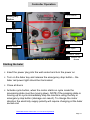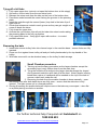
1
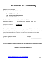
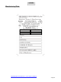
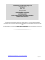
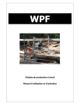
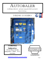
AUTOBALER Operation and Maintenance Manual HK140 Combo Trethewey Industries 14 Carl Baer Circuit Deepwater NSW 2371 Australia Customer Service Number: 1800 888 403 TiMan006 HK140 Combo Rev 2 7 June 2010 Op Manual Page 1 Declaration of Conformity Application of EC Directive(s) Standard(s) to which Conformity is declared: MD: 98/37/EC Machinery Directive LVD: 73/23/EEC Low Voltage Directive EMC: 89/336/EEC EMC Directive Manufacture’s Name: Trethewey Industries Pty Ltd Manufacture’s Address: 14 Carl Baer Circuit, Deepwater NSW 2371 Description of Equipment: AUTOBALER® Model: HK 140 Combo Trethewey Industries Pty Ltd hereby declares that the product(s) specified above conform to the above directive(s) and Standard(s). This apparatus must not be put into service until the equipment into which it is incorporated has been declared in conformity with the essential requirements of the relevant EC directives. Full Name: Reginald Trethewey Position: Signature: ____________________ Director Date: ____________________ For and on behalf of Trethewey Industries Pty Ltd, Deepwater NSW, Australia Compliance Compliance assessed and approved by: TiMan006 HK140 Combo Rev 2 7 June 2010 Op Manual Page 2 Owners Manual Thank you for choosing Autobaler® HK140 Combo. It is our wish that you remain very happy with the performance and service given by your baler and our service backup staff. For operating this baler properly, please take time to read this manual thoroughly before starting operating your baler. Keep this manual handy for future reference. The information contained in this manual is basic information. If you require information over and above what is supplied in this manual, please contact the Autobaler® service hotline on 1800 888 403. Model covered by this manual Autobaler HK140C-3I2 Combo Autobaler HK 14C-3I2-T Combo Note Training is required to operate Autobalers. Training is required to service Autobalers. Autobalers are protected by International Patents and Patent Applications. TiMan006 HK140 Combo Rev 2 7 June 2010 Op Manual Page 3 OPERATION AND MAINTENANCE MANUAL USER MANUAL SPECIFICATION MANUAL MACHINE - AUTOBALER® and CYBERSMART CONTROLLER MODEL - HK140 Combo AUTOBALER SERIAL NUMBER: ________________ CONTROLLER: Cyber Micro Serial No: ______________ Name and Address of Manufacturer Trethewey Industries 14 Carl Baer Circuit Deepwater NSW 2371 Australia Please Read This Document before Operating the Machinery TiMan006 HK140 Combo Rev 2 7 June 2010 Op Manual Page 4 WARRANTY To maintain warranty the baler must be serviced in accordance with the manufactures recommendations outlined in chapter 9 and the service booklet. The firm guarantees the machine described herby, has been designed in compliance with all regulations in force, in particular, safety and health regulations. The machine has undergone successful testing. (See test certificate enclosed.) The warranty covers a period of 12 months. It does not cover electrical motors and tools. Extended warranty to 5 years is available The purchaser is entitled to the replacement of faulty parts. Shipping and packing costs are at the purchaser’s expense. The warranty does not cover damage caused by: Falls or careless handling of the machine, incorrect operation, and non-compliance with the maintenance rules. Any tampering with the machine, especially with its safety devices automatically voids warranty. The manufacturer will be freed from any responsibility. No claim for damages shall be accepted in cases where the machine has been laying idle for a long period of time. The serial number on the machine is a main reference for the warranty, instructions manual, after sale service and identifies the machine in case of need. Serial Number must be quoted in all correspondence. NOTES The machines are manufactured in compliance with the accident prevention rules in force. The machines strictly comply with the instructions contained in the manual to obtain the best performance from the machines. Strict compliance with the rules contained will ensure optimum results and avoid any inconvenience caused by the non-compliance of operation and maintenance instructions. To avoid contacting the manufacture for problems which can be easily solved, closely follow the instructions given below. If after having strictly complied with the instructions given, the buyer still needs the help of our technical assistance service, he must supply all the technical indications necessary to determine correctly. This will enable our technical assistance service to intervene quickly and efficiently on the machine Copies of the instructions manual may be requested upon indication of the machine serial number. TiMan006 HK140 Combo Rev 2 7 June 2010 Op Manual Page 5 IMPORTANT Upon delivery of the machine, the consumer must make sure that all the devices indicated in the paragraph on the safety manual are present and working correctly. Furthermore, he must mount in conformity with the instructions indicated the devises which are not mounted at the time of delivery to facilitate transport. When ordering spare parts it is necessary to state: Machine Model Serial Number and Year of Manufacture Item Reference Number Without serial number, no spare parts will be delivered! DEFINITIONS User: The person body or company who has brought or rented the machine and intends to employ the users trained and inducted in the safe use & operation. Operator: The physical person authorised by the user or a representative of Trethewey Industries to operate the machine after having been suitably trained on the use and specific risks of the machine. Authorised Person: The skilled person authorised by the user to carry out maintained or setting up operation on the machine Dangerous Zone: Any person who finds himself in a dangerous zone as marked on the baler either entirely or partially. PURPOSE OF MACHINE This machine has been designed to be mainly used in smaller supermarkets or similar applications. This machine has been designed for the compaction of cardboard, paper and similar fibourous materials. Use differing from the above is to be considered inappropriate and prohibited. The machine operator must be trained and informed of risks and must have the instruction manual at his disposal The operator must not work with any guards or safety devices inoperative or missing. The baler must not be operated. RISKS During the pressing phase, the operator must never put hands or use tools in the compaction area. TiMan006 HK140 Combo Rev 2 7 June 2010 Op Manual Page 6 Copyright Manual INDEX 1) SCOPE Background Manufacturing plate Compliance certificates Test reports Risk Assessment 9 10 11 - 14 15 - 18 19 2) WARNINGS 20 3) COPY OF WARNING NOTICES 21- 22 4) LIFTING AND HANDLING INSTRUCTIONS 23 Baler specifications Removing the baler off the pallet Positioning the baler on the pallet 24 25 25 5) PRE- INSTALLATION INSTRUCTIONS Pre – Installation Check Safety Commissioning of the baler Controller Operation 26 - 27 27 - 28 29 - 30 31 6) OPERATING PROCEDURES Twining up the baler Tying off a full bale Removing the bale 32 32 33 TiMan006 HK140 Combo Rev 2 7 June 2010 Op Manual Page 7 7) TRAINING PROCEDURES Safety Procedure for Training Machine Operation Trainee Particulars Trainee Questionnaires Safety Sheet 34 34 35 - 36 37 38 8) SETTING AND MAINTENANCE Maintenance Machine Cleaning Servicing – Hydraulics Lubrication guide Safety checklist 9) MAINTENANCE INSTRUCTIONS 39 40 41 - 42 43 44 - 45 46 10) MAINTENANCE INTERVALS AND LUBRICANTS Oils and Lubricants Specifications Material Safety Data Sheets 47 48 - 49 50 - 55 11) FAULT FINDING PROCEDURE 56 - 57 12) PARTS LIST 58 13) FLOOR PLAN 59 - 60 14) CybaMicro® OPERATORS MANUAL 61 TiMan006 HK140 Combo Rev 2 7 June 2010 Op Manual Page 8 CHAPTER 1 SCOPE Background Autobalers are an extremely versatile machine being able to compact a large range of materials i.e.; paper, cardboard, plastics and most other compactable materials. Autobalers come in a ten model range to suit the customers own particular requirements, models range from 80kg to 500+kg capacity. Autobalers are a quality machine offering unparalleled safety and amazing efficiency achieving huge labour savings. Trethewey Industries have vast experience in the manufacture of quality baling machines, having produced in excess of 5000 agriculture baling machines. Five years ago Trethewey’s developed the Autobaler for commercial use, in particular to be used in Supermarkets and Recyclers. Trethewey Industries are situated on the New England Hwy at Deepwater NSW. Trethewey Industries location is ideal for servicing our national markets. Trethewey Industries focus is to develop machines which totally satisfy our customer requirements in performance, quality, service, economy and safety. Autobalers were developed to give the maximum efficiency and safety possible. Autobalers are designed for loose materials and are not recommended for solid materials i.e. hard wooden or metallic objects as these may cause machine damage. The manufacturers are happy to assess your needs and make recommendations and give assurances on the type of baler which best suits your Requirements: Autobalers are built to comply with the highest national and international standards as follows. Autobalers® are protected by International Patents and Patent Applications. TiMan006 HK140 Combo Rev 2 7 June 2010 Op Manual Page 9 SCOPE Manufacturing Plate: TiMan006 HK140 Combo Rev 2 7 June 2010 Op Manual Page 10 DECLARATION OF CONFORMITY 98/37/EC Machinery Directive 73/23/EEC Low Voltage Directive 89/336/EEC EMC Directive Name of manufacturer or supplier Trethewey Industries Pty Ltd Full postal address including country of origin 14 Carl Baer Circuit, Deepwater NSW 2371, Australia Description of product Paper & Cardboard Baling Machine Name, type or model, batch or serial number Type - Autobaler Make - Trethewey Industries Pty Ltd Model – HK140 Combo Location – 14 Carl Baer Circuit, Deepwater, NSW 2371 Australia Supply - 415V ac 3- Serial No: _____________________ Mass Weight - __________________ Standards used, including number, title, issue date and other relative documents See attached sheets Place of issue Name of authorised representative: ______________________________________ Position of authorised representative: ____________________________________ Full postal address if different from manufacturers Declaration I declare that as the authorised representative, the above information in relation to the supply / manufacture of this product, is in conformity with the stated standards and other related documents following the provisions of the above Directives and their amendments. Signature of authorised representative _____________________Date_________ TiMan006 HK140 Combo Rev 2 7 June 2010 Op Manual Page 11 Trethewey Industries Autobaler® EN ISO 12100-1 Safety of machinery - Basic concepts, general principles for design – Part 1 Basic terminology, methodology EN ISO 12100-2 Safety of machinery - Basic concepts, general principles for design – Part 2 Technical principles and specifications EN 294 Safety of machinery Safety distances to prevent danger zones being reached by the upper limbs EN 349 Safety of machinery Minimum gaps to avoid crushing of parts of the human body EN 418 Safety of machinery - Emergency ‘stop’ equipment, functional aspects Principles for design EN 811 Safety of machinery Safety distances to prevent danger zones being reached by the lower limbs EN 953 Safety of machinery - Guards General requirements for the design and construction of fixed and movable guards EN 954-1 Safety of machinery - Control systems - Part 1 General principles for design EN 982 Safety of machinery Safety requirements for fluid power systems and their components Hydraulics EN 1037 Safety of machinery Prevention of unexpected start-up EN 1050 Safety of machinery Principles of risk assessment EN 1088 Safety of machinery - Interlocking devices associated with guards Principles for design and selection EN 60204-1 Electrical - equipment of machines Part 1 General requirements AS 4024.1 Electrical Equipment TiMan006 HK140 Combo Rev 2 7 June 2010 Op Manual Page 12 Trethewey Industries Pty Ltd 14 Carl Baer Circuit Deepwater NSW 2371 20 August 2008 ASSESSMENT REPORT AUTOBALER® FOR COMPLIANCE WITH MACHINERY DIRECTIVE 98/37/EC THIS REPORT IS PREPARED BY RISKPLANT CONSULTANTS PTY LTD FOR RISK MANAGEMENT PURPOSES, AND ITS CONTENTS ARE PROVIDED EXPRESSLY FOR THE NAMED CLIENT FOR ITS OWN USE NO RESPONSIBILITY IS ACCEPTED FOR THE USE OF, OR RELIANCE UPON THIS REPORT, IN WHOLE OR IN PART, BY ANY THIRD PARTY. TiMan006 HK140 Combo Rev 2 7 June 2010 Op Manual Page 13 INSPECTION & ASSESSMENT METHODS EN 292 Safety of machinery - basic concepts, general principle for design EN 1050 Safety of machinery - Principles of risk assessment EN 418 Safety of machinery - Emergency ‘stop’ equipment, functional aspects EN 954.1 Safety of machinery -Safety related parts of control systems EN 1088 safety of machinery - Interlocking devices associated with guards EN 294 Safety of machinery - safety distances to prevent danger zones being reached by the upper limbs EN 60204 Safety of machinery - Electrical equipment of industrial machines TiMan006 HK140 Combo Rev 2 7 June 2010 Op Manual Page 14 Baler Test Report Comprehensive Autobaler® Test Report Date: Serial No: Testing Officer: Electrical Test Performed By: Noise Emission Test: Hydraulic Test: Autobaler® Quality and Reliability Test Full Mechanical Test Test Report No: Testing Officer: Operational Test Report No: Testing Officer: Lubrication Test Report No: Testing Officer: Testing Officer: Signature: TiMan006 HK140 Combo Rev 2 7 June 2010 Op Manual Page 15 Hydraulic Pressure and Performance Test “Report on Safety and Hydraulic Performance” This report is suitable for pressure systems below 2500 psi. System Pressure Required: System Pressure on Test: System Pressure Spikes: Pressure Switch Firing Range: Pressure Switch Firing Test: Hydraulic Delivery Hose Rating: Fluid Type and Grade: Hydraulic 32 Grade Cylinder Brand and Type: Duration of Cycle Test: Date: Inspector: Signature: TiMan006 HK140 Combo Rev 2 7 June 2010 Op Manual Page 16 Noise Emission Test Report Baler Noise Emission report - the test done from five positions:- a. From each side at a distance of 1m from the machine b. At a distance of 1m above the machine Decibels monitor type and number: Tenma 72.6604 Test one metre from front: Test one metre from left side: Test one metre from right side: Test one metre from back: Test one metre above machine: Injury precautions required: Ear Protection Must be worn if noise exceed 85 DB Date of Inspection: Inspection No: Inspector: Signed: TiMan006 HK140 Combo Rev 2 7 June 2010 Op Manual Page 17 Earth Bonding and Electrical Test Report on Safety Inspection and Testing of Electrical Equipment This report is suitable for class 1 protectively earthed 3 phase 415V equipment. The test has been carried out in accordance with AS/NZS 3760, with the following electrical and visual inspections: 500V Insulation Resistance Tests Active 1 to earth: Active 2 to earth: Active 3 to earth: Pass Pass Pass Fail Fail Fail Earthing continuity: Pass Fail Flexible supply cord: External visual inspection of plug connection: Visual inspection of cord termination to equipment: Pass Fail Pass Fail Visual inspection of wire termination in electric motor terminal housing: Pass Fail Date: Inspection number: Inspector: Inspector registration number: Signed: ………………………………………………………………………… TiMan006 HK140 Combo Rev 2 7 June 2010 Op Manual Page 18 Trethewey Industries New Machinery Hazard Identification Assessment and Control Description: Autobaler Model: HK140 Combo Brand: Trethewey Industries Developed in Co-operation between AWISA and Australian Chamber of Manufacturers This program is based upon the Australian WorkSafe Standard for Plant NOHSC: 1010-1994 Item No. Hazard Identification Hazard Assessment A Entanglement Nil C Cutting, stabbing, puncturing Nil D Shearing Nil E High Temperature Nil F Striking Nil G Crushing Nil H Electrical Low O Other hazards, noise dust. Nil TiMan006 HK140 Combo Rev 2 7 June 2010 Op Manual Risk control Strategies Page 19 CHAPTER 2 Warning Equipment Service Hazard Unauthorized service or adjustment of this machine can cause serious injury. Only those qualified and approved by the manufacturer and make adjustments or perform service on this machine. Operators must be trained in the safe operation of this machine. Do not alter, modify or adjust this machine if untrained to do so. Service technicians: When servicing, adjusting or repairing this machine, basic safety equipment must be worn i.e. compliant boots, safety glasses, long sleeve clothing etc. Three areas of hazard exist when servicing or repairing this machine that service technicians must be aware of. Hazard 1: If the pressing plate is fully up and hydraulic hoses are released the pressing plate can come down quickly causing a possible striking injury- always support the pressing plate with a prop or chain. Hazard 2: The baler system is controlled by a Starlogixs controller. This controller contains dangerous high voltage- this voltage resides at three points. 1. At the controller all components within have dangerous voltage. 2. At the door limit switch this switch has mains voltage. 3. At the pressure switch situated in the hydraulic system this is mains voltage. All electrical work must be performed by a qualified electrician. Baler must not be operated if fault or damage is detected in the system. Carefully follow the manufacturer’s instructions for personal safety with the above issues TiMan006 HK140 Combo Rev 2 7 June 2010 Op Manual Page 20 CHAPTER 3 Warnings 1) Autobalers must only be operated by qualified people 2) Only qualified people to service or repair Autobalers 3) Before servicing or repair familiarise yourself with the relevant instruction manual 4) The Autobaler must not be used in a manner contrary to the manufacturer’s instructions. 5) Prior to moving the Autobaler ensure the pressing plate is in the down position and the fork lift capacity is at least 1.0 tonne. 6) On installation or repair ensure the machine is effectively earthed. (All electrical work to be carried out by qualified electrician). 7) Always disconnect the electrical supply before servicing or repair due to electrical hazard Failure to observe Safety Precautions could lead to severe injury. We recommend operators using the following personal protective equipment:- 1. Safety glasses 2. Safety shoes 3. Safety gloves TiMan006 HK140 Combo Rev 2 7 June 2010 Op Manual Page 21 COPY OF WARNING NOTICES ON MACHINE (INCLUDING NAMEPLATE) Will Void Warranty NOTICE NOTICE TiMan006 HK140 Combo Rev 2 7 June 2010 Op Manual Page 22 CHAPTER 4 Lifting and Handling Instructions of the baler TiMan006 HK140 Combo Rev 2 7 June 2010 Op Manual Page 23 HK140 Combo Autobaler® Transport height 2030 Operating width 1775 Depth 930 Compaction chamber Large ......................700(D) x 900(W) x 880(H) Small.......................250(D) x 800(W) x 900(H) Bale weight Cardboard..............100-140kg Plastic.....................40- 60kgs Cycle time 30 seconds Compaction force 7000kg Motor 3 phase 2kw Baler mass 625kg Shipping weight 725kg TiMan006 HK140 Combo Rev 2 7 June 2010 Op Manual Page 24 The following procedure is for the safe transportation and movement of the Autobaler® 1. REMOVING THE AUTOBALER FROM THE PALLET a. Unwrap and cut metal strapping b. Insert the fork lift tines through the slots beneath the Baler. Ensure that the fork lift tines are fully through. c. Lift the baler no more than 80mm off the pallet, check again to ensure sufficient tine protrusion. d. Lift sufficiently i.e. 50mm to clear the pallet, slide the pallet beneath the baler with caution e. With tines beneath the Baler, always move: close as possible to the floor at idle speed only in reverse to ensure good vision Note: When transporting the Autobaler where lifting on a truck is required a. When baler is transported, pressing plate MUST be in the down position!!! b. Always transport on a solid hardwood pallet c. Never lift the baler more than 300mm unless on a pallet, as the baler could slip off the tines (metal to metal) d. If lifting the baler from beneath the baler base, fasten the baler to the fork mask using strap or chain e. When lifting the baler more than 300mm, always be on level ground and never transport the baler in an elevated position f. When transporting or moving the baler on the fork lift, always travel in reverse to ensure good vision g. Safety Equipment: Compliant safety boots, high visibility vest, hearing protection, eye protection and head protection if required. 2. POSITIONING THE AUTOBALER ON THE PALLET The baler is lifted beneath the lower front door (NEVER LIFT BEYOND THE FORK LIFT TRUCK’S CAPACITY) a. Before attempting to lift, ensure that the fork lift tines are fully through. Dismount the fork lift and check to ensure fork lift tines are fully inserted b. Lift the baler 200mm off the floor c. Slide the pallet equally under the baler from the side, ensure that the pallet can be lifted from the front d. Lower the baler gently onto the pallet and strap the baler to the pallet if transporting a long distance 3. POSITIONING THE BALER ON THE TRUCK When loading the baler for its final destination, the baler is to be loaded in such a way so as to facilitate the removal at the customers’ end, i.e. if the baler is to be unloaded using a forklift truck, the pallet will need to be situated to facilitate this but if the baler is to be unloaded using a pallet jack, then the pallet containing the baler needs to be situated to facilitate this (which would be a 90 degrees) TiMan006 HK140 Combo Rev 2 7 June 2010 Op Manual Page 25 CHAPTER 5 PRE-INSTALLATION INSTRUCTIONS Trethewey Industries Autobalers undergo a thorough quality check before they are dispatched from the factory. This ensures that they are all in perfect operational order. Due to varying conditions experienced during the transport process, the Autobalers require a pre-installation and pre-commissioning check. N.B Installation and Commissioning of the AutoBaler should be carried out by approved personnel with trainer accreditation. Pre-Commissioning & Assembly Check Remove all wrapping from the Autobaler, cutting metal straps attaching the Autobaler to disposable pallet. Open doors and remove twine and bale trolley. Use a fork lift to remove the Autobaler from pallet, re-locate Autobaler to site chosen for use. Assess site for obvious that the chosen site may present a hazardous situation, make the client aware of the potential danger and suggest an alternative location. When the Autobaler is satisfactorily located, check for obvious damage from transport and handling. This check should include such items as: Damaged or severed power leads & safety switches Bent or twisted cowling Check the Autobaler for moisture contamination: The manufacturer recommends that Autobalers are not to be transported in a manner that could cause water contamination to the electric’s and the electronics. If water contamination has occurred, the Autobaler should not be connected to the power supply until the installer is fully satisfied that the moisture risk no longer exists. In case of severe water contamination, dismantling of the following may be required to allow evaporation of the trapped moisture: Motor junction box Solenoid valve coils Electronic Controller Unit, if contamination is suspected in this unit, contact the manufacturer, Starlogixs 02 67 345 262 If moisture is present, allow to dry thoroughly. If excessive water contamination has occurred to the controller unit, it may require replacing with a dry unit. In many cases, this is the best option. Moisture in sensitive electronic components may take long periods to dry thoroughly. Attempting a start-up with a moist unit may result in serious damage to the Controller Unit. TiMan006 HK140 Combo Rev 2 7 June 2010 Op Manual Page 26 CHECK THE ELECTRIC’S Check the plug unit for damage or loose wires Check the lead from the plug to the controller unit for damage, if in doubt, use an appropriate multimeter Check the power connection units at the bottom of the controller unit for firm undamaged connections Check the power entry to the motor junction box, if damaged or a fault is suspected, call a qualified electrician Check the wall socket, do not connect to a wall socket (point) that shows damage or is in poor repair CHECK HYDRAULIC SYSTEM Check fluid level in the reservoir. The oil should be showing on the dip stick. If fluid is not shown, add 32-grade hydraulic fluid until presence is indicated. Caution - Do Not Over Fill. Ensure cylinders are fully closed and do not exceed the levels on the site glass or dip stick. Check oil tank for transport damage Check hydraulic hoses, if damaged, replace. (check with manufacturer for correct hose type) Check for obvious leaks, and systematically check tightness of all fittings. CHECK ROTATION OF MOTOR Plug into power source and turn on, turn Autobaler key onto the “on” position, release Emergency Stop by turning clockwise if necessary. Immediately stop by pressing “Emergency Stop”, and view rotation of motor. If it is not running clockwise, the polarity can be changed see CybaMicro® Manual Chapter 14, contact a qualified electrician AUTOBALER LOCATION - SAFETY A. Location of Autobaler: a. Never place the Autobaler near any landings or elevated loading docks, unless these areas have the appropriate safety arrangements and approvals. b. Never place the Autobaler under a man hole, air conditioner, refrigeration unit, light or any position where a service technician may have occasion to work above the machine. c. Never place the Autobaler on a loading dock, close to the edge or the above landings edge. d. Never place the Autobaler in a position where unauthorised persons have access. e. Always consult an OH&S officer. B. Area of Operation: a. Ensure that baler trolley is stored in a position away from the operator’s passageway. b. Ensure that electric lead is not in a hazardous position and is not left lying on the floor, particularly if there is a chance of water being on the floor. TiMan006 HK140 Combo Rev 2 7 June 2010 Op Manual Page 27 C. Operation of Autobaler: a. Always keep hands and arms out of the Autobaler during operation. b. Always, when entering the pressing chamber for re-stringing etc, wait until the motor stops and turn the key to the “Off” position. c. Always load evenly with materials or baler may shutdown, requiring a serviceman to attend. d. When ejecting full bales, never pull on the twine in such a manner that if the twine breaks, or the knot fails, a fall will result which may cause an injury. e. Always use the baler trolley, pallet jack or fork lift to relocate full bales. f. Always be aware of door rebound when opening top or bottom doors, always stand to the side. g. Never attempt to operate Autobaler with the front door open. h. Never attempt to clean, lubricate or work in the vicinity of the cylinders during operation. SAFETY CLOTHING / FOOTWEAR a. During assembly, location and operation of the baler, safety compliant footwear must be worn. b. Firm fitting work place compliant clothing must be worn. c. Safety compliant work place gloves, hearing protection and eye protection must be worn. GENERAL Always remove Autobaler key when machine is not in operation, or is unattended. Trethewey Industries recommend that the following checks be carried out:WEEKLY a. b. c. d. e. Check safety guards around moving parts. Are they in place? Are they damaged? Check Autobaler key switch, is it functional and in good order? Check emergency stop button, is it functional and in good order? Check power lead, is it undamaged? Is it clear of any moisture? Check Autobaler response to opening top door. Opening more then 50mm (approx 2 inches) should cause the machine to cease cycling. IF ANY OF THE ABOVE CHECKS REVEAL DAMAGE OR MALFUNCTION, THE MACHINE SHOULD BE SHUT DOWN AND THE KEY REMOVED UNTIL THE FAULT IS REPAIRED. PREVENTATIVE MAINTENANCE: a. Every 4 months, or every 500 bale’s the operation of the Autobaler should be checked by a qualified person to ensure that all safety features are functioning correctly and are undamaged. b. From time to time, a qualified electrician should inspect all power leads and electrical contacts. TiMan006 HK140 Combo Rev 2 7 June 2010 Op Manual Page 28 COMMISSIONING NEW AUTOBALER This is the stage where a fully functional Autobaler is handed over for use by the end-users. At the conclusion of this commissioning, the installer must be satisfied that the Autobaler will perform as specified, and that the end-users are fully conversant with the operation and the safety guidelines. A. Initially, the installer must be satisfied that: The Autobaler is complete, as specified by the manufacturer The Autobaler is the specific model, as requested The power source is as specified All accessories and attachments are as requested All functions of the Autobaler operate correctly The motor rotates in a clockwise direction The hydraulic oil reservoir is full There are no hydraulic oil leaks There is no damage to any safety barriers There are no safety concerns regarding the location of the Autobaler A qualified electrician has checked the power source, lead and electrical contacts B. The installer must now: Ensure that one, or more, of the end-users are completely trained in the safe use of the Autobaler Ensure that those trained are fully aware of safety procedures associated with the safe use of the Autobaler carry out a full training session, incorporating these factors C. At the completion of the training session, the installer must: Complete the “Job Completion” form, detailing precisely what was delivered and accepted by the end-user Complete the “Training & Trainee Particulars” forms, detailing the names of those who attended the training session. These persons will be sent a certificate stating that they are competent to operate the particular Autobaler, as well as have the overall knowledge to train others in its operation D. Training the end-users should be carried out as follows: Ensure that the person who has ultimate responsibility for the operation of the Autobaler is amongst those to be trained initially i.e. Head Storeman or Cleaner. Carry out the training, using the end-users as much as possible, from the stage of inserting the twine initially, to the removal of a full bale At all stages of the training process, make sure that those being trained are fully aware of the safety aspects associated with the operation of the Autobaler. TiMan006 HK140 Combo Rev 2 7 June 2010 Op Manual Page 29 E. Training is to be conducted as follows: Affixing of twine to cup head bolts, explaining need for double knots Placement of twine under lugs on the base of the pressing chamber Allowance for length of twine Fixing of twine from rear wall, under lugs, up the inside of bottom door and fixed on handle/twine tab. Closing of front doors and explaining of safety features i.e. Autobaler key, emergency stop button and door opening cut out (magnetic door switch) Demonstration of operation of Autobaler with no material in pressing chamber Explanation of “bale full” signals Demonstration on how to “tidy up” final bale Explanation on why bottom door should never be opened during baling process Tying of bale Opening of bottom door, with emphasis on possibility of rebound Importance of fitted safety chains Placement of bale trolley and description of bale removal trolley Removal of full bale, with emphasis on need for manual assistance and care to be taken TiMan006 HK140 Combo Rev 2 7 June 2010 Op Manual Page 30 Controller Operation Emergency Button Cycle button Power Key Bale Full Display Power Flash Door Open Hydraulic Fault* *Only on ‘Tilt’ models Starting the baler Insert the power plug into the wall socket and turn the power on Turn on the baler key and release the emergency stop button – the baler red power light should be illuminated Close all doors Activate cycle button, when the motor starts on cycle mode the processing plate must be moving down. NOTE if the pressing plate is moving up on cycle immediately stop the machine using the key or emergency stop button (damage can result). To change the motor direction the electricity supply polarity will require changing at the baler socket end. TiMan006 HK140 Combo Rev 2 7 June 2010 Op Manual Page 31 Chapter 6 Baler Operating Procedures Twining up the large chamber: 1. Fully open the main chamber door. 2. Cut two pieces of twine at 4metres. 3. Tie a double loop in one end of each twine. (See illustration 1) Illustration 1 4. Hook each end of the twines over the twine hooks on the rear wall. (See illustration 2) Illustration 2 Illustration 3 5. Position each twine beneath the twine retainers on the base inside the chamber. (See illustration 3) 6. Gently holding both loose twine ends close & latch the bottom door. 7. Bring twines up the inside of the closed bottom door & fasten on twine tabs on lower rail of bottom door – rotate twines around the tab & out through the slot. (See illustration 4) Illustration 4 8. Close the main lower door. 9. Load material through the opened top door: place material that is longer than the machine width lengthways towards the back. 10. Continue to load & cycle the baler – remember that a tidy bale will be a result of careful placement of materials – do not over fill the loading chamber – less material cycled more often gives the best results. NOTE: if baler is loaded unevenly or with bulky items, cylinders will become uneven resulting in the shutdown of the baler & ‘Tilt will appear on the controller. A qualified serviceman will then need to attend to the baler. 11. When a full bale is achieved the pressing plate will not return up automatically & a full bale reading will be displayed on the digital reader – a full bale will have the pressing plate marginally below the top of the bottom door. TiMan006 HK140 Combo Rev 2 7 June 2010 Op Manual Page 32 Tying off a full bale 1. 2. 3. 4. 5. 6. 7. 8. 9. Fully open upper door (note do not open the bottom door at this stage) Unhook or cut the twine from the rear twine hook. Release the twine ends from the tabs on the front of the bottom door. Pass these ends beneath the cross & along the grooves in the pressing plate. Insert the ends through the second (lower) loop tied in the twine & pull tight & tie off. Check that twines are central in each groove as they can get caught on a corner & break the twine. Fully close the upper door. Activate the cycle button, this will put the baler into retract mode raising the pressing plate to the fully up position Fully open both doors – firmly grip & open with caution – to control possible rebound. Removing the bale 1. Insert bale remove trolley forks into channel ways in the machine base – ensure forks are fully inserted. 2. Place one foot against lower trolley rail and pull trolley backwards by the top handle of the trolley. 3. With bale removed it can be wheeled away on the trolley for bale storage Small Chamber procedure 1. Twining up has the same procedure as the larger chamber except the secondary loop is only 60mm down from the main loop. 2. Tying the full bale off is similar to the larger chamber except the looped end is passed under the rail & tied off at the front. Note if plastic is being baled then a piece of cardboard will be needed on the top of the bale to ensure a clear track under the rail. 3. Removing the bale from the smaller chamber is done manually – open the bottom door after both hatch doors are fully open – ensure that the side door is fully opened. The bale comes out in a forward position. 4. Storing & handling the smaller bales will require care or the bale may come apart – store flat on a pallet placing one bale on another. For further technical help if required call Autobaler® on 1800 888 403 TiMan006 HK140 Combo Rev 2 7 June 2010 Op Manual Page 33 Chapter 7 Training Procedures Safety Procedure for Training 1. 2. 3. 4. 5. 6. 7. 8. 9. Autobaler location Bale trolley location, store trolley away to prevent trip hazard or injury. Twine cage correctly attached and twine placed in cage. No reaching into baler No standing or climbing on the baler Turn the baler off when unattended Care and position when removing bale – use of safety chains Importance of reading and observing all safety instructions Bale location in approved designated area. Point out safety devices: Emergency stop button Key switch Bottom doors Safety chains Machine operation 1. Motor rotation check. To test, press retract button, if the pressing plate goes up, rotation is correct. 2. Locate twine, pass twine through eyelet near top right corner. 3. Initial stringing, as outlined in Operating the baler:- Stringing 4. Close bottom door ensuring safety chains are in position. 5. Open top door. 6. Place flat cardboard in base prior to loading. 7. Load flattened material evenly until chamber is within 200mm of full. 8. Close top door. 9. Press cycle button. 10. Repeat process until the bale full red light illuminates. 11. Open top and bottom doors with pressing plate in down position. 12. Pull twine across from rear to front passing underneath the cross support bar, pass end of twine through the looped end, tie of firmly. 13. Using trolley – eject bale. 14. Remove bale to storage area. 15. Restring baler TiMan006 HK140 Combo Rev 2 7 June 2010 Op Manual Page 34 Autobaler Trainee Particulars (Kit) Company: ……………………………… Address: ………………………………… ………………………………… ………………………………… Trainee Name: …………………………… (Print Clearly in Capitals) Autobaler Model Trained To Use: ……………………… I..................................................... . (Trainer) witnessed the competency of …………………………………… In the safe competent use of the Autobaler Model……………………… and I received a copy of the Training Manual. I hereby validate this assessment. Signed (Trainer) ………………………….. Date …………………. Signed (Trainee) ………………………….. Date …………………. Special Comments ……………………………………………………………………………………… ……………………………………………………………………………………… ……………………………………………………………………………………… …………………………………………………………………………… TiMan006 HK140 Combo Rev 2 7 June 2010 Op Manual Page 35 Autobaler Training Handout Person in Training Name: ...................................……………………..... Address: ................................................................. ................................................................. ................................................................. Phone No: ...................……………………………....... Employer: ..............................……………………........ Date of Training: ........................………………........… Name of Trainer: ............................……………........… Autobaler Model Trained To Use: ……………………… TiMan006 HK140 Combo Rev 2 7 June 2010 Op Manual Page 36 Trainee Exam Questions (Autobaler HK140 Combo Series) 1. If the baler is in a public access area and the baler will be unattended for a long period, what precaution for public safety should you take: a. Sit and watch the baler b. Remove the key c. Do nothing 2. What function does the cycle button have: a. General operation b. Cycles the baler c. Raises the pressing plate only 3. The purpose of the emergency stop button is: a. Decoration b. For emergency stopping c. No particular use 4. When twining the baler at what position should the pressing plate be? a. Right down b. Half way down c. Fully up 5. What is the purpose of the plastic tabs on the base (floor) of the baler? a. Decoration b. Place twine beneath c. Structural 6. The last 10 – 20% of the bale, how would you place flattened material? a. On its edge b. Any way c. Flat in the baler TiMan006 HK140 Combo Rev 2 7 June 2010 Op Manual Page 37 7. Tying of the finished bale should be done with the: a. Plate retracted b. Plate halfway down c. Plate fully down 8. Opening of the top door, I should: a. Open it the best I can b. It doesn’t matter c. Grip the handle firmly 8B. Opening the main chamber lower door: a. the best I can b. Jump out of the way c. Attach rebound chain and open with caution, supporting the door with the other hand 8C. Tying off the plastic baler: a. the best I can b. Place cardboard cap on the bale on the last stroke 9. Removing the bale in the main chamber: a. Pull as hard as I can on the twine b. Place the eject trolley’s fork fully into the baler grooves beneath the bale and pull carefully back and wheel removed bale to the store area c. The best I can 10. Where should the bale trolley be stored when not in use? a. in front of the baler b. to the side of the baler c. Anywhere 11. Really heavy object i.e. boxes of magazines etc. How should I load them into the baler? a. Over the bottom door in one large bundle b. Place in baler in small evenly distributed amounts c. The best I can TiMan006 HK140 Combo Rev 2 7 June 2010 Op Manual Page 38 12. If the baler operates with the top door open, I must: a. Continue as normal b. Shut the machine off, remove the key and place an ‘Out of Order’ sign on it c. Take care 13. Baler is full of cardboard, how can I know? a. No way of knowing b. Baler creaks c. Full bale show on the controller as cardbard full 14. Full plastic bale, how can I know? a. No way of knowing b. Baler creaks c. Full plastic shows on the controller 15. Twining the plastic chamber (small chamber) a. The best I can b. It doesn’t matter c. Same procedure as cardboard chamber 16. Was the knot test passed? Yes No TiMan006 HK140 Combo Rev 2 7 June 2010 Op Manual Page 39 SAFETY ESSENTIALS 1. Before commencing the baling process ensure that the bottom door is latched & safety chains installed correctly to prevent the door bursting open during process. 2. Never climb onto the baler from any side or reach in during operation or stand on elevated objects. 3. When removing the bale always use the provided eject trolley. 4. Always place the bale transport trolley centrally & fully inserted in the base channels. 5. On incline, chock bale trolley to prevent run away 6. Always use the safety knife for cutting twine. 7. To prevent strain injury, ensure that the doors and latches open freely – lubrication may be required 8. Remove key from baler if the baler is unattended in a public access area. 9. If there is a fault with the machine, it should be tagged out. Do not operate the machine. Contact 1800 888 403 for assistance 10. Operators must be trained by authorised representatives of Trethewey Industries and carry their Statement of Attainment Card as evidence of qualification. TiMan006 HK140 Combo Rev 2 7 June 2010 Op Manual Page 40 CHAPTER 8 SETTINGS AND MAINTENANCE SECTION MAINTENANCE DESCRIBED IN THIS MANUAL IS ONLY TO BE PREFORMED BY A TRETHEWEY INDUSTRIES APPROVED AND QUALIFIED REPRESENTATIVE. Always disconnect Electrical Supply before carrying out any repairs or servicing to the baler Maintenance Definition: - Scheduled periodic servicing. Preventative Maintenance: - A service provided at four monthly intervals. Average usage: - A baler producing up to 2 bales per day - recommended preventative maintenance period not to exceed four months and to be serviced according to the standard servicing schedule. High usage: - a baler producing more than 2 bales per day - recommended service period not to exceed three months and to be serviced according to the standard servicing schedule. Major Maintenance: - A serviced preformed every 12 months or every 660 bales and to be serviced according to the standard servicing schedule. A major service has the additional service elements. 1. Hydraulic Systems check / Power screw check (Depends on model) 2. Hydraulic Cylinder balance check / Transmission belt check Safety: - All service intervals to include a full safety check and report. TiMan006 HK140 Combo Rev 2 7 June 2010 Op Manual Page 41 MACHINE CLEANING To keep your baler in top working condition, frequent cleaning is required. POWER UNIT CLEANING Never attempt to service the power unit without first thoroughly cleaning the unit. - Note: Always disconnect the power socket from the power source plug before attempting any guard removal - Remove the key from the controller and attach an ‘in service’ note to the baler - Keeping the power unit clean will prevent overheating and system contamination NOTE: - Power unit must be cleared of accumulated material pieces on a regular basis to prevent overheating. CLEANING THE BALER To keep the baler in good appearance, we recommend the use a soft cloth. Remove any contamination of the inner chamber wall using a damp cloth, use only mild detergents. This will prevent bales from being difficult to remove when ejecting from chamber. NOTE: Never use petrol or mineral solvents to clean the machine as this may damage the paint. GENERAL HOUSE KEEPING Daily remove material build up around the baler, especially between the rear of the baler and the wall & the top of the pressing plate. A material build up creates a fire and vermin hazard. Keep the access area to the baler free of all materials to prevent a trip hazard and other OH&S concerns. TiMan006 HK140 Combo Rev 2 7 June 2010 Op Manual Page 42 SERVICING Service Period Every 3 months to 4 months depending on the baler classification (AVERAGE USAGE = Up to 2 bales per day) (HIGH USAGE = More that 2 bales per day) M/M = Major Maintenance every 12 months or every 660 bales Major Maintenance 1. Replacing the Oil Filter 2. Replace damaged hoses 3. Full Lubrication Guide 4. Door Adjustment Check 5. Safety Check List 6. Service Guide TiMan006 HK140 Combo Rev 2 7 June 2010 Op Manual Page 43 SERVICING HYDRAULICS It is recommended that the oil is tested annually to check for the following: - oil contamination - Oil damage from overheating - Water ingressions from high pressure cleaning The hydraulic system requires a filter change every third service – (Oil filter models only). The filter is situated on the hydraulic tank which is situated at the side or rear of the Autobaler (Oil filter models only) Filter Changing Procedure:a. Remove the three small studs on the tank, these are located on the top of the unit (see illustration1) b. Lift filter out of the unit (Note: the unit does not require removal from the tank) c. Replace the new filter taking care with the re-assembly making sure that the filter is the correct way up (see illustration 2) d. Ensure no contamination occurs, clean well before disassembly and re-assembly e. Tighten the filter unit lid down evenly f. Run the machine and check for oil leaks Illustration: 1 Illustration: 2 TiMan006 HK140 Combo Rev 2 7 June 2010 Op Manual Page 44 FULL LUBRICATION GUIDE (EACH MAINTENANCE PERIOD) Using KZD coupler (provided) grease all hinge and latch pivots ‘see Lubrication guide’. Lubricate ‘twine sensor’ unit at rear of baler Lightly grease internal pressing plate guides Lightly lubricate door latches using clear grease Lightly lubricate door hinges using clear grease Grease all latch & door hinge pivots Change oil filter cartridge under normal conditions every 2 years Check hydraulic fluid leveltop up only if required Lubricate all moving or sliding components using PBL spray lubricant RECOMMENDED LUBRICANTS Only lubricants recommended by the manufacturer are to be used in the Autobaler. Failure to use the recommended lubricants will result in voidance of the baler warranty. Autobalers have high pressure pivot points and therefore must only be lubricated with high pressure long life lubricants. HYDRAULIC OIL GREASE SPRAY LUBRICANT : : : CASTROL HYSPIN 32 GRADE MBL 8 PBL 3 SPRAY LUBE For further details and possible supply of the recommended lubricants, Please phone:TOLL FREE : 1800 888 403 OR 02 67 345 403 TiMan006 HK140 Combo Rev 2 7 June 2010 Op Manual Page 45 6. SAFETY CHECK LIST GOOD POOR ACTION TAKEN 1. Check top door operation, door must not open more than 30mm without activating safety switch, adjust if required 2. Check emergency switch 3. Check key operation 4. Check power leads for damage, placement etc 5. Check baler situation, ensure it is a safe and approved location do not place under manholes, walkways, elevated docks etc 7. Check twine placement, it must be situated to prevent tripping 8. Check upper and lower door catches for positive lock 9. Check safety chains are securely in place 10. Check all guarding, report, refit or correct if required 11. Report unsafe operator practices 12. Report other areas of safety concern 13. Check safety signage is in good order 14. Ensure that trolley is being stored for safe operation Electrics -Check wiring for damaged or lose unsaddled wiring. -Check power plug and point -Check electronics generally report or repair damaged or dangerous situations. Comments……………………………………………………………………………………… …………………………………………………………………………………………………… …………………………………………………………………………………………………… Controller -Check controller for correct function -Check for & report damage -Check all fittings to the controller for firm positive connection -check controller anchor screws Comments……………………………………………………………………………………… …………………………………………………………………………………………………… …………………………………………………………………………………………………… TiMan006 HK140 Combo Rev 2 7 June 2010 Op Manual Page 46 Structural -Thoroughly check for cracks or failed welds or any signs of fatigue or structural damage report -Check all bolts. -Check cylinder anchor lugs for fatigue Comments……………………………………………………………………………………… …………………………………………………………………………………………………… …………………………………………………………………………………………………… Top door -Check latch is functioning correctly -Adjust and lubricate latch -Lubricate hinges -Check top door limit switch is functioning correctly -Check coded switch that they enter centrally, adjust if required (illus16) Comments....................................................................................................................... ......................................................................................................................................... ......................................................................................................................................... Guarding - Check that mesh guards are secure and free of damage, repair or report Comments……………………………………………………………………………………… …………………………………………………………………………………………………… …………………………………………………………………………………………………… Bottom Door - Difficult to close, lubricate – check for wear Comments……………………………………………………………………………………… …………………………………………………………………………………………………… …………………………………………………………………………………………………… Signage - Report missing safety signage - Report damage signage Comments……………………………………………………………………………………… ………………………………………………………………………………………………........ ......................................................................................................................................... TiMan006 HK140 Combo Rev 2 7 June 2010 Op Manual Page 47 CHAPTER 9 MAINTENANCE INSTRUCTIONS This should include safe working procedures for carrying out all preventative maintenance and repairs. This should also include any special tool requirements for maintenance. 1. Servicing Procedure 2. Personal Safety Gear Required 3. Before Commencing a Service 4. Lubricants, Tools and Spares Required SERVICING PROCEDURE Before attending a service site, the following may be required: (1) Source from the baler owner or operators the followinga. when the internal services are due b. date and time suitable to carry out the service c. an accurate location of the baler d. whether site induction and training is required to enter the site e. what type of clothing and footwear are required f. machine type and serial number g. does the baler require attention i.e. repair / adjustment etc over and above a regular interval service, so that likely parts required can be taken (2) Personal Protective Equipment required a. a high visibility shirt or vest b. regulation safety glasses c. regulation footwear d. hearing protection e. hand cleaner f. towel roll (3) Before commencing the service a. isolate the power source from the machine b. clean the area to be working in c. remove the baler key and place an “out of service” sign if required d. remove the guards relevant to a service LUBRICANTS REQUIRED TO SERVICE AUTOBALERS 1. Tube of PBL (Pro-ma) long life grease 2. PBL or similar spray lubricant 3. 32 grade hydraulic oil, note: a minimum of 4 litres is required for top up purposes in a regular service. Sufficient oil should be carried for maintenance which requires an oil change. For a complete oil change, the following amounts are required:-HK140 Combo Series baler 6 litres A container or containers will be required to deposit the used baler oil. In the likely event of an oil spill, carry a sufficient amount of oil absorbent substance to ensure that the floor area is completely oil free on completion of the job. Used oil must be disposed of via an oil recycler or in a legal manner. TOOLS REQUIRED FOR A PREVENTATIVE MAINTENANCE 1. 2. 3. 4. Cartridge type grease gun Oil pump Oil funnel KZD needle nose coupler TiMan006 HK140 Combo Rev 2 7 June 2010 Op Manual Page 48 CHAPTER 10 MAINTENANCE INTERVALS AND LUBRICANTS (1) Service Intervals (2) Recommended Lubricants (3) Material Safety Data Sheet for Lubricants SERVICE INTERVALS Autobalers require regular maintenance intervals to ensure that they perform and operate safely, reliably and efficiently. Autobalers must be serviced by qualified service people who have been instructed in the service of Autobalers Autobalers must be serviced according to the service requirements as laid out in the maintenance manual supplied with each Autobaler. It is a requirement that when an Autobaler has an interval service that the appropriate service leaf be dated and filled out according to the service and signed by the service technician. It is recommended that a service interval not exceed 4 months or every 500 bales. Autobalers must be serviced within this period during the warranty period. An integral component of the service is a comprehensive safety check to ensure interlocks and all other safety devices and guards are in good safe working order. RECOMMENDED LUBRICANTS Recommended hydraulic oil AWH 32 Castrol Autobalers have high pressure pivot points which require high pressure grease, therefore it is recommended that only Pro-ma MBL grease be used in the service of Autobalers or grease with equivalent lubrication properties (see data sheet). If maintenance periods are exceeded or lubricants used which are outside the manufacturers recommendations, Autobaler warranty may be voided. DATA SHEET, PRO-MA MBL 8 GREASE Benefits of Use Performs within high and low temperature operating ranges Resists water and water washout Provides oxidation stability Protects against rust Protects against extreme pressure Works well with high loading or severe shock loading Extends lubrication periods Prevents excessive seal swelling TiMan006 HK140 Combo Rev 2 7 June 2010 Op Manual Page 49 The Base Grease Used in MBL Grease has the Following Specifications NLGI Grade……………………………………………………………….........2 Soap Type…………………………………………….....….Lithium-Complex Texture…………………………………………………........………..…Buttery Base oil viscosity CST at 40C………………………………………………………….………..148 CST at 100C……………………………………………………….....…….....14 SUS at 100F……………………………………………………….....……...767 SUS at 210F…........................................................................................75 Base oil viscosity index….........................................................................90 Dropping point C (F) (ASTM D 2265)………………......280 + C (500 + F) Penetration, mm/10 (ASTM D 217) Unworked ….......................................................................................... 280 Worked 60 Strokes ........................................................................…..... 285 Worked 100,000 strokes, % change…………………………………...... + 10 Trident probe viscosity (ASTM D 3232) 204C (400F), poises …………………………………………………....….. 15 Oil Separation (ASTM D 1742) 24 hr at 25C (77F), %………………………………………………….....…. 3 Lubrication life (ASTM D 3336), no.204 bearing 10,000 rpm, 163C (325F), hrs………………………………………......... 290 Oxidation stability (ASTM D 942) Pressure drop at 100hr, kPa (psi)…………………………………….....14 (2) Pressure drop at 500hr, kPa (psi)……………………………………...70 (10) Roll stability (ASTM D 1831) % penetration change.......................…...+ 10 Wheel bearing test (ASTM D 1263 modified: 60-9 pack 160C (325F) Leakage, g…………………………………………….………………………1.5 Load carrying properties: Timken load (ASTM D 2509,kg (lb)…………………………………….25 (55) 4-Ball EP test (ASTM D 2596) Load wear Index, kg………………………………………………………..…40 Weld point, kg………………………………………………………..……….250 4-Ball wear test (ASTM D 2266), 40 kg 1200rpm, 75C (167F), 1 hr. Wear scar diameter, mm….................................... 0.40 Ball-joint test (ASTM D 3428) Brine sensitivity (noise and wear)………………………………….......….Pass Torque stability………………………………………………………….…...Pass Water washout (ASTM D 1264), % at 80C (175F)............................... 4 Rust prevention (ASTM D 1743), ASTM rating….................................... 1 TiMan006 HK140 Combo Rev 2 7 June 2010 Op Manual Page 50 Low temperature torque (ASTM D 1478), -40C (-40F) Starting, G-cm……………………………………………………..……….13, 000 Running, G-cm……………………………………………………………….5, 000 Mobility (U.S. Steel method) Flow rate at -18C (0F), g/sec………………………………………………..0.5 Rubbers swell (GM method) 70hr at 100C (210F) Volume change, %……………………………………………………….…...+ 12 Handling These products contain petroleum oil, copper and lead particles: Do NOT store near heat, sparks or flame. Wash with soap and water after contact with skin. KEEP OUT OF REACH OF CHILDREN. A material Safety Sheet is available from Pro-Ma Systems. Warning Do NOT take internally. Harmful or fatal if swallowed. It contains copper, lead particles and hydrocarbons. If swallowed contact a doctor immediately. Wash hands after use. Medical advice Contains petroleum oil, copper and lead particles. If swallowed, do NOT induce vomiting. Call physician immediately. Available Sizes 450g - 2.5kg - 20kg - 60kg and 202.5kg TiMan006 HK140 Combo Rev 2 7 June 2010 Op Manual Page 51 Material Safety Data Sheet Product Name: SUPERDRAULIC RANGE Date Issued: 3 June 1997 Page : 1 IDENTIFICATION Use: General purpose hydraulic oil. Not classified as hazardous according to criteria of Worksafe Australia. Company: WESTERN OIL 1 COOMBES DR PENRITH UN No. Main Class Subsidiary Risk Poisons Schedule Hazchem Code CASE No. : : : : : : Not Not Not Not Not Not Assigned Assigned Assigned Allocated Assigned Relevant PRODUCT PROPERTIES Appearance & Odour: Clear and bright oily liquid. Mineral oil odour Chemical Reactivity: Stable. Reacts with oxidising agents Solubility in Water: Negligible Property Specific Gravity Melting Point Vapour Pressure IBP FEP Evaporation Rate Vap Dens (Air=l) Fire/Explosion Hazard Flash Point Autoignition % Volatiles LEL UEL Value 0.87 Not Available Expect<0. 0005 Typically 280 Not Available Not Available UOM - Temp 15 kPa deg C 20 >1 Typically>224 Typically>320 Not Available Expected 1 Typically 10 - deg C deg C %v/v %v/v PRODUCT INGREDIENTS Ingredient Highly refined mineral oil Complex mixture of additives Proportion High >99.4% Low < 0.6% Blending Method m/m m/m CAS No. TiMan006 HK140 Combo Rev 2 7 June 2010 Op Manual Page 52 Material Safety Data Sheet Product Name: Date Issued: SUPERDRAULIC RANGE 3 June 1997 Page : 2 HEALTH HAZARDS HEALTH EFFECTS Acute Swallowed Slightly toxic, may cause gastric irritation Eye Product may cause slight to moderate irritation to the eyes. Skin Mildly irritating to skin: Prolonged and repeated skin contact may cause dermatitis due to defatting effect. Inhaled Inhalation of the vapours (generated at elevated temperatures) or mists can cause irritation to the nose and throat. TiMan006 HK140 Combo Rev 2 7 June 2010 Op Manual Page 53 Material Safety Data Sheet Product Name: SUPERDRAULIC RANGE Date Issued: Page: 4 3 June 1997 FIRST AID Swallowed If swallowed, do NOT induce vomiting, seek medical advice. Eye If contact is made with eyes, flood eyes with plenty of water for 20 minutes. If irritation occurs seek medical advice. Skin Remove contaminated clothing and wash skin thoroughly with soap and water. Inhaled Remove affected person from contaminated area and seek medical advice. If not breathing, apply artificial respiration and seek urgent medical advice. Advice to Doctor PRECAUTIONS FOR USE Exposure Standards Worksafe Exposure Standard: - time weighted average (TWA) 5 mg/m3 (oil mist) short term exposure limit (STEL) l0mg/m3 (oil mist) TiMan006 HK140 Combo Rev 2 7 June 2010 Op Manual Page 54 Material Safety Data Sheet Product Name: SUPERDRAULIC RANGE Date Issued: 3 June 1997 Page : 3 Engineering Controls Special ventilation is not normally required due to the low volatility of the product at normal temperatures. However, in the operation of certain equipment or at elevated temperatures, mists or vapour may he generated and exhaust ventilation should he provided to maintain airborne concentration levels below the exposure standard or where no exposure standards allocated, as low as is reasonably practicable. Personal Protection Avoid contact with the skin and eyes, and avoid breathing vapours or mists. When exposure is likely, personal protective equipment in a combination appropriate to the degree and nature of exposure, should be selected from the following list:(1) (2) (3) (4) Eye PVC PVC PVC protection gloves apron and sleeves, or full PVC covering or rubber boots Where the concentration of vapour or mist is expected to approach the exposure limit, the following additional equipment is recommended:(1) Short elevated exposures, eg spillage - goggles and correct respiratory protection should be worn. NB. If the vapour/mist concentrations exceed the exposure limit by more than 10 times, air supplied apparatus should be used. (2) For prolonged elevated exposures - Full face air supplied or self contained breathing apparatus should be worn. CONTAMINATION If contamination occurs, change clothing and discard internally contaminated gloves and footwear. Launder contaminated clothing before reuse. Observe good personal hygiene. Eye wash fountains and safety showers should be available for emergency use. TiMan006 HK140 Combo Rev 2 7 June 2010 Op Manual Page 55 Material Safety Data Sheet Product Name: SUPERDRAULIC RANGE Date Issued: 3 June 1997 Page : 5 Personal Protection (-. continued) REFERENCES For detailed advice on Personal Protective equipment, refer to the following Australian Standards HB 9 (Handbook 9) AS 1337 AS 1715 AS 1716 Manual of industrial personal protection. Eye protectors for industrial applications. Selection, use and maintenance of respiratory protective devices. Respiratory protective devices. Flammability Combustible liquid, will not burn unless preheated Refer to AS 1940 - Storage and handling of flammable and combustible liquids and AS 2865 - Safe working in a confined space, for more specific information on these subjects. SAFE HANDLING INFORMATION Storage & Transport Classified as a class C2 combustible liquid for storage and handling purposes; store in a well ventilated place away from ignition sources, oxidizing agents foodstuffs and clothing. Keep containers closed when not in use. Spills & Disposal Extinguish or remove all sources of ignition and stop leak if safe to do so. Contain the spill with sand or earth and take up with a vacuum truck or absorb with absorbent material, sand or earth. Place used absorbent materials in suitable sealed containers and follow state or local authority regulations and guidelines for disposal of the waste. Clean area with detergent and water. Do not allow product to enter drains, sewers or water courses, inform the local authorities if this occurs. TiMan006 HK140 Combo Rev 2 7 June 2010 Op Manual Page 56 Fire/Explosion Hazard Combustible: Combustion products include oxides of carbon. Keep storage tanks, pipelines, fire exposed surfaces etc cool with water spray. Shut off any leak if safe to do so and remove sources of re-ignition. Use foam, C02 or powder to extinguish fire. OTHER INFORMATION Long term animal experiments have shown that any health risks are associated with the level of aromatic and polycyclic constituents in the product. These constituents are removed during the manufacturing process to a level at which no health risks are expected as a result of normal handling. CONTACT POINT Emergency Response: - 02 4732 3305 *** END *** TiMan006 HK140 Combo Rev 2 7 June 2010 Op Manual Page 57 CHAPTER 10 FLOW CHART INDEX (1) Baler Electric / Electronic Operation (2) Baler Vibration fault (3) Low Pressure Hydraulic Fault (4) Lower Door Closing Fault TiMan006 HK140 Combo Rev 2 7 June 2010 Op Manual Page 58 TROUBLE SHOOTING, HYDRAULIC FAULT - LOW PRESSURE Does the baler fail to compact heavy bails? Yes Is the system pressure @ 1800 psi No Adjust the system pressure Yes Check the reservoir level Check the system bypass valve, replace O’rings Yes Check the motor / pump coupling for sound connections Check solenoid valves for contamination or seal damage Check the suction hose for cavitation Yes Check regeneration system for contamination or seal failure Check the pump for soundness Yes Check hydraulic compaction cylinders for piston leakage Call Service Hotline: 1800 888 403 TiMan006 HK140 Combo Rev 2 7 June 2010 Op Manual Page 59 CHAPTER 11 Components Power pack unit Electric motor Bell housing Pump Pump coupling Coupling spider Coupling motor key Coupling pump key Coupling grub screws Main valve block Main solenoid unit Eject solenoid unit Solenoid coils Solenoid coil caps Bypass valve unit Test port unit Pressure switch unit Dip stick Filter unit Filter cartridge Filter fitting in Filter fitting out SM023 Power pack acorn nuts Motor fastening studs Hydraulic hose bottom left Hydraulic hose bottom right Hydraulic hose top left Hydraulic hose top right Isolating switch Control to is cable Main cable 4 pin plug Electrical fittings Part No. HK140 DS 100 HK 1001 HK 1002 HK 1003 HK 1004 HK 1005 HK 1006 HK 1007 HK 1008 HK 1009 HK 1010 HK 1015 HK 1019 HK 1025 HK 1026 HK 1027 HK 1028 HK 1029 HK 1034 HK 1035 HK 1036 HK 1037 TiMan006 HK140 Combo Rev 2 7 June 2010 Op Manual Page 60 TiMan006 HK140 Combo Rev 2 7 June 2010 Op Manual Page 61 TiMan006 HK140 Combo Rev 2 7 June 2010 Op Manual Page 62