1
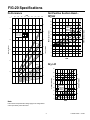
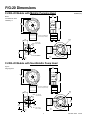
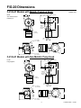
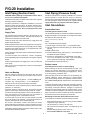
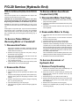
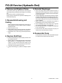
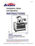
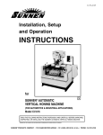
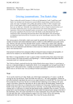
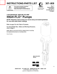
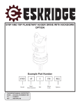
INSTALLATION & SERVICE
S
P
M
U
P
L
A
I
R
T
S
U
D
IN
Models: F-20, F-21, F-22
G-20, G-21, G-22
WANNER ENGINEERING, INC.
1204 Chestnut Avenue, Minneapolis, MN 55403
TEL: (612) 332-5681 FAX: (612) 332-6937
TOLL-FREE FAX [US only]: (800) 332-6812
www.hydra-cell.com
email: [email protected]
F/G-20 Contents
Page
Specifications ......................................................................... 2
Dimensions ............................................................................ 4
Installation .............................................................................. 7
Maintenance ........................................................................ 11
Service (Fluid End) .............................................................. 12
Service (Hydraulic End) ....................................................... 15
Troubleshooting ................................................................... 18
F/G-20 Specifications
Max Pressure
Metallic:
Non-Metallic:
Calculating Required
Horsepower (kW)*
F/G-20: 1000 psi (70 bar);
F/G-21/22: 1500 psi (100 bar)
All Models: 250 psi (17 bar)
Capacity @ Max Pressure
rpm
F/G-20-X
1750
F/G-20-E
1750
F/G-20-S
1750
F/G-20-B
1750
F/G-20-G
1750
2 x rpm
gpm
0.96
0.73
0.55
0.33
0.20
I/min
3.63
2.76
2.08
1.25
0.76
63,000
2 x rpm
84,428
Delivery @ Max Pressure
revs/gal revs/liter
F/G-20-X
1823
500
F/G-20-E
2397
659
F/G-20-S
3182
906
F/G-20-B
5303
1400
F/G-20-G
8750
2302
Max Inlet Pressure
+
+
gpm x psi
=
electric motor HP*
=
electric motor kW*
1,460
lpm x bar
511
* rpm equals pump shaft rpm. HP/kW is required application
power. Use caution when sizing motors with variable speed
drives.
100 psi (7 bar)
Max Temperature
Metallic Heads:
250°F (121°C) – consult factory for
temperatures above 160°F (71°C)
Non-Metallic Heads: 140°F (60°C)
Inlet Port
F-20: 1/2 inch NPT
G-20: 1/2 inch BSPT
Discharge Port
F-20: 3/8 inch NPT
G-20: 3/8 inch BSPT
Shaft Diameter
F-20: 5/8 inch hollow shaft for NEMA 56C
C-Face motor (with feet)
F-21/22: 5/8 inch
G-20: 19 mm for IEC 80 B5 Flange
motor (with feet)
G-21/22: 19 mm
Shaft Rotation
Bi-directional
Bearings
Radial ball
Oil Capacity
1/8 US quart (0.12 liters)
Weight
Metallic Head: 12 lbs (5.5 kg)
Non-Metallic Head: 9 lbs (4.1 kg)
Note:
Performance and specification ratings apply to all configurations
unless specifically noted otherwise.
2
F20-991-2400
5/1/04
F/G-20 Specifications
Performance
Net Positive Suction Head –
NPSHr
RPM
400
600
800
1000
1200
1400
1600
1800
22
20
6
18
F/G-20-X
F/G-20-E
F/G-20-S
F/G-20-B
F/G-20-G
1750
4.0
16
F/G-20-X
100 PSI (7 bar)
500 PSI (35 bar)
1000 PSI (70 bar)
1500 PSI (100 bar)
NPSHr (feet of water)
1.0
3.5
3.0
0.8
5
14
4
12
10
3
8
2.5
0.6
F/G-20-S
2.0
2
6
Liters per Minute
Gallons per Minute
F/G-20-E
NPSHr (meters of water)
200
1750
0
1.2
4
1
2
0
0
200
400
600
800
1000 1200 1400 1600 1800
RPM
1.5
0.4
Dry Lift
F/G-20-B
1.0
1750
4.0
0.2
3.5
Lift (feet of water)
3.0
F/G-20-G
0
100
F/G-20-X
80
2.5
2.0
60
F/G-20-E
F/G-20-S
F/G-20-B
F/G-20-G
1.5
40
Lift (cm of water)
0.5
1.0
20
0.5
0
0
200 400 600 800 1000 1200 1400 1600 1800
RPM
Note:
Performance and specification ratings apply to all configurations
unless specifically noted otherwise.
3
F20-991-2400
5/1/04
F/G-20 Dimensions
F-20/G-20 Models with Metallic Pumping Head
Inches (mm)
3.64
(92.5)
Brass
316 Stainless Steel
Hastelloy® C
Ø6.50
(165)
Ø5.870
(149)
8.38
(213)
F-20: 5/8" ID (for NEMA 56C)
G-20: 19 mm ID (for IEC 80)
2.20
(55.9)
Ø0.42
(10.7)
2.93
(74.4)
Outlet F-20: 3/8" NPT
G-20: 3/8" BSPT
0.72
(18.3)
4.15
(105)
0.65
(16.5)
3.25
(82.6)
Inlet F-20: 1/2" NPT
G-20: 1/2" BSPT
9.72
(247)
0.25
(6.4)
F-20/G-20 Models with Non-Metallic Pump Head
Kynar®
3.64
(92.5)
Polypropylene
Ø6.50
(165)
Ø5.870
(149)
8.63
(219.2)
F-20: 5/8" ID (for NEMA 56C)
G-20: 19 mm ID (for IEC 80)
2.20
(55.9)
2.93
(74.4)
Ø0.42
(10.7)
Outlet F-20: 3/8" NPT
G-20: 3/8" BSPT
0.72
(18.3)
4.15
(105)
0.65
(16.5)
3.25
(82.6)
Inlet F-20: 1/2" NPT
G-20: 1/2" BSPT
9.97
(253.2)
0.25
(6.4)
4
F20-991-2400
5/1/04
F/G-20 Dimensions
F-21/G-21 Models with Metallic Pumping Head
Brass
2.25
(57.2)
Inches (mm)
Ø0.33 (thru hole)
(8.4)
3.45
(87.6)
316 Stainless Steel
Hastelloy® C
2.12
(53.8)
5.18
(132)
8.93
(227)
Ø0.50
(12.7)
(thru hole
2 places)
F-21: Ø5/8"
G-21: Ø19 mm
0.96
(24.4)
Outlet F-21: 3/8 NPT
G-21: 3/8 BSPT
1.91
(48.5)
0.72
(18.3)
4.50
(114)
2.93
(74.4)
0.65
(16.5)
4.98
(127)
Inlet F-21: 1/2" NPT
G-21: 1/2" BSPT
F-21/G-21 Models with Non-Metallic Pump Head
Kynar®
2.25
(57.2)
Ø0.33 (thru hole)
(8.4)
3.45
(87.6)
Polypropylene
2.12
(53.8)
5.18
(132)
9.18
(233.2)
Ø0.50
(12.7)
(thru hole
2 places)
F-21: Ø5/8"
G-21: Ø19 mm
0.96
(24.4)
Outlet F-21: 3/8" NPT
G-21: 3/8" BSPT
1.91
(48.5)
0.72
(18.3)
4.50
(114)
2.93
(74.4)
0.65
(16.5)
4.98
(127)
Inlet F-21: 1/2" NPT
G-21: 1/2" BSPT
5
F20-991-2400
5/1/04
F/G-20 Dimensions
F-22/G-22 Models with Metallic Pumping Head
Inches (mm)
Brass
316 Stainless Steel
Hastelloy® C
Ø6.50
(165)
Ø5.870
(149)
8.38
(213)
Ø0.42
(10.7)
(4 x)
F-22: Ø5/8"
G-22: Ø19 mm
5.63
(143)
2.93
(74.4)
Outlet F-22: 3/8" NPT
G-22: 3/8" BSPT
0.72
(18.3)
4.15
(105)
0.65
(16.5)
Inlet F-22: 1/2" NPT
G-22: 1/2" BSPT
9.72
(247)
7.09
(180)
F-22/G-22 Models with Non-Metallic Pump Head
Kynar®
Polypropylene
Ø6.50
(165)
Ø5.870
(149)
8.63
(219.2)
Ø0.42
(10.7)
(4 x)
F-22: Ø5/8"
G-22: Ø19 mm
5.63
(143)
2.93
(74.4)
Outlet F-22: 3/8" NPT
G-22: 3/8" BSPT
0.72
(18.3)
4.15
(105)
0.65
(16.5)
Inlet F-22: 1/2" NPT
G-22: 1/2" BSPT
7.09
(180)
6
9.97
(253.2)
F20-991-2400
5/1/04
F/G-20 Installation
Location
Important Precautions
NOTE: The numbers in parentheses are the Reference
Numbers on the illustrations found later in this manual and
in the Parts Manual.
Adequate Fluid Supply. To avoid cavitation and
premature pump failure, be sure that the pump will have
an adequate fluid supply and that the inlet line will not be
obstructed. See “Inlet Piping”.
Locate the pump as close to the supply source as possible.
Install it in a lighted clean space where it will be easy to inspect
and maintain. Allow room for checking the oil level, changing
the oil, and removing the manifold (3) and valve plate (21).
Positive Displacement. This is a positive-displacement
pump. To avoid severe system damage if the discharge
line ever becomes blocked, install a relief valve
downstream from the pump. See “Discharge Piping”.
Mounting
Safety Guards. Install adequate safety guards over all
pulleys, belts, and couplings. Follow all codes and
regulations regarding installation and operation of the
pumping system.
The pump shaft can be rotated in either direction. To prevent
vibration, securely attach the pump or motor to a rigid base.
Shut-Off Valves. Never install shut-off valves between
the pump and discharge pressure regulator, or in the
regulator bypass line.
On a belt-drive system, align the sheaves accurately: poor
alignment wastes horsepower and shortens the belt and bearing
life. Make sure the belts are properly tightened, as specified by
the belt manufacturer.
Freezing Conditions. Protect the pump from freezing.
See also the Maintenance Section.
On a direct-drive system, align the shafts accurately.
Consult the Factory for the following situations:
On a close-coupled system, coat the motor shaft liberally with
Loctite® Nickel Anti-Seize #77164.
•
•
•
•
•
•
7
Extreme temperature applications (above 160° F or
below 40° F)
Pressure feeding of pumps
Viscous or abrasive fluid applications
Chemical compatibility problems
Hot ambient temperatures (above 110° F)
Conditions where pump oil may exceed 200° F
because of a combination of hot ambient temperatures,
hot fluid temperature, and full horsepower load — an
oil cooler may be required
F20-991-2400
5/1/04
F/G-20 Installation
Inlet Piping (Suction Feed)
Inlet Piping (Pressure Feed)
CAUTION: When pumping at temperatures above 160° F
(71°C), use a pressure-feed system.
Provide for permanent or temporary installation of a vacuum/
pressure gauge to monitor the inlet vacuum or pressure.
Pressure at the pump inlet should not exceed 250 psi (173 bar);
if it could get higher, install an inlet pressure regulator. Do not
supply more than one pump from the same inlet line.
Install draincocks at any low points of the suction line, to permit
draining in freezing conditions.
Provide for permanent or temporary installation of a vacuum
gauge to monitor the inlet suction. To maintain maximum flow,
vacuum at the pump inlet should not exceed 7 in. Hg (180 mm
Hg). Do not supply more than one pump from the same
inlet line.
Inlet Calculations
Acceleration Head
Calculating the Acceleration Head
Supply Tank
Use the following formula to calculate acceleration head losses.
Subtract this figure from the NPSHa, and compare the result to
the NPSHr of the Hydra-Cell pump.
Use a supply tank that is large enough to provide time for any
trapped air in the fluid to escape. The tank size should be at
least twice the maximum pump flow rate.
Ha = (L x V x N x C) ÷ (K x G)
Isolate the pump and motor stand from the supply tank, and
support them separately.
where:
Ha = Acceleration head (ft of liquid)
L= Actual length of suction line (ft) — not equivalent length
V= Velocity of liquid in suction line (ft/sec) [V = GPM x (0.408 ÷
pipe ID2)]
N= RPM of crank shaft
C= Constant determined by type of pump — use 0.628 for the
F/G-20/21/22 Hydra-Cell pump
K= Constant to compensate for compressibility of the fluid —
use: 1.4 for de-aerated or hot water; 1.5 for most liquids;
2.5 for hydrocarbons with high compressibility
G= Gravitational constant (32.2 ft/sec2)
Install a separate inlet line from the supply tank to each pump.
Install the inlet and bypass lines so they empty into the supply
tank below the lowest water level, on the opposite side of the
baffle from the pump suction line.
If a line strainer is used in the system, install it in the inlet line to
the supply tank.
To reduce aeration and turbulence, install a completely
submerged baffle plate to separate the incoming and outgoing
liquids.
Install a vortex breaker in the supply tank, over the outlet port
to the pump.
Friction Losses
Place a cover over the supply tank, to prevent foreign objects
from falling into it.
Calculating Friction Losses in Suction Piping
When following the above recommendations (under “inlet
Piping”) for minimum hose/pipe I.D. and maximum length,
frictional losses in the suction piping are negligible (i.e., Hf = 0)
if you are pumping a water-like fluid.
Hose and Routing
Size the suction line at least one size larger than the pump
inlet, and so that the velocity will not exceed 1-3 ft/sec (0.3 to
0.9 m/s):
For pipe in inches: Velocity (ft/sec) = 0.408 x GPM/Pipe ID 2
When pumping more-viscous fluids such as lubricating oils,
sealants, adhesives, syrups, varnishes, etc., frictional losses
in the suction piping may become significant. As Hf increases,
the available NPSH (NPSHa) will decrease, and cavitation will
occur.
For pipe in mm: Velocity (m/sec) = 21.2 x LPM/Pipe ID2
Keep the suction line as short and direct as possible.
In general, frictional losses increase with increasing viscosity,
increasing suction-line length, increasing pump flowrate, and
decreasing suction-line diameter. Changes in suction-line
diameter have the greatest impact on frictional losses: a 25%
increase in suction-line diameter cuts losses by more than two
times, and a 50% increase cuts losses by a factor of five times.
Use flexible hose and/or expansion joints to absorb vibration,
expansion, or contraction.
If possible, keep the suction line level. Do not have any high
points to collect vapor unless these high points are vented.
To reduce turbulence and resistance, do not use 90° elbows. If
turns are necessary in the suction line, use 45° elbows or
arrange sweeping curves in the flexible inlet hose.
If a block valve is used, be sure it is fully opened so that the
flow to the pump is not restricted. The opening should be at
least the same diameter as the inlet plumbing ID.
Do not use a line strainer or filter in the suction line unless
regular maintenance is assured. If used, it should have a freeflow area of at least three times the free-flow area of the inlet.
Consult the factory before pumping viscous fluids.
Minimizing Acceleration Head and Frictional Losses
To minimize the acceleration head and frictional losses:
•
•
•
Install piping supports where necessary to relieve strain on the
inlet line and to minimize vibration.
•
•
8
Keep inlet lines less than 1 ft (0.3 m) long (suction stabilizer
required for longer inlet lines)
Use at least 5/8 in. (16 mm) I.D. inlet hose
Use soft hose (low-pressure hose, noncollapsing) for the
inlet lines
Minimize fittings (elbows, valves, tees, etc.)
Use a suction stabilizer on the inlet.
F20-991-2400
5/1/04
F/G-20 Installation
Minimizing Acceleration Head and Frictional
Losses
Discharge Piping
To minimize the acceleration head:
Note: Consult the Factory before manifolding two or more
pumps together.
•
•
•
Hose and Routing
•
•
Keep inlet lines less than 3 ft (1 m) long
Use at least 5/8” (16mm) I.D. inlet hose
Use soft hose (low-pressure hose, noncollapsing) for the
inlet lines
Minimize fittings (elbows, valves, tees, etc.)
Use a suction stabilizer on the inlet.
Use the shortest, most-direct route for the discharge line.
Select pipe or hose with a working pressure rating of at least
1.5 times the maximum system pressure. EXAMPLE: Select a
1500 psi (103 bar) W.P.-rated hose for systems to be operated
at 1000 psi (69 bar) gauge pressure.
Net Positive Suction Head
Use about 6 ft (1.8 m) of flexible hose between the pump and
rigid piping to absorb vibration, expansion or contraction.
NPSHa must be equal to or greater than NPSHr. If not, the
pressure in the pump inlet will be lower than the vapor pressure
of the fluid— and cavitation will occur.
Calculating the NPSHa
Support the pump and piping independently. Size the discharge
line so that the velocity of the fluid will not exceed 7-10 ft/sec
(2-3 m/sec):
Use the following formula to calculate the NPSHa:
For pipe in inches: Velocity (ft/sec) = 0.408 x GPM/Pipe ID2
NPSHa = Pt + Hz - Hf - Ha - Pvp
For pipe in mm: Velocity (m/sec) = 21.2 x LPM/Pipe ID2
where:
Pressure Regulation
Pt = Atmospheric pressure
Install a pressure regulator or unloader in the discharge line.
Bypass pressure must not exceed the pressure limit of the pump.
Hz = Vertical distance from surface liquid to pump centerline (if
liquid is below pump centerline, the Hz is negative)
Size the regulator so that, when fully open, it will be large enough
to relieve the full capacity of the pump without overpressurizing
the system.
Hf = Friction losses in suction piping
Ha = Acceleration head at pump suction
Pvp = Absolute vapor pressure of liquid at pumping temperature
NOTES:
Locate the valve as close to the pump as possible and ahead
of any other valves.
• In good practice, NPSHa should be 2 ft greater than NPSHr
• All values must be expressed in feet of liquid
Atmospheric Pressure at Various Altitudes
Adjust the pressure regulating valve to no more than 10% over
the maximum working pressure of the system. Do not exceed
the manufacturer’s pressure rating for the pump or regulator.
Altitude Pressure
(ft)
(ft of H 2O)
0
33.9
500
33.3
1000
32.8
Route the bypass line to the supply tank, or to the suction line as
far as possible from the pump (to reduce the chance of turbulence).
Altitude Pressure
(ft)
(ft of H 2O)
1500
32.1
2000
31.5
5000
28.2
If the pump will be operating for a long time with the discharge
closed and fluid bypassing, install a thermal protector set to
trip at 140° F in the bypass line (to prevent severe temperature
buildup in the bypassed fluid).
CAUTION: Never install shutoff valves in the bypass line
or between the pump and pressure regulator or relief valve.
Provide for permanent or temporary installation of a pressure
gauge to monitor the discharge pressure at the pump.
For additional system protection, install a safety relief valve in
the discharge line, downstream from the pressure regulator.
9
F20-991-2400
5/1/04
F/G-20 Installation
Before Initial Start-Up
Initial Start-Up Procedure
Before you start the pump, be sure that:
1. Turn on power to the pump motor.
2. Check the inlet pressure or vacuum. To maintain maximum
flow, inlet vacuum must not exceed 7 in. Hg. Inlet pressure
must not exceed 250 psi (17.3 bar).
3. Listen for any erratic noise and look for unsteady flow.
4. If the system has an air lock and the pump fails to prime:
a.
Turn off the power.
b.
Remove the pressure gauge or plug from the tee fitting
at the pump outlet (refer to the illustration on page 3).
NOTE: Fluid may come out of this port when the plug
is removed. Provide an adequate catch basin for fluid
spillage, if required. Fluid will come out of this port when
the pump is started, so we recommend that you attach
adequate plumbing from this port so fluid will not be
sprayed or lost. Use high-pressure-rated hose and
fittings from this port. Take all safety precautions to
assure safe handling of the fluid being pumped.
c.
Jog the system on and off until the fluid coming from
this port is air-free.
d.
Turn off the power.
e.
Remove the plumbing that was temporarily installed,
and reinstall the pressure gauge or plug.
5. Adjust the discharge pressure regulator to the desired
operating and bypass pressures. Do not exceed the
maximum pressure rating of the pump.
6. After the pressure regulator is adjusted, set the “pop-off”
safety relief valve at 100 psi higher than the desired
operating pressure.
7. Pumps fitted with Teflon diaphragms require 2 psi (0.14 bar)
minimum inlet pressure.
•
•
•
•
•
•
All shut-off valves are open, and the pump has an adequate
supply of fluid.
All connections are tight.
The oil reservoir beneath the reservoir diaphragm (71) is
completely full. NOTE: The reservoir is filled and sealed at
the factory. If you are unsure about the oil level, remove the
cover (70) and slowly lift the diaphragm (71). Refer to Service
Procedure #6, “Fill and Seal the Oil Reservoir”, in the FluidEnd Service Section.
The relief valve on the outlet of the pump is adjusted so the
pump starts under minimum pressure.
All pulleys and belts are properly aligned, and belts are
tensioned according to specification.
All pulleys and belts have adequate safety guards.
10
F20-991-2400
5/1/04
F/G-20 Maintenance
NOTE: The numbers in parentheses are the Ref. Nos. on
the illustrations in the Parts Manual.
Shutdown Procedure During
Freezing Temperatures
Periodically
Take all safety precautions to assure safe handling of the
fluid being pumped. Provide adequate catch basins for fluid
drainage and use appropriate plumbing from drain ports,
etc., when flushing the pump and system with a compatible
antifreeze.
Change the oil after the first 100 hours of operation, then change
according to the guidelines below. When changing, remove the
drain plug (69), Allow all oil and contaminant to drain out.
1. Adjust the discharge pressure regulating valve so the pump
runs under minimum pressure. Stop the pump.
2. Drain supply tank; open any draincocks in system piping
and collect drainage. Drain as much fluid from the pump
manifold and plumbing attached directly to the pump
manifold by loosening fittings or removing plugs or gauges.
3. Close draincocks in system piping and tighten or replace
any fittings, gauges or plugs.
4. Fill supply tank with enough antifreeze to fill system piping
and pump.
NOTE: Disconnect the system return line from the
supply tank and connect it to a separate reservoir.
5. Start the pump and allow it to run until the system is filled
with antifreeze. NOTE: If the system has an airlock and
the pump fails to prime, follow step 4 of the Initial Startup Procedure to clear the air.
6. When mostly antifreeze is flowing from the system return
line, stop the pump. Connect the system return line back to
the supply tank and circulate the antifreeze for a short period.
7. It is also good practice to change the oil in the hydraulic end
before storage for an extended period. This will remove any
accumulated condensation and sediment from the oil
reservoir. Drain and refill the hydraulic end with the
appropriate Hydra-Oil and operate the pump for a short
period to assure smooth performance.
Hours Between Oil Changes @ Various
Process Fluid Temperatures
RPM
<90°F
(32°C)
<139°F
(60°C)
<180°F
(82°C)
Metallic Pump Head
<1000 psi (70 bar) <1200
<1800
6,000
3,000
4,000
2,000
2,000
1,500
<1500 psi (100 bar) <1200
<1800
3,000
1,500
2,000
1,000
1,500
1,000
Non-Metallic Pump Head
<250 psi (17 bar)
<1200
<1800
3,000
1,500
2,000
1,000
—
—
Pressure
NOTE: Minimum oil viscosity for proper hydraulic end
lubrication is 16-20 cST (80-100 SSU).
CAUTION: Do not turn the drive shaft while the oil reservoir is
empty.
There should be no trapped air under the oil reservoir diaphragm
(71). Refer to Service Procedure #6, “Fill and Seal the Oil
Reservoir”, in the Fluid-End Service Section.
Use the appropriate Hydra-Oil for the application (contact
Wanner Engineering if in doubt).
CAUTION: If you are losing oil but don’t see any external
leakage, or if the oil becomes discolored and contaminated,
the diaphragm (22) may be damaged. Refer to the FluidEnd Service Section. Do not operate the pump with a
damaged diaphragm.
CAUTION: Do not leave contaminated oil in the pump
housing or leave the housing empty. Remove contaminated
oil as soon as discovered, and replace it with clean oil.
Check the inlet pressure or vacuum periodically with a gauge.
CAUTION: Protect the pump from freezing. Refer also to the
“Shutdown Procedure”.
11
F20-991-2400
5/1/04
F/G-20 Service (Fluid End)
See Hydraulic End for
pump housings
Bolt Torque Specifications
Ref. No.
1
20
22
23
F-20/21/22
(in-lbs)
90
14
10
14
G-20/21/22
(Ncm)
1,017
158
113
158
12
F20-991-2400
5/1/04
F/G-20 Service (Fluid End)
NOTE: The number in parentheses are the Reference
numbers on the illustration at right (also shown in the Parts
Manual).
3. Inspect and Replace
Diaphragm (22)
This section explains how to disassemble and inspect all easilyserviceable parts of the pump. Repair procedures for the
hydraulic end (oil reservoir) of the pump are included in a later
section of the manual.
a. Use a 3-mm Allen wrench to remove the two capscrews
(20) from the valve plate (21).
b. Lift the diaphragm by one edge, and turn the pump shaft
until the diaphragm moves up to “top dead center”. This
will expose machined cross holes in the plunger shaft
behind the diaphragm.
NOTE: If the pump has a hollow shaft, use the shaft
rotator from the Wanner Tool Kit.
c. Insert the plunger holder (from the Wanner Tool Kit)
through one of the machined cross holes, to hold the
diaphragm up. The proper size tool is included in the
Wanner Tool Kit. (Don’t remove the tool until the new
diaphragm is installed in step “G” below).
d. Unscrew the diaphragm. Use an 8-mm or 5/16-in. openend wrench, and turn counterclockwise.
e. Inspect the diaphragm carefully. A damaged diaphragm
generally indicates a pumping system problem, and
replacing only the diaphragm will not solve the larger
problem. Inspect the diaphragm for the following:
• Small puncture. Usually caused by a sharp foreign
object in the fluid, or by an ice particle.
• Diaphragm pulled away from the sides. Usually
caused by fluid being frozen in the pump, or by
overpressurization of the pump.
• Diaphragm becoming stiff and losing flexibility.
Usually caused by pumping a fluid that is incompatible
with the diaphragm material.
• Diaphragm edge chewed away. Usually caused by
overpressurizing the system.
CAUTION: If a diaphragm has ruptured and foreign
material or water has entered the oil reservoir, do
not operate the pump. Check the diaphragm, then
flush the reservoir completely (as outlined below)
and refill it with fresh oil. Never let the pump stand
with foreign material or water in the reservoir, or with
the reservoir empty.
f. Clean away any spilled oil. Apply Loctite #242
Threadlocker to the threads of the new diaphragm (or
the old one, as appropriate).
g. Install the diaphragm and tighten to 10 in-lbs.
NOTE: All bolts, nuts, and screws are metric sizes.
CAUTION: Do not disassemble the hydraulic end unless
you are a skilled mechanic. For assistance, contact Wanner
Engineering (612-332-5681) or the distributor in your area.
1. Remove Manifold (3)
a. Remove all eight bolts (1) around the manifold.
b. Remove the manifold (3).
c. Inspect the manifold for warping or wear around the inlet
and outlet ports. If wear is excessive, replace the manifold
or return it to Wanner Engineering for resurfacing.
To check if the manifold is warped, place a straightedge
across it. A warped manifold should be replaced.
2. Inspect Valves (4-17)
The inlet and outlet valve assemblies are different (the
inlet valve is larger) and face in opposite directions.
Inspect each valve as follows:
a. Check the spring retainers (4,17), and replace if worn.
b. Check the valve springs (5,16). If shorter than a new
spring, replace them (do not just stretch the old spring).
c. Check the valve poppets (6,15). If worn excessively,
replace them.
d. Remove the valve seats (9,13). A seat puller is included
in the Wanner Tool Kit.
Inspect the valve seats for wear, and replace if necessary.
A new O’ring (8,12) should be installed.
e. Check the dampening washers (10,11), and replace if
worn.
f. Reinstall the valve assemblies:
• Clean the valve ports and shoulders with emery cloth,
and lubricate them with lubricating gel or petroleum jelly
(do not use petroleum products when installing EPDM
O-rings).
• Install the O-rings (8,12) on the valve seats (9,13).
• Inlet Valve. Insert the spring retainer (17) into the valve
plate, then insert the spring, valve, Tetra seal, valve seat,
and dampening washer (16 - 11). A flat O-ring [Tetra seal]
(14) goes between the retainer and seat.
• Outlet Valve. Insert the dampening washer, valve seat,
Tetra seal, valve, and spring, then the retainer. Install
the flat O-ring between the retainer and seat.
13
F20-991-2400
5/1/04
F/G-20 Service (Fluid End)
4. Flush Contaminant from
Hydraulic End (only if a
diaphragm has ruptured)
6. Fill and Seal the Oil Reservoir
a. The oil reservoir diaphragm (71) protrudes down into the
pump housing approximately 1/4 to 3/8 in. Add oil, if
required, so that when the diaphragm is set into the
reservoir all air is pushed out.
Take care not to allow any oil overflow to get between
the pump housing (62 or 66) and the cover (54). This
may result in an apparent oil leak later, when the pump
is put into use and heats up.
b. Install the cover (70) using the four bolts.
c. Wipe off any excess oil that got squeezed out onto the
outside of the pump housing.
NOTE: The diaphragm (71) will flex up and down slightly
as the pump operates. The vent holes in the reservoir
cover (70) allow this action to freely occur.
a. With the valve plate and manifold still removed (see
above), remove the oil drain cap (69), and the oil reservoir
cover (70) and diaphragm (71). Allow all oil and
contaminant to drain out.
b. Fill the reservoir with kerosene or solvent, manually turn
the pump shaft to circulate the kerosene, and drain.
Dispose of this contaminated fluid properly.
CAUTION: If you have an EPDM diaphragm, or if food
grade oil is in the reservoir, do not use kerosene or
solvents. Instead, flush with the same lubricant that
is in the reservoir. Pumps with an EPDM diaphragm
have an “E” as the 7th digit of the Model No.
c. Repeat the flushing procedure (step “b” above).
d. Fill the reservoir with fresh oil, manually turn the pump
shaft to circulate the oil, and drain once again.
e. Refill the reservoir. If the oil appears milky, there is still
contaminant in the reservoir. Repeat the flushing
procedure until the oil appears clean.
7. Reinstall Valve Plate (21) and
Manifold (3)
a. Reinstall the valve plate (21), with the valve assemblies
installed as outlined above, onto the diaphragm plate
(24).
b. Reinstall the O-rings (18,19) onto the valve plate (21).
Use petroleum jelly or lubricating gel to hold them in place
(do not use petroleum products when installing EPDM
O-rings).
c. Reinstall the manifold onto the valve plate.
d. Insert all bolts (1) around the edge of the manifold, and
alternately tighten opposite bolts until all are secure.
Torque to 90 in.-lbs.
e. Recheck all bolts for tightness.
5. Prime the Hydraulic Cell
a. With the pump horizontal, fill the reservoir with the
appropriate Hydra oil for the application.
b. All air in the oil within the hydraulic cell (behind the
diaphragm) must be forced out by turning the shaft —
and thus pumping the piston. A shaft rotator is included
in the Wanner Tool Kit.
Turn the shaft until a bubble-free flow of oil comes from
behind the diaphragm. Watch the oil level in the reservoir;
if it gets too low during priming, air will be drawn into the
piston (inside the hydraulic end). This will cause the pump
to have a loss in flow, and you will have to start over
again with priming the hydraulic cell. Fill oil reservoir
completely. Add diaphragm seal and install cover plate.
c. Wipe excess oil from the cover plate and diaphragm.
14
F20-991-2400
5/1/04
F/G-20 Service (Hydraulic End)
F/G-21Pump Housing
F/G-20 and F/G-22
Pump Housing
F/G-21 and F/G-22
Shaft and Keyway
F/G-20 Only
F/G-20
Hollow
Shaft
See Fluid End for
Piston Assembly
Bolt Torque Specifications
Ref. No.
50
52
72
75
F-20/21/22
(in-lbs)
35
14
10
35
G-20/21/22
(Ncm)
396
158
113
396
15
F20-991-2400
5/1/04
F/G-20 Service (Hydraulic End)
NOTE: The numbers in parentheses are the Reference
numbers on the illustration at right (also shown in the Parts
Manual).
To Remove Motor from DirectCoupled Unit (F20)
This section explains how to disassemble and inspect the
hydraulic end (oil reservoir) of the pump.
1. Disassemble Motor from Pump
CAUTION: Do not disassemble the hydraulic end unless
you are a skilled mechanic. For assistance, contact Wanner
Engineering (612-332-5681) or the distributor in your area.
a. Remove the four bolts and flat washers that secure the
pump and motor together.
b. Install two of the bolts into the threaded holes in the pump
flange (51).
c. Alternately turn the bolts clockwise until the pump and
motor separate.
Depending on the repair you are attempting, you may or may
not have to remove the motor from a direct-drive pump/motor
unit.
Internal piston components (26 - 32) can be serviced without
removing the motor or crankshaft. The motor and crankshaft
must be removed to service the connecting rod (59), piston
(33), crankshaft (58), front bearing (60), back bearing (57), or
seal (56).
2. Reassemble Motor to Pump
a. Thoroughly clean the motor shaft and the hollow pump
shaft.
b. Apply a liberal amount of Loctite Nickel Anti-Seize
#77164 to the pump shaft.
c. Install the shaft key into the motor shaft keyway.
d. Slide the motor shaft into the hollow pump shaft.
CAUTION: When assembling this pump to the directcoupled motor, be careful that the shaft key remains in
the motor shaft keyway and does not ride up the keyway
and contact the shaft seal (which would cause premature
seal failure). Incorrect key placement could also cause
the hollow pump shaft to fail.
Use a screwdriver to move the shaft key back in the motor
shaft keyway as the motor and pump are drawn together.
e. Reinstall the four bolts and flat washers.
To Service Piston Without
Removing Motor or Crankshaft
1. Disassemble Piston
a.
b.
c.
d.
Remove the manifold, valve plate, diaphragm plate and
diaphragm, and drain the oil from the pump (see the
Fluid-End Service Section):
Remove the snap ring (26) from the piston, using a
standard #1 snap-ring pliers.
Pull out the valve plunger (29). This also removes the
washer (27) and spring (28).
(31), and pull the cylinder out of the piston. Be careful
not to damage the piston.
Inspect all parts, and replace the O-ring and any other
parts that are worn or may be damaged.
To Service Remainder of
Hydraulic End
1. Remove Pump Housing
2. Reassemble Piston
a. Remove the manifold, valve plate, and diaphragm, as
outlined in the Fluid-End Service Section.
b. Drain the oil from the pump housing by removing the
drain plug (69), and the oil reservoir cover (70) and
diaphragm (71).
c. Stand the pump on end, with the drive shaft up.
d. Remove the bolts (52) that secure the cover (54) to the
housing (62 or 66). Use a 5-mm socket wrench. Save
the O-rings (53).
e. Remove the cover and the cover O-ring (55).
f. Remove the crankshaft (58) by pulling it through the
connecting rod (59).
a. Tip the pump so the piston is upright.
b. Drop the ball (32) into the opening in the bottom of the
piston.
c. Insert the valve plunger (29) into the valve cylinder (31).
Slide the spring (28) over the plunger, inside the valve
cylinder.
d. Slide the assembled valve cylinder, plunger, and spring
(28 - 31) into the piston (33).
e. Insert the washer (27) over the plunger.
f. Using the snap-ring pliers, insert the snap ring (26) into
the piston.
16
F20-991-2400
5/1/04
F/G-20 Service (Hydraulic End)
2. Remove and Replace Piston
5. Reinstall Diaphragm
To remove the piston (33), first remove the connecting rod
(59) and pin (61) by pressing the pin through the connecting
rod.
Reverse the process to reinstall the piston.
Refer to Steps 5 and 6 below to replace the diaphragm and
reassemble the pump.
a. Screw the plunger puller (from the Wanner Tool Kit or
Repair Kit) into the plunger (29). Pull out to expose the
cross hole in the plunger. Rotate the shaft until the piston
is at top dead center.
b. Insert the diaphragm wrench (from the Wanner Tool Kit),
or similar dowel-type object, through the plunger hole —
to hold the plunger away from the diaphragm plate (24),
and to keep the plunger from turning when the diaphragm
is being installed.
c. Apply a small amount of Loctite #242 to the threads of
the diaphragm (be sure the threads are clean).
d. Set the diaphragm (22) on the plunger (29), ridge-side
out. Screw the diaphragm onto the plunger.
e. Hold the diaphragm wrench, and tighten the diaphragm
to 10 in.-lbs of torque.
f. Fill the reservoir with fresh oil and prime the pump, as
outlined in the Fluid-End Service Section.
3. Reassemble Housing and
Casting
NOTE: Inspect the shaft seal (56) before continuing. If it
looks damaged in any way, replace it. Refer to “Replace
Shaft Seal” below.
a. Stand the pump on end.
b. With the piston and connecting rod in place, reinstall the
crankshaft by threading it through the connecting rod.
c. Reinstall the cover, cover O-ring, and bolts (with their Orings).
6. Reassemble Pump
Fill and seal the oil reservoir, then reassemble the pump
as outlined in the Fluid-End Service Section.
4. Replace Shaft Seal
a. Press the back bearing (57) and seal (56) out of the cover
(54). Discard the seal.
b. Apply a coating of Loctite High-Performance Pipe Sealant
With Teflon®, or a comparable product, to the outer
surface of a new seal and the inside surface of the
opening in the back cover (54) where the seal will rest.
c. Press the new seal into the back cover.
d. Inspect the bearing (57). If pitted or damaged, replace
it.
17
F20-991-2400
5/1/04
F/G-20 Troubleshooting
Cavitation
Pump Runs Rough
•
•
•
•
•
•
•
•
•
Inadequate fluid supply caused by:
– Inlet line collapsed or clogged
– Clogged line strainer
– Inlet line too small or too long
– Air leak in inlet line
– Worn or damaged inlet hose
– Suction line too long
– Too many valves and elbows in inlet line
– NPSHa is less than NPSHr
Fluid too hot for inlet suction piping system.
Air entrained in fluid piping system.
Aeration and turbulence in supply tank.
Inlet suction vacuum too high.
•
•
•
•
•
•
•
Premature Failure of Diaphragm
(22)
Symptoms of Cavitation
•
•
•
•
Worn pump valves
Airlock in outlet system
Oil level low
Wrong weight of oil for cold operating temperatures (change
to lighter weight)
Cavitation
Air in suction line
Restriction in inlet/suction line
Hydraulic cells not primed after changing diaphragm (22)
Foreign material in inlet or outlet valve
Damaged diaphragm (22)
Broken valve spring (5,16)
Excessive pump valve noise
Premature failure of spring or retainer (4,5,16,17)
Volume or pressure drop
Rough-running pump
•
•
•
•
•
Drop in Volume or Pressure
Frozen pump
Puncture by a foreign object
Elastomer incompatible with fluid being pumped
Pump running too fast
Excess pressure
A drop in volume or pressure can be caused by one or more of
the following:
Water in Oil Reservoir
•
•
•
•
•
•
•
•
•
•
•
•
•
•
•
•
•
•
•
•
•
•
•
•
•
Air leak in suction piping
Clogged suction line or suction strainer
Suction line inlet above fluid level in tank
Inadequate fluid supply
Pump not operating at proper RPM
Relief valve bypassing fluid
Worn pump valve parts
Foreign material in inlet or outlet valves
Loss of oil prime in cells because of low oil level
Ruptured diaphragm (22)
Cavitation
Warped manifold from overpressurized system
O-rings forced out of their grooves from overpressurization
Air leak in suction line strainer or gasket
Cracked suction hose.
Empty supply tank
Excessive aeration and turbulence in supply tank
Abrasives in the fluid
Valve incompatible with corrosives in the fluid
Pump running too fast
Worn and slipping drive belt(s)
Worn spray nozzle(s)
•
Condensation
Ruptured diaphragm (22)
Hydraulic cell not properly primed after diaphragm (22)
replacement
Frozen pump
Strong Water Pulsations
NOTE: Small pulsations are normal with a single-acting
pump.
•
•
•
•
•
•
18
Foreign object lodged in pump valve
Loss of prime in hydraulic cell because of low oil level
Air in suction line
Valve spring (5,16) broken
Cavitation
Aeration or turbulence in supply tank
F20-991-2400
5/1/04
F/G-20 Troubleshooting
Valve Wear
•
Normal wear
Pump Runs, But Fluid Doesn’t
Flow
•
Unit air-locked
Loss of Oil
•
•
•
•
•
•
External seepage
Rupture of diaphragm (22)
Frozen pump
Worn shaft seal
Oil drain, fill cap, or oil reservoir cover loose
Valve plate and manifold bolts loose
Premature Failure of Valve
Spring or Retainer
•
•
•
•
Cavitation
Foreign object in the pump
Pump running too fast
Spring/retainer material incompatible with fluid being
pumped
19
F20-991-2400
5/1/04
Limited Warranty
Wanner Engineering, Inc. extends to the original purchaser
of equipment manufacturerd by it and bearing its name, a
limited one-year warranty from the date of purchase against
defects in material or workmanship, provided that the
equipment is installed and operated in accordance with
the recommendations and instructions of Wanner
Engineering, Inc. Wanner Engineering, Inc. will repair or
replace, at its option, defective parts without charge if such
parts are returned with transportation charges prepaid to
Wanner Engineering, Inc., 1204 Chestnut Avenue,
Minneapolis, Minnesota 55403.
This warranty does not cover:
1. The electric motors (if any), which are covered by the
separate warranties of the manufacturers of these
components.
2. Normal wear and/or damage caused by or related to
abrasion, corrosion, abuse, negligence, accident, faulty
installation or tampering in a manner which impairs normal
operation.
3. Transportation costs.
This limited warranty is exclusive, and is in lieu of any other
warranties (express or implied) including warranty of
merchantability or warranty of fitness for a particular
purpose and of any noncontractual liabilities including
product liabilities based on negligence or strict liability.
Every form of liability for direct, special, incidental or
consequential damages or loss is expressly excluded and
denied.
WANNER ENGINEERING, INC.
1204 Chestnut Avenue, Minneapolis, MN 55403
TEL: (612) 332-5681 FAX: (612) 332-6937
TOLL-FREE FAX [US only]: (800) 332-6812
www.hydra-cell.com
email: [email protected]
©2004 Wanner Engineering, Inc. Printed in USA
20
F20-991-2400
5/1/04