1
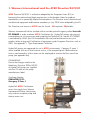
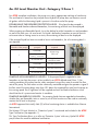
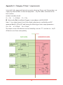
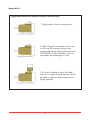
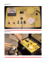
Wanner International
and
ATEX
Directive 94/9/EC
Covers - Category 2 Zone 1 and
Category 3 Zone 2 requirements
Date of issue 9/07
Contents:
Page
1.
Wanner International and the
ATEX Directive 94/9/EC
4
2.
Operating Conditions
5
3.
Drive Motors
5
4.
a. Oil Level Monitor Unit - Category 2 Zone 1
b. Oil Level sight Bowl - Category 3 Zone 2
6
5.
a) Markings of Conformity - Category 2 Zone 1
b) Markings of Conformity - Category 3 Zone 2
7
6.
Earthing / Grounding
8
7.
Pumpable Materials
9
8.
Maintenance
10
9.
General notes
10
- Appendix 1
Copy of Certificate
11
- Appendix 2
Max pressure values all models
13
- Appendix 3
Manufacturers' approach
14
- Appendix 4
- Appendix 5
Schematic of oil level monitoring unit
Circuit diagrams
(Oil level monitoring units)
15
16
- Appendix 6
Filling oil reservoir bowl
17
- Appendix 7
Portable Appliance Tester
18
- Appendix 8
Oil Level sight Bowl
19
2
1. Wanner International and the ATEX Directive 94/9/EC
ATEX Directive 94/9/EC is a directive adopted by the European Union (EU) to
harmonise the technical and legal requirements in the Member States for products
intended for use in potentially explosive atmospheres. The Directive covers electrical and
non-electrical equipment and became mandatory in July 2003 when adopted by the EU.
The Directives are known as ATEX from the French - ATmospheres EXplosibles.
Wanner International Ltd has worked with an outside specialist agency called Intertek
ETL SEMKO in order to obtain ATEX Certification for Hydra-Cell pumps carrying out
a comprehensive risk assessment and compiling the Technical File. Intertek ETL SEMKO
is accredited by UKAS (the UK Accreditation Service) and authorised to carry out
product safety testing and Certification of equipment under European Directives such as
ATEX. See appendix 1 “Type Examination Certificate.”
Hydra-Cell pumps are approved for use in ATEX environments - Category 2 zone 1when installed with an oil level monitor unit or, if the pumped liquid is deemed to be
inert or non-hazardous a flow meter can be employed to monitor the flow rate of the
pump (see appendix 4a).
CE MARKING
Due to the changes made to the
Machinery Directive 2006/42/EC
all Hydra-Cell pumps are supplied
with the CE mark on the pump
manufacturers label.
Certificate Number:
ITS04ATEX11919 Category 2 Zone 1
Hydra-Cell ATEX Certification
covers the supply from Wanner
International of bare shaft pumps
only and not complete pump and
electric motor sets.
3
2. Operating Conditions
The normal operating environment is an indoor or outdoor above ground industrial
environment in which flammable dust could be present.
The intended external ambient operating temperature range is (minus) -10ºC to 40ºC.
The intended internal operating temperature range is (minus) -10ºC to 90ºC.
This is the maximum temperature range for Hydra-Cell pumps with ATEX. Certain
diaphragm materials have operating limits within this temperature range. Contact Wanner
International for more information and assistance.
Wanner International has obtained Type Certification, for conditions outside the pump as
follows:CE Ex II 2G & D outside T4 amb (max process temperature 90°C)
Group II (Zone 1), Category 2 G (gasses) & D (dust)
T4 135°C (auto ignition temperature)
By designing equipment suitable for use in Category 2 Zone 1 areas, operation in
Category 3 Zone 2 area is also permitted.
Category 3 Zone 2 only - Where the end-user will take responsibility to ensure oil is always
present in the pump hydraulic-end, then a simple 'oil level sight bowl' can be fitted (see
appendix 8). The user must never start or continue running the pump when oil is not visible.
The pump is not intended to pump dusts but is intended for use in dust hazardous atmospheres.
3. Drive Motors
Hydra-Cell ATEX Certification covers the supply from Wanner International of bare shaft
pumps only and not complete pump and electric motor sets.
The supplier of the drive motor and motor control system must provide over current and
short circuit protection that is capable of shutting down the pump before the motor
produces more than 85% of the input power limit of the hydraulic-end.
The input power limit can be calculated using the Hydra-Cell standard power
requirements formula (see product specification sheets on website) at maximum speed
and pressure for any given pump (see appendix 2).
This is necessary to ensure that the bearings are operating with a 25% safety margin,
satisfying the explosion safety design concept described in clause 1.0.1 in the Technical
File (see appendix 3).
4
4a. Oil Level Monitor Unit - Category 2 Zone 1
For ATEX compliant installations, the pumps must carry appropriate markings of conformity.
The certification is based on the principle that a Hydra-Cell pump does not create a source
of ignition while the lubricating liquid is present in the drive end of the pump.
ESTABLISHING THE REQUIRED PROTECTION LEVEL If the liquid to be pumped is
flammable and therefore deemed hazardous, the monitoring oil bowl must be employed.
When pumping non-flammable liquids, it must be defined as either hazardous or non-hazardous
as part of the end users risk assessment. If a liquid is defined as hazardous as part of that risk
assessment due to it being corrosive or toxic, the monitoring oil bowl must be employed.
If the pumped liquid has been assessed to be as non-hazardous, the oil monitoring bowl is
not required.
Zone
(Outside of the pump)
Material being
pumped
Measures
required
Flammable
1
2
Monitoring
Oil bowl
Non-flammble but
toxic / corrosive
Non-hazardous
Oil level site bowl
And flow meter
Flammable
Oil level site bowl
Non-flammable but
Toxic / corrosive
Oil level site bowl
Non-hazardous
Oil level site bowl
PUMPING NON-HAZARDOUS LIQUIDS If the pumped liquid is regarded as nonhazardous or inert but the pump is to be installed in an ATEX defined area (Zone 1), the
working condition of the pump can be safely monitored using a flow meter to monitor the flow
rate of the pump. The flow meter must be continually monitored and give the operator a signal if
the flow rate of the pump drops more than 10% below the expected flow rate from the pump at
the running speed. An oil sight bowl will be supplied and must be fitted to facilitate a visual
check that the oil is present and monitor its condition.
PUMPING HAZARDOUS LIQUIDS For pumping liquids that are regarded as hazardous,
whether they are flammable, toxic or corrosive, an oil level monitor must be used to continually
monitor the oil level in the pump.
An ATEX approved Intrinsically Safe (IS) oil level monitoring device is available from Wanner
International.
The Wanner 'Oil Level Monitor' or “Protective System” is mentioned and included in the ATEX
Type Certification (See appendix 1).
This Type Certification allows us to offer our 'Protective System' with every Hydra-Cell ATEX
pump without the need for additional certification.
5
ELECTROSTATIC DISCHARGE
The oil level monitor has a top and bottom support plate made of Aluminium and a
clear Acrylic sight bowl. Reference is therefore made to an extract from EN 134631:2001 (E) Section 7.4.4 in order to verify that the exposed area of acrylic is within the
recommendations for non-conductive parts. (see appendix 7).
ATEX - INTRINSICALLY SAFE (IS) CIRCUIT
The two Low-level switches must be wired independently to their own individual IS
Barrier circuit; whilst the two High-Level switches can be wired in series (or parallel) to a
common IS Barrier circuit. The Low-level switches are the most critical to ensure liquid is
always present in the pump housing.
Accordingly, ATEX Regulations demand that all 'critical sensors' are duplicated; hence
two switches must be employed. However, the High-level switches are not so critical and
simply prevent over fill and spillage of liquid from the oil reservoir bowl, therefore one
switch is effectively redundant and can be used as a spare in the event of a switch
failure (see appendix 5 “Approved circuit drawing”).
All switches should operate from a normally closed position LL - low level
opens when oil level decreases.
LH - high level
opens when oil level rises
All switches should operate from a normally closed position Float level switch specs - “Voltage Free” switches held in place by a 'Noble metal'
magnet (normally closed position).
Type Reed switches 30VA rating SPST with Rhodium contacts, SS-316 stem.
No current is required to operate switch. When magnet moves away (due to oil level
change) switch will open indicating a fault.
4b. Oil Level Sight Bowl - Category 3 Zone 2
This category covers areas where an explosive atmosphere is less likely to occur and
does not demand that an automatically actuated “protective system” be installed.
Accordingly, a simple 'oil level sight bowl' can be fitted (see appendix 8).
In this case the end-user must take responsibility to ensure oil is always present in the
pump hydraulic-end by physically monitoring the level in the sight bowl.
ELECTROSTATIC DISCHARGE
The 'oil level sight bowl' has a top and bottom support plate made of Aluminium and a
clear Acrylic sight bowl. Reference is therefore made to an extract from EN 134631:2001 (E) Section 7.4.4 in order to verify that the exposed area of acrylic is within the
recommendations for non-conductive parts (see appendix 7).
6
5a. Markings of Conformity - Category 2 Zone 1
All ATEX nameplates are fixed via pop
rivets to the main pump housing.
Material is stainless steel plate with
markings clearly engraved. The pump's
unique serial number and model
configuration is stamped onto the
standard nameplate during manufacture
before supply.
ATEX nameplates contain following
markings:
CE 2004 Ex II 2G D OUTSIDE
EEx k ia IIB T4 130°C -10 / 40°C
II 3G INSIDE
Max PROCESS 90°C
CERT.No. ITS04ATEX11919
Depending on the Hydra-Cell pump Series supplied then a particular design of
nameplate is fitted (see following drawing references).
WI-ATEX-1035
3 / 4 / 10 / 12 / 15 / 17 / 25 / 35 Series
WI-ATEX-2021
20 Series markings
WI-ATEX-2221
20 Series support block
5b. Markings of Conformity - Category 3 Zone 2
All ATEX nameplates are fixed via pop rivets to the main pump housing.
Material is stainless steel plate with markings clearly engraved. The pump's unique
serial number and model configuration is stamped onto the standard nameplate during
manufacture before supply.
ATEX nameplates contain following markings:
CE 2004 Ex II 3G D OUTSIDE
EEx k ia IIB T4 130°C -10 / 40°C
II 3G INSIDE
Max PROCESS 90°C
7
Depending on the Hydra-Cell pump Series supplied then a particular design of
nameplate is fitted (see following drawing references).
WI-ATEX-1035Z2
3 / 4 / 10 / 12 / 15 / 17 / 25 / 35 Series
WI-ATEX-2021Z2
20 Series markings
WI-ATEX-2221
20 Series support block
6. Earthing / Grounding
An earth stud is fitted to each Hydra-Cell
ATEX certified pump and should be
connected to ground during installation.
Every Hydra-Cell ATEX certified pump,
with Oil Level Monitor or Oil Level Sight
Bowl mounted in position, is tested for
earth continuity before despatch to the
customer.
EARTH CONTINUITY CHECKS & PROCEDURE
Earth Continuity Device used:
Portable Appliance Tester - PAT 5001;
Equipment Class 1
Ser. Nr. 003401
Specifications: mains 230v 50Hz max power 250 VA Fuse 2 amps
Checking procedure.
1. Cable 'A' is clipped to the top of the oil bowl metal casing
2. Cable 'B' is connected to the earth stud, that is screwed into the main body of the
pump.
3. These cables are also plugged into the PAT device (see appendix 7).
4. The 'earth bond' is then measured on the deflection meter, when the red earth bond
button is depressed on the PAT device (see appendix 7.1).
5. Values of below 0.1 ohms can be expected and as such are acceptable. The actual
value should be recorded against each pumps unique Serial No.
8
7. Pumpable Materials
Preventing the formation of explosive atmospheres both within the pump and external to
it is not within the control of Wanner International. It is the users that are responsible for
ensuring that pumps are not allowed to pump potentially explosive atmospheres for
prolonged periods or as part of the normal operation.
The chemicals to be pumped are predefined by the user and outside of the control of
Wanner International. However, the following is a list of material categories that are
considered to be suitable for use in a Hydra-Cell pump. These pumps are designed to
handle flammable liquids and other liquid chemicals.
Acetone
Acetate
Ethanol
Ethylene
Methyl Ethyl Ketone
Butane
Turpentine
Stoddard Oil
Xylene
Methanol
White Spirit
N-Hexane
Gasoline
Heptane
Propylene Oxide
Pentane
Kerosene
Benzene
Pitch Oil
Propanol
Toluene
Tall Oil
Degassed Crude Oil
Lubricating Oil
Please note: Wanner International must be informed in writing if other chemicals are
likely to be involved. Accordingly an 'Application Questionnaire' should be completed
and returned to Wanner International with details of the process liquid.
Hydrogen Peroxide, which reacts exothermically with many oils is not
listed and should NOT be pumped.
Mixing of corrosive and or aggressive chemicals should be avoided.
Hydrogen Sulphide H2S reacts adversely with SS-304 and 316.
Care must be taken when selecting materials from Hydra-Cell's
standard options.
9
8. Maintenance
As part of the regular maintenance procedure the following routine checks must be made.
Please refer to the Hydra-Cell Installation / Service Manual and supplements, for more
detailed instructions on maintenance and checking methods.
1.
Wanner Oil Level Monitoring Unit - check oil level periodically.
2.
Wanner Oil Level Monitoring Unit - check is functioning as intended.
3.
Wanner Oil Level Sight Bowl - check oil level daily.
4.
Pressure relief / by-pass valve is functioning as intended.
5.
All head and casing bolts are secured (refer to torque values).
6.
Check for electrical earth continuity.
7.
Check the integrity of the external shaft seals and pump head O-rings.
8.
Check the hydraulic-end to determine whether replacement bearings are required.
9. General Notes
-
Lubricating oil should be changed in accordance with guidelines stated in
the pump Installation / Service manual. The type of oil recommended and the
frequency of oil change will vary in accordance with the pump materials of
construction, the model, the duty, speed and pressure, and liquid temperature.
-
Hydra-Cell Pumps are not suitable for total immersion in liquid.
-
Only genuine replacement parts and mechanical components must be
used, because only genuine parts will have the chemical and mechanical
properties that have been developed to achieve explosion safety.
10
Appendix 1
11
12
Appendix 2
MAX PRESSURE VALUES ALL MODELS
Models
(any prefix letter)
Discharge
Pressure
Inlet
Pressure
20 Series
100 bar
70 bar max G20/F20
17 bar max non-metallic heads
7 bar
3 Series
83
70 bar max X-cams
17 bar max non-metallic heads
17 bar
4 Series
170 bar
34 bar
10/12 Series
70 bar
17 bar max non-metallic heads
17 bar
15/17 Series
170 bar
34 bar
25 Series
70 bar
17 bar max non-metallic heads
17 bar
35 Series
83 bar
17 bar
13
Appendix 3
Manufacturer's approach
Wanner Hydra-Cell Industrial Pump Range for ATEX Group II Categories 2 & 3
Preliminary observations.
A. Technological knowledge which can change rapidly must be taken into
account as far as possible and be utilised immediately.
B.
For the devices referred to in articles 1 (2) the essential requirements shall
apply only in so far as they are necessary for the safe and reliable
functioning and operation of these devices with respect to the risk of
explosion.
1. COMMON REQUIREMENTS FOR EQUIPMENT AND
PROTECTIVE SYSTEMS
1.0
1.0.1
-
-
General requirements
Principles of integrated explosion safety
Equipment and protective systems intended for use in potentially
explosive atmospheres must be designed from the point of view of
integrated explosion safety.
In this connection the manufacturer must take measures:
above all if possible, to prevent the formation of explosive
atmospheres which may be produced or released by equipment and
by protective systems themselves.
to prevent the ignition of explosive atmospheres, taking into account
the nature of every electrical and non-electrical source of ignition.
Should an explosion nevertheless occur which could directly or
indirectly endanger persons and, as the case may be, domestic
animals or property to halt it immediately and/or to limit the range of
explosion, flames and explosion pressures to a sufficient level for
safety
14
Appendix 4
Cold-fill
level
Approximate capacities:
To cold-fill level 180ml
To Low cut-out 100ml
To High cut-out 350ml
15
Appendix 5 - Category 2 Zone 1 requirements
Intrinsically Safe, approved electrical connection drawing. Please note Wanner does not
supply any electrical box or electrical equipment… only the cables connected to the
level switches.
contacts normally closed
Ui = 15v
Ii = 300mA
Pi = 1.2w
IS - Intrinsically Safe Installation Diagram in accordance with EN50039
Note 1. Any single channel shunt Zener diode safety barrier, certified by an EEC
approved body to (EE ia) IIC and having the following or lower output parameters:Uo =15v
Io =150mA
Po = 0.56w
The output current of the barrier must be limited by a resistor “R” such that Io = Uo/R.
All barriers must have same polarity.
16
Appendix 6
Suggested procedure for fitting and filling oil reservoir bowl
1. Typical mean oil level in pump reservoir.
2. When fitting oil reservoir bowl, remove red
oil filler cap, fill the pump housing to max.
capacity and replace with oil level monitor unit
WI-ATEX-LS01 or A01-116-3400. Screw into
pump body until sealed against O-ring.
3.Fill to level indicated on the oil level label.
Note this is a guide only and allowance should
be made for expansion and contraction of oil
during operation.
17
Appendix 7
Appendix 7.1
18
Appendix 8 - Oil Reservoir Sight Bottles
Oil reservoir assemblies easily screw in where the oil fill cap is located on all Hydra-Cell
pump models D/G-03 and larger. Pumps equipped with an oil reservoir provides more
volume for oil expansion and allows for quick visual monitoring of the oil level and its
condition.
Three different reservoir bottles are available. The low-level
floatswitch in the 16-oz bottle outputs a low voltage signal
in the event the oil level in the pump housing drops.
Oil Reservoir Sight Bottles
Part Number
16 oz (474 ml) volume sight bottle
A01-116-3400
16 oz (474 ml) volume sight bottle
with low-level float switch
A01-116-3410
4 oz (119 ml) volume sight bottle
A01-116-3500
19
WANNER INTERNATIONAL LTD.
8-9 Fleet Business Park, Sandy Lane, Church Crookham, Hampshire, UK. GU52 8BF
Telephone: +44 (0) 1252 816 847, Facsimile: +44 (0) 1252 629 242
e-mail: [email protected] web: www.wannerint.com
WANNER PUMPS LTD.
Room 1111, 11/F New Kowloon Plaza, 38 Tai Kok Tsui Road, Tai Kok Tsui,
Kowloon, HONG KONG
Tel: (852) 3428 6534, Fax: (852) 3188 9145 e-mail: [email protected]
WANNER ENGINEERING, INC.
1204 Chestnut Avenue, Minneapolis, MN 55403, USA.
Tel: 612-332-5681, Fax: 612-332-6937
e-mail: [email protected] web: www.WannerEng.com