1
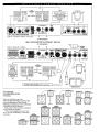
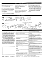
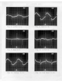
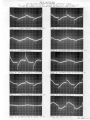
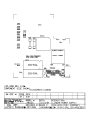
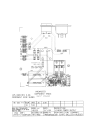
Service Manual
Micro Bass Series
Table of Contents
Operating Instructions
3
Turn On / Calibration Procedures
8
Schematics
17
Engineering Change Orders (ECOs) 33
Bill of Materials
43
MB150S Preamp Turn-On Procedure
GK Document # 420-0061-A / Preamp Board #206-0061-C
Model- MB150S- All Options
Revised 7/26/99
SETUP
1) Power switch off- connect power cord.
2) Connect “power” 3-pin connector to P1 on MB-S board so that it clicks into position.
Colors should read (L-R)- black, violet, brown. (P1 is furthest from front of panel.)
3) Connect “signal” 3-pin connector to P2 on MB-S board. Colors should read (L-R)- white, black and
red. (P2 is closer to front of panel.)
4) Connect either output to Load Box (Load A).
5) Resistance loads open (switch in center).
6) Load Box to scope-B and AC-VM.
7) Set scope switch on Load Box to look at Load A(down).
8) Probe (1:1) to scope-A and DVM. – No Gnd lead required.
9) Connect oscillator to input.
10) Set oscillator on 100Hz sine wave @ 0.5 Vrms (-6dBV).
11) DVM on 20V range.
12) AC voltmeter on 30V range.
13) Scope-A on 5V/cm, scope-B on 10V/cm.
14) Scope sweep on 2ms/cm, scope trigger on A. On MB-S Preamp set:
15) Output level to 0, switches out.
16) Contour, hi-boost to 0.
17) Volume, tones and limiter level to 10.
POWER AND LIMITER TEST
1)
2)
3)
4)
5)
6)
7)
8)
9)
10)
11)
12)
Turn on power switch.
Power LED on front panel should be lit.
Look at output- should be a clean sine wave w/ no crossover distortion, and be about 1.2Vp-p.
Flip scope switch to look at Load B (up) and see it is also 1.2Vp-p w/ no crossover distortion.
For Combo units: Switch internal speaker on, make sure disconnected. Switch off.
Change scope to 10V/cm scale.
Increase oscillator output to 160mVrms (-16dBV). Output = 14Vrms.
Engage limiter. Output falls to 11Vrms.
Decrease limiter level to 0. Output falls to 7.5Vrms.
Increase output level to 10. Output goes to 10Vrms.
Disengage limiter. Output hits rails hard.
Switch both loads to 4 ohms- signal should clip on top and bottom and then shut off after a few seconds. (May have to add 8.2 ohms
resistance).
13) Remove loads (switches to center) and set output level to 12 o’clock.
14) Turn unit off and then on again. Note how long it takes before output reappears on scope- should be no more than 2-3 seconds.
INPUT SET-UP AND SYSTEM GAIN TEST
1)
2)
3)
4)
5)
6)
7)
8)
Turn on power switch- power LED only should light.
Look at U1-U7 with probe. Adjust R13 (1K trim pot) so the signal hits the rails evenly on both sides. Signal should be about 22 V p-p.
Engage –10dB switch. Signal becomes 1.7Vrms.
Direct Out pins 2 & 3= 1.7Vrms. Disengage –10dB switch.
Oscillator to –46dBV (500mVrms).
Scope trigger to B.
Increase output level. Output should hit rails at about 3-4 o’clock.
Engage limiter. Limiter LED should light ( output raises slightly).
INPUT SET-UP AND SYSTEM GAIN TEST (contd.)
9)
10)
11)
12)
Decrease limiter level to 0. Output drops to 12Vrms.
Disengage limiter.
Look at tip of headphone jack (J4). Output should be about 4.2Vrms at this point.
Repeat step 11 looking at ring of headphone jack.
TONE CONTROLS TEST
1)
2)
3)
4)
5)
Set all large knobs to center (12 o’clock), switches out, small knobs to 0.
Set scope-B to 2V/cm and 2ms/cm
Set oscillator to 100Hz square wave at –46dBV.
Look at output, compare to Figure 1.
One at a time turn tone control knobs and compare outputs ( resetting to center after finishing):
A) Treble to 10- Fig. 2; Treble to 0- Fig. 3
B) Hi-mid to 10- Fig. 4; Hi-mid to 0- Fig. 5
C) Lo-mid to 10- Fig. 6; Lo-mid to 0- Fig. 7
D) Bass to 10: Fig. 8; Bass to 0- Fig. 9
VOICING FILTERS TEST
1) Engage low-cut switch- compare to Fig. 10. Disengage.
2) Increase contour to 10- compare output to Fig. 11. Reset to 0.
3) Increase hi- boost to 10- compare output to Fig. 12. Reset to 0.
NOISE TEST
1)
2)
3)
4)
5)
6)
7)
Remove oscillator input.
Turn large front panel knobs to 10, small knobs to 0, switches out.
Connect speaker to output and listen for noise, sound should be clean, no crackling or distortion.
Change AC voltmeter range to 0.1V.
Noise should measure less than 60mV.
AC voltmeter to 0.3V range.
Engage low-cut, hi-boost and contour to 10. Noise < 300 mVrms.
RETURN KNOBS TO ZERO- READY FOR BURN-IN.
MB150E Preamp Turn-On Procedure
GK Document #: 420-0087-A / Preamp Board # 206-0087-B
Model #’s: MB150E- All options
Rev. 7/27/99
SETUP
1) Power switch off - connect power cord.
2) Connect “power” 3-pin connector from power amp to connector P1 on MB-E board. The colors should read (bottom-top): black, violet,
and brown. (P1 is closest to front of panel.)
3) Connect “signal” 3-pin connector from power amp to connector P2 on MB-E board. These colors should read (bottom-top): white, black
and red. (P2 is furthest from front of panel). Colors should be clearly marked on board.
4) Connect either output to load box (Load A).
5) Resistance loads open (switch in center).
6) Load box to scope-B and AC-VM.
7) Set scope switch on load box to look at Load-A (down).
8) Probe (1:1) to scope-A and DVM. (No GND lead required.)
9) Connect oscillator to input.
10) Set oscillator on 100Hz sine wave @ 0.5Vrms.
11) DVM on 20V (AC) range.
12) AC voltmeter on 30V range.
13) Scope-A on 5V/cm, scope-B on 10V/cm.
14) Scope sweep on 1ms/cm, scope trigger on A.
15) Output level to 0,, switches out.
16) Contour, hi-boost, boost to 0.
17) Volume, tones, and limiter to 10.
POWER AND LIMITER TEST
1)
2)
3)
4)
5)
6)
7)
8)
9)
10)
11)
Turn on power switch.
Disengage switches on RF2 so that LED’s are off. Only the power LED should be lit.
Look at output- should be clean sine wave w/ no crossover distortion, and be about 0.6Vp-p.
For Combo units: switch on internal speaker and make sure it’s connected. Turn off.
Change scope to 10V/cm scale.
Increase oscillator output to 160mVrms (-16dBV). Output = 21Vrms.
Engage limiter. Output falls to 14Vrms.
Decrease limiter level to 0. Output falls to 8.5Vrms.
Increase output level to 10. Output goes to 11.5Vrms.
Disengage limiter. Output should hit rails hard.
Switch both loads to 4 ohms- signal should clip on top and bottom, and then shut off after a few seconds. (May have to add 8.2 ohms
resistance.)
12) Remove loads (switches to center) and set output levels to 12 o’clock.
13) Turn unit off and then on again. Note how long it takes before output appears on scope- should be no more than 2-3 seconds.
INPUT SET-UP AND SYSTEM GAIN TEST
1)
2)
3)
4)
5)
6)
7)
Turn on power switch- power LED only should light.
Look at U1-1 with probe. Adjust R13 (1K trim pot) so signal hits the rails evenly on both side. Signal should be about 22Vp-p.
Engage –10dB switch. U1-1 becomes 1.7Vrms. Disengage –10dB switch.
Scope trigger to B. Set oscillator to –46dBV (5mVrms).
Output level to 10. Output should be about 8Vrms.
Engage limiter. Limiter LED should light. (Output raises slightly.)
Decrease limiter to 0. Output drops to 6Vrms.
INPUT SET-UP AND SYSTEM GAIN TEST(contd.)
8) Disengage limiter.
9) Look at tip of headphone output jack (J4). Output should be about 1Vrms at this point.
10) Repeat step 9 looking at ring of headphone output jack.
TONE CONTROLS TEST
1)
2)
3)
4)
5)
Set all large knobs to center (12 o’clock), switches out, small knobs to 0.
Set scope-B to 1V/cm and 2ms/cm.
Set oscillator to 100Hz square wave at –46dBV.
Look at output, compare to Fig. 1.
One at a time, turn tone control knobs and compare output to figures (resetting each to center after finishing):
A) Treble to 10- Fig. 2; Treble to 0- Fig. 3.
B) Hi-mid freq. and level to 10- Fig. 4.
C) Hi-mid to 0, level 10- Fig. 5.
D) Hi-mid to 0, freq. on 0- Fig. 6.
E) Lo-mid freq. and level to 10- Fig. 7.
F) Lo- mid freq. to 0, level on 10- Fig. 8.
G) Lo-mid level to 0, freq. on 0- Fig. 9.
H) Bass to 10- Fig. 10; Bass to 0- Fig. 11.
VOICING FILTERS TEST
1) Engage low-cut switch- compare to Fig. 12. Disengage.
2) Increase contour to 10- compare to Fig. 13. Turn to 0.
3) Increase hi-boost to 10- compare to Fig. 14. Turn to 0.
BOOST / CHORUS / BALANCED OUTPUTS TEST
1)
2)
3)
4)
5)
6)
7)
8)
9)
10)
11)
Increase boost to 10- compare to Fig. 15. Turn to 0.
Change scope trigger to A and scope-A to 0.1V/cm range.
Look at direct out (J4) pins 2,3 - compare to Fig. 16.
Engage chorus switch with rate and depth to 0.
Look at balance out-R(J3) pin 3 (center), compare to Fig. 17.
It should have a small spike that moves back and forth approx. 1 division every 2-3 seconds.
Increase rate to max. and spike travel should speed up to about once every .7 seconds. Rate to 0.
Increase depth to max. and the spike should travel back and forth about 5 divisions. Depth to 0.
Look at balance out-R pin 2(left). Spike should be slightly smaller than that in Fig. 17.
Engage 1-2 switch (S5)- J3 pin 3 changes, J3 pin 2 stays the same.
Compare balance out-L(J4) pins 2-3 to Fig. 17.
FOOTSWITCH TEST
1)
2)
3)
4)
5)
6)
7)
8)
9)
Set scope-B to 2V/cm, trigger to B.
Connect RF2 to footswitch jack (J8) using stereo cord.
Set boost to max and chorus switch in on front panel.
Set RF2 switches so LED’s are off - compare to Fig. 1.
Engage boost switch. Boost LED should light on footswitch.
Compare output to Fig. 15. Disengage boost switch.
Engage chorus switch. LED should light on RF2 and on front panel.
Compare output to Fig. 18. Disengage chorus switch.
Remove footswitch, set boost to 0.
RETURN AND STEREO AUX IN TEST
1)
2)
3)
4)
5)
6)
Set AC-VM to 10V scale.
Set oscillator to 100 sine wave at –26dBV (50mV).
Insert plug from oscillator into return jack (J6).
Set output to 10. Output = 2Vrms.
Insert plug from oscillator half-way into stereo aux. in jack (J5). Output = 3.5Vrms.
Push plug in rest of way. Output should be same as above.
NOISE TEST
1)
2)
3)
4)
5)
6)
7)
8)
Remove oscillator input.
Turn large knobs to 10, small knobs to 0, switches out.
Connect speaker to output, listen for noise. It should be clean with no crackling or distortion.
Change AC-VM range to 0.1V.
Noise should measure less than 30mV.
Engage low-cut, hi-boost and contour to 10. Noise < 150mVrms.
Voicing filters off or to 0, boost to 10, chorus on.
Noise < 200mVrms.
RETURN KNOBS TO ZERO- READY FOR BURN-IN