1
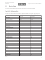
SIPLACE WPC 80F type 3
Service Manual
09/1997 Edition
(The reproduction, transmission or use of this document or its
contents is not permitted without written authority.
Offenders will be liable for damages. All rights, including rights
created by patent grant or registration of a utility model or design,
are reserved.)
(We have checked the contents of the printed document to ensure that
it is in agreement with the hardware and software described therein.
However, since discrepancies cannot be ruled out, we cannot assume
responsibility for complete agreement.
The information given in this printed document is however regularly
reviewed and necessary corrections included in subsequent editions.
We would appreciate any suggestions for improvements.)
SIEMENS AG 1997 All rights reserved
Subject to change without prior notice
Order No.: xxxxxxxx-xx
Siemens Aktiengesellschaft
To be ordered from:
SIEMENS L&A
Electronic Assembly Systems
Rupert-Mayer-Strasse 44
D - 81359 Muenchen
Printed in the Federal Republic of Germany.
Service Manual SIPLACE 80S-20/F4
Edition 03/97
t
I
Content
Page
1 Introduction . . . . . . . . . . . . . . . . . . . . . . . . . . . . . . . . . . . . . . . . . . . . . . . . . . . . . . . . . . . . . . . . . . . . . . . . . 1
1.1 General Comments . . . . . . . . . . . . . . . . . . . . . . . . . . . . . . . . . . . . . . . . . . . . . . . . . . . . . . . 1
1.2 Safety Instructions . . . . . . . . . . . . . . . . . . . . . . . . . . . . . . . . . . . . . . . . . . . . . . . . . . . . . . . . 1
2 Integration into the SIPLACE Placement Machine . . . . . . . . . . . . . . . . . . . . . . . . . . . . . . . . . . . . . . . . . 2
2.1 Interfaces with the SIPLACE 80F . . . . . . . . . . . . . . . . . . . . . . . . . . . . . . . . . . . . . . . . . . . . . 2
2.1.1 RS 232 (V24) Interface . . . . . . . . . . . . . . . . . . . . . . . . . . . . . . . . . . . . . . . . . . . . . . . . . . . 2
2.1.2 380 V Power Supply . . . . . . . . . . . . . . . . . . . . . . . . . . . . . . . . . . . . . . . . . . . . . . . . . . . . . 2
2.1.3 EMERGENCY STOP Interface . . . . . . . . . . . . . . . . . . . . . . . . . . . . . . . . . . . . . . . . . . . . . 2
2.2 Machine Data . . . . . . . . . . . . . . . . . . . . . . . . . . . . . . . . . . . . . . . . . . . . . . . . . . . . . . . . . . . . 3
3 Design and Method of Operation . . . . . . . . . . . . . . . . . . . . . . . . . . . . . . . . . . . . . . . . . . . . . . . . . . . . . . . 4
3.1 Reference Point Run . . . . . . . . . . . . . . . . . . . . . . . . . . . . . . . . . . . . . . . . . . . . . . . . . . . . . . 6
3.2 Modules of the Control System . . . . . . . . . . . . . . . . . . . . . . . . . . . . . . . . . . . . . . . . . . . . . . 7
3.3 Control Unit Y1 . . . . . . . . . . . . . . . . . . . . . . . . . . . . . . . . . . . . . . . . . . . . . . . . . . . . . . . . . . . 8
3.3.1 Machine Controller . . . . . . . . . . . . . . . . . . . . . . . . . . . . . . . . . . . . . . . . . . . . . . . . . . . . . . 8
3.3.2 Axis Board . . . . . . . . . . . . . . . . . . . . . . . . . . . . . . . . . . . . . . . . . . . . . . . . . . . . . . . . . . . . . 8
3.3.3 5 V, + 15 V, 24 V Power Supply Unit. . . . . . . . . . . . . . . . . . . . . . . . . . . . . . . . . . . . . . . . . 9
3.3.4 Servo Boards. . . . . . . . . . . . . . . . . . . . . . . . . . . . . . . . . . . . . . . . . . . . . . . . . . . . . . . . . . . 9
3.3.5 Ballast Circuit. . . . . . . . . . . . . . . . . . . . . . . . . . . . . . . . . . . . . . . . . . . . . . . . . . . . . . . . . . . 9
3.4 Mounting Plate Y2 . . . . . . . . . . . . . . . . . . . . . . . . . . . . . . . . . . . . . . . . . . . . . . . . . . . . . . . 10
4 Feed Axis . . . . . . . . . . . . . . . . . . . . . . . . . . . . . . . . . . . . . . . . . . . . . . . . . . . . . . . . . . . . . . . . . . . . . . . . . . 13
4.1 Adjusting and Testing . . . . . . . . . . . . . . . . . . . . . . . . . . . . . . . . . . . . . . . . . . . . . . . . . . . . . 14
4.1.1 Zero Point Correction . . . . . . . . . . . . . . . . . . . . . . . . . . . . . . . . . . . . . . . . . . . . . . . . . . . 14
4.1.2 Adjusting the Beros and Limit Switches . . . . . . . . . . . . . . . . . . . . . . . . . . . . . . . . . . . . . 15
4.1.3 Electrical Adjustment . . . . . . . . . . . . . . . . . . . . . . . . . . . . . . . . . . . . . . . . . . . . . . . . . . . . 16
4.1.4 Setting the crash light barrier: . . . . . . . . . . . . . . . . . . . . . . . . . . . . . . . . . . . . . . . . . . . . . 19
5 Lifting Axis . . . . . . . . . . . . . . . . . . . . . . . . . . . . . . . . . . . . . . . . . . . . . . . . . . . . . . . . . . . . . . . . . . . . . . . . 20
5.1 Adjusting and Testing . . . . . . . . . . . . . . . . . . . . . . . . . . . . . . . . . . . . . . . . . . . . . . . . . . . . . 21
5.1.1 Zero Point Correction . . . . . . . . . . . . . . . . . . . . . . . . . . . . . . . . . . . . . . . . . . . . . . . . . . . 21
5.1.2 Adjusting the Beros and Limit Switches . . . . . . . . . . . . . . . . . . . . . . . . . . . . . . . . . . . . . 22
5.1.3 Electrical Adjustment . . . . . . . . . . . . . . . . . . . . . . . . . . . . . . . . . . . . . . . . . . . . . . . . . . . . 22
6 Fault Description. . . . . . . . . . . . . . . . . . . . . . . . . . . . . . . . . . . . . . . . . . . . . . . . . . . . . . . . . . . . . . . . . . . . 24
6.1 Errors with Error Messages . . . . . . . . . . . . . . . . . . . . . . . . . . . . . . . . . . . . . . . . . . . . . . . . 24
6.1.1 General Errors . . . . . . . . . . . . . . . . . . . . . . . . . . . . . . . . . . . . . . . . . . . . . . . . . . . . . . . . . 24
6.1.2 Feed Axis Errors . . . . . . . . . . . . . . . . . . . . . . . . . . . . . . . . . . . . . . . . . . . . . . . . . . . . . . . 26
6.1.3 Lifting Axis Errors: . . . . . . . . . . . . . . . . . . . . . . . . . . . . . . . . . . . . . . . . . . . . . . . . . . . . . . 29
6.2 Menu Items in the Version 100.04 Test Program . . . . . . . . . . . . . . . . . . . . . . . . . . . . . . . . 33
0-I
WPC 80F Type 3 Service Manual
Edition 09/97
I
1
Introduction
1.1
General Comments
t
I
1 Introduction
The layout of the control system of the wafflepack changer is for the most part identical to that of the SIPLACE
80F machines.
Modules which are also found in the SIPLACE 80F machine will not be described in more detail here.
If adjustment work is analogous to that for the SIPLACE 80F it will only be described in broad outline.
1.2
Safety Instructions
WARNING OO
The SIPLACE 80F placement machine and the wafflepack changer are supplied with heavy current 3 x 380 V
main power voltage. Parts of this machine will therefore be conducting dangerous voltages even when the
main switch is switched off. You must comply with the relevant VDE, VDI, VGB regulations and all applicable
provisions of federal, state and local safety laws.
Before you carry out any work on the electrical systems switch the machine off and pull out the power supply
plug.
You must comply with the accident prevention regulations applicable to working with the machine and also
with the relevant user‘s manuals (“User‘s Manual SMD Placement Machine SIPLACE 80S/F/G“). This applies
particularly to the travel ranges of the two axis positioning systems of the machine.
It is essential that you carry out the work in the same order as is specified here if injury and / or damage to
property is to be avoided.
1
I
2 Integration into the SIPLACE Placement Machine
2
t
I
WPC 80F Type 3 Service Manual
Edition 09/97
Integration into the SIPLACE Placement Machine
The wafflepack changer expands the component feed capacity of a SIPLACE 80Fplacement machine by 28
wafflepack trays.
Programming the Type 3 WPC 80F is also integrated into the line computer software of a SIPLACE line.
The Type 3 WPC 80F is activated in the line computer software via the configuration editor. Note that a description of using each software version is provided in the corresponding line computer user‘s manual.
The components are assigned to the wafflepack trays at location 1 of the conveyor editor.
Here too the software versions vary in how they are used and you should refer to the corresponding line computer user‘s manual.
The Type 3 WPC 80F is operated via the SIPLACE 80F by means of an extended single functions menu.
The precise position of the Type 3 WPC 80F in the SIPLACE 80F is determined with the vision system during
the reference point run. The fiducial is located on the right-hand pusher of the feed axis.
2.1
Interfaces with the SIPLACE 80F
2.1.1
RS 232 (V24) Interface
All commands from the SIPLACE line computer are output via this interface.
Example: reference point run and set-up data input.
2.1.2
380 V Power Supply
The Type 3 WPC 80F is supplied with 380 V via cable Y4W1 from the SIPLACE 80F.
2.1.3
EMERGENCY STOP Interface
The Type 3 WPC 80F is also integrated into the emergency stop circuit of the SIPLACE 80F. A check-back
signal is returned from this emergency stop circuit in the form of an alternating voltage of 24 V which switches
on the control unit in the Type 3 WPC 80F.
The contactors switch off the servo voltage (90 - 100 V). In addition the power supply to the brake is switched
off after a brief delay.
The break contact of the emergency stop button is integrated into the safety circuitry of the SIPLACE 80F - it
is hard-wired to an input.
If the EMERGENCY STOP loop in a machine is interrupted (by the EMERGENCY STOP button) the control
system for the entire station will drop out.
If the guard is opened only the control voltage of the Type 3 WPC 80F will switch out.
2
WPC 80F Type 3 Service Manual
Edition 09/97
2.2
I
t
I
2 Integration into the SIPLACE Placement Machine
Machine Data
The machine data are kept in a RAM facility with back-up battery in the machine controller.
Type 3 WPC 80F Machine Data:
The items which may have to be changed during adjustment work are shown against a gray background.
Feed axis
Lifting axis
Axis number
0
1
Zero point correction
-1665
-3558
Maximum position
38668
239523
Minimum position
-75
-778
Speed correction
20
10
Force correction
99
99
Type of force
0
0
Reference point speed
2
6
Minimum speed
3
3
Minimum section acceleration
1
100
Rounding constant
15
25
Rounding path 1
4000
500
Rounding path 2
8000
10000
Rounding constant 1
25
50
Rounding constant 2
20
45
Speed factor
14764
1514
Reference point run
0
0
Starting speed
3
3
Maximum deviation
10
25
P factor
2
2
I factor
2
2
Mode 1
0
0
Mode 2
0
0
Mode 3
1
0
Positioning force
99
99
Standstill time
0
0
Reduced force
30
20
Tab. 2.1
3
I
3 Design and Method of Operation
t
I
WPC 80F Type 3 Service Manual
Edition 09/97
Positions of the feed axis:
Transfer position
38639
δ position
52
Transfer position gap
130
Tab. 2.2
Positions of lifting axis:
Refill position
3000
δ conveyor area
250
Conveyor position
238680
Tab. 2.3
These machine data can be modified with the aid of version V100.06 or later of the WPCTEST testing program
(item number 00710199-06). These are the parameters:
-
Zero point correction for the lifting axis
Zero point correction of the feed axis
Minimum and maximum position of the lifting axis
Minimum and maximum position of the feed axis
Transfer position of the feed axis
The remaining machine data are protected by password since they contain parameters which have been defined by SIEMENS.
3
Design and Method of Operation
When installed in the SIPLACE machine the wafflepack changer (also referred to as the WPC 80F) expands
the component-supplying capacity of an individual SIPLACE machine by 28 wafflepack trays.
Due to its special design the changeover times for the individual wafflepacks (wafflepack trays) are very short.
In practice, changeover times of less than 3 sec. are possible. A fast/slow switch can be used to reduce the
acceleration on the horizontal axis when especially light or sensitive components are to be handled.
4
I
WPC 80F Type 3 Service Manual
Edition 09/97
t
3 Design and Method of Operation
I
Power supply
5V
SIPLACE
RS 232
15V -15V 24V
Machine controller A18
80F
SMP bus
Axis board
EMERGENCY STOP
circuit SIPLACE 80F
EMERGENCY
Servo
Servo
M
M
T
T
Sensors
STOP interface
Brake
Feed axis
Fig. 3.1
Lifting axis
Function groups of the WPC 80F or F3 control system
The set-up for the Type 3 WPC 80F is also included in the line computer software of a SIPLACE line.
The hardware of the machine itself consists of a tray storage unit with a capacity of 28 channels. Depending
on the size of the magazines, the individual channels can be occupied mehrfach and with different components. Multiple assignment of the individual channels with varying components is possible. The complete tray
storage unit is moved vertically by a lifting axis in order to bring the magazine required up to the level of the
feed axis. The lifting axis drive unit consists of a direct current servo system and a step-down ball-screw drive.
The tray storage unit runs on prisms, thus allowing precise mechanical positioning. The servo motor is equipped with a mechanical brake to prevent the lifting axis drifting out of position when the machine is switched off.
The brake is applied automatically when the servo motor is isolated or switched off. The feed axis is used for
moving horizontally the wafflepack tray in question. The conveyor consists of a direct current servo system
which uses a belt and a pusher to move the wafflepack tray into the SIPLACE 80F.
5
I
3 Design and Method of Operation
3.1
t
I
WPC 80F Type 3 Service Manual
Edition 09/97
Reference Point Run
As with the SIPLACE machine, the servo axes will have to carry out a reference point run when the Type 3
WPC 80F is switched on. This run is coupled up with the SIPLACE 80F‘s reference point run and is performed
simultaneously. If the station computer is reset, it will also be repeated. The order in which the lifting and feed
axes make their runs depends on the position of the feed axis. If the feed axis is at the stack (bero activated)
the lifting axis will start first; if the feed axis is outside the stack, it will carry out its reference run first.
The actual reference run of an individual servo axis takes this form:
-
Travel in the negative direction until the reference point switch or the reference point bero is activated
Travel in the positive direction until the first zero pulse (rotary encoder!) is found.
Load the current zero point correction into the position counter.
Travel to the reference point equal to zero on the position counter.
The procedure with the reference point switch is required due to the fact that the zero pulses of the incremental
shaft encoder repeat with every revolution and thus appear repeatedly within the possible travel range.
Once both reference points have been found, a search will also be made for the position of the tray in the SIPLACE 80F. Here the first tray will be moved to the position for transfer to the SIPLACE 80F. The SIPACE 80F
then looks for the fiducial which is to be found on the right-hand pusher. The fiducial position found is used later
in determining the pick-up position of the components. Of course this fiducial must be included in the line computer‘s MVS file.
6
WPC 80F Type 3 Service Manual
Edition 09/97
I
t
I
3.2
Modules of the Control System
Fig. 3.2
Overall view of the Type 3 WPC 80F
3 Design and Method of Operation
Key:
1) Front view
2) Viewed from above
3) Viewed from the back (voltages from the power supply unit can be measured ).
7
I
3 Design and Method of Operation
3.3
t
I
WPC 80F Type 3 Service Manual
Edition 09/97
Control Unit Y1
The following modules are accommodated in the control unit :
-
3.3.1
Machine controller with RS232 interface
Axis controller for lifting axis and feed axis
5 V, + 15 V, + 24 V power supply
Lifting axis brake controller (on the axis rear panel)
Lifting axis ballast circuit
Servo boards for feed and lifting axes
Reactance coils for the motor feed lines L1, L2, L3, L4
Machine Controller
Duties:
-
Communication with the SIPLACE 80F station computer
Data exchange with the axis controller
Memory storage for machine data (RAM with back-up battery)
Inputs for sensors
The program for the machine controller is held in EPROM. You can check the EPROM version under the menu
item Version.
The machine data and the set-up are held in RAM memory. If the machine is switched off the data are saved
by means of a back-up battery. (The battery is located behind the front panel).
The machine controller contains a gold capacitor (33 mF) which can hold the machine data even in the absence
of an external back-up battery (in other words, even when the board has been disconnected). The battery can
retain the data for a period of between several hours to several days.
Sensors: The reference point bero and the limit switches are wired into the machine controller and into the axis
board.
3.3.2
Axis Board
The axis controller of the Type 3 WPC 80F has the same design as the axis boards of the SIPLACE machines.
The Type 3 WPC 80F will only function with EPROMs of version 3.4 or later.
8
WPC 80F Type 3 Service Manual
Edition 09/97
3.3.3
I
t
I
3 Design and Method of Operation
5 V, + 15 V, 24 V Power Supply Unit
The voltages are routed to the modules in the control unit via the SMP bus on the rear panel of the control unit.
The following modules require 5 V direct current.
- Incremental shaft encoders
- Machine controllers
- Axis board
The following modules require + 15 V direct current :
- Machine controller (RS232)
- Axis board
- Servo cards
The voltages can be checked at the back of the control unit (see Fig. 3.2).
3.3.4
Servo Boards
The servo boards for the lifting and feed axes have the same design as the x-axis servo of the SIPLACE 80F,
differing only in the dimensioning of the PI controller.
3.3.5
Ballast Circuit
The task of the ballast circuit is to compensate for the energy created during the downward movement of the
lifting axis. At approximately 140 V it switches ballast resistors into the power supply to the servo board.
9
I
3 Design and Method of Operation
3.4
t
WPC 80F Type 3 Service Manual
Edition 09/97
I
Mounting Plate Y2
length 500
Fig. 3.3
Mounting plate Y2
The mounting plate accommodates the following modules:
- 24 V rectifier
- Grounding terminal strip
- 24 V distributor inputs
Diagram 3.3 shows the layout of control unit Y2.
The incoming unit accommodates the following modules:
-
10
Main fuse F1
Grounding terminal strip
3 x 380 V or 3 x 230 V transformers (the USA version is connected differently)
Emergency stop circuit (contactor safety protection unit or two AC contactors)
F2 fuse for the power supply to the servo boards (90 - 100 V)
Terminals
length 220
length 220
Distributor
length 245
Inputs
PE rail
length 500
WPC 80F Type 3 Service Manual
Edition 09/97
Fig. 3.4
I
t
I
3 Design and Method of Operation
Overall circuit diagram
Overall circuit diagram: With some machines the lifting axis motor was connected directly to the control /servo
unit. With this type of machines you must also fit cable Y255 which is also supplied when you replace the
motor of the lifting axis. (Plug X8 plugs directly into the motor).
11
I
3 Design and Method of Operation
Fig. 3.5
12
Control and servo unit
t
I
WPC 80F Type 3 Service Manual
Edition 09/97
WPC 80F Type 3 Service Manual
Edition 09/97
4
I
t
I
4 Feed Axis
Feed Axis
The feed axis consists of a direct current servo system with belt drive. The wafflepack trays are transported by
the pushers from the storage unit into the pick-up area of the SIPLACE 80F. For this purpose two lateral
grooves are provided in the wafflepack trays.
Fig. 4.1
Feed axis (viewed from above)
Key:
1) AY-B2 tray supplied
2) AY-S2 limit switch
3) AY-B6 transmitter for crash light barrier
4) AY-B1feed axis reference point
5) AY-S1 feed axis limit switch
6) AY-B3 tray in magazine
7) AY-B5 receiver for crash light barrier
8) Fast/slow switch
9) EMERGENCY STOP switch
The pusher drive consists of one belt which is driven via a connecting shaft. The pusher is attached to the end
of the belt. The connecting shaft is driven by an endless belt running off the motor.
13
I
4 Feed Axis
t
I
WPC 80F Type 3 Service Manual
Edition 09/97
The belt can be tensioned by means of slots in the motor bracket or in the rear deflection bearing.
The reference point bero monitors the position of the pusher when the storage unit moves (lifting axis). The
zero pulse of the incremental encoder appears repeatedly in the travel range of the axis. For this reason the
reference switch is approached first during the reference point run, after which the first zero pulse of the incremental encoder is sought. (Reference point run with reference point switch).
Transfer position:
The transfer position is the position of the feed axis of the wafflepack tray when it has been brought up to the
SIPLACE 80F. The transfer position is held in the machine data in the WPC 80F. A bero is fitted for the purpose
of monitoring the wafflepack tray in the transfer position. In the transfer position the wafflepack tray must press
lightly against the spring plate stops.
You can reduce the acceleration of the feed axis by pressing the slow key. This is necessary to prevent small
components in the wafflepack tray from slipping.
When the wafflepack tray moves back to the storage unit the feed axis first positions itself at - 52 digits and
then at 0 digits. This ensures that when the lifting axis moves the pushers of the feed axis will be located precisely in the center of the groove in the wafflepack tray.
4.1
Adjusting and Testing
CAUTION O
Do not carry out adjustment work with the wafflepack tray in the storage unit.
NOTE
You will need the WPC 80F test program for adjustment of the machine (item no. 00710199-06) as well as the
corresponding user‘s manual (item no. 00190799-01).
4.1.1
Zero Point Correction
The reference point is determined with the aid of zero point correction. At the reference point the pusher will
be located precisely in the center of the groove of the wafflepack tray in the storage unit. Only in this position
is the lifting axis permitted to move.
14
WPC 80F Type 3 Service Manual
Edition 09/97
I
t
I
4 Feed Axis
!
WARNING OO
The lifting axis must be located on a track position in order to be able to record the feed axis zero point correction.
Setting the zero offset:
Reference the feed axis with the magazine plate inserted.
Disable the axis. Manually move the axis with the magazine plate until it is 0.2 mm away from the front vertical
guide rails. Move the pusher into the middle of the recess in the magazine plate. Accept the zero offset value.
CAUTION O
An incorrectly set reference point may result in a crash with the magazine carriers in the store.
Once you have modified the zero offset, you must also make the following changes:
- 1. Check the reference BERO:
The reference BERO must be active in the reference point. When moving back, the reference point
BERO must not switch until the vertical axis can move with the frame.
-
2. Correct the transfer position (position of the frame supplied)
3. Check the rear limit switch: (maximum travel)
4. Check the front limit switch: (minimum travel)
Check the maximum and minimum travel. The minimum travel must be at least -52 digits.
The response of the reference point BERO and the limit switch can be set by moving the actuator on
the magazine carriage.
ATTENTION
The value of the minimum travel must be a negative value. Once you have set the zero offset, the value may
be positive, in which case, an “Error in the feed axis” message will appear.
Hint: Enter a negative value of -100 digits in the machine data and then continue.
4.1.2
Adjusting the Beros and Limit Switches
Adjusting the feed axis reference point bero Ay-B1:
In the Feed axis column select the menu item Adjust reference point bero and with the aid of the test program adjust the actuating element of the reference point bero.
If the operating position is too small (0 - 5 digits) it is possible that the reference bero will not be actuated when
the lifting axis moves. The lifting axis will be halted and error message 538 output:
15
I
4 Feed Axis
t
I
WPC 80F Type 3 Service Manual
Edition 09/97
538: Fault in the position of the jaws (pusher)
If the operating position of the reference bero is too large (> 20 digits) a crash could occur during the reference
run. The bero should operate within the 10 - 15 digits range.
Recording the transfer position:
Setting on the WPC 80F (with 2 pushers):
Select the "Transfer position“ option from the "Feed axis“ column. Approach the transfer position with a magazine plate. The plate should press lightly against both stop springs. The program will automatically record the
value.
Setting on the WPC 80 F type 3:
Select the "Transfer position“ option from the "Feed axis“ column. Approach the transfer position without a
magazine plate (after inserting a 4 mm pin into the hole at the transfer position to act as a stop).
PLEASE NOTE
Check the transfer position. When making the setting, move the pusher against the 4 mm pin manually, if
necessary, and accept the position.
PLEASE NOTE
The transfer position MUST be set before setting the “limit switch + feed axis” since the switch position is calculated from the transfer position.
Setting the feed axis "+“ limit switch AY-S2:
First remove the magazine plate. Select the "Limit switch +“ option from the "Feed axis“ column and then set
the limit switch using the testing program.
Setting the feed axis "-“ limit switch AY-S1 :
Select the "Limit switch -“ option from the "Feed axis“ column and then set the limit switch using the program.
4.1.3
Electrical Adjustment
Tools and auxiliary materials :
-
16
Multimeter
Oscilloscope
Axis tester
Size 0 screwdriver
WPC 80F test program, version V100.05 and later
WPC 80F Type 3 Service Manual
Edition 09/97
I
t
4 Feed Axis
I
Electrical adjustments to the axis board and the servo board are carried out analogously to those for the x axis
of the SIPLACE 80F.
Adjustment work:
-
Zero adjustment of the axis controller (do this only when you change the board)
Servo amplifier offset (do this only when you change the servo board)
Tachometer adjustment
Controller optimization via P gain
1mm along the feed axis corresponds to 53.33 increments .
Adjustment values :
Adjustment parameters
Setting values
I r.m.s. (fixed)
4.3 A
Belt tension of motor drive belt
230 +/- 5 Hz
Belt tension of conveyor belt (long belt)
85 +/-2 Hz at a length of 360 mm
(see Fig. 4.2)
Speed V = 2 (track signals period)
100 µs (+ 2 µs)
Positioning time 0 - 30000 dig V = 10
approx. 1150 ms (guideline value)
Tab. 4.1
Fig. 4.2
Adjusting the belt tension
17
I
4 Feed Axis
t
I
WPC 80F Type 3 Service Manual
Edition 09/97
Zero adjustment of the axis controller:
NOTE
With this zero adjustment a reference run should not be carried out for the axes. The machine must have
been switched on at least 20 minutes before the adjustment work begins.
NOTE
This zero adjustment is required for both axes and is carried out in the same manner for both axes. Zero adjustment must be carried out before all other adjustment work on the axes.
●
Connect the axis tester to the interface (front panel) of the axis board.
●
Connect a digital multimeter to the sockets for the ‚nominal value‘ at the back of the axis tester.
●
Switch the axis selector switch to the axis which is to be tested.
●
Set the setpoint potentiometer on the front of the axis board to 0 volts.
●
Set the power potentiometer on the front of the axis board to 0 volts.
Adjusting the offset at the servo
●
Allow the machine to warm up (at least 20 minutes after switching on) before making any adjustments.
●
Set Kl in the machine data to 0 and the position deviation to 100 before adjusting the offset of both
axes. (You will need to enter your password.)
●
After positioning to a specific position (see Table 4.1) adjust the offset at standstill to setpoint position
+/- 1 digit.
NOTE
If the axes are modified, carry out a reference point run.
Adjusting the speed at the servo:
With the help of the oscilloscope under the menu item Set tachometer adjust the speed in a way that when a
speed of V = 2 is added to the machine data the period amounts to 100 µs (+ 2 µs) .
Connect the axis testing box. Set the axis selector switch to axis 0. Connect track signals A and B on the axis
testing box to the oscilloscope.
PLEASE NOTE
The preset guideline value of 1150 ms corresponds to a period of 100 (+ 2µs) .
Setting the P gain on the servo:
Set the P gain so that no overshooting or humming occurs at the axis.
18
WPC 80F Type 3 Service Manual
Edition 09/97
4.1.4
I
t
I
4 Feed Axis
Setting the crash light barrier:
There is a crash light barrier in the middle of the feed axis. Set the pass-through height to 15 mm. If a tray is
raised by the IC head, the light barrier will respond when the tray is brought in and the feed axis will be stopped.
19
I
5 Lifting Axis
t
5
Lifting Axis
Fig. 5.1
Lifting axis (side view)
I
WPC 80F Type 3 Service Manual
Edition 09/97
The drive unit of the lifting axis consists of a direct current servo system with step-down spindle drive. The
storage unit runs on two prism guides.
When the wafflepack tray is moved into or out of the storage unit the lifting axis is lowered by 0.4 mm and then
raised again to make movement in either direction easier.
The lifting axis is equipped with a brake which is mounted on the motor shaft. The brake is activated when the
machine is switched off or the axis is isolated.
DANGER
OOO
Before you do any work on the lifting axis motor (for example, to change the belt or the motor) you must first
move the lifting axis down to its lower position as otherwise the brake will have no effect and the lifting axis will
drop immediately. RISK OF INJURY.
When in operation the lifting axis is isolated after reaching this position and the brake is activated. The brake
20
WPC 80F Type 3 Service Manual
Edition 09/97
I
t
I
5 Lifting Axis
is operated at the axis board via a relay (servo controller release, brake on).
The servo release signal is given with an OFF delay (C2, R4) in order to bridge the response time of the brake.
Function of the two buttons on the control / servo unit:
Bridge the limit switches: Disables the limit switches.
Isolate brake:
WARNING OO
If the brake is disabled the axis will drop - there may be a collision of the wafflepack tray and the pusher.
5.1
Adjusting and Testing
CAUTION O
Remove the wafflepack tray from the storage unit before making any adjustments.
5.1.1
Zero Point Correction
The reference point of the lifting axis is the transfer position of the lowest wafflepack tray. The lower edge of
the first wafflepack tray is at the same height as the slide guideway of the feed axis.
CAUTION O
An incorrectly set reference point can result in the wafflepack tray jamming in the feed axis or the guide rails.
If necessary, modify the zero point correction.
After modifying the zero point correction you must check the minimum and maximum travel paths.
21
I
5 Lifting Axis
t
I
WPC 80F Type 3 Service Manual
Edition 09/97
Recording the lifting axis zero point
Select the menu item Zero point correction in the Lifting axis column. Now press F4 to go to Inch lifting
axis. Inch the lifting axis until the guide rails of the feed axis and the footprint area of the first storage unit position are parallel. Use a straight-edge to check this.
Now quit Inch lifting axis and press F3 to accept this value. If the zero point correction value is greater than
4000 it can only be added manually to the machine data. After that, make a reference run.
5.1.2
Adjusting the Beros and Limit Switches
Adjusting the reference point bero
Select the menu item Set reference point in the Lifting axis column and use the program to adjust the reference point BY-B1.
This adjustment is needed to prevent the zero pulse of the incremental encoder from coinciding with the switching point of the bero (this can lead to different reference points).
Adjusting the lifting axis limit switches „+“ BY-S2 and „-“ BY-S1
Select the menu item Limit switch (X) in the Lifting axis column and use the program to adjust the limit switch
in question.
NOTE
If the error message „Limit switch loop open“ is displayed the limit switch is responding too early (in other
words, the limit switch projects into the travel range of the axis in question).
In the case of the error message „Axis on the buffer“ the limit switch is responding too late (in other words, the
limit switch is located too far outside the travel range of the axis in question).
Now make a reference run with the lifting axis. To allow you to move the lifting axis away from the lower limit
switch the lifting axis limit switch loop can be bridged by pressing the button Lifting axis limit switch.
5.1.3
Electrical Adjustment
Tools and auxiliary materials :
-
22
Multimeter
Oscilloscope
Size 0 screwdriver
SIPLACE axis tester
WPC 80F test program
WPC 80F Type 3 Service Manual
Edition 09/97
I
t
5 Lifting Axis
I
Electrical adjustments to the axis board and servo are carried out analogously to those for the x axis of the
SIPLACE 80F.
The current is fixed (cannot be changed) - the current monitor checks the correct P gain.
1 mm travel corresponds to 520 increments
Adjustment values:
Adjustment parameters
Setting values
I r.m.s (fixed)
7A
Belt tension
260 +/- 10 Hz
Speed (track signals period)
95 µs (+ 2 µs)
Positioning time 0 - 200000 digits, V = 10
approx. 1200 ms (guideline value)
Tab. 5.1
Adjustment work:
-
Zero adjustment of the axis controller (do this only when you change the board)
Servo amplifier offset (do this only when you change the servo board)
Tachometer adjustment
Controller optimization via P gain
Zero adjustment of the axis controller:
See feed axis zero adjustment
Adjusting the speed at the servo
Adjust the speed with the help of the oscilloscope under the menu item Set tachometer in a way that the
period amounts 95 µs (+ 2 µs) if a speed of v = 2 is added to the machine data.
Connect the axis testing box. Set the axis selector switch to axis 0. Connect track signals A and B on the axis
testing box to the oscilloscope.
PLEASE NOTE
The preset guideline value of 1200 ms corresponds to a period of 95 (+ 2µs).
Setting the P gain on the servo:
Set the P gain so that no overshooting or humming occurs at the axis.
23
I
6 Fault Description
6
t
I
WPC 80F Type 3 Service Manual
Edition 09/97
Fault Description
The first stage in fault correction is to refer to the fault descriptions and possible causes listed below.
The possible reasons are issued in an order which corresponds to the best order to attack the problem on the
basis of the amount of work involved and the likelihood of the fault.
For more detailed information on fault locating and correction, please refer to the corresponding section of the
service manual.
DANGER
OOO
You should comply with all safety instructions in the user‘s manual while carrying out fault correction work.
6.1
Errors with Error Messages
These errors are displayed on the SIPLACE 80F station and are split into General errors, Feed axis errors
and Lifting axis errors.
6.1.1
Error 162
General Errors
WPC must be moved from the refill position.
WPC is in the refill position. Finish refill position in the window wafflepack changer.
Error 475
Communication with WPC faulty
Error already occurred during reference run: check plug connections .
Error during placement run:
The interface cable (1710 470 D0515-W1 in SIPLACE + 1710 460 Y0242-W3 in the WPC) is not connected
properly, or the cable or plug is defective -> Make sure the plug is connected properly -> Check cable for continuity (for plug assignments, see circuit diagrams folder); replace cable, if necessary.
- The power supply cable is not connected correctly, the cable or plug is defective, check the voltages in the
wafflepack changer (3 x 380 V or 3 x 220 V in the case of the US version).
- The communication module in the SIPLACE 80F4 control unit -> The plug is not properly plugged in or the
module is defective.
- The WPC A18 machine controller is defective: replace the module.
- The power supply unit in the wafflepack changer control unit is defective -> Check the voltages in the control unit (+ 5 V, + 15 V, - 15 V).
- Other electrical fault (the wafflepack changer control unit is defective: bus board or wiring -> Notify
Siemens SMD Service department.
24
WPC 80F Type 3 Service Manual
Edition 09/97
Error 522
I
t
I
6 Fault Description
Syntax error in command to WPC
Error already occurred during reference run: interface cable mixed up or restart run.
Error during placement run:
Cable break in the wafflepack changer interface cable -> Check the cable for continuity and replace, if necessary (for plug assignments, see the circuit diagrams folder).
- Check the EPROM version of the wafflepack changer machine controller (must be later than 1.2) .
- Other causes -> Notify Siemens SMD Service department.
Error 523
Command not executed, WPC not referenced
Power failure.
In the main view of the user interface select:
Conveyors -> WPC -> WPC reference run
Error 525
WPC: no tray available
The tray has not reached the delivery position. In the main view of the user interface select: Conveyors ->
WPC -> Furnish level. The tray has reached the delivery position. Fault location and correction will be carried
out by the line engineer or the service engineer.
Possible causes:
Load the WPC test program and Check inputs:
- The bero or bero cable is defective. If necessary, replace the bero and adjust the sensing distance.
- Input on controller (wafflepack changer control unit) is defective -> Measure the voltage to check the input.
if necessary, replace Controller A18.
Error 526
WPC: Sent set-up contains errors
If the fault cannot be corrected by switching the machine off and back on again,
notify Siemens SMD Service department.
Error 533
Data loss in WPC (battery defective)
- The back-up battery in the wafflepack changer control unit is flat or defective -> Replace the battery. The
battery is located in the wafflepack changer control unit behind the front panel (drawing 1710 460 Y0201
000 01 Z) -> Load the WPC test program, initialize the wafflepack changer and take over (= input manually) the wafflepack changer data from the current MA data printout at the machine. If not current MA data
are available, notify the service department.
The following data should be entered:
●
Zero point correction of the feed axis and lifting axis
●
Minimum and maximum positions of the feed and lifting axes
●
Transfer position for the feed axis
- Other defects (controller A18) -> Notify the SMD Service department.
25
I
6 Fault Description
6.1.2
t
I
WPC 80F Type 3 Service Manual
Edition 09/97
Feed Axis Errors
Error 534 WPC: Fault in feed axis (servo or axis card)
(Time-out: axis is not reaching the setpoint position).
DANGER
OOO
During all work you should comply with the DANGER texts, particularly those concerning VDE 0113 >>
Starting screen no. 4!
Further information on the error in question is provided in the WPC test program.
Possible causes (depending on error situations 1 to 3)!
With S i t u a t i o n 1:
The motor can be activated by means of a reference point run:
- The axis is stiff -> Carry out maintenance (see user’s manual).
- The axis adjustment has been carried out incorrectly or not at all -> Carry out adjustment.
- The tension of the toothed belt is incorrect -> Check with the belt tension measurement device -> Nominal
values: Lifting axis 260 +/- 10 Hz; feed axis drive belt 230 +/- 5 Hz; conveyor belt (long belt) 85 +/- 2 Hz
- The mechanism is jamming, for example the bearing is defective -> Replace the bearing.
- Drive unit or servo board is defective: Replace the drive unit or servo board and carry out adjustment of the
axis.
- The axis controller board in the wafflepack changer is not properly plugged in: Plug it in properly.
- The axis controller board in the wafflepack changer is defective: Insert a new board to test -> ATTENTION:
Set the addresses correctly first !
- Intermittent electrical contact in the motor circuit: Notify Siemens’ SMD Service department!
With S i t u a t i o n 2:
Motor can be activated but is switched off again:
NOTE:
The yellow LED is on = the r.m.s. current sensor responds: stiffness of running
- The axis runs stiffly:
●
●
No or incorrect maintenance -> maintain the axis, see user’s manual
The tension of the toothed belt is too high:
Setpoint values: Lifting axis 260 +/- 10 Hz; feed axis drive belt 230 +/- 5 Hz;
Conveyor belt (long belt) 85 +/- 2 Hz.
●
Other mechanical obstacle / mechanism is jamming : If applicable notify Siemens‘ SMD Service department !
- Only with no. 530: Error "Lifting axis fault" occurs always during downward travel: Ballast circuit is defective.
NOTE: During downward travel the ballast circuit LED flashes (if the storage unit is full).
26
WPC 80F Type 3 Service Manual
Edition 09/97
I
t
I
6 Fault Description
With S i t u a t i o n 3:
Motor cannot be activated:
DANGER
OOO
During all work you should comply with the DANGER texts, particularly those concerning VDE 0113 >> Starting screen no. 4!
- Poor connection between the servo amplifier board and the motor
- The drive motor is defective:
Check the LED on the servo amplifier board: If the red LED is on = fault (axis is switched off): Overvoltage/
servo is defective / the tacho line is interrupted / motor short-circuit to ground
- The drive unit or servo board is defective: Replace the drive unit or servo board and carry out electrical
adjustment of the axis.
- The axis controller board in the wafflepack changer has not been inserted properly: insert it firmly!
- The axis controller board in the wafflepack changer is defective: Insert a new board to test -> ATTENTION:
Set the addresses correctly first!
- The power supply to the drive unit has been interrupted: Check the servo voltage + 90 V to + 100 V at plug
X7 (at the control unit ).
- The servo board is defective -> Replace the board and carry out adjustment of the axis.
DANGER
OOO
With the following work serious physical injury may be encountered. You must NOT bridge the circuit-breaker.
All wafflepack trays must have been removed. Close the guard of the wafflepack changer.
Only with Error 539:
The brake will not release:
NOTE: You can check the functioning of the brake by pressing the Release brake button in the wafflepack
changer control unit: If the brake is defective: there is an electrical interruption (cable, plug) or the controller is
defective (board 1710460 Y0212) --> This can only be corrected by the service engineer or Siemens‘ SMD
Service department.
Error 535 WPC: Feed axis at limit switch
If the feed axis is at the limit switch :
Open the guard again, slide the axis away from the limit switch and reset the fault.
If the feed axis is not at the limit switch:
Possible causes:
S i t u a t i o n 1 Reference point run: The feed axis travels to the limit switch (operator side):
- The machine data of the feed axis are incorrect: The zero point correction is incorrect: Record with WPC
test program.
- The limit switch (rear) is not set correctly: WPC test program -> Limit switch.
- WPC test program -> Check inputs:
27
I
6 Fault Description
●
t
I
WPC 80F Type 3 Service Manual
Edition 09/97
The reference point bero has not been adjusted correctly (can be activated): WPC test program -> Menu
item Feed axis / reference bero -> Set switching position.
●
The reference point bero or the bero cable is defective. If necessary, replace the bero and adjust.
- The axis board is defective: Replace the board -> ATTENTION: Set the addresses correctly first!
- The electrical adjustment of the axis is incorrect or the servo board is defective.
S i t u a t i o n 2 During operation sequence : The front or rear limit switch is (mechanically) operated:
- Counting error in the feed axis: WPC test program -> Check feed axis / tracks -> Counting error is displayed -> If necessary, check the tracks using the oscilloscope (track missing, A and B pulse edges offset):
●
Constant counting error:
- The drive unit (incremental encoder) of the feed axis is defective.
- The axis controller board in the wafflepack changer control unit is defective: To test, insert a new board ->
ATTENTION: Set the addresses correctly on the board first.
●
Sporadic counting error: Check the screening of the motor cable (track signals).
- No counting error but the zero point of the axis has shifted:
●
The pitch of the belt has been jumped: Check the tension of the toothed belt.
●
Feed axis of incremental encoder is defective / toothed wheel is loose: If necessary, replace the drive unit
and carry out electrical adjustment of the axis.
NOTE.
The corresponding zero point correction will have to be reset after replacement of the motor (drive unit) or toothed belt.
- The machine data of the feed axis are incorrect: The zero point correction is not correct: Record with WPC
test program.
- The front limit switch (transfer end) is not set correctly: WPC test program -> Limit switch.
- The electrical adjustment of the axis is incorrect or the servo board is defective.
- Other electrical causes -> Notify Siemens‘ SMD Service department
Error 537 WPC: Feed axis servo released
The axis has been isolated at the axis controller board in the wafflepack changer -> Switch the axis on.
- The axis controller board in the wafflepack changer is defective -> Instal a new board
ATTENTION: Set the addresses correctly first (see the wafflepack changer service manual).
Error 538
WPC: Error in jaws position
NOTE: When the storage unit is moving the position of the jaws is checked.
- Load the WPC test program -> Check inputs:
●
The reference point bero or the bero cable is defective. If necessary, replace the bero and adjust the sensing distance.
●
Input at the controller (wafflepack changer control unit) is defective: Measure the voltage to check the
input. If necessary, replace controller A18.
- The reference point bero of the feed axis is not set correctly: WPC test program -> Menu item Feed axis /
reference bero -> Check the switching position, adjust if necessary.
28
WPC 80F Type 3 Service Manual
Edition 09/97
I
t
I
6 Fault Description
- The zero point correction is incorrect: record with WPC test program.
- Counting error of the feed axis: WPC test program -> Check feed axis / tracks -> Counting errors will be
displayed. If necessary, check the tracks using the oscilloscope (track missing, A and B pulse edges offset)
●
Constant counting error
- The drive unit (incremental encoder) of the feed axis is defective.
- The axis controller board in the wafflepack changer is defective: Insert a new board to test. ATTENTION:
Set the addresses correctly first!
●
Sporadic counting error: Check the screening of the motor cable (track signals).
Error 536
WPC: Axis error of feed or lifting axis
NOTE:
Load WPC test program -> Check axis errors.
Using the Feed axis function -> check Status whether Position outside travel range applies.
- The MA data of the wafflepack changer are not correct -> Correct on the basis of the current printout or
determine data with the WPC test program following fault correction work :
●
Transfer position
●
Maximum and minimum travel range
- Axis error with the feed axis during reference point run: Tray in the transfer position bero is defective.
- Other errors -> Notify Siemens‘ SMD Service department .
6.1.3
Lifting Axis Errors:
Error 539
WPC: Fault in lifting axis (servo or axis board) See Error 534
The axis board or servo of the lifting axis is defective. Replace the axis board or servo board.
Error 540
WPC: Lifting axis at limit switch (top or bottom)
Possible causes:
S i t u a t i o n 1:
The limit switch is not being operated (mechanically), the signal remains 0 (= actuated):
- The limit switch is defective or there is an electrical interruption -> If necessary, replace the limit switch.
Intermittent electrical contact in the signal line of the limit switch -> If necessary, notify the SMD Service
department.*
Situation 2
The limit switch is not being operated (mechanically), the signal = 1 (= not actuated):
NOTE :
The following causes may be present if during operation the signal state of the bero or of the limit switch was
briefly "0" (= actuated) and the machine then is once again "1" (= not actuated = normal state).
29
I
6 Fault Description
t
I
WPC 80F Type 3 Service Manual
Edition 09/97
- The corresponding axis controller board in the wafflepack changer is defective -> Insert a new board to test
-> ATTENTION: Set the addresses correctly first !
- Intermittent electrical contact in connection with the limit switch -> Notify the service engineer of Siemens‘
SMD Service department
- The axis overshoots: The electrical adjustment of the axis on the servo amplifier board is incorrect.
S i t u a t i o n 3:
The lifting axis is at the limit switch top or bottom (signal = 0 = actuated):
- Move the lifting axis away from the limit switch (top or bottom): Call the WPC test program -> Press the
Release limit switch in the control unit and keep it pressed drown -> Select Make reference run with
wafflepack changer in the WPC test program.
DANGER
OOO
To move away from the limit switch you can also use the Release brake button. An increased risk of accident
is to be encountered here! You must NOT bridge or tamper with the circuit-breaker. All wafflepack trays must
be removed. Close the guard of the wafflepack changer. ATTENTION: The lifting axis will drop.
If the fault reoccurs the causes listed below may be responsible for this:
- The lifting axis contacts the top position limit switch during its reference run: in addition, check the reference point bero of the lifting axis.
- The electrical adjustment of the axis is incorrect or the servo board is defective
- Counting error with the lifting axis: WPC test program -> Check counting error-> Counting errors will be
displayed: If necessary, check the tracks using the oscilloscope (track missing, A and B pulse edges offset):
- Constant counting error:
●
The drive unit (incremental encoder) of the lifting axis is defective.
●
The axis controller board in the wafflepack changer control unit is defective: To test insert a new board .
ATTENTION: Set the addresses correctly on the board first!
- Sporadic counting error: Check the screening of the motor cable (track signals).
- No counting error but the zero point of the axis has shifted:
●
The pitch of the belt has been jumped: Check the tension of the toothed belt. Feed axis incremental encoder is defective / toothed wheel is loose: If necessary, replace the drive unit and carry out electrical adjustment of the axis.
NOTE :
The corresponding zero point correction will have to be readjusted after replacement of the motor (drive unit)
or the toothed belt.
-
30
The machine data of the lifting axis are incorrect:
The zero point correction is not correct: Record with WPC test program.
The limit switch has not been set correctly -> WPC test program: Menu item Limit switch.
Other electrical causes -> Notify Siemens‘ SMD Service department
WPC 80F Type 3 Service Manual
Edition 09/97
Error 542
I
t
I
6 Fault Description
WPC: Lifting axis servo released
See Error 537
Error 543
WPC: Control switched off
Wafflepack changer: control is switched off
- + 24 V voltage not present in the wafflepack changer: check power supply of the wafflepack changer
- The circuit breaker is not working properly -> Notify Siemens‘ SMD Service department
Error 544
WPC: Protection at WPC open
If it is possible to close the guard: If you can close the guard this is all that needs to be done.
If it is not possible to close the guard:
There is a mechanical obstacle (for example, a component jammed between the circuit breaker and the
guard. Remove the obstacle.
Error 545
WPC: Error while transporting tray
The tray has been removed.
Replace the tray which was previously removed back in its correct position at the front of the feed axis. Make
sure this is the correct tray:
- You must ensure that the tray has the correct contents.
- The pusher of the feed axis must engage once more with the cutout in the tray.
- The magazine of the tray must not be the wrong way round (180° positioning error) as this will spoil the
assignment of component and division, which in turn can lead to pick-up error 43/101 during operation
(a division registered as full is in fact empty). You can obtain information on the method used for counting
the divisions of the trays by clicking on the right arrow button on the symbols bar beneath this text. Reset
the error and continue with the sequence.
S i t u a t i o n 1: The tray moves up as far as the bero:
- The sensing distance of the bero Tray in the storage unit (magazine) / Tray furnished is incorrect.
- The corresponding bero or bero cable is defective: If necessary, replace the bero and adjust.
S i t u a t i o n 2: The tray does not move up as far as the bero:
- The transfer position in the MA data is incorrect -> Load the WPC test program and record the transfer
position.
- The crash light barrier is not set correctly.
- The crash light barrier or controller A18 (in the wafflepack changer control unit) is defective.
Error 546
WPC: Error in saved set-up.
- Check the set-up of the wafflepack changer in the station computer. Where applicable, continue with the
sequence or if you cannot detect an error -> Notify Siemens‘ SMD Service department
Error 547
WPC: One tray of saved set-up missing .
Si t u a t i o n 1: All trays are present
- Load WPC test program -> Check inputs:
●
The bero Tray in the storage unit (magazine) is not set correctly.
●
The bero or bero cable is defective. If necessary, replace the bero and adjust the sensing distance.
31
I
6 Fault Description
●
t
I
WPC 80F Type 3 Service Manual
Edition 09/97
Input at the controller (wafflepack changer control unit) is defective -> Measure the voltage to check the
input. If necessary, replace controller A18.
Si t u a t i o n 2: A tray in the saved set-up is missing:
Insert the correct tray in the correct position into the correct level of the storage unit:
- You must make sure the occupancy of the wafflepack changer is as configured
- The cutout in the tray must be on the left.
- The magazine of the tray must not be the wrong way round (180° positioning error) as this will spoil the
assignment of component and division, which in turn can lead to pick-up error 43/101during operation (a
division registered as full is in fact empty). You can obtain information on the method used for counting the
divisions of the magazine by clicking on the right arrow button on the symbols bar beneath this text. Reset
the error and continue with the sequence.
Error 548
WPC: Returning tray, level occupied
Load WPC test program -> Check inputs:
●
The bero Tray in the storage unit (magazine) or bero cable is defective. If necessary, replace the bero
and adjust the sensing distance.
●
Input at the controller (wafflepack changer control unit) is defective -> Measure the voltage to check the
input. If necessary, replace controller A18.
Error 549
WPC: Tray has been taken out.
The magazine should contain the components specified in the set-up. It must not be the wrong way round
(180° positioning error) as this will result in components vision and pick-up errors.
If the furnished tray has not been removed :
- Load WPC test program -> Check inputs:
●
The bero Tray furnished or the bero cable is defective.
●
If necessary, replace the bero and adjust the sensing distance.
●
Input at the controller (wafflepack changer control unit) is defective -> Measure the voltage to check the
input. If necessary, replace controller A18.
Error 550
WPC: Take-over position already occupied
- Load WPC test program -> Check inputs:
●
The bero Tray furnished is defective (signal remains 1) : If necessary, replace the bero and adjust the
sensing distance.
●
Input at the controller (wafflepack changer control unit) is defective -> Measure the voltage to check the
input. If necessary, replace controller A18.
Error 551
WPC: Tray in incorrect position or protection not closed correctly.
Load WPC test program -> Check inputs:
●
The bero Anti-rotation lock has not been set correctly.
●
The bero or bero cable is defective. If necessary, replace the bero and adjust the sensing distance.
●
Input at the controller (wafflepack changer control unit) is defective -> Measure the voltage to check the
input. If necessary, replace controller A18.
Error 552
WPC: The feed axis has touched protection
If the guard was opened during changing: Close the guard. If the guard was not opened during changing: The
tray has been removed from the furnishing position and then replaced incorrectly. Or:
Load WPC test program -> Check inputs:
32
WPC 80F Type 3 Service Manual
Edition 09/97
I
t
I
6 Fault Description
●
The bero Anti-rotation lock has not been set correctly.
●
The bero or bero cable is defective. If necessary replace the bero and adjust the sensing distance.
●
Input at the controller (wafflepack changer control unit) is defective -> Measure the voltage to check the
input. If necessary, replace controller A18.
- Zero point correction of the feed axis is incorrect -> Load the WPC test program and record the zero point
correction.
- Counting error of the feed axis -> WPC test program -> Check counting error -> -> Counting errors are
displayed : If necessary, check the tracks using the oscilloscope (track missing, A and B pulse edges offset):
- Constant counting error:
●
The drive unit (incremental encoder) of the feed axis is defective.
●
The axis controller board in the wafflepack changer control unit is defective: To test, insert a new board ->
ATTENTION: Set the addresses correctly first!
- Sporadic counting error:
●
Check the screening of the motor cable (track signals).
6.2
Menu Items in the Version 100.04 Test Program
NOTE
To set the machine you will require the WPC 80F test program (item no. 00325907-04) with the corresponding
user‘s manual (item no. 00190799-01).
The help menu of the version 100.04 test program supports fault location or adjustment instructions for the
WPC 80F in all of the following sub-menus.
Overview Menu: HELP SELECTION
a) Axis board
g) Feed axis
b) Machine controller
h) Lifting axis
c) Servo board
i) Emergency stop circuit
d) Ballast circuit
j) Control unit start-up
e) Power supply unit
k) Machine start-up
f) Display
Tab. 6.1
33
I
6 Fault Description
t
I
WPC 80F Type 3 Service Manual
Edition 09/97
a) Axis board
The wafflepack changer will only function with axis EPROMs from version 3.4 onwards (with sine mode)
Settings of the axis numbers
- Feed axis (the top axis controller) axis number = 0
- Lifting axis (the middle axis controller) axis number = 1
- The bottom axis controller is not used but the axis number must be set. Axis number = 2
Coding of the switches :
Axis number
Switch
0
1
2
3
0
off off off off
1
on off off off
2
off on off off
The axis board can therefore only be addressed by the machine controller if the wrap connections at the SMP
bus are correct. Each axis has its own interrupt line (a wrap wire on the SMP bus).
b) Machine controller
The program of the machine controller is held in the EPROM. You can check the EPROM version in the menu
item Version.
The machine data and the set-up are held in RAM memory. If the machine is switched off the data are saved
by means of a back-up battery. (The battery is located behind the front panel).
The machine controller contains a gold capacitor (33 mF) which can hold the machine data even in the absence
of an external back-up battery (in other words, even when the board has been removed). The battery can retain
the data for a period of between several hours to several days.
c) Servo boards
The servo boards model is TRS 120/10.
Each axis has its own identification module. In the identification module the current (r.m.s. current and peak
current) is defined by fixed resistors. The offset, tacho and amplification are set in the identification module.
The identification module also includes a solder bridge for setting with or without minimum time when switching
back on (the wafflepack changer will only function without this minimum time when switching back on). The
identification modules are preset to both motors.
The servo boards in the wafflepack changer are identical to those in the x axis of the SIPLACE 80S/F/G .
d) Ballast circuit
When the lifting axis is travelling downwards the motor functions as a generator (especially when the storage
unit is loaded). It can actually generate an output of approximately 100 watts. The consequence of this is that
the voltage at the servo increases (it is normally 90 - 100 V).
The job of the ballast circuit is to consume the energy thus created. At around 140 V it switches ballast resistors
into the power supply to the servo board. When the ballast resistors have been switched in, the LED in the
34
WPC 80F Type 3 Service Manual
Edition 09/97
I
t
6 Fault Description
I
ballast circuit comes on.
e) Power supply unit
The power supply unit supplies + 5 V, + 15 V, - 15 V and + 24 V. For the power supply unit to function properly
it needs a minimum load of 2 A on the 5 V voltage.
The voltages can all be readjusted (this should only be done after a warming-up period of 30 minutes).
The power supply unit is supplied with alternating current at 220 V or 110 V. It will function correctly with either
voltage and no switchover is necessary.
g) Feed axis
One full revolution of the motor corresponds to 4000 increments. One millimeter of travel path corresponds to
53.333 increments.
The travel speed at stage
The current limit is:
1:
0.43 m/s
10:
4.3 m/s
r.m.s. current:
4.3 A
peak current:
8.0 A
h) Lifting axis
One full revolution of the motor corresponds to 4000 increments. One millimeter of travel path corresponds to
520 increments. The acceleration / deceleration should not be set to more than 50 (= 0.5 g).
The travel speed at
The current limit is:
i)
stage 1:
0.04 m/s
stage 10:
0.4 m/s
r. m. s. current
7A
peak current
16 A
Emergency stop circuit
The emergency stop button (make contact) is integrated in the emergency stop circuit of the Siplace 80F. A
check-back signal is returned from this emergency stop circuit in the form of an alternating voltage of 24 V
which switches on the control unit in the wafflepack changer.
The contactors switch off the servo voltage (90 - 100 V) off. In addition the power supply to the brake is switched off after a brief delay.
The emergency stop button is integrated into the safety circuitry of the 80F.
j)
Control unit start-up
The control unit can be tested independently of the machine. You should take the following steps in order to
keep damage resulting from wiring faults to the minimum.
-
Remove all boards.
Check the 220 V connection at the power supply unit.
Check the 5 V voltage at the distributor A8.
Load the 5 V voltage with 2 A (with a resistance of approximately 2.5 ohms and a rating of 10 W).
Measure the voltages + 5 V, + 15 V, - 15 V (distributor A8) and + 24 V (plug X9).
Measure the voltages + 5 V, + 15 V, - 15 V at the SMP bus.
35
I
6 Fault Description
t
I
WPC 80F Type 3 Service Manual
Edition 09/97
- Plug in the machine controller and remove the 2 A load on the 5 V.
- Test the machine controller with the aid of the test program (menu Version). You will need a connecting cable between the serial port of the PC and the machine controller.
- Initialize the machine data in the machine controller.
- Test the back-up battery: 2 - 3 days after copying in the machine data (initialization) you will need to
check whether the machine data are still present.
- Set the axis board (axis number). Insert and then test the axis board using the test program (menu
item Axis status ).
- Set the offset for the speed and power of the two axes.
- Test the + 15 V/ - 15 V power supply to the servo boards.
- Test the voltage of the servo boards and of the ballast circuit. This voltage is fed in from outside (plug
X7) and is 90 - 100 V.
- Test the tacho connection in the control unit. When the tacho circuit is open the red LED on the servo
board will be on. When the tacho circuit is closed the green LED will be on. The tacho circuit can be
closed with a dummy plug.
k) Machine start-up
The SIPLACE wafflepack changer cannot be operated as an independent machine. It only operates in conjunction with a SIPLACE 80F.
The settings (machine data) are held in the RAM memory of the machine controller.
If the machine data are changed you should make a new print-out.
-
Switch off the miniature circuit-breakers.
Test the incoming voltage (3 x 380 V).
Test the power supply (220 V) to the control unit.
Check the voltages at the transformer.
Test the servo voltage (90 - 100 V) at plug X7 (at the control unit.
Test the emergency stop circuit and the guard. Check to see whether the power supply to the servo
and brake is being switched out.
- Test the inputs.
- Test the check-back signal of the emergency stop button (light on the start-up control cabinet). Connect the feed axis (X3 and X6). Check to see whether the scale is counting correctly (from 0 to 35000)
in the Status menu (with updating). The axis must be initialized first. (Reference point run with control
switched off)
- Perform a reference run with the control switched on. For the first run an identification module should
be used with adjustable current at the servo (the current should be set low).
- Continuous operation of about 30 minutes and adjustment of the tacho.
- Set the offset at the servo and the amplifier.
- Start-up the lifting axis analogously to the feed axis (X4 and X8). The lifting axis scale covers 0 200000 digits.
- Set the zero point correction for the lifting axis.
Check the position of the reference bero, adjust the limit switches.
- Move the lifting axis with a 50 kg load.
- Check servo on / off at the lifting axis. The lifting axis must not drop upon being switched off or jolt
36
WPC 80F Type 3 Service Manual
Edition 09/97
I
t
I
6 Fault Description
upon being switched on.
- Set the zero point correction of the feed axis.
Adjust the reference bero and the limit switches.
Determine the transfer position of the feed axis
-
Test the tacho sensor: the tacho monitoring unit must respond if the motor plug has been pulled out.
Make a reference point run with both axes.
Approach the fill position, insert tray, change tray (move out) .
Continuous operation with 28 trays.
37
I
6 Fault Description
38
t
I
WPC 80F Type 3 Service Manual
Edition 09/97
SIEMENS AG 1997 All rights reserved
Subject to change without prior notice
Order no.: xxxxxxxx-xx
Siemens Aktiengesellschaft
To be ordered from:
SIEMENS L&A
Electronic Assembly Systems
Rupert-Mayer-Strasse 44
D-81359 Muenchen
Printed in the Federal Republic of Germany