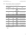
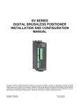
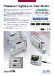
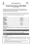
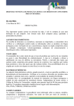
1
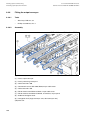
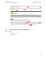
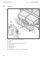
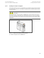
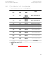
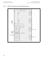
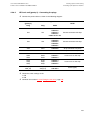
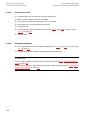
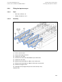
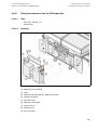
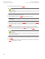
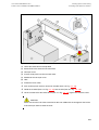
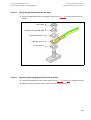
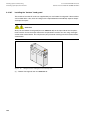
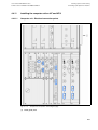
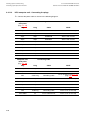
User manual SIPLACE HF series
Software Version SR.50x.xx 01/2006 US Edition
4 Setting up and commissioning
4.4 Setting up the placement machine
4.4.5
Fitting the extension kits to the machine frame
4.4.5.1
Fitting the extension kit on the PCB output side
When the placement machine is delivered, the extension kit on the PCB output side and the PCB
output conveyor are dismantled. The procedure for attaching the extension kit to the PCB output
side is as follows:
4.4.5.2
–
Fitting the output conveyor
see Section 4.4.6, page 186
–
Fitting the extension kit on the PCB output side
see Section 4.4.7, page 187
–
Installing the axis unit on the HF and HF/3
see Section 4.4.8, page 194
–
Fitting the main fault indicator
see Section 4.4.13, page 214
–
Integrating the placement machine into the line
see Section 4.4.14, page 216
–
Making final adjustments to the placement machine
see Section 4.4.15, page 219
Fitting the extension kit on the PCB input side
If the extension kit on the PCB input side was also removed for ease of transportation, you will
have to carry out the following steps before integrating the placement machine into the line (see
Section 4.4.14, page 216):
–
Fitting the input conveyor
see Section 4.4.9, page 199
–
Fitting the extension kit on the PCB input side
see Section 4.4.10, page 201
–
Installing the computer unit on HF and HF/3
see Section 4.4.11, page 207
–
Installing the axis unit on the HF and HF/3
see Section 4.4.8, page 194
–
Fitting the main fault indicator
see Section 4.4.13, page 214
–
Integrating the placement machine into the line
see Section 4.4.14, page 216
–
Making final adjustments to the placement machine
see Section 4.4.15, page 219
185
4 Setting up and commissioning
4.4 Setting up the placement machine
4.4.6
Fitting the output conveyor
4.4.6.1
Tools
4.4.6.2
–
Allen keys, DIN 911, set
–
Phillips screwdriver, size 1
User manual SIPLACE HF series
Software Version SR.50x.xx 01/2006 US Edition
Assembly
4
Fig. 4.4 - 7
Output conveyor - dual conveyor
(1) Panel, output conveyor
(2) Panel, processing conveyor 2
(3) Cable cover 20 x 200
(4) Countersunk screw, ISO 7046, M3x6, 2x per cable cover
(5) Cable cover 20 x 310
(6) Fillister head screw DIN 912, M3x5, 1x per cable cover
(7) Fillister head screw DIN 912, M6x16, and washer, 4x per panel
(8) Guide for hexagonal shaft
(9) Hexagonal shaft (single conveyor: one, dual conveyor: two)
(10) Drive unit
186
User manual SIPLACE HF series
Software Version SR.50x.xx 01/2006 US Edition
4 Setting up and commissioning
4.4 Setting up the placement machine
Æ Remove the cable covers (items 3 and 5 in Fig. 4.4 - 7) from the panels (item 1 in Fig. 4.4 7) of the output conveyor.
Æ Carefully place the panel (item 1 in Fig. 4.4 - 7) against the panel on the processing conveyor
(item 2 in Fig. 4.4 - 7).
CAUTION
4
Be careful not to cut through any of the light barrier or drive motor cables.
Æ Fix each panel using 4 fillister head screws M6x16 and the associated washers (item 7 in Fig.
4.4 - 7).
Æ Connect the power cable to the light barriers and drive motors.
Æ Fix the cable covers in place (item 3 and 5 in Fig. 4.4 - 7).
Æ Introduce the hexagonal shaft (item 9 in Fig. 4.4 - 7) into the drive unit (item 10 in Fig. 4.4 - 7).
Æ Make sure that the hexagonal shaft guide (item 8 in Fig. 4.4 - 7) always points towards the
conveyor side wall to which the drive unit (item 10 in Fig. 4.4 - 7) is fixed.
4.4.7
Fitting the extension kit on the PCB output side
4.4.7.1
Tools
–
Allen keys, DIN 911, set
–
Machine key
187
4 Setting up and commissioning
4.4 Setting up the placement machine
4.4.7.2
User manual SIPLACE HF series
Software Version SR.50x.xx 01/2006 US Edition
Assembly
4
Fig. 4.4 - 8
Fitting the extension kit on the PCB output side
(1) Extension kit
(2) Doors
(3) Fillister head screw DIN 912, M6x16 and washer
(4) Ground connection
(5) Conveyor cover
(6) Side plate, dismantled
(7) Drawer unit rail
(8) Axis unit gantries 1 and 3 (HF) or axis unit gantry 3 (HF/3)
188
User manual SIPLACE HF series
Software Version SR.50x.xx 01/2006 US Edition
4 Setting up and commissioning
4.4 Setting up the placement machine
Æ Remove both side plates (item 6 in Fig. 4.4 - 8).
CAUTION
4
Do not unscrew the three bottom screws straight away. Simply loosen them so that the side
plate does not fall off.
Æ Detach the ground cable from the side plate.
Æ Remove both doors (item 2 in Fig. 4.4 - 8) from the extension kit (item 1).
PLEASE NOTE:
4
To avoid damage, we recommend that a second person helps to assemble the extension kit.
Æ Set down the axis unit (item 8 in Fig. 4.4 - 8) at the side of the machine in order to make
enough space to fit the extension kit (item 1 in Fig. 4.4 - 8).
Æ Make sure that the connecting cables to the axis unit are not too tight.
Æ Lift one half of the extension kit (item 1 in Fig. 4.4 - 8) against the machine frame and position
it so that the assembly bracket lies on the assembly bar (item 7 in Fig. 4.4 - 8).
CAUTION
4
Make sure that this half of the extension kit does not collide with the hexagonal shaft of the
PCB conveyor and thus bend the shaft.
Æ Fix this half of the extension kit using 2 fillister head screws M6x16 and washers (item 3 in
Fig. 4.4 - 8).
Æ Before assembling the second half of the extension kit, fit the conveyor cover (item 5 in Fig.
4.4 - 8). The procedure is as follows:
189
4 Setting up and commissioning
4.4 Setting up the placement machine
User manual SIPLACE HF series
Software Version SR.50x.xx 01/2006 US Edition
4
Fig. 4.4 - 9
Fitting the conveyor cover and the second half of the extension kit
(1) Half of the extension kit already fitted
(2) Second half of the extension kit to be fitted
(3) Conveyor cover
(4) Insert 3 white plastic washers on both sides
(5) Mandrel of the conveyor cover
(6) Hole
(7) Protective cover switch
4
Æ Push 3 white plastic washers onto each mandrel (item 5 in Fig. 4.4 - 9).
Æ Guide the mandrel (item 5 in Fig. 4.4 - 9) into the hole (item 6 in Fig. 4.4 - 9).
Æ Lift the second half of the extension kit (item 2 in Fig. 4.4 - 9) against the machine frame.
CAUTION
4
Make sure that this half of the extension kit does not collide with the hexagonal shaft of the
PCB conveyor and thus bend the shaft.
190
User manual SIPLACE HF series
Software Version SR.50x.xx 01/2006 US Edition
4 Setting up and commissioning
4.4 Setting up the placement machine
Æ Introduce the mandrel (item 5 in Fig. 4.4 - 9) of the conveyor cover into the hole (item 6 in Fig.
4.4 - 9) in the second half of the extension kit.
Æ Position the second half of the extension kit so that the assembly bracket lies on the assembly
bar (item 7 in Fig. 4.4 - 8).
Æ Fix the second half of the machine using 2 fillister head screws M6x16 and washers (item 3
in Fig. 4.4 - 8).
4.4.7.3
Fixing the hexagonal shaft guide
Æ On the single conveyor, fix one guide for the hexagonal shaft (item 8 in Fig. 4.4 - 7) to the
extension kit using two fillister head screws M6x16 and washers.
Æ On the double conveyor, fix two guides for the hexagonal shaft (item 8 in Fig. 4.4 - 7) to the
extension kit using two fillister head screws M6x16 and washers.
4
4.4.7.4
Connecting the power cables - Extension kit on the PCB output side
4
Left-hand side of the extension kit
(viewed in the direction of travel)
Connector/cable
To connector/cable
Emergency stop button
Start/Stop button
X63/03020687
X63/03002526
Protective cover switch, location 3
X53/03020409
X53/03002528
Button for the component trolley docking unit,
location 3
X232/03021056
X232/03021053
4
Right-hand side of the extension kit
(viewed in the direction of travel)
Connector/cable
To connector/cable
Start/Stop button
Switch, PCB conveyor cover
X62/03020410
X62/03002525
Protective cover switch, location 2
X52/03006476
X52/03002527
Button for the component trolley docking unit,
location 2
X222/03021056
X222/03021052
4
4
4
191
4 Setting up and commissioning
4.4 Setting up the placement machine
4.4.7.5
User manual SIPLACE HF series
Software Version SR.50x.xx 01/2006 US Edition
Fitting the grounding cable for the doors
Æ Fix the two grounding cables for the doors (item 4 in Fig. 4.4 - 8) to the machine frame as
follows:
4
Hex nut M5
Spring washer M5, DIN 7980
Washer M5, DIN 125
Cable lug, annular
Contact washer
Fig. 4.4 - 10
Fitting the grounding cable
4
4
4
4
4
4.4.7.6
Checking and setting the protective cover switch
Æ Check that the protective cover switch (item 7 in Fig. 4.4 - 9, page 190) is working correctly.
Æ Adjust the protective cover switch if necessary (see Service Manual).
192
User manual SIPLACE HF series
Software Version SR.50x.xx 01/2006 US Edition
4.4.7.7
4 Setting up and commissioning
4.4 Setting up the placement machine
Installing the "bottom" hand guard
The machines from the HF series are supplied with just one "bottom" hand guard. If the machines
are installed within a line, then no hand guard is required between immediately adjacent output
and input conveyors.
WARNING
Always fit the "bottom" hand guard (item no. 03003432-01) on the input side of the first placement machine and on the output side of the last placement machine of a line using 4 hexagon
socket head screws M4x12. This will prevent your personnel reaching into the machine without
authorization.
4
Fig. 4.4 - 11
Fitting the "bottom" hand guard on the PCB output side
(1) "Bottom" hand guard, item no. 03003432-01
193
4 Setting up and commissioning
4.4 Setting up the placement machine
User manual SIPLACE HF series
Software Version SR.50x.xx 01/2006 US Edition
4.4.8
Installing the axis unit on the HF and HF/3
4.4.8.1
HF axis unit (gantries 1 and 3) - Electrical connection points
4
Fig. 4.4 - 12
194
HF axis unit (gantries 1 and 3) - Rear panel - Electrical connection points
User manual SIPLACE HF series
Software Version SR.50x.xx 01/2006 US Edition
4.4.8.2
4 Setting up and commissioning
4.4 Setting up the placement machine
HF axis unit (gantries 1 and 3) - Connecting the plugs
Æ Connect the power cable as shown in the following diagram:
4
HF axis unit
Connecting cable
NOTE
Plug
Cable
X21
03009782
03009783
03009784
03009785
03009786 W1-W5
Secure connector with clips
X22
X22
03009802
03009803
03009804
03009805
03009807
Secure connector with clips
X4tr
X4tr
03009780
Snap connector into place
X4tt
X4tt
03009781
Snap connector into place
X4ur
X4ur
03009800
Snap connector into place
X4ut
X4ut
03009801
Snap connector into place
X1to
X3to
X5to
X1to
X3to
X5to
03009791
03009792
03009793
Insert as far as the stop
X1tp
X3tp
X5tp
X1tp
X3tp
X5tp
03009794
03009795
03009796
Insert as far as the stop
X1uo
X3uo
X5uo
X1uo
X3uo
X5uo
03009811
03009812
03009813
Insert as far as the stop
X1up
X3up
X5up
X1up
X3up
X5up
03009814
03009815
03009816
Insert as far as the stop
X30_1sq
X30_2sq
X30_1sq
X30_2sq
03010054
03010054
Screw tightly
Plug
X21
4
Æ Check the switch settings for S1
1: OFF
2: ON
Æ Continue from section 4.4.8.5 "Fitting the axis unit", page 198.
195
4 Setting up and commissioning
4.4 Setting up the placement machine
4.4.8.3
User manual SIPLACE HF series
Software Version SR.50x.xx 01/2006 US Edition
HF/3 axis unit (gantry 3) - Electrical connection points
4
Fig. 4.4 - 13
196
HF/3 axis unit (gantry 3), back panel - Electrical connection points
User manual SIPLACE HF series
Software Version SR.50x.xx 01/2006 US Edition
4.4.8.4
4 Setting up and commissioning
4.4 Setting up the placement machine
HF/3 axis unit (gantry 3) - Connecting the plugs
Æ Connect the power cable as shown in the following diagram:
4
HF/3 axis unit
(gantry 3)
Plug
Connecting cable
NOTE
Plug
Cable
X21
03009782
03009783
03009784
03009785
03009786 W1-W5
Secure connector with clips
X22
X22
03009802
03009803
03009804
03009805
03009807
Secure connector with clips
X4ur
X4ur
03009800
Snap connector into place
X4ut
X4ut
03009801
Snap connector into place
X1uo
X3uo
X5uo
X1uo
X3uo
X5uo
03009811
03009812
03009813
Insert as far as the stop
X1up
X3up
X5up
X1up
X3up
X5up
03009814
03009815
03009816
Insert as far as the stop
X30_1sq
X30_2sq
X30_1sq
X30_2sq
03010054
03010054
Screw tightly
X21
4
4
Æ Check the switch settings for S1
1: ON
2: ON
Æ Continue from section 4.4.8.5 "Fitting the axis unit", page 198.
197
4 Setting up and commissioning
4.4 Setting up the placement machine
4.4.8.5
User manual SIPLACE HF series
Software Version SR.50x.xx 01/2006 US Edition
Fitting the axis unit
Æ
Æ
Æ
Æ
Æ
Æ
Carefully lift the axis unit onto the rail in the extension kit.
Make sure that you do not squash any cables.
Push the axis unit into the extension kit as far as the stop.
Secure the axis unit with the fillister head screw.
Insert the cover.
Fix the grounding cable to the doors (item 2 in Fig. 4.4 - 8, page 188), as shown in Fig.
4.4 - 10 on page 192.
Æ Lock the doors.
4.4.8.6
Fitting the side plates
Æ Fix the grounding cable to each side plate (item 6 in Fig. 4.4 - 8, page 188), as shown in Fig.
4.4 - 10 page 192.
Æ Fix the side plate to the machine frame with 6 fillister head screws.
PLEASE NOTE
If you have dismantled the output conveyor, continue from section 4.4.9 " Fitting the input conveyor" on page 199.
Once the input conveyor is fitted, then continue the assembly work from section 4.4.13 "Fitting
the main fault indicator" on page 214.
198
User manual SIPLACE HF series
Software Version SR.50x.xx 01/2006 US Edition
4.4.9
Fitting the input conveyor
4.4.9.1
Tools
4.4.9.2
–
Allen keys, DIN 911, set
–
Phillips screwdriver, size 1
4 Setting up and commissioning
4.4 Setting up the placement machine
Assembly
4
Fig. 4.4 - 14
Input conveyor - dual conveyor
(1) Panel, input conveyor
(2) Panel, processing conveyor 1
(3) Cable cover 20 x 200
(4) Countersunk screw, ISO 7046, M3x6, 2x per cable cover
(5) Cable cover 20 x 310
(6) Fillister head screw DIN 912, M3x5, 1x per cable cover
(7) Fillister head screw DIN 912, M6x16, and washer, 4x per panel
(8) Guide for hexagonal shaft
(9) Hexagonal shaft (single conveyor: one, dual conveyor: two)
(10) Drive unit
199
4 Setting up and commissioning
4.4 Setting up the placement machine
User manual SIPLACE HF series
Software Version SR.50x.xx 01/2006 US Edition
Æ Remove the cable covers (items 3 and 5 in Fig. 4.4 - 14) from the input conveyor (item 1 in
Fig. 4.4 - 14).
Æ Carefully place the panel (item 1 in Fig. 4.4 - 14) against the panel on the processing conveyor
(item 2 in Fig. 4.4 - 14).
CAUTION
4
Be careful not to cut through any of the light barrier or drive motor cables.
Æ Fix each panel using 4 fillister head screws M6x16 and the associated washers (item 7 in Fig.
4.4 - 14).
Æ Connect the power cable to the light barriers and drive motors.
Æ Fix the cable covers in place (item 3 and 5 in Fig. 4.4 - 14).
Æ Introduce the hexagonal shaft (item 9 in Fig. 4.4 - 14) into the drive unit (item 10 in Fig. 4.4 14).
Æ Make sure that the hexagonal shaft guide (item 8 in Fig. 4.4 - 14) always points towards the
conveyor side wall to which the drive unit (item 10 in Fig. 4.4 - 14) is fixed.
200
User manual SIPLACE HF series
Software Version SR.50x.xx 01/2006 US Edition
4.4.10
Fitting the extension kit on the PCB input side
4.4.10.1
Tools
4.4.10.2
–
Allen keys, DIN 911, set
–
Machine key
4 Setting up and commissioning
4.4 Setting up the placement machine
Assembly
4
Fig. 4.4 - 15
Fitting the extension kit on the PCB input side
(1) Extension kit, dismantled
(2) Doors
(3) Fillister head screw DIN 912, M6x16 and washer
(4) Ground connection
(5) Conveyor cover
(6) Side plate, dismantled
(7) Drawer unit rail
(8) Computer unit
(9) Axis unit (HF/3)
201
4 Setting up and commissioning
4.4 Setting up the placement machine
User manual SIPLACE HF series
Software Version SR.50x.xx 01/2006 US Edition
Æ Remove both side plates (item 6 in Fig. 4.4 - 15).
CAUTION
4
Do not unscrew the three bottom screws straight away. Simply loosen them so that the side
plate does not fall off.
Æ Detach the ground cable from the side plate.
Æ Remove both doors (item 2 in Fig. 4.4 - 15) from the extension kit (item 1).
PLEASE NOTE:
4
To avoid damage, we recommend that a second person helps to assemble the extension kit.
Æ Set down the computer unit (item 8 in Fig. 4.4 - 15) and the axis unit (item 9 in Fig 4.4 - 15)
at the side of the machine in order to make enough space to fit the extension kit (item 1 in Fig.
4.4 - 15).
Æ Make sure that the connecting cables to the computer and axis units are not too tight.
Æ Lift one half of the extension kit (item 1 in Fig. 4.4 - 15) against the machine frame and position
it so that the assembly bracket lies on the assembly bar (item 7 in Fig. 4.4 - 15).
CAUTION
4
Make sure that the extension kit does not collide with the hexagonal shaft of the PCB conveyor and thus become bent.
Æ Fix this half of the extension kit using 2 fillister head screws M6x16 and washers (item 3 in
Fig. 4.4 - 15).
Æ Before assembling the second half of the extension kit, fit the conveyor cover (item 5 in Fig.
4.4 - 15). The procedure is as follows:
202
User manual SIPLACE HF series
Software Version SR.50x.xx 01/2006 US Edition
4 Setting up and commissioning
4.4 Setting up the placement machine
4
Fig. 4.4 - 16
Fitting the conveyor cover and the second half of the extension kit
(1) Half of the extension kit already fitted
(2) Second half of the extension kit to be fitted
(3) Conveyor cover
(4) Insert 3 white plastic washers on both sides
(5) Mandrel of the conveyor cover
(6) Hole
(7) Protective cover switch
4
Æ Push 3 white plastic washers onto each mandrel (item 5 in Fig. 4.4 - 16).
Æ Guide the mandrel (item 5 in Fig. 4.4 - 16) into the hole (item 6 in Fig. 4.4 - 16).
Æ Lift the second half of the extension kit (item 2 in Fig. 4.4 - 16) against the machine frame.
CAUTION
4
Make sure that this half of the extension kit does not collide with the hexagonal shaft of the
PCB conveyor and thus bend the shaft.
203
4 Setting up and commissioning
4.4 Setting up the placement machine
User manual SIPLACE HF series
Software Version SR.50x.xx 01/2006 US Edition
Æ Introduce the mandrel (item 5 in Fig. 4.4 - 16) of the conveyor cover into the hole (item 6 in
Fig. 4.4 - 16) in the second half of the extension kit.
Æ Position the second half of the extension kit so that the assembly bracket lies on the assembly
bar (item 7 in Fig. 4.4 - 15).
Æ Fix the second half of the machine using 2 fillister head screws M6x16 and washers (item 3
in Fig. 4.4 - 15).
4.4.10.3
Fixing the hexagonal shaft guide
Æ On the single conveyor, fix one guide for the hexagonal shaft (item 8 in Fig. 4.4 - 14) to the
extension kit using two fillister head screws M6x16 and washers.
Æ On the double conveyor, fix two guides for the hexagonal shaft (item 8 in Fig. 4.4 - 14) to the
extension kit using two fillister head screws M6x16 and washers.
4.4.10.4
Connecting the power cables - Extension kit on the PCB input side
4
Left-hand side of the extension kit
(viewed in the direction of travel)
Connector/cable
To connector/cable
Start/Stop button
Switch, PCB conveyor cover
X61/03020410
X61/03002537
Protective cover switch, location 4
X54/03020409
X54/03002540
Button for the component trolley docking unit,
location 4
X242/03021056
X242/03021054
4
204
Right-hand side of the extension kit
(viewed in the direction of travel)
Connector/cable
To connector/cable
Emergency stop button
Start/Stop button
X64/03020687
X64/03002538
Protective cover switch, location 1
X51/03020409
X51/03002539
Button for the component trolley docking unit,
location 1
X212/03021056
X212/03021051
User manual SIPLACE HF series
Software Version SR.50x.xx 01/2006 US Edition
4.4.10.5
4 Setting up and commissioning
4.4 Setting up the placement machine
Fitting the grounding cable for the doors
Æ Fix the two grounding cables for the doors (item 4 in Fig. 4.4 - 15) to the machine frame as
follows:
4
Hex nut M5
Spring washer M5, DIN 7980
Washer M5, DIN 125
Cable lug, annular
Contact washer
Fig. 4.4 - 17
Fitting the grounding cable
4
4
4
4
4
4.4.10.6
Checking and setting the protective cover switch
Æ Check that the protective cover switch (item 7 in Fig. 4.4 - 16, page 203) is working correctly.
Æ Adjust the protective cover switch if necessary (see Service Manual).
4
205
4 Setting up and commissioning
4.4 Setting up the placement machine
4.4.10.7
User manual SIPLACE HF series
Software Version SR.50x.xx 01/2006 US Edition
Installing the "bottom" hand guard
The machines from the HF series are supplied with just one "bottom" hand guard. If the machines
are installed within a line, then no hand guard is required between immediately adjacent output
and input conveyors.
WARNING
Always fit the "bottom" hand guard (item no. 03003432-01) on the input side of the first placement machine and on the output side of the last placement machine of a line using 4 hexagon
socket head screws M4x12. This will prevent your personnel reaching into the machine without
authorization.
4
Fig. 4.4 - 18
Fitting the "bottom" hand guard on the PCB input side
(1) "Bottom" hand guard, item no. 03003432-01
206
User manual SIPLACE HF series
Software Version SR.50x.xx 01/2006 US Edition
4 Setting up and commissioning
4.4 Setting up the placement machine
4.4.11
Installing the computer unit on HF and HF/3
4.4.11.1
Computer unit - Electrical connection points
Fig. 4.4 - 19
Camera 1/3
Camera 1/3
Camera 2/4
Camera 2/4
CAN bus 2
CAN bus 2
CAN bus 1
CAN bus 1
4
Computer unit, front panel - Connecting the plugs
(1) Cable guide plate
207
4 Setting up and commissioning
4.4 Setting up the placement machine
User manual SIPLACE HF series
Software Version SR.50x.xx 01/2006 US Edition
4
Fig. 4.4 - 20
Computer unit, back panel - Connecting the plugs
(1) Cable guide plate
208
User manual SIPLACE HF series
Software Version SR.50x.xx 01/2006 US Edition
4.4.11.2
4 Setting up and commissioning
4.4 Setting up the placement machine
HF computer unit - Connecting the plugs
Æ Connect the power cable as shown in the following diagram:
4
Connecting cable
Computer unit,
front panel
(Fig. 4.4 - 19)
Plug
Plug
Cable
NOTE
X5pc
X5pc
03002958 + 03002559
Insert as far as the stop
X7pc
X7pc
03002967
Secure with screws
X8pc
X8pc
03002970
Secure with screws
X6pn
X6pn
03010051
Secure with screws
X11pn
X11pn
03010059
Secure with screws
X6pt
X6pt
03002507 W1+W2
Secure with screws
X7pt
X7pt
03003438 W1+W2
Secure with screws
X6pu
X6pu
03002508 W1+W2
Secure with screws
X7pu
X7pu
03003435 W1+W2
Secure with screws
4
4
Connecting cable
Computer unit,
back panel
(Fig. 4.4 - 20)
Plug
Plug
Cable
NOTE
X15pz
X15pz
03003434
Fix with screws
X3pz
X3pz
03004063
Fix with screws
PE1
Cable ring
Grounding cable
Fix as shown in Fig. 4.4 - 17,
page 205
X27pz
X27pz
03003437 W1-W2
Insert as far as the stop
X2pz
X2pz
03002966 W1-W5
Fix with screws
X1pz
X1pz
03002969 W1-W5
Fix with screws
X62pz
X62pz
03002488
Snap into place
PE2
Cable lug
Grounding cable
Insert as far as the stop
P24 / GND
X1
Fan in extension kit
Insert as far as the stop
209
4 Setting up and commissioning
4.4 Setting up the placement machine
4.4.11.3
User manual SIPLACE HF series
Software Version SR.50x.xx 01/2006 US Edition
HF/3 computer unit - Connecting the plugs
Æ Connect the power cable as shown in the following diagram:
4
Connecting cable
Computer unit,
front panel
(Fig. 4.4 - 19)
Plug
Plug
Cable
NOTE
X5pc
X5pc
03002958 + 03002559
Insert as far as the stop
X7pc
X7pc
03002967
Secure with screws
X8pc
X8pc
03002970
Secure with screws
X6pn
X6pn
03010051
Secure with screws
X11pn
X11pn
03010059
Secure with screws
X6pt
X6pt
03010607 W1+W2
Secure with screws
X7pt
X7pt
03010608 W1+W2
Secure with screws
X6pu
X6pu
03002508 W1+W2
Secure with screws
X7pu
X7pu
03003435 W1+W2
Secure with screws
4
4
210
Connecting cable
Computer unit,
back panel
(Fig. 4.4 - 20)
Plug
Plug
Cable
NOTE
X15pz
X15pz
03003434
Fix with screws
X3pz
X3pz
03004063
Fix with screws
PE1
Cable ring
Grounding cable
Fix as shown in Fig. 4.4 - 17,
page 205
X27pz
X27pz
03003437 W1-W2
Insert as far as the stop
X2pz
X2pz
03002966 W1-W5
Fix with screws
X1pz
X1pz
03002969 W1-W5
Fix with screws
X62pz
X62pz
03002488
Snap into place
PE2
Cable lug
Grounding cable
Insert as far as the stop
P24 / GND
X1
Fan in extension kit
Insert as far as the stop
User manual SIPLACE HF series
Software Version SR.50x.xx 01/2006 US Edition
4.4.11.4
4 Setting up and commissioning
4.4 Setting up the placement machine
Fitting the computer unit
Æ Plug in the plug-in connectors on the back panel of the computer unit (see section 4.4.11.2,
4.4.11.3).
Æ Carefully lift the computer unit onto the rail in the extension kit.
Æ Make sure that you do not squash any cables.
Æ Check that the cables for the front panel are in the lateral cable routing plate
(item 1 in Fig. 4.4 - 19, page 207).
Æ
Æ
Æ
Æ
Fix the cables to the front panel with cable ties.
Push the computer unit into the extension kit as far as the stop.
Connect the fan cable to the computer unit cable.
Plug in the plug-in connectors on the front panel of the computer unit (see section 4.4.11.2,
4.4.11.3).
Æ Secure the computer unit with the fillister head screw.
Æ Fix the grounding cable to the doors (item 2 in Fig. 4.4 - 15, page 201), as shown in Fig.
4.4 - 17 on page 205.
Æ Lock the doors.
PLEASE NOTE
On HF placement machines, continue from section 4.4.11.5 "Fitting the side plates".
On HF/3 placement machines, continue from section 4.4.12 "Installing the axis unit on the HF/3
(gantry 1 and gantry 4)" on page 212.
4.4.11.5
Fitting the side plates
Æ Fix the grounding cable to each side plate (item 5 in Fig. 4.4 - 15), as shown in Fig. 4.4 - 17
page 205.
Æ Fix the side plate to the machine frame with 6 fillister head screws.
Æ Continue from section 4.4.13 "Fitting the main fault indicator", page 214.
211
4 Setting up and commissioning
4.4 Setting up the placement machine
User manual SIPLACE HF series
Software Version SR.50x.xx 01/2006 US Edition
4.4.12
Installing the axis unit on the HF/3 (gantry 1 and gantry 4)
4.4.12.1
HF/3 axis unit (gantry 1 and gantry 4) - Electrical connection points
4
Fig. 4.4 - 21
212
HF/3 axis unit (gantry 1 and gantry 4), rear panel - Connecting the plugs
User manual SIPLACE HF series
Software Version SR.50x.xx 01/2006 US Edition
4.4.12.2
4 Setting up and commissioning
4.4 Setting up the placement machine
HF/3 axis unit (gantry 1 and gantry 4) - Connecting the plugs
Æ Connect the power cable as shown in the following diagram:
4
Axis unit
Gantry 1 and gantry 4
Plug
Connecting cable
NOTE
Plug
Cable
X31
03009762
03009763
03009764
03009765
03009766 W1-W5
Secure connector with clips
X32
X32
03009822
03009823
03009824
03009825
03009827
Secure connector with clips
X4sr
X4sr
03009760
Snap connector into place
X4st
X4st
03009761
Snap connector into place
X4vr
X4vr
03009820
Snap connector into place
X4vt
X4vt
03009821
Snap connector into place
X1so
X3so
X5so
X1so
X3so
X5so
03009771
03009772
03009773
Insert as far as the stop
X1sp
X3sp
X5sp
X1sp
X3sp
X5sp
03009774
03009775
03009776
Insert as far as the stop
X1vo
X3vo
X5vo
X1vo
X3vo
X5vo
03009831
03009832
03009833
Insert as far as the stop
X1vp
X3vp
X5vp
X1vp
X3vp
X5vp
03009834
03009835
03009836
Insert as far as the stop
X30_1tq
X30_2tq
X30_1tq
X30_2tq
03010051
03010051
Screw tightly
X31
4
4
Æ Check the switch settings for S1
1: OFF
2: OFF
213
4 Setting up and commissioning
4.4 Setting up the placement machine
4.4.12.3
User manual SIPLACE HF series
Software Version SR.50x.xx 01/2006 US Edition
Fitting the HF/3 axis unit (gantry 1 and gantry 4)
Æ
Æ
Æ
Æ
Æ
Æ
Carefully lift the axis unit onto the rail in the extension kit.
Make sure that you do not squash any cables.
Push the axis unit into the extension kit as far as the stop.
Connect the fan cable to the axis unit cable.
Secure the axis unit with the fillister head screw.
Insert the cover.
Æ Fix the grounding cable to the doors (item 2 in Fig. 4.4 - 15, page 201), as shown in Fig.
4.4 - 17 on page 205.
Æ Lock the doors.
4.4.12.4
Fitting the side plates
Æ Fix the grounding cable to each side plate (item 6 in Fig. 4.4 - 15, page 201), as shown in Fig.
4.4 - 17 page 205.
Æ Fix the side plate to the machine frame with 6 fillister head screws.
4
4.4.13
Fitting the main fault indicator
Æ Open the protective cover on location 2.
Æ Move the gantry out of the vicinity of location 2.
Æ Use the size 2.5 Allen key to loosen the four hexagon socket head screws of the long trailing
cable plate and lift out the plate.
Æ Insert the main fault indicator lamp (item 1, Fig. 4.4 - 22) into the hole (item 3, Fig. 4.4 - 22)
until the tube of the lamp projects sufficiently into the terminal beneath.
Æ Align the main fault indicator (item 1, fig. 4.4 - 22) so that the mark (item 2, fig. 4.4 - 22) points
to the right looking in the PCB direction of travel.
Æ Fix the main fault indicator in this position by tightening the two hexagon socket head screws
at the clamping point using the size 5 Allen key.
Æ Connect connector X55 on the main fault indicator (03004315-xx) to connector X55 on the
cable 03002529-xx.
Æ Fix the trailing cable plate using the four hexagon socket head screws.
214
User manual SIPLACE HF series
Software Version SR.50x.xx 01/2006 US Edition
4 Setting up and commissioning
4.4 Setting up the placement machine
4
Fig. 4.4 - 22
Fitting the main fault indicator
(1) Main fault indicator
(2) Mark
(3) Hole for the main fault indicator
(T) PCB direction of travel
215