1
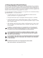
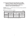
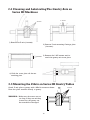
Techno Inc. Machine Maintenance Techno Inc. 2101 Jericho Turnpike New Hyde Park, NY 11042-5416 Phone: (516) 328-3970 Fax: (516) 358-2576 http://www.technocnc.com JANUARY 2006 HTM0320601 Terms and Conditions for Limited Warranty and Repairs Warranty All Techno mechanical components are warranted against manufacturer’s defects in material and workmanship for a period of one (1) year from the time of shipment from Techno facilities. All Techno electrical components are similarly warranted for a period of one (1) year from the time of shipment from Techno facilities. Techno’s sole obligation under this warranty is limited to repairing the product or, at its option, replacing the product without additional charge, provided the item is properly returned to Techno for repair as described below. The provisions of this warranty shall not apply to any product that has been subjected to tampering, abuse, improper setup or operating conditions, misuse, lack of proper maintenance, or unauthorized user adjustment. Techno makes no warranty that its products are fit for any use or purpose to which they may be put by the customer, whether or not such use or purpose has been disclosed to Techno in specifications or drawings previously or subsequently provided, and whether or not Techno’s products are specifically designed and/or manufactured for such a purpose. NOTE: Drive motors (servo or stepper) are considered “mechanical components”. THIS WARRANTY IS IN LIEU OF ALL OTHER WARRANTIES EXPRESSED OR IMPLIED. ALL OTHER WARRANTIES, INCLUDING, BUT NOT LIMITED TO, ANY WARRANTY OF MERCHANTABILITY OR FITNESS FOR A PARTICULAR PURPOSE, WHETHER EXPRESSED, IMPLIED, OR ARISING BY OPERATION OF LAW, TRADE USAGE, OR COURSE OF DEALING, ARE HEREBY DISCLAIMED. THERE ARE NO WARRANTIES THAT EXTEND BEYOND THE DESCRIPTION ON THE FACE HEREOF. Limitation of Remedy In no event shall Techno be liable for any incidental, consequential, or special damages of any kind or nature whatsoever. Techno is in no way liable for any lost profits arising from or connected to this agreement or items sold under this agreement, whether alleged to arise from breach of contract, expressed or implied warranty, or in tort, including, without limitation, negligence, failure to warn, or strict liability. Return Procedure Before returning any equipment in or out of warranty, the customer must first obtain a return authorization number and packing instructions from Techno. No claim will be allowed nor credit given for products returned without such authorization. Proper packaging and insurance for transportation is solely the customer’s responsibility. After approval from Techno, the product should be returned with a statement of the problem and transportation prepaid. If, upon examination, warranted defects exist, the product will be repaired or replaced at no charge, and shipped prepaid back to the customer. Return shipment will be by common carrier (i.e., UPS). If rapid delivery is requested by customer, then such transport is at the customer’s expense. If an out-of-warranty situation exists, the customer will be notified of the repair costs immediately. At such time, the customer must issue a purchase order to cover the cost of the repair or authorize the product to be shipped back as is, at the customer’s expense. In any case, a restocking charge of 20% will be charged on all items returned to stock. Field Service Repairs are ordinarily done at Techno’s New Hyde Park, New York facility, where all necessary instrumentation is available. This instrumentation is difficult to transport, so field service is severely limited, and will only be supplied at Techno’s discretion. If field service is required and is performed at Techno’s sole discretion, all relevant expenses, including transportation, travel time, subsistence costs, and the prevailing cost per hour (eight hour minimum) are the responsibility of the customer. Unforeseen Circumstances Techno is not liable for delay or failure to perform any obligations hereunder by reason of circumstances beyond its reasonable control. These circumstances include, but are not limited to, accidents, acts of God, strikes or labor disputes, laws, rules, or regulations of any government or government agency, fires, floods, delays or failures in delivery of carriers or suppliers, shortages of materials, and any other event beyond Techno’s control. Entire Agreement/Governing Law The terms and conditions contained herein shall constitute the entire agreement concerning the terms and conditions for the limited warranty described hereunder. No oral or other representations are in effect. This Agreement shall be governed in all respects by the laws of New York State. No legal action may be taken by any party more than one (1) year after the date of purchase. TECHNO RESERVES THE RIGHT TO CHANGE DESIGNS, SPECIFICATIONS, PRICES, AND ANY APPLICABLE DOCUMENTATION WITHOUT PRIOR NOTICE. i Table of Contents Conventions Used in this Manual ............................................................................3 About the Maintenance Manual ..............................................................................3 1. Working With Extrusion Work Surfaces .............................................................4 1.1 Using Fasteners ....................................................................................4 1.2 Preparing Scavenger Surfaces .............................................................5 2. Lubrication ....................................................................................................6 2.1 Lubrication Schedule of Double Rails ....................................................6 2.2 Lubrication Schedule of Ball Screws ......................................................6 2.3 Recommended Lubricants ....................................................................7 2.3.1 General Lubrication Specs for LC and RG ................................8 2.3.2 General Lubrication for other Machines ...................................9 2.4 Cleaning and Lubricating The Gantry Axis on Series III Machines .......10 2.5 Mounting the Z Axis on Series III Gantry Table ...................................10 3. Slides and Machines with Stepper Motors ........................................................11 3.1 Techno Stepper Motor, Limit Switch Wiring for Circular Connector ....11 3.2 DB 9 Connector Motor and Limit Switch Wiring ...................................12 3.3 Techno Rotary Table 1and 5 Motor and Limit Switch Wiring ...............12 3.4 Wiring of Techno 8 Lead Stepper Motors ...........................................13 4. Slides and Machines With Servo Motors ...........................................................14 4.1 Servo Encoder Cable Connector Pinout ...............................................14 4.2 Servo Power Cable Connector Pinouts.................................................15 4.3 Exploded View of Servo Motor ............................................................16 5. Troubleshooting ...............................................................................................17 5.1 One Axis Does Not Home .....................................................................17 5.2 Slide Does Not Move to Home Position .................................................18 5.3 Motor Stalls During Travel ...................................................................19 5.3.1 Checking the Stepper Motor ...................................................19 5.3.2 Checking the Ball Screw ..........................................................20 5.4 Slide Does Not Move Although Motor Spins Freely .............................21 5.5 How to Remove the Motor Assembly from a Techno Series III Slide .....22 5.6 Exploded View of Stepper Motor ........................................................23 ii Conventions Used in this Manual The following conventions are used throughout this manual: Bold type is used to highlight important information within the text. ) , Indicates a note containing important information related to the text. Indicates a caution or warning message that there is a possibility of damage to the equipment if certain guidelines are not observed. About the Maintenance Manual The purpose of this manual is threefold: 1. Preventive maintenance 2. Wiring and structural mapping 3. Troubleshooting The first two sections provide some guidelines for using extrusion work surfaces and for the lubrication of various parts of the machine. No maintenance is required other than routine cleaning and lubrication. The third and fourth sections give pinout, wiring, and structural diagrams of the various main components of the machine. The last section explains how to resolve operational difficulties, should they arise. If you experience mechanical or electrical problems with your machine, turn to the appropriate section and follow the instructions to identify and isolate the problem. If a problem persists, call Techno at (516) 328-3970 to receive additional assistance. , ) UNDER NO CIRCUMSTANCES SHOULD EQUIPMENT BE ADJUSTED OR DISASSEMBLED WITHOUT FIRST CONSULTING A TECHNO REPRESENTATIVE. Return of any machine or part must be authorized. A Techno representative must be contacted for a return authorization number and shipping instructions. TECHNO ASSUMES NO RESPONSIBILITY FOR ANY EQUIPMENT SENT BACK WITHOUT A RETURN AUTHORIZATION NUMBER. ) For Additional Documentation, see accompanying CD or visit our website: http://www.technocnc.com/support/index.htm 3 1. Working With Extrusion Work Surfaces , EXTRUSION WORK SURFACES COULD BE DAMAGED BY INAPPROPRIATE USE OF HARDWARE OR UNSUITABLE CLAMPING METHODS. 1.1 Using Fasteners Techno offers a broad range of compatible hardware for use with the structural extrusions, enclosure profiles, and T-slot work surfaces of all of our machines. Certain precautions should be taken when using fasteners. When using a captive square nut, double nut, or nut-strip, care must be taken to select the correct length screw to prevent bottoming on the lower surface of the Tslot. Spacer washers may be necessary to take up extra length. The T-slot lip must be covered by the clamped surface to prevent the nut from pulling out and damaging the lip. The following diagram illustrates the correct way to use fasteners. Fastener Incorrect Correct Screw bottoms on lower surface of T- slot. Correct length screw, spacer washers may be necessary. washer Screw with captive square nut T-slot lip is unrestrained, nut can pul up, damaging upper surface. T-slot lip covered by the clamped surface to prevent the nut from pulling out. . Correct length screw, spacer washers may be necessary. washer Nut with captive bolt T-slot lip is unrestrained, bolt head may pull up, damaging upper surface. 4 T-slot lip covered by the clamped surface to prevent the nut from pulling out. 1.2 Preparing Spoil Board Surfaces The surface of the Techno gantry table consists of aluminum extrusions that are produced as flat as possible. The Techno gantry machines have machined surfaces, making them flat to within .010"/ft. Ultimately, the flatness of the machining surface depends additionally on the surface the machine is installed on, the degree of levelling that has been applied to the machine, and the load which is being applied to the surface. If a very high degree of flatness is required for your application, we recommend attaching a spoil board surface to the extrusion surface: You should prepare the spoil board surface only after the machine has been installed and levelled at its permanent location. The spoil board surface may be of plexiglass, fiberboard, plywood, or aluminum. A spoil board surface may be attached using screws or clamps. If you fasten the spoil board surface using screws, follow the guidelines provided on page 4 to make sure it is done correctly. After attaching a spoil board surface, perform a levelling pass over it using a router and a flat endmill. The resulting surface will be "dead flat" with respect to the tool on the machine. ) In addition to creating flat surfaces, we recommend the use of secondary spoil board surfaces for general machining applications in order to prevent damage to the machine from accidents during prototyping and testing operations. , DO NOT MACHINE THE EXISTING ALUMINUM EXTRUSION SURFACE . THIS WILL WEAKEN THE INTEGRITY OF THE MACHINE AND MAKE THE SURFACE TOO THIN TO BE FUNCTIONAL. , ) DO NOT REMOVE THE EXTRUSIONS ON THE WORK SURFACE FOR ADJUSTMENT OR ALIGNMENT. THIS WILL COMPROMISE THE INTEGRITY AND ALIGNMENT OF THE MACHINE. For Additional Documentation see accompanying CD or visit our website: http://www.technocnc.com/support/index.htm 5 2. Lubrication The drive components on all Techno machines are shipped from our factory with greased ball screws and a protective oil coating on the rails. The grease is compatible with DIN 51825, and the oil is compatible with DIN 51517T3. (The DIN standards are generally accepted for various industrial products.) 2.1 Lubrication Schedule of Double Rails The steel shafts in the double rails and the linear bearings should be lubricated and protected on a regular basis according to the operating conditions, as follows: ) If you are using the system in a very dusty environment (e.g., woodworking), you should clean and lubricate the rails after every 8-10 hours. This frequent cleaning and lubrication is necessary because the dust particles tend to settle on the machine and absorb the oil, causing the machine to run dry. A dust collection system should always be used in dusty environments. If you are using the system in a relatively clean, dust-free environment, you should clean and lubricate the rails after every 100-150 hours. Wipe the rails clean before lubricating. Lubricate the rails with an oil that contains both a lubricant and a rust inhibitor, 2.2 Lubrication Schedule of Ball Screws Lubricate the ball screws after the first 50 hours of service. Subsequently, you should lubricate the ball screws according to the operating conditions, as follows: In very dusty environments, clean and lubricate the ball screws after every 20-40 hours of service. In relatively clean environments, lubricate the ball screws after every 300-700 hours. Wipe any grease and dust off of each screw before lubricating. Either an oil or grease type lubricant is suitable for the ball screw mechanism (see page 7). 6 2.3 Recommended Lubricants The type of lubricant you should use on your machine depends upon the screw pitch and the speeds at which you usually run the machine. The table below is provided as a guide. Screw Pitch 2mm 4mm 5mm Linear Speed at 1500 RPM 120 in./min. 240 in./min. 300 in./mm We recommend grease for the ball screws on machines run at average RPM's (less than 1500), because grease provides a tighter system, is less likely to result in a system running dry, and is independent of the mounting position of the machine. If you are running your machine at linear speeds less than those in the second column, you should use grease as a lubricant. We recommend an oil lubricant for the ball screws on machines run at very high RPM's (approximately 1500). If you are running your machine at speeds approximating those in the second column, you should use an oil lubricant. Techno can supply the following lubricating package from stock: Part Number H90Z00-LUBEKIT2 Description Unit Protective coating and lubricating grease 16 oz. can 8 oz. tube We recommend a lubricating grease such as ALVANIA-1, ALVANIA-2, or ALVANIA-3, for light, medium, and heavy duty applications respectively. These products are available from Shell Oil Co., but a comparable lubricating grease is acceptable. DO NOT USE SILICONE AS A LUBRICANT. DOING SO MAY CAUSE DAMAGE TO THE MACHINE. , ) For Additional Documentation, see accompanying CD or visit our website: http://www.technocnc.com/support/index.htm 7 2.3.1 General Lubrication Specifications for LC and RG Series Machines AVAILABLE ACCESSORIES PART NO.: H90Z00LUBEKIT3 PART NO.: HL5600M931170 TECHNO LUBE KIT TECHNO GREASE GUN PRICE: $75.00 PRICE: $30.00 Y-Axis – THK Products Grease: Lithium-based grease (JIS NO. 2) or Urea-based Grease (JIS No. 2), such as AFB Grease (THK), Alvania Grease No. 2 (Shell), Daphne Eponex Grease No. 2 (Idemitsu Kosan) or equivalent. Oil: Sliding surface oil or turbine oil (ISOVG32-68), such as Super Multi 32 to 68 (Idemitsu Kosan), Vactra No. 2S (Mobile), DT Oil (Mobile), Tonner Oil (Showa Shell or equivalent. TABLE 1 THK RAIL BALLSCREW GREASE OIL √ √ √ √ CARRIAGE √ Note: On some items you can use either the grease or oil. X and Z-Axes – ISEL Products Grease: Alvania-1, -2, -3 (Shell) for light, med. and heavy-duty apps, respectively. ISO VG 100 Specification. Oil: Renolin CLP 100 (Part No. 299020). TABLE 2 ISEL RAIL BALLSCREW GREASE CARRIAGE √ √ √ OIL Note: On some items you can use either the grease or oil. 8 √ 2.3.2 General Lubrication Specifications for CPM Machines, DaVinci, Gantry III, Standard Duty, Heavy Duty 2, Narrow Profile 2, Blueline 1, Blueline 3, ZF1 and ZF3 Machines. Grease: Alvania-1, -2, -3 (Shell) for light, med. and heavy-duty apps, respectively. ISO VG 100 Specifications. Oil: Renolin CLP 100 (Part No. 299020). TABLE 3 ISEL RAIL BALLSCREW GREASE CARRIAGE √ √ √ OIL Note: On some items you can use either the grease or oil. 9 √ 2.4 Cleaning and Lubricating The Gantry Axis on Series III Machines 4 screws 4 screws 1) Remove the Z axis (4 screws). 2) Remove Z axis mounting Carriage plate (4 screws). 3) Remove the 2 M5 screws used to attach the gantry axis cover plate. 4) Slide the cover plate off the two retaining pins. 2.5 Mounting the Z Axis on Series III Gantry Tables Attach Z axis plate to gantry with 4 M6x14 screws as shown. Note that plate attaches directly to gantry. WARNING: Make sure the screw are not too long, If they are and they bottom out, the gantry can be scratched or damaged. 10 4 screws 3. Wiring Diagrams 3.1 Techno Stepper Motor and Limit Switch Wiring, Amphenol (Circular) Connector Wiring For Series III Slide With Circular Connector (This Includes Gantry III Tables, Bridge Mount Slides, Standard Duty Slides, Heavy Duty Slide II, Narrow Profile Slide 2, Blueline1, Blueline 3, ZF3, Rotary Table 2, and Rotary Table RF,(ZF1 See DB9 Connector on page 10)In this diagram, black circles are used to indicate Amphenol connector pins. Clear circles are used to indicate holes (no pin present). The pins and their functions are as follows: Pin # Function 1 2 3 Phase Phase Phase Phase 1A 1B 2A 2B In the diagram above, these four pins are represented by the four large black circles in the center. 5 7 9 Ground for Home Switch Machine Ground Home Switch -- normally closed In the diagram above, pins 4-7 and 9 are represented by the five small black circles around the outer part of the connector. 4 6 Brake Positive Brake Negative Pins 4 and 6 are used for slides with brakes only. If a crimp tool is not available, the wires can be directly soldered to the pins and the pins can be secured to the cable jacket by crimping them with needle nose pliers. 11 3.2 Techno Stepper Motor and Limit Switch Wiring, DB 9 Connector The diagram below illustrates the positioning of the pin numbers on the connectors. The male connector (the connector with the pins) is located on the motor housing and numbered as shown. These numbers are imprinted on the plastic shell of the connector. The female connector (the connector with the sockets) is located on the Motor Cable. Its pin numbers (and functions) are the same as those on the male connector, but their positions are reversed. Limit switch (closed) Male connector (on motor housing) Common (brown) NC (white) NO (green) Wiring For ZF1 Slide (Note there is no Brake Option for ZF1 Slides.) Pin # Function Pin # Function 1 2 3 4 5 6 7 8 9 Motor Phase 1A Motor Phase 1B Motor Phase 2A Motor Phase 2B Home Switch Normally Not connected Not connected Not connected Limist switch common Closed contact 3.3 Techno Stepper Motor and Limit Switch Wiring, Rotary Table 1 and 5 The diagram below illustrates the positioning of the pin numbers on the connectors. The male connector (the connector with the pins) is located on the motor housing and numbered as shown. These numbers are imprinted on the plastic shell of the connector. The female connector (the connector with the sockets) is located on the Motor Cable. Its pin numbers (and functions) are the same as those on the male connector, but their positions are reversed. Male connector (on motor housing) Proximity switch (closed) Ground Switch Sensor Output 24 V Wiring for Rotary Table 1 and Rotary Table 5 (Note Switch is npn, normally closed.) Pin # Function Pin # Function 1 2 3 4 5 6 7 8 9 Motor Phase 1A Motor Phase 1B Motor Phase 2A Motor Phase 2B Ground Not connected Not connected 24 V Switch Sensor Output 12 3.4 Wiring of Techno 8 Lead Stepper Motors We pre-wire Techno slide motors in the bipolar parallel mode. This provides the maximum torque and speed capabilities available with the Techno series of stepper amplifiers. Other amplifiers might perform better in either the bipolar series or the unipolar modes. The diagrams on this page illustrate the various wiring configurations for Unipolar Mode stepper motors. , , IT IS EXTREMELY EASY TO CUT THE INSULATION ON EITHER A MOTOR LEAD OR LIMIT SWITCH. IN ORDER TO PREVENT THIS FROM OCCURRING, PAY SPECIAL ATTENTION TO THE LOCATION OF THE WIRES DURING THE REMOVAL OR INSTALLATION OF A MOTOR COVER. THE MOTOR OR THE ELECTRONIC CONTROLLER WILL BE DAMAGED IF THE INSULATION ON ANY OF THE LEADS IS CUT. Bipolar Series IMPROPER WIRING CAN DAMAGE THE DRIVER. Motor Wiring Color Code A # 1 2 3 4 5 6 Color black white/black white/orange orange red white/red Bipolar Parallel Color Code B # 1 2 3 4 5 6 Color green white/green white/yellow yellow black white/black NOTE: Colors may change if there is a change in motor manufacturers. 13 4. Slides and Machines With Servo Read warning Motors below! (circular male) , (DB15 male) THE MOTOR PLATE, COUPLING, AND MOTOR ASSEMBLY MOUNTING PLATE MUST FIT TOGETHER TIGHTLY WITHOUT ANY UNDUE FORCE. IF THIS IS NOT THE CASE, DO NOT INSERT THE MOTOR MOUNT SCREWS. YOU MAY HAVE TO REPOSITION THE COUPLING IN ORDER TO GET A PROPER FIT. Servo Motor With Encoder And Motor Cable Connectors 4.1 Servo Encoder Cable Connector Pinouts (For all Gantries, Slides and Rotary Tables) The following pinouts are for the DB15 male connector. For Standard Servo Motor (X or Y axis) Pin # 1 2 3 4 5 6 7 8 9 10 11 12 13 14 15 Function E-Stop Loop A B I +5V HOME Switch (see diagram below) No connection +24V No connection A B I Encoder GND HOME Switch GND (see diagram) E-Stop Loop Encoder Type (Dynapar) 1000ppr White (Jumper to Pin 15) Red/BLK WHT/BLK Blue Red Red (From HOME Switch) NONE Brown NONE Green Orange White Black Black (from HOME Switch) White (Jumper to Pin 1) 14 For Z Axis Motor Pin # 1 2 3 4 5 6 7 8 9 10 11 12 13 14 15 Function Encoder Type (Dynapar) 1000ppr E-Stop Loop B A I +5V HOME Switch (see diagram below) No connection +24 V No connection B A I Encoder GND HOME Switch GND (see diagram) E-Stop Loop White (Jumper to Pin 15) WHT/BLK Red/BLK Blue Red Red (From HOME Switch) NONE Brown NONE Orange Green White Black Black (from HOME switch) White (Jumper to Pin 1) 4.2 Servo Power Cable Connector Pinouts (Note: For the Rotary Tables 1 and 5, pin 6 is sensor output pin 8 is +24V, pin 14 is ground) The following pinouts are for the 4 pin male circular connector. For Standard Servo Motor (X or Y axis) Pin # 1 2 Function Motor + Motor - Wire Red (from motor) Black (from motor) Function Motor + Motor Brake Brake +24V Wire Black (from motor) Red (from motor) White (from brake) White (from brake) For Z Axis Motor Pin # 1 2 3 4 15 4.3 Exploded View of the Servo Motor There should be at least a 2 mm gap between the two halves of the coupling screw set ...and the gap should be the same size all the way around the coupling! motor assembly mounting plate coupling set screw ** (first) hole coupling set screw (second) (to reach coupling set screws) coupling (end-of-travel wiring exits here) hole Exploded View of the Servo Motor motor standoff motor plate (contains end-of-travel wiring) motor motor mount screws (4) encoder screw shaft bolts (4) gantry WARNING: THE MOTOR PLATE, COUPLING, AND MOTOR ASSEMBLY MOUNTING PLATE MUST FIT TOGETHER TIGHTLY WITHOUT ANY UNDUE FORCE. IF THIS IS NOT THE CASE, DO NOT INSERT THE MOTOR MOUNT SCREWS. YOU MAY HAVE TO REPOSITION THE COUPLING IN ORDER TO GET A PROPER FIT. BUT REMEMBER TO LEAVE APPROXIMATELY A 2 MM SPACE BETWEEN THE TWO 16 5. Troubleshooting , THESE GUIDELINES ARE MEANT FOR IDENTIFYING AND ISOLATING PROBLEMS ONLY. UNDER NO CIRCUMSTANCES SHOULD EQUIPMENT BE ADJUSTED OR DISASSEMBLED WITHOUT FIRST CONTACTING A TECHNO REPRESENTATIVE. 5.1 One Axis Does Not Home If one axis does not properly move to HOME position, but the other axes do, perform the following steps to isolate the problem. ) The axis slide cannot be on the limit switch when attempting to home. If an axis does not home, check to see if it is in contact with the limit switch. If it is, manually move the table away from the switch and attempt HOME function. Your controller (Stepper or Servo) must be switched OFF to manually move this axis. 1. Turn off power to the controller. , REMOVING A CABLE WHEN POWER IS ON TO THE CONTROLLER CAN RESULT IN DAMAGE TO THE ELECTRONICS. 2. Switch the motor end of the cable on the problem axis with the motor end of the same cable of another axis that homes properly. Restore power and attempt HOME function. a) If the trouble remains on the initial axis, there is a problem with the axis machinery. Go to page 17 to check the limit switch for that axis, and if necessary, to page 18 to check the motor. b) If the trouble switches to the other axis, the problem is with the wiring or the electronics. Continue with step 3, below. 3. Turn off power. Swap the cable on the problem axis with the same cable of another axis that homes properly (switch cables completely). Restore power and attempt HOME function. a) If the trouble remains on the initial axis, the problem is with the electronics. Continue with step 4, below. b) If the trouble switches to the other axis, you have a bad cable and need to replace it. 4. Turn off power. Swap the amplifier (except for the LP Controller) for the problem axis with the amplifier of another axis that homes properly. Restore power and attempt HOME function. a) If the trouble remains on the initial axis, there may be a problem with the electronics. Call Techno. b) If the trouble switches to the other axis, the problem is with the amplifier. Call Techno. 17 5.2 Slide Does Not Move to Home Position There is a limit switch in each of the motor housings. Techno software uses this switch to establish a mechanical home position. These two switches are wired in series. You should check the axis limit switch if an axis slide does not move to the home position properly. Use an OHM meter to check the limit switch, following the procedure below. 1. Turn off the power to the controller, and remove the motor cable from the axis to be checked. , REMOVING A CABLE WITH POWER ON TO THE CONTROLLER CAN RESULT IN DAMAGE TO THE ELECTRONICS. 2. Manually move the axis slide about 6 inches away from the motor housing to ensure that theslide is not making contact with the limit switch (see diagram below). 3. Check resistance between pins 5 and 9 for Stepper Motors, and pins 6 and 14 for Servo Motors. This is a closed circuit, so you should read a very low resistance (1 or 2 ohms at most). If the resistance is higher, the limit switch may be broken. Call Techno. 6 inches pin 9 pin 5 4. To ensure that the limit switch has been contacted, manually move the slide towards the motor housing until it does not move any further (see diagram below). 5. Check resistance between pins 5 and 9 for Stepper Motors, and pins 6 and 14 for Servo Motors. This should now be an open circuit, and you should read a very high resistance. If the resistance is not high, the limit switch may be broken. Call Techno. Push to end of axis pin 9 pin 5 18 5.3 Motor Stalls During Travel If the slide stalls during travel, a problem with the motor or ball screw could be indicated. You can check both of these to see which is causing the malfunction. ) The slide may stall if you are trying to reach a speed beyond the limit of your machine. This limit depends upon the size of the amplifier, the size of the motor, your acceleration rate, the screw pitch of the machine, and the size of the load. Before checking the machinery, try running the slide at a slower speed. If the slide no longer stalls, then your original speed was too high. 5.3.1 Checking the Stepper Motor Use this close up of the motor housing as a guide when checking the motor. 1. With the power off, make sure the motor turns freely by rotating the knob manually. 2. Using an ohmmeter, test the resistance across each of the Motor Phases: Check the resistance between pins 1 and 2 on the connector (Motor Phase 1). Check the resistance between pins 3 and on the connector (Motor Phase 2). Each phase should have a resistance between 0.6-1.2 ohms. A lower resistance indicates a short. Call Techno. A much higher resistance indicates an open circuit or a broken wire. Call Techno. 3. Using an ohmmeter, check the resistance between pins 1 and 3. The resistance should be very high (at least 1M ohms), indicating an open circuit. If not, call Techno. 19 5.3.2 Checking the Ball Screw , DO NOT, UNDER ANY CIRCUMSTANCES, REMOVE THE BALL SCREW OR BALL NUT. DOING SO WILL RELEASE THE BALL BEARINGS. SINCE THE BALL BEARINGS CANNOT BE REPLACED, YOU WILL HAVE TO PURCHASE A NEW BALL SCREW/BALL NUT. To check the ball screw, follow the instructions below. 1. Turn off the power. 2. Manually move the axis from one end to the other and back by rotating the knob on the motor. For Servo Motors, you must push on the crriage plate.Check for rough spots as the axis travels along the ball screw. 3. Check for play in the nut using the diagram below as a guide: push slide back and forth slide plate lock nut (see note) place finger here a) Turn on the power so the motor has holding torque. b) Place the tip of your finger on a stationary surface and lean the ball of your finger against the slide plate as shown in the diagram. c) Push the slide plate back and forth. It should not move at all. If the plate has free play, do the following: Make sure the screws to the plate are tightened. Remove the carriage plate (see page 8) and check the radial bearings on either side of the ball nut (located at the end of the ball screw). Check to see if the ball nut has loosened. The vibrations may have caused this to occur. If so, call Techno. Check to see if the lock nut has loosened. If so, call Techno. 20 , ) DO NOT ATTEMPT TO TIGHTEN LOCK NUT. OVERTIGHTENING MAY CAUSE DAMAGE TO THE MACHINE. There is always a lock nut on the motor side of the ball screw(inside the assembly). However, many models do not have a lock nut on the opposite side, which is shown in the diagram. 5.4 Slide Does Not Move Though Motor Spins Freely If the motor spins normally, but the slide does not move, it is possible that the coupling is loose. Refer to the diagram on page 14 and perform the following steps. 1. Remove plug from the side of the motor assembly. 2. While looking through the hole, rotate knob until clamping screw is visible. 3. Tighten clamping screw in coupling using M3 Allen Key. , REMEMBER, ASIDE FROM FOLLOWING THE RECOMMENDATIONS MADE IN THIS MANUAL, NEVER ADJUST OR DISASSEMBLE EQUIPMENT WITHOUT FIRST CONSULTING A TECHNO REPRESENTATIVE. IF YOU HAVE A PROBLEM THAT CANNOT BE RECTIFIED BY FOLLOWING STEPS OUTLINED IN THIS MANUAL, CALL A TECHNO REPRESENTATIVE AT (516) 328-3970 FOR FURTHER INSTRUCTIONS. 21 5.5 How to Remove the Motor Assembly from a Techno Series III Slide (Gantry III, Bridge Mount, and Standard Duty Slides) If it becomes necessary to remove the motor assembly from a Series III Techno Slide or Gantry utilize the following exploded diagram as a guide. (7) (8) (10) (4) (5) (9) (14) (3) (1) (6) (2) (11) (13) (1) (2) (3) (4) (5) (6) (7) (8) (9) Plug Coupling Set Screw Coupling Housing 4 Screws M6x12 Motor Housing Flange Header Plate 8 Screws M6x22 Mounting Plate Rubber Sealed Carrier Plate (10) Techno Inertial Damper "Knob"(not visible) (11) Connector for Limit Switch (12) 2 Carriage Plate Screws (13) Actuating Pinhole (14) Plug for Limit Switch Connector (12) The tools required for disassembly are: M3, M4, and M5 Allen Keys A flathead screwdriver. 1) Remove Plug (1) using flathead screwdriver. 2) Looking through this opening, turn the Knob until Coupling Set Screw (2) is visible in Coupling Housing (3). For slides equipped with servo motors carefully slide the mounting plate until the Coupling Set Screw is visible. 3) Loosen, but do not remove, Coupling Set Screw (2) using M3 Allen Key. 4) Using M5 Allen Key, loosen Screws M6x12 (4) around the Motor Housing Flange (5), and carefully remove the motor assembly from the Header Plate (6). Note the presence of the Plug for the Limit Switch (14). You must carefully remove this Plug from the Connector (11) while removing the Motor Assembly. To avoid turning the Plug upside down when reconnecting, take note of the orientation of the plug. Also Note the Techno Inertial Damper "Knob"(10) is not visible above, but is visible on the next page within the Exploced View of the Stepper Motor. 22 5.6 Exploded View of the Stepper Motor ical Typ unting o r M Rea Ball Screw Spring Washers (3X) Mounted Ball Bearing Flexible Shaft Coupling Locknut KM Series Ball Nut or Series 1 Ball Nut M5x70 Socket Head Screws Mounted Ball Bearings Fr ical g Typ untin o M t n o Motor Standoff & Coupling Housing Ne ma 23 Mo tor NOTE¹: Sometimes the Stepper Motor comes with a motor cover. This is NOT shown in the exploded view above. NOTE²: If clearance holes are used for the mounting screws on the two endplates, the screw/rail system is relatively easy to align and will not require high precision machining. 23 Techno Inertial Damper "Knob"