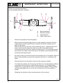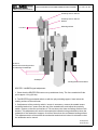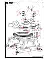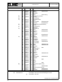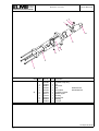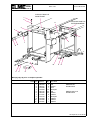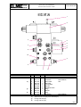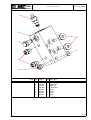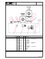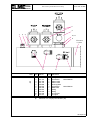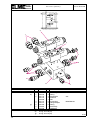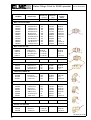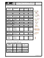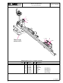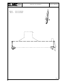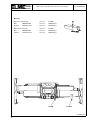
1
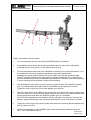
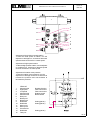
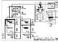
SWEDISH
SPREADER
SYSTEMS
ELMHULTS KONSTRUKTIONS AB
SERVICE AND PARTS MANUAL
MODEL
MANUAL NO
817
1-1202
www.elme.com
Head office, Manufacturing,
Sales and Service
Elmhults Konstruktions AB
Box 174
343 22 ÄLMHULT
SWEDEN
TEL: +46 476 55 800
FAX: +46 476 55 899
E-mail: [email protected]
C 2005 ELME SWEDEN
Sales and Service
ELME International BV
PO Box 417
5700 AK HELMOND
NETHERLANDS
TEL: +31 492 47 2727
FAX: +31 492 47 2728
E-mail: [email protected]
SERVICE MANUAL
Section A
User instruction
Section B
Service manual
Section C
Diagrams
PARTS MANUAL
Section D
Mechanical parts
Section E
Hydraulic parts
Section F
Electrical parts
Section G
Special parts
SWEDISH
SPREADER
SYSTEMS
ELMHULTS KONSTRUKTIONS AB
C 2004 ELME SWEDEN
SWEDISH
SPREADER
SYSTEMS
ELMHULTS KONSTRUKTIONS AB
MODEL: 817
BUILD INDEX NO. 1-1202
Service manual build index
SECTION A
USER INSTRUCTION
A100-008
Driver instruction
SECTION B
SERVICE MANUAL
B110-198
B110-017
B110-068
B110-081
B110-251
B9-134
Lubrication chart
Maintenance instruction
Servicing pensular twistlock
Extension cylinder service inst.
Twistlock indication and end beam adjustment
Description rotation block
SECTION C
DIAGRAMS
C120-001
781 815
780 686
780 685
782 917
Hydraulic symbols
Hydraulic schematic
Wiring diagram
Electric schematic
Electric device list
03-05
C 2005 ELME SWEDEN
SWEDISH
SPREADER
SYSTEMS
ELMHULTS KONSTRUKTIONS AB
MODEL: 817
BUILD INDEX NO. 1-1202
Parts manual build index
SECTION D
MECHANICAL PARTS
D10-689
D10-690
D10-779
D10-790
D50-300
Main frame
Rotator assy.
Stop assy.
Wear pads
Pendular twistlock assy.
SECTION E
HYDRAULIC PARTS
E60-340
E60-373
E60-471
E70-525
E70-784
E70-535
E70-606
E70-607
E70-582
E70-610
E70-611
Sideshift cylinder assy.
Extension cylinder assy.
Damping cylinder assy.
Swivel assy.
Valve assy. (rotation/brake)
Valve assy. (swivel)
Valve assy. (extension)
Valve assy. (extension with stops)
Valve assy. (sideshift)
Parker fittings
Hydraulic hose system
SECTION F
ELECTRICAL PARTS
F80-323
F80-264
F80-266
Sensor arr. (end beam)
Electrical parts
Indicator lights assy.
SECTION G
SPECIAL PARTS (OPTIONAL)
G90-147
G90-148
G90-152
G90-216
Additional parts (pins for damping cyl.)
Additional parts (bumper)
Additional parts (brackets for hoses and cables)
Additional parts (cover plate)
03-05
C 2005 ELME SWEDEN
SECTION
A
USER INSTRUCTION
SWEDISH
SPREADER
SYSTEMS
ELMHULTS KONSTRUKTIONS AB
C 2004 ELME SWEDEN
SWEDISH
SPREADER
SYSTEMS
USER INSTRUCTIONS
ELMHULTS KONSTRUKTIONS AB
PAGE NO A 100-008-1
ELME CONTAINER SPREADER
Model No. 817
DRIVER INSTRUCTIONS
The ELME Model 817 Container spreader is a technically advanced piece of
equipment which, if it is carefully used and maintained will serve its purpose for many
years.
Initial check.
Each work shift should be started by making a visual check of the unit ( this must be
part of the daily routine. ) Possible damage will in this way be discovered at an early
stage thus enabeling repairs to be carried out at much lower cost.
NEVER USE THE UNIT UNLESS ALL SAFETY DEVICES FUNCTION CORRECTLY
!!!
CONTAINER HANDLING
1 Starting work with the spreader.
First of all the length of the spreader must be adjusted to the size of container that is
required to be lifted. This is done by retracting the stops ( if fitted ) and then activating
the extention lever or button in order to extend or retract the spreader beams to the
desired length.
NOTE ! it is important to remember that loads should only be lifted at the
specified lengths for which the spreader is designed ie. 20ft. 30ft. 35ft.40ft and in
some cases 45ft. Where stops are fitted the stops should be used to position the
beams accuratly at one of the above mentioned positions. If the spreader is not
equipped with stops then the spreader may only be used for lifting 20 and 40ft.
containers. Lifting outside the specified positions can result in serious damage
to the spreader.
When the required length has been reached , lift the spreader high enough to give
good visibility under it. This serves two purposes, 1 it gives good visibility for travelling
and 2 it positions the spreader ready for picking up the first container. The spreader
should now be side shifted to the center position and the reach function operated to
the fully retracted position. This will be termed ”THE BASIC POSITION” in the rest of
the instruction.
2. Picking up a container.
If necessary raise the spreader in order to have plenty of space between it and the
container. Always attempt to position the spreader centrally over the container.
The final adjustments for lining up the twist locks with the corner castings of the
container can now be made.
05-02
C 2002 ELME SWEDEN
SWEDISH
SPREADER
SYSTEMS
ELMHULTS KONSTRUKTIONS AB
USER INSTRUCTIONS
PAGE NO A 100-008-2
By using the controls for shift and reach, position the spreader accurately over the corner
castings and then lower the spreader into them. If the twist locks or some of the twist locks
do not fit into the corner castings properly, CAREFULLY lift the spreader just free of the
container, readjust its position and the try again. NEVER PUSH OR SIDE SHIFT while
any of the twist locks are still engaged in the corner castings of the container. When all the
twist locks are correctly engaged in the corner castings the spreader should be lowered
until it rests unsupported on the container, this is termed as the spreader being correctly
SEATED, and this will be indicated by the SEATED LIGHT being switched on. As soon as
this happens the twist locks can be activated to the locked position and the LOCKED
LIGHT will be switched on.
CHECK THAT THE ”LOCKED” LIGHT HAS BEEN SWITCHED ON and then lift the
container to the required height for loading and / or travelling. Before moving the container,
return the spreader to the ”BASIC POSITION”. The container is now ready to be
transported to a new location. When travelling always keep the load at the lowest possible
height and drive carefully.
3. Depositing a container.
When approaching the new location for the container ( this could be a chassis or a stack
etc. ) lower the container to the required height and adjust the position of the corner
castings so that they are accuratly situated above the corner locks of the chassis. Lower
the container ensuring that its corner castings locate on the corner locks.
NEVER USE MORE TILT THAN NECESSARY AND NEVER PUSH !!!
WARNING !!! A heavy container and the weight of a spreader will do serious
damage to a trailer or chassis if not handled with care.
The twist locks may now be activated to the ”UNLOCKED” position, the spreader lifted free
of the container and the truck backed away.
4. General advice
- Always adjust the spreader back to the ”BASIC POSITION” after every handling cycle.
- When parking the truck and spreader or when they are not in use for longer periods of
time, always make a habit of lowering the spreader to its lowest position.
- Read all instruction books carefully and be sure that you understand them.
- Should there be anything you do not understand, then contact your local dealer who will
ensure that all your questions are answered.
05-02
C 2002 ELME SWEDEN
SECTION
B
SERVICE MANUAL
SWEDISH
SPREADER
SYSTEMS
ELMHULTS KONSTRUKTIONS AB
C 2004 ELME SWEDEN
SWEDISH
SPREADER
SYSTEMS
MAINTENANCE INSTRUCTIONS
PAGE NO B 110-198-1
ELMHULTS KONSTRUKTIONS AB
LUBRICATION CHART
for Model 817
4
1
2
8
6
3
4
8
5
WHERE GREASE IS RECOMMENDED USE
MULTI PURPOSE GREASE WITH 2-4 %
MOLYBDENEM DISULFIDE ADDITIVE.
5
7
1
3 2
1 Slider pads extension
2 Twist locks
3 Extension cylinder
4 Stops
5 Slider pads side shift
6 Slewing ring bearing and gear
7 Side shift cylinders.
8 Slew gear box and brake
(See individual description of each
lubrication point.)
POSITION 1
WEAR PADS FOR MAIN BEAMS AND EXTENDING BEAMS
NO. OF GREASE POINTS 24.
INTERVAL - EVERY 500 HOURS OR 3 MONTHS.
6 TRACKS ON EACH EXTENDING BEAM.
6 TRACKS ON THE INSIDE OF EACH MAIN BEAM.
A
B
( SEE ARROWS "A" AND "B" )
LUBRICANT - MULTI PURPOSE GREASE
11-03(12-02,05-02)
C 2002 ELME SWEDEN
SWEDISH
SPREADER
SYSTEMS
MAINTENANCE INSTRUCTIONS
PAGE NO B 110-198-2
ELMHULTS KONSTRUKTIONS AB
POSITION 2
END BEAMS AND TWIST LOCKS.
NO. OF GREASE POINTS 8.
INTERVAL - EVERY 500 HOURS OR 3 MONTHS.
1 GREASE NIPPLE IN EACH END BOX.
1 GREASE NIPPLE IN EACH SLEEVE
LUBRICANT - MULTI PURPOSE GREASE
C
POSITION 3
EXTENSION CYLINDER SUPPORT WEAR PADS
AND TRACKS.
INTERVAL - EVERY 1000 HOURS OR 6 MONTHS
NO. OF GREASE POINTS 4.
2 TRACKS IN EACH EXTENSION BEAM.
LUBRICANT - MULTI PURPOSE GREASE.
POSITION 4
STOP CYLINDERS.
NO. OF GREASE POINTS 2.
INTERVAL - EVERY 500 HOURS OR 3 MONTHS.
POINTS. 1 GREASE NIPPLE ON EACH STOP CYLINDER.
LUBRICANT - MULTI PURPOSE GREASE
POSITION 5
SIDE SHIFT SLIDER PADS
NO. OF GREASE POINTS 4
INTERVAL - EVERY 500 HOURS OR 3 MONTHS
1
POINTS. 2 TRACKS ON EACH SIDE OF THE SPREADER
LUBRICANT - MULTI PURPOSE GREASE.
2
11-03(12-02,05-02)
C 2002 ELME SWEDEN
SWEDISH
SPREADER
SYSTEMS
MAINTENANCE INSTRUCTIONS
PAGE NO B 110-198-3
ELMHULTS KONSTRUKTIONS AB
POSITION 6
SLEWING RING BEARING AND GEAR.
INTERVAL - EVERY 100 HOURS OR MONTHLY
NO. OF LUBRICATION POINTS 6.
4 GREASE NIPPLES POSITION "A" MOUNTED AT ONE
CENTRAL POINT ON THE UPPER ROTATOR FRAME
PLATE FOR GREASING THE BEARING.
2 HOLES AT POSITION "B" IN THE STOP BLOCKS FOR
SPRAYING LUBRICATION ONTO THE GEAR RING WITH
A SPRAY CAN OF SPECIAL GREASE.
B
A
LUBRICANT. - "A" MULTI PURPOSE GREASE.
"B" EXPOSED GEAR LUBRICANT
WITH ADHESIV AND EP ADDITIVE
POSITION 7
SIDE SHIFT CYLINDER BEARINGS.
INTERVAL - EVERY 500 HOURS OR 3 MONTHS
NO. OF GREASE POINTS 4.
2 GREASE NIPPELS ON EACH CYLINDER TUBE BEARING.
LUBRICANT. - MULTI PURPOSE GREASE
A
POSITION 8
SLEWING GEARBOX (2 off)
NO. OF POINTS - 2.
INTERVAL - CHECK OIL LEVEL EVERY 100 HOURS OR MONTHLY.
CHANGE OIL AFTER THE FIRST 50 HOURS OF
OPERATION AND THEN EVERY 2000 HOURS OR YEARLY.
POINTS. -
PLUG "A" IN ELBOW AT TOP OF GEARBOX = FILLER
AND LEVEL PLUG.
PLUG "B" IN THE BOTTOM OF THE BOX = DRAIN PLUG.
B
LUBRICANT. - SAE 90 GEAR OIL.
11-03(12-02,05-02)
C 2002 ELME SWEDEN
SWEDISH
SPREADER
SYSTEMS
ELMHULTS KONSTRUKTIONS AB
MAINTENANCE INSTRUCTIONS
PAGE NO B 110-017-1
GENERAL MAINTENANCE INSTRUCTIONS.
1.
-
The nylon wear pads should be inspected for wear at the same time
as their tracks are lubricated. The pads should be replaced when their
thickness is reduced to minimum 18 mm.
Replacing the wear pads can be done with ordinary hand tools and
without removing the beams.
Minimum thickness 18 mm
2.
-
Twist locks are wearing parts and need inspecting on a regular
basis. Lubrication of the twist locks is recommended at monthly
intervals and it is also recommended that they are inspected for
wear and damage at the same time.
Should be replaced if this
dim. is less than 25mm
The drawing above shows where the heads of the twist locks
wear. When the worn part exceeds the area indicated by cross
hatching the twist locks should be replaced.
Generally it is recommended that twist locks be replaced after a
max. use of 5000 working hours.
05-03(11-92)
C 2002 ELME SWEDEN
SWEDISH
SPREADER
SYSTEMS
ELMHULTS KONSTRUKTIONS AB
MAINTENANCE INSTRUCTIONS
PAGE NO B 110-017-2
3.
-
The extension cylinder support has wear pads under it. These should also
be inspected on a regular basis and replaced when their thickness is
reduced to minimum 18 mm. See item 1.
4.
-
Maintenance of the stop cylinders if fitted, consists of checking all
mounting bolts for tightness and inspection for leakage from the cylinder.
5
-
The side shift wear pads should be inspected for wear at the same time
as lubrication is carried out. The wear pads should be replaced when their
thickness is reduced to minimum 18 mm. See item 1.
6.
-
Other recommended spreader maintenance is:
a-
Inspect the main spreader components for damage, cracks and
distortion.
b-
Check the signal and safety systems for correct operation.
c-
Check the hydraulic pressures periodically.
d-
Check all hydraulic cylinders for leakage and reseal if necessary.
e-
Inspect all hydraulic hoses for damage and leakage. Replace if
faulty.
05-03(11-92)
C 2002 ELME SWEDEN
SWEDISH
SPREADER
SYSTEMS
MAINTENANCE INSTRUCTIONS
ELMHULTS KONSTRUKTIONS AB
PAGE NO B 110-068-1
SERVICING THE PENDULAR TWISTLOCK
13
12
The tie-rod is a fixed unit and is not adjustable.
8
11
10
9
5
6
1
4
2
3
7
To remove the tie-rod proceed as follows:
1
Remove the Locked / Not locked sensor bracket (item 1).
2
Loosen one of the adjuster bolts at the twistlock cylinder, enough to give some
play.
3
Loosen and remove the M8 x 80 bolts (item 2) in the top of both twistlocks
in the same end beam.
4
Use two of the M8 x 80 bolts (item 2) as pullers by inserting them in the
two threaded holes (item 3) in each of the cranks (item 4) and tighten them
alternatly until they lift the cranks (item 4) off the top of the twistlock shaft (item 5).
5
The tie-rod (item 6) including both cranks (item 4) can now be removed from the
end beam.
To remove the twistlock and sleeve proceed as follows:
6
The key (item 7) that locates the crank (item 4) to the twistlock (item 5) is held in
place on the twistlock by a roll pin so that it will remain in place on the twistlock
after the crank is removed.
By lightly knocking the key away from the twistlock it can be removed.
05-02
C 2002 ELME SWEDEN
SWEDISH
SPREADER
SYSTEMS
ELMHULTS KONSTRUKTIONS AB
7
MAINTENANCE INSTRUCTIONS
PAGE NO B 110-068-2
Support the twistlock (item 5) from below so that it does not drop out.
Using a screwdriver prise the collets (item 8) out of the recess in the twistlock (item 5). It is
now possible to lower the twistlock out of the end beam. The sleeve (item 9) and lower
bearing set (item 10) will in most cases accompany the twist lock as it is removed, this is
quite normal.
INSPECTION PRIOR TO REASSEMBLY
8
After removal of all twistlock parts remove all grease and dirt from the parts and also from
the corner of the end beam. Steam clean or clean with some form of solvent.
9
Check the twistlock (item 5) for wear at the head and also for wear at the bushing
surfaces. Inspect the lower (item 10) and upper (item 11) bearing sets for wear and
damage, if badly worn or damaged they should be replaced. The collets (item 8) and the
crank (item 4) should be inspected for possible wear or damage and replaced if necessary.
It should be noted that the state of the collets (item 8) and the recess in the twist
lock (item 5) is very important as these parts are carrying the load when a container
is lifted.
REPLACING / FITTING TWISTLOCKS
10
Replacing the twistlock is the revers order of removal, however the best way to start
assembly is to assemble the sleeve (item 9) including bushes, onto the twistlock (item
5) and then grease the the lower bearing set (item 10) and place in position on top of the
sleeve. Fit the four centering springs in the sides of the sleeve.
11
Grease the upper bearing set (item 11) and place in position on the top surface of the
corner plate (in the end beam) with the convex half uppermost (threaded holes up)
12
Lift the twistlock assy. as assembled in point 10 and position up through the corner plate in
the end beam, ensuring that the upper bearing set (item 11) is positioned correctly around
the twistlock. Support the assembly with a jack or other means and then go to the next
point.
13
Fit the collets (item 8) with the pointed part upwards.
14
Fit the key (item 7) incl. roll pin to the keyway of the twistlock (item 5)
15
In order to fit the tie-rod (item 6) it is necessary to mount both cranks (item 4) to the tie-rod
before placing it in the end beam. Fit the ball joints, O rings, and plastic washers to the tierod ends and then fit the fork of the crank (item 4) over the tie-rod end. Ensure that the
countersunk ends of the securing holes in the crank are uppermost. Secure the crank to
the tie-rod end by fitting the pin (item 12) and then the ring pin and allen screw.
16
In order to simplify assembly of the crank to the twistlock it is advisable to fit two alignment
pins to the assy. The pins can be made from two M8 x 75 bolts or allen screws with the
heads removed and slightly chamfered.
These pins should be screwed into the top plate of the upper bearing (item 11) diagonally
so that each pin guides one half of the collets (item 8).
05-02
C 2002 ELME SWEDEN
SWEDISH
SPREADER
SYSTEMS
ELMHULTS KONSTRUKTIONS AB
MAINTENANCE INSTRUCTIONS
PAGE NO B 110-068-3
17
Insert the tie-rod (item 6) into the end beam and the fit the cranks (item 4) onto the
alignment pins and ensure that the key and keyway line up. Fit two of the allen securing
(item 2) in the remaining two holes and screw in and tighten lightly. Remove the alignment
pins and fit the other two securing screws. The securing screws can now be tightened to
approx. 25 Nm.
18
Activate the twistlocks to the NOT LOCKED position and then adjust the twistlock cylinder
adjuster bolts so that the twistlocks are positioned accuratly in the NOT LOCKED posi
tion. Ensure that there is Zero play between the adjuster bolts and the twistlock cylinder
rod ends.
19
Grease the complete assembly with a high pressure grease gun.
In order to test the operation it is necessary to land the spreader on a container so that the
seated pins are activated.
05-02
C 2002 ELME SWEDEN
SWEDISH
SPREADER
SYSTEMS
MAINTENANCE INSTRUCTIONS
PAGE NO B 110-081
ELMHULTS KONSTRUKTIONS AB
Removal and fitting instructions
for the spreader extension cylinders.
D
D
C
B
1
A
A
1
B
C
Fig 1
A
B
C
D
Extension beams
Extension cylinder
Inspection hole
Hose / Cable chain
1
-
Retract the spreader to the 20ft position
2
-
Before removing the securing pin pos.1 of the extension cylinder it must be
supported by a small hydraulic jack or likewise so that the cylinder pos. B
does not fall down.
Remove the pin from the rear of the cylinder fig1 pos 1 (opposite end to the
piston rod) and at the same time also remove the hose and electrical
connections at the rear of the extension cylinder pos. B. The securing bracket
that secures the cable chain to the track in the bottom of the extension beam
should also be disconnected.
3
-
By using a crane or fork lift truck pull the end beam pos. A out approx. 50cm so
that it is just possible to get into the inspection hole pos.C in the top of the
beam.
4
-
Remove the pin from the piston rod end of the extension cylinder.
5
-
The extension cylinder pos. B can now be lifted out of the spreader by sliding it
horisontally with the help of suitable lifting equipment, (by "suitable lifting
equipment" is meant that the crane or truck must be capable of lifting 150kg .)
until the slider pads slide out of the rail by which the foot of the cylinder is
guided.
6
-
Replacing the cylinder is the revers procedure of the removal.
05-02
C 2002 ELME SWEDEN
SWEDISH
SPREADER
SYSTEMS
TWISTLOCK INDICATION AND ENDBEAM ADJUSTMENT PAGE NO B 110-251-1
ELMHULTS KONSTRUKTIONS AB
Proximity switch / Sensor
Proximity switch / Sensor
bracket
Mounting surface
7 to 8mm
8-10 mm
Distance from landing surface
to underside of seated pin
Seated pin
Landing surface of end beam
SEATED / LANDED signal adjustment
1. Check that the SEATED PIN can move up and down freely. The force needed to lift the
pin is approx. 10 kg (20 lbs).
2. The SEATED signal should switch on with the pin protruding approx. 9mm below the
landing surface of the end beam.
3. If adjustment of the proximity switch / sensor is necessary, remove the seated sensor
mounting bracket incl. sensor from the top of the seated tower, and adjust the proximity
switch / sensor so that the end surface is 7-8 mm above the lower mounting surface of the
bracket. This adjustment will result in the seated pin indication being switched on when the
underside of the seated pin is approx. 8 to10mm lower than the end beams landing surface.
This adjustment also ensures that the mechanical and electrical lockout is released so that
the twistlocks can be turned.
02-05(03-04,
09-03,05-03)
C 2003 ELME SWEDEN
SWEDISH
SPREADER
SYSTEMS
ELMHULTS KONSTRUKTIONS AB
TWISTLOCK INDICATION AND ENDBEAM ADJUSTMENT PAGE NO B 110-251-2
6
2a
2b
3
5a
4
4
5b
1
TWISTLOCK ANGLE ADJUSTMENT
1.
Turn the twistlocks (pos1) to the fully UNLOCKED position (as shown).
2.
If the twistlock heads do not line up with the twistlock sleeve, they can be adjusted by
loosening the lock nuts (pos 5) for the adjuster bolts (pos 2)
3.
Turn the twistlocks at each end of the end beam so that they line up with the sleeves, if it is
found difficult to line up the twistlocks and sleeves accurately distribute the
misalignment equally on both sides of the sleeve. Make sure that the twistlock heads
DO NOT protrude outside the the theoretical line between twistlocks. If the twistlocks do
protrude outside the previously mentioned line between the twistlocks it can cause jamming
in corner castings as the spreader is lifted off the container.
4.
Run both adjuster bolts (pos 2) up to the piston rod (pos 4) ends of the twistlock cylinder
(pos 3) by hand making sure that neither the twistlocks nor the cylinder are moved.
Tighten the lock nut (pos 5a) of the inside adjuster (pos 2a) first.
5.
Unscrew / back off the outer adjuster bolt (pos 2b) no more than 2 flats of the hexagan head
(60°) so that there is only just enough play to allow the tie rod (pos 6) to slide back and forth
across the adjuster bolts when the twistlock cylinder (pos 3) is activated.
CAUTION if the gap between the twistlock cylinder rod ends is too large the rod ends will
hammer against the adjusters and subsequent damage will occur to the piston rod ends.
6.
Tighten the lock nut (pos 5b) securely while at the same time ensuring that the adjuster bolt
(pos 2b) does not move.
7.
Activate the twistlocks to the LOCKED position and check that the twistlock heads are
900+/- 100 to the twistlock sleeve.
02-05(03-04,
09-03,05-03)
C 2003 ELME SWEDEN
SWEDISH
SPREADER
SYSTEMS
PAGE NO
B 9-134
DESCRIPTION OF DUAL SPEED ROTATION BLOCK
ELMHULTS KONSTRUKTIONS AB
1
2
15
3
14
4
5
13
6
7
8
12
11
9
10
Adjustment of the initial low speed rotation
To alter the initial speed of rotation, turn the
adjuster on cartridge no 3, clockwise to decrease
speed and anti-clockwise to increase speed.
Adjustment of high speed rotation
To alter the high speed of rotation, turn the adjuster
on cartridge no 2, clockwise to decrease speed
and anti-clockwise to increase speed.
Adjustment of rotation motor pressure
To alter the rotation motor pressure, turn the
adjusters on cartridge nos 9 and 10 clockwise to
increase the pressure and anti-clockwise to
decrease the pressure.
D
15
6
13
4
1
2
3
4
5
6
7
8
9
10
11
12
13
14
15
ITEM LIST
Solenoid valve
High speed
Low speed
Solenoid valve
Solenoid valve
Drain port
Brake port 1
Brake port 2
Relief valve
Relief valve
Motor port 1
Motor port 2
Pressure line
Relief valve
Tank port
14
Rotation direction
Flow control valve
Flow control valve
Rotation speed
Brake release
2
5
T
P
B
A
3
1
10
Setting (80 bar)
Setting (80 bar)
9
8
7
11
12
Setting (40 bar)
05-02
C 2002 ELME SWEDEN
SECTION
C
DIAGRAMS
SWEDISH
SPREADER
SYSTEMS
ELMHULTS KONSTRUKTIONS AB
C 2004 ELME SWEDEN
SWEDISH
SPREADER
SYSTEMS
ELMHULTS KONSTRUKTIONS AB
HYDRAULIC SYMBOLS
ISO STANDARDS
PAGE NO C 120-001
ACCORDING TO
1.
Pump
(variable displacement)
13.
Directional valve
(single solenoid, 2 positions)
2.
Motor
(fixed displacement)
14.
Directional valve
(single solenoid, 2 positions)
3.
Pressure relief valve
(normaly closed)
15.
Directional valve
(single solenoid, 2 positions)
Sequence valve
(normaly closed)
16.
Pressure reducing valve
(normaly open)
17.
Directional valve
(double solenoid, 3 positions,
spring centered)
18.
Directional valve
(double solenoid, 3 positions,
spring centered)
19.
Directional valve
(double solenoid, 3 positions,
spring centered)
20.
Directional valve
(double solenoid, 3 positions,
spring centered)
Check valve
(pilot operated)
21.
Main line
Check valve
(pilot operated)
22.
Pilot line
Flow control valve
(fully adjustable)
23.
Closed connection
24.
Connection point
25.
Crossing point without connection
26.
Filter
27.
Double acting cylinder
28.
Pressure
29.
Tank
30.
Components range
RPEC-FAN
4.
RSDC-LAN
5.
PBDB-LAN
PRH 102 S 50
Load control valve
(counterbalance)
6.
CBCA-LHN
7.
Check valve
CXDA-XCN
9C600S
CVH 103 P
8.
Directional valve
(double solenoid, 2 positions,
whitout spring)
CKCB-XCN
9.
CPOM2
10.
NFCC-LCN
NV 101 S
11.
NCCB-LCN
9F600S
FM2DDKN
12.
Flow control valve
(fully adjustable with
reverse free flow check)
Flow control valve
(fully adjustable,
FDCB-LAN pressure-compensated
with reverse free flow check)
05-03
C 2003 ELME SWEDEN
SECTION
D
MECHANICAL PARTS
SWEDISH
SPREADER
SYSTEMS
ELMHULTS KONSTRUKTIONS AB
C 2004 ELME SWEDEN
SWEDISH
SPREADER
SYSTEMS
PAGE NO D 10-689
MAIN FRAME
ELMHULTS KONSTRUKTIONS AB
12
4
5
1
2
3
6
9
10
11
8
7
13
QTYS ARE FOR A COMPLETE SPREADER
Note Item
1
D)
E)
x)
x)
x)
D)
2
3
4
5
6
7
8
9
10
11
12
Part no
Qty
Part name
761 764
760 585
741 179
741 178
12
12
4
4
2
2
2
2
2
12
12
12
2
2
2
2
2
Bolt
M6S M6x16
Washer
M6 Nordlock
Strip
Cover
Wear pads
Pin
Cotter pin
Washer
Bracket
Nut
M12 Locking
Washer
Bolt
M6S M12x55
Extension cylinder assy.
Pin
Cotter pin
Washer
Pendular twistlock assy.
740 726
761 122
760 564
740 677
760 917
761 950
760 309
740 726
761 122
760 564
13
D)
E)
x)
See section D
See section E
Mounted in opposite end of the ext. cyl.
01-04(02-03,05-02)
C 2002 ELME SWEDEN
SWEDISH
SPREADER
SYSTEMS
ROTATOR ASSY.
PAGE NO D 10-690-1
ELMHULTS KONSTRUKTIONS AB
51
51
53
5
1
52
10
2
11
6
3
8
2
12
7
4
9
10
11
13
14
15
16
17 18
35
19
20
21
22
23 24 25 26 27
28 21 22
29
30
31
32
36
50
22 21
37
38 39 40
41 42
43
44
4
45
46
47
2 49
48
05-04(01-04,11-03,03-03,05-02)
C 2002 ELME SWEDEN
SWEDISH
SPREADER
SYSTEMS
ROTATOR ASSY.
PAGE NO D 10-690-2
ELMHULTS KONSTRUKTIONS AB
Note Item
E)
E)
x)
E)
y)
F)
F)
E)
E)
F)
1
2
3
4
5
6
7
8
9
10
11
12
13
14
15
16
17
18
19
20
21
22
23
24
25
26
27
28
29
30
31
32
35
36
37
38
39
40
41
42
43
44
45
46
47
48
49
50
51
52
53
See section E
See section F
Part no
761 626
760 391
771 877
760 927
760 250
761 111
761 463
760 983
760 557
763 092
763 084
782 172
761 815
760 586
759 722
770 794
760 556
762 772
761 897
762 849
760 585
762 246
759 718
763 274
760 380
761 813
760 910
761 469
743 874
744 793
760 511
761 933
724 794
745 101
760 901
761 656
761 932
754 900
771 438
760 922
771 059
760 991
779 204
763 511
760 557
x)
y)
Qty
4
12
1
6
1
2
1
1
1
8
8
1
1
2
1
1
20
20
2
2
36
36
X
2
2
4
4
2
59
52
222
111
1
8
8
16
24
4
4
12
24
24
2
2
2
2
2
2
2
4
4
Part name
Bolt
M6S M10x90
Washer
Bracket
Nut
M10 Locking
Valve assy. (swivel)
O-ring
Sviwel assy.
Hydraulic motor
Key
Screw allen
MC6S M12x30
Washer
M12 Nordlock
Valve assy. (rotation/brake)
Cover
Transmission
Bracket
Splitter box
Bolt
M6S M16x60
Washer
M16 Nordlock
Key
Nut ring
Washer
M10 Nordlock
Bolt
M6S M10x25
Sensor
Bracket
Top plate
Washer
M6 Nordlock
Screw allen
MC6S M6x55
Cover plate
Bolt
M6S M24x190
Bolt
M6S M24x160
Washer
Nut
M24
Slewing ring
Nylon pad
Plate
Roll pin
Bolt
M6S M20x100
Housing
Key
Screw allen
MC6S M8x16
Washer
Nut
M20
Pin
Ring
Nut
M36
Side shift cylinder assy.
Pin
Bolt
M6S M10x80
Bracket (electrical box)
Bolt
M6S M12x45
Washer
M12 Nordlock
Use seal kit: 790 969 for Charr Lynn type of motor
Use seal kit: 791 077 for Ross Parker type of motor
Use seal kit: 791 093
05-04(01-04,11-03,03-03,05-02)
C 2002 ELME SWEDEN
SWEDISH
SPREADER
SYSTEMS
HYDRAULIC STOP ASSY
PAGE NO D10-779
ELMHULTS KONSTRUKTIONS AB
2
3
1
10
9
7
8
6
5
4
Note Item Part no
x)
Qty Part name
1
2
3
4
5
6
7
8
9
10
745 466
745 820
760 981
760 903
760 328
743 052
760 417
772 792
762 459
760 558
742 859
1
1
1
1
4
1
1
1
1
1
1
x)
Seal kit: 790 908
Hydraulic stop assy.
Pin
Set screw
Bolt
Screw allen
Hydraulic cylinder
Grease nipple
Housing
Grub screw
Bushing
Lock pin
M6S M12x40
MC6S M8x150
01-04(10-03,05-02)
C 2002 ELME SWEDEN
SWEDISH
SPREADER
SYSTEMS
WEAR PADS
PAGE NO D10-790
ELMHULTS KONSTRUKTIONS AB
SUPPORT RING OF
MAIN FRAME
1
2
REAR SUPPORT OF
EXTENSION BEAM
11
3
4
7
4
7
5
6
10
5
6
8
5
6
9
Multiply Qtys by 2 for a complete spreader
Note Item
1
2
3
4
5
6
7
8
9
10
11
Part no
760 309
760 557
744 928
743 983
762 772
760 556
771 507
743 510
776 369
776 368
776 367
Qty Part name
6
6
1
10
30
30
6
2
1
1
1
Bolt
Washer
Shim
Wear pad
Bolt
Washer
Retainer
Wear pad
Retainer
Retainer
Retainer
M6S M12x55
M12 Nordlock
M6S M10x25 10.9
M10 Nordlock
03-04(03-03,10-02,08-02)
SWEDISH
SPREADER
SYSTEMS
PENDULAR TWISTLOCK ASSY.
PAGE NO D 50-300-1
ELMHULTS KONSTRUKTIONS AB
55
64
63
56
57
60
61
58
59
13, 23
1
65
58
62
5
2
33
34
35
36
37
38
39
8
40
10
8
7
6
4
9
17
11
18
41
42
43
44
12
3
19
20
13 14
45 46
47
43
42
51
15 16 17 18
5
21
22
23
24
25
51
49
48
26
27
28
29
49
50
30
52
31
51
53
31
32
54
C 2005 ELME SWEDEN
02-05
SWEDISH
SPREADER
SYSTEMS
PENDULAR TWISTLOCK ASSY.
PAGE NO D 50-300-2
ELMHULTS KONSTRUKTIONS AB
Multiply Qtys by 2 for a complete spreader.
Note Item Part no
y)
y)
y)
F)
y)
y)
y)
y)
y)
y)
s)
y)
y)
y)
1
2
3
4
5
6
7
8
9
10
11
12
13
14
15
16
17
18
19
20
21
22
23
24
25
26
27
28
29
30
31
32
783 245
779 280
779 281
761 908
760 489
760 926
760 927
761 903
760 950
760 908
752 651
760 379
760 969
760 556
760 907
760 585
762 849
761 897
762 864
760 556
758 134
762 777
760 927
758 133
762 776
758 132
762 175
760 291
758 131
770 368
760 511
783 255
Qty Part name
1
1
1
2
4
4
2
4
4
4
4
1
2
6
4
4
4
4
4
4
4
2
4
4
2
2
2
2
4
2
2
6
2
Tie rod
Bracket
Sensor bracket
Bolt M6S M10x45
Proximity switch
Washer
Bolt M6S M10x40
Nut
M10 Locking
Washer
Nut
M6 Locking
Bolt
M6S M6x60
Twistlock cylinder assy.
Roll pin
Bolt
M6S M10x25
Washer M10 Nordlock
Bolt
M6S M6x35
Washer M6 Nordlock
Washer
Bracket
Bolt
M6S M10x65
Washer M10 Nordlock
Bracket
Screw allen MC6S 12x150
Nut
M10 Locking
Indicator
Spring
Bracket
Spring
Screw allen MC6S M12x90
Rod
Seated tower
Roll pin
Seated pin
Note Item Part no
33
34
35
36
37
38
39
40
41
42
43
44
45
46
47
48
49
50
51
52
53
54
55
56
57
58
59
60
61
62
63
64
65
t)
u)
x)
x)
x)
x)
x)
x)
x)
x)
x)
x)
F)
s)
t)
u)
x)
y)
C 2005 ELME SWEDEN
754 760
760 901
760 555
760 487
761 607
760 555
752 647
752 646
791 022
762 172
762 171
762 170
740 866
760 586
760 944
791 206
762 169
781 759
760 417
760 371
752 649
783 244
763 371
760 403
763 372
763 373
776 406
760 970
761 154
783 241
775 850
760 919
782 524
Qty Part name
2
2
2
2
8
8
2
2
2
4
4
2
2
2
2
2
4
2
8
8
2
2
1
1
1
2
1
2
4
1
1
2
1
Pin
Scr allen MC6LS 8x16
Washer M8 Nordlock
Ring pin
Bolt
M6S M8x80
Washer M8 Nordlock
Crank
Collet
Upper bearing
O-ring washer
O-ring
Ball joint
Adjuster
Washer M16 Nordlock
Nut
M16
Lower bearing
Bushing
Sleeve
Grease nipple
Spring
Key
Twistlock
Clamp
Snap ring
Washer
Bushing
Housing
Bolt
M6S M8x45
Washer
Arm
Indicator
Nut
M8 Locking
Bracket
See section F
Twistlock cyl.
Seal kit no. 791 021
Upper bearing
Use kit no. 791 022
Lower bearing
Use kit no. 791 206
Truck spreaders only
Sensor bracket kit. Use kit no. 791 173
02-05
SECTION
E
HYDRAULIC PARTS
SWEDISH
SPREADER
SYSTEMS
ELMHULTS KONSTRUKTIONS AB
C 2004 ELME SWEDEN
SWEDISH
SPREADER
SYSTEMS
SIDESHIFT
CYLINDER ASSY.
PAGE NO E60-340
ELMHULTS KONSTRUKTIONS AB
SIDESHIFT CYLINDER
2
3
2
1
8
9
10
9
8
7
4
5
6
2
Note
x)
Item
Part no
Qty
1
2
3
4
5
6
7
8
9
10
771 152
771 155
790 956
746 612
740 300
740 302
760 929
771 153
760 584
760 583
760 417
1
1
1
1
1
1
1
1
2
2
4
x)
Seal kit 790 956
Part name
Sideshift cylinder assy.
Piston rod
Seal kit
Gland
Piston
Nut
Set screw
Shell
Snap ring
Ball joint
Grease nipple
03-01
C 2002 ELME SWEDEN
SWEDISH
SPREADER
SYSTEMS
EXTENSION CYLINDER
ASSY. FOR TRUCKSPREADERS
40'
PAGE NO E 60-373-1
33
32
31
30
15
26
25
20
19
18
17
14
15
16
21
2
22
1
3
4
1
5
1
6
7
1
8
23
9
1
24
27
28
10
11
12
13
14
29
ELMHULTS KONSTRUKTIONS AB
05-02
C 2002 ELME SWEDEN
SWEDISH
SPREADER
SYSTEMS
EXTENSION CYLINDER
ASSY. FOR TRUCKSPREADERS
40'
PAGE NO E 60-373-2
ELMHULTS KONSTRUKTIONS AB
Note Item Part no
x)y)
y)
y)
y)
y)
y)
y)
y)
y)
y)
y)
y)
y)
y)
y)
E)
y)
790 904
760 929
740 956
740 955
743 945
761 458
743 944
760 264
743 943
741 670
760 557
760 311
744 051
760 401
760 402
Qty
1
1
1
1
1
1
1
1
1
1
4
4
1
2
2
1
1
2
2
1
1
1
8
4
2
4
4
4
4
1
4
2
4
Part name
1
2
3
4
5
6
7
8
9
10
11
12
13
14
15
16
17
18
19
20
21
22
23
24
25
26
27
28
29
30
31
32
33
Seal kit
Set screw
Nut
Piston
Spacer
Bushing
Gland
Guide ring
Washer
Ring
Washer
Bolt
Piston rod
Ball joint
Snap ring
Valve assy.
Bracket
Washer
Bolt
Shell
Flex-track-chain
Flex chain bracket
Screw
Bolt
Bracket
Nut
Bolt
Washer
Screw allen
Support
Nut
Nylon pad
Screw allen
771 026
760 555
760 949
756 543
762 044
756 911
761 253
760 912
754 758
760 919
760 911
760 557
760 983
755 603
760 917
743 177
760 984
E)
x)
y)
See section E
Repair kit Use kit no: 790 904
Hydraulic cylinder assy: 756 616
M12 Nordlock
M6S 12x85
M8 Nordlock
M6S M8x35
M6S 8x20
M8 Locking
M6S M12x25
M12 Nordlock
MC6S 12x30
M12 Locking
MC6LS 12x45
05-02
C 2002 ELME SWEDEN
SWEDISH
SPREADER
SYSTEMS
DAMPING
CYLINDER ASSY.
PAGE NO E 60-471
ELMHULTS KONSTRUKTIONS AB
2
3
2
1
10
9
8
7
4
6
5
Note
x)
Item
Part no
Qty
1
2
3
4
5
6
7
8
9
10
781 814
750 531
790 936
741 605
744 885
762 549
760 929
750 530
760 426
760 588
760 417
1
1
1
1
1
1
1
1
2
2
4
x)
Seal kit 790 936
Part name
Cylinder assy.
Piston rod
Seal kit
Gland
Piston
Guide ring
Set screw
Shell
Snap ring
Ball joint
Grease nipple
02-05(04-04)
C 2004 ELME SWEDEN
SWEDISH
SPREADER
SYSTEMS
SWIVEL
ASSY.
PAGE NO E70-525
ELMHULTS KONSTRUKTIONS AB
7
6
8
9
10
5
11
4
12
3
13
2
1
Note Item Part no
x)
x)
Qty
1
2
3
4
5
6
7
8
9
10
11
12
13
771 725
761 947
774 321
760 217
760 585
771 723
771 722
761 820
760 556
763 123
763 122
763 121
761 710
774 320
1
4
1
4
4
1
1
4
4
1
2
1
1
1
x)
Seal kit: 791 101
Part name
Swivel assy.
Screw allen
Base plate
Screw allen
Washer
Housing
Spindle
Screw allen
Washer
Bushing
Seal ring
Bearing
O-ring
Washer
MC6S M8x55
MC6S M6x30
M6 Nordlock
MC6S M10x30
05-02
C 2002 ELME SWEDEN
SWEDISH
SPREADER
SYSTEMS
VALVE ASSY. ROTATION/BRAKE
PAGE NO E 70-784
FOR ROTATOR WITH DUAL SPEED
ELMHULTS KONSTRUKTIONS AB
1
2
3
5
6
4
5
6
9
10
3
3
7
Note Item Part no
x)
y)
z)
1
2
3
4
5
6
7
8
9
10
x)
y)
z)
781 971
761 773
761 109
760 120
760 159
763 366
763 804
762 550
756 180
762 482
761 928
8
Qty Part name
1 Valve assy.
4 Screw allen
1 Electro valve
3 Relief valve
2 Flow regulator
2 Solenoid
2 Cartridge dir valve
3 Fitting
1 Manifold
2 Fitting
4 Screw allen
MC6S M5x30
24V
MC6S M8x80
Solenoid: 761 775 (2x); Nut: 763 096 (2x)
O-ring: 763 105 (3x)
O-ring: 763 107 (2x)
08-04
C 2004 ELME SWEDEN
SWEDISH
SPREADER
SYSTEMS
VALVE ASSY. (SWIVEL)
PAGE NO E 70-535
ELMHULTS KONSTRUKTIONS AB
1
2
6
3
7
4
5
Note Item Part no
1
2
3
4
5
6
7
771 609
763 099
772 019
763 098
762 482
762 592
761 647
760 738
Qty Part name
1
1
1
1
2
1
2
1
Valve assy.
Relief valve
Mani fold
Check valve
Fitting
Fitting
Plug
Plug
04-01
SWEDISH
SPREADER
SYSTEMS
VALVE ASSY. (EXTENSION)
PAGE NO E 70-606
ELMHULTS KONSTRUKTIONS AB
7
8
1
4
2 3
5
6
3, 4
9
EXTENSION
CYLINDER
13
11
12
Note
Item
Part no
Qty Part name
1
2
3
4
5
6
7
762 482
761 633
761 631
761 634
751 176
761 773
761 112
761 775
763 096
760 895
760 219
760 120
762 507
762 506
760 737
2
4
2
2
1
4
2
4
4
1
4
1
1
2
2
8
9
10
11
12
13
Fitting
Screw allen
O-ring kit
O-ring plate
Cover plate
Screw allen
Electro valve
Solenoid
Nut
Flow regulator
Screw allen
Relief valve
Fitting
Fitting
Plug
10
MC6S M5x20
MC6S M5x30
24 VDc
MC6S M5x70
08-03(04-02)
C 2002 ELME SWEDEN
SWEDISH
SPREADER
SYSTEMS
PAGE NO E 70-607
VALVE ASSY. (EXTENSION WITH STOPS)
ELMHULTS KONSTRUKTIONS AB
4
5
1
2
3
10, 11
6
EXTENSION
CYLINDER
9
Note
x)
x)
7
8
Item
Part no
Qty Part name
1
2
3
4
5
6
7
8
9
10
11
762 482
761 773
761 492
761 112
760 895
760 219
760 120
762 507
762 506
761 630
761 631
2
8
1
2
1
4
1
1
4
1
1
x)
Solenoid: 761 775 (6x); Nut 763 096 (6x)
Fitting
Screw allen
Electro valve
Electro valve
Flow regulator
Screw allen
Relief valve
Fitting
Fitting
O-ring plate
O-ring kit
MC6S M5x30
MC6S M5x70
08-03(04-02)
SWEDISH
SPREADER
SYSTEMS
VALVE ASSY. (SIDESHIFT)
PAGE NO E 70-582
ELMHULTS KONSTRUKTIONS AB
2
1
3
4
5
5
7
6
Note Item Part no
x)
y)
1
2
3
4
5
6
7
x)
y)
C 2002 ELME SWEDEN
774 234
762 505
761 112
761 775
763 096
761 773
760 127
762 482
774 863
763 099
5
Qty Part name
1 Valve assy.
2 Fitting
2 Electrovalve
4 Solenoid
4 Nut
8 Screw allen
2 Gauge adapter
8 Fitting
1 Valve body
1 Reliefvalve
O-ring: 763 109 (2x)
O-ring: 763 107 (8x)
24V
MC6S M5x30
05-02
SWEDISH
SPREADER
SYSTEMS
ELMHULTS KONSTRUKTIONS AB
ELME NR
Parker fittings O-lok for ELME spreader
PARKER NAME
THREAD DIM
(INCHES)
T5,T6
THREAD DIM
(MM)
T5,T6
PAGE NO E 70-610-1
ORFS
STRAIGHT
THREAD
T
Male connector BSPP
762 625
762 550
762 592
763 005
762 585
762 482
762 621
762 722
762 838
762 619
762 505
762 483
4F42 EDMLOS
4-4F42 EDMLOS
4-6F42 EDMLOS
4-8F42 EDMLOS
8-4F42 EDMLOS
8F42 EDMLOS
8-8F42 EDMLOS
8-12F42 EDMLOS
10F42 EDMLOS
10-12F42 EDMLOS
12F42 EDMLOS
12-8F42 EDMLOS
1/8
1/4
3/8
1/2
1/4
3/8
1/2
3/4
1/2
3/4
3/4
1/2
9,728
13,157
16,662
20,955
13,157
16,662
20,955
26,441
20,955
26,441
26,441
20,955
9/16-18
9/16-18
9/16-18
9/16-18
13/16-16
13/16-16
13/16-16
13/16-16
1-14
1-14
1.3/16-12
1.3/16-12
Male connector UNF
763 090
762 623
762 618
763 119
762 617
8F5 OMLOS
8-6F5 oMLOS
8-12F5 OMLOS
10-12F5 OMLOS
12F5 OMLOS
3/4-16
9/16-18
1.1/16-12
1,1/16-12
1.1/16-12
13/16-16
13/16-16
13/16-16
1-14
1.3/16-12
Male connector Metric
762 566
6M14F82 EDMLOS
M 14X1.5
11/16-16
3/8
1/4
1/2
16,662
13,157
20,955
13/16-16
13/16-16
1-14
1/4
3/8
3/4
3/4
13,157
16,662
26,441
26,441
9/16-18
13/16-16
1-14
1.3/16-12
1/8
1/4
3/8
1/4
1/2
34
3/4
9,728
13,157
16,662
13,157
20,955
26,441
26,441
9/16-18
9/16-18
13/16-16
13/16-16
13/16-16
1-14
1.3/16-12
Swivel male connector BSPP
762 622
763 036
762 620
8F642 EDMLS
8-4F642 EDMLS
10F642 EDMLS
Male elbow BSPP 45o
762 639
762 509
762 638
762 637
4-4V4 OMLOS
8V4 OMLOS
10-12V4 OMLOS
12V4 OMLOS
Male elbow BSPP 90o
762 632
762 506
762 507
762 673
763 016
762 629
762 627
4C4 oMLOS
4-4C4 OMLOS
8C4 OMLOS
8-4C4 OMLOS
8-8C4 OMLOS
10-12C4 OMLOS
12C4 OMLOS
Male elbow UNF 90o
762 626
12C5 OMLOS
1.1/16-12
1.3/16-12
9/16-18
13/16-16
1.3/16-12
9/16-18
13/16-16
1.3/16-12
Swivel nut elbow 90o
762 631
762 630
762 628
4C6 LOS
8C6 MLOS
12C6 MLOS
05-02(04-99,12-98)
C 2002 ELME SWEDEN
SWEDISH
SPREADER
SYSTEMS
Parker fittings O-lok for ELME spreader
PAGE NO E 70-610-2
ELMHULTS KONSTRUKTIONS AB
ELME NR
ORFS
THREAD DIM
(INCHES)
THREAD DIM
(MM)
T1,T5,T6
T1,T5,T6
8S4 OMLOS
3/8
16,662
13/16-16
8R4 OMLOS
12R4 OMLOS
3/8
3/4
16,662
26,441
13/16-16
1,3/16-12
8R6 MLOS
12R6 LOS
13/16-16
1,3/16-12
PARKER NAME
STRAIGHT
THREAD
T
Male branch tee BSPP
762 634
Male run tee BSPP
762 633
762 724
Swivel nut run tee
762 635
762 773
13/16-16
1,3/16-12
Swivel nut branch tee
762 636
T
13/16-16
8S6 MLOS
13/16-16
Pressure gauge fitting
762 640
4-4G4 MLOMOS
1/4
13,157
9/16-18
Bulkhead union (without bulkhead locknut)
762 643
762 641
763 116
763 003
4W LOS
8W MLOS
10W MLOS
12W MLOS
9/16-18
13/16-16
1-14
1,3/16-12
Bulkhead union 90o elbow (without bulkhead locknut)
762 644
762 642
4WE LOS
8WE MLOS
9/16-18
13/16-16
4W LNLS
8W LNLS
10W LNLS
12W LNLS
9/16-18
13/16-16
1-14
1,3/16-12
Bulkhead locknut
762 646
762 645
763 117
763 004
O-ring for Parker fittings ORFS male
ORFS
DIMENSION
(MM)
ELME NR
SIZE
763 105
-4
9/16-18
7,65 x 1,78
763 107
-8
13/16-16
12,42 x 1,78
763 108
-10
1-14
15,6 x 1,78
763 109
-12
1,3/16-12
18,77 x 1,78
STRAIGHT THREAD
05-02(04-99,12-98)
C 2002 ELME SWEDEN
SWEDISH
SPREADER
SYSTEMS
ELMHULTS KONSTRUKTIONS AB
HOW TO KNOW WHICH
HYDRAULIC HOSE INCL. FITTINGS YOU WILL ORDER
PAGE NO E 70-611
See table and following example part no 632 550
6
the first digit specifies a hydr. steel braid hose with Parker fittings
3
the second digit specifies hose dimension (hose 3/8'')
2
the third digit specifies fittings (Triple-lok JIC 37)
5
the fourth digit specifies the hose´s cut length in 100 cm
5
the fifth digit specifies the hose´s cut length in 10 cm
0
the sixth digit specifies the hose´s cut length in cm
= Hydraulic hose, 3/8", fitting straight/90, 550cm
First digit is always
6
Second digit spec.
1
hose 1/4" + 4-4 cpl
2
hose 1/4" + 5-4 cpl(only JIC)
3
hose 3/8"
4
hose 1/2"
5
hose 5/8"
6
hose 3/4"
Third digit spec.
1
2
3
7
8
O-LOK ORFS
TRIPLE-LOK JIC 37
4
straight-straight
straight-straight
5
straight-90 degr.
straight-90 degr.
6
straight-45 degr.
straight-45 degr.
8
special
90 degr.-90 degr.
9
90 degr.-90 degr.
special
0 = no fittings, only hose
Fourth to sixth digit spec. cut length in cm
hose length
HYDRAULIC HOSE / METER
Parker no.
491-04
441-06
461-08
461-10
461-12
ELMEno.
762 116
762 128
762 115
762 114
762 120
Description
hose 1/4"
hose 3/8"
hose 1/2"
hose 5/8"
hose 3/4"
FITTINGS ONLY
TRIPLE-LOK JIC 37
Parker no. ELMEno. Description
Pressure fittings - straight
16846-4-4
762 017 straight - 1/4" hose
16846-5-4
762 021 straight - 1/4'' hose
16846-8-6
762 018 straight - 3/8" hose
16846-8-8
762 019 straight - 1/2" hose
16846-10-10 762 020 straight - 5/8" hose
10646-12-12 762 022 straight - 3/4" hose
Pressure fittings - 45 degr.
13V46-4-4 762 023 45degr - 1/4" hose
13V46-8-6 762 024 45degr - 3/8" hose
13V46-8-8 762 025 45degr - 1/2" hose
13V46-10-10 762 026 45degr - 5/8" hose
13746-12-12 762 027 45degr - 3/4" hose
Pressure fittings - 90 degr.
13W46-4-4 762 028 90degr - 1/4" hose
13W46-5-4 762 029 90degr - 1/4" hose
13W46-8-6 762 030 90degr - 3/8" hose
13W46-8-8 762 031 90degr - 1/2" hose
13W46-10-10 762 032 90degr - 5/8" hose
13946-12-12 762 033 90degr - 3/4" hose
Pressure fittings - ext.
10346-5-4
762 070 ext. straight - 1/4"
10346-8-8
762 335 ext. straight - 1/2"
O-LOK ORFS
Parker no. ELME no. Description
Pressure fittings-straight
1JC46-4-4 762 608
straight - 1/4'' hose
1JC46-8-6 762 603
straight - 3/8'' hose
1JC46-8-8 762 604
straight - 1/2'' hose
1JC46-12-8 762 725
straight - 1/2'' hose
1JC46-10-10 762 600
straight - 5/8'' hose
1JC46-12-12 762 599
straight - 3/4' hose
Pressure fittings - 45 degr.
1J746-4-4 762 610
45 degr. - 1/4'' hose
1J746-8-6 762 607
45 degr. - 3/8'' hose
1J746-8-8 763 100
45 degr. - 1/2'' hose
1J946-4-4
1J946-6-6
1J946-8-6
1J946-8-8
1J946-10-10
1J946-12-12
1J146-8-6
1J146-8-8
Pressure fittings - 90 degr. short
762 609
90 degr. - 1/4'' hose
762 612
90 degr. - 3/8'' hose
762 606
90 degr. - 3/8'' hose
762 602
90 degr. - 1/2'' hose
762 601
90 degr. - 5/8'' hose
762 598
90 degr. - 3/4'' hose
Pressure fittings - 90 degr. long
762 611
90 degr. - 3/8'' hose
762 605
90 degr. - 1/2'' hose
12-04(08-04,06-04,09-03,10-02,05-02,02-02,03-99,12-98)
C 2002 ELME SWEDEN
SECTION
F
ELECTRICAL PARTS
SWEDISH
SPREADER
SYSTEMS
ELMHULTS KONSTRUKTIONS AB
C 2004 ELME SWEDEN
SWEDISH
SPREADER
SYSTEMS
SENSOR ARR. (END BEAM)
PAGE NO F 80-323
FOR TRUCK SPREADERS
ELMHULTS KONSTRUKTIONS AB
1
2
4
3
1 2,3
5
TWISTLOCK ARR.
(SEE SECTION D)
1,2,3
Multiply Qtys by 2 for a complete spreader.
Note
Item Part no
1
2
3
4
5
761 491
761 897
762 849
760 907
760 585
760 908
760 950
Qty
Part name
4
4
4
4
4
4
4
Sensor
Clamp
Top plate
Bolt
Washer
Bolt
Nut
M6S M6x35
M6 Nordlock
M6S M6x60
M6 Locking
01-05(08-04)
C 2004 ELME SWEDEN
SWEDISH
SPREADER
SYSTEMS
ELECTRICAL PARTS FOR TRUCK SPREADERS
PAGE NO F 80-264
ELMHULTS KONSTRUKTIONS AB
CABLE ASSY., INTERFACE BOXES, PRINTED CIRCUIT BOARD,
CHASSI HOUSING,ETC - SEE WIRING DIAGRAM SECTION C
ELECTRIC BOXES FOR TRUCK SPREADERS
SPREADER BOX (EMPTY)
ROTATOR BOX (EMPTY)
BRACKET
SHOCK ABSORBER
NUT
WASHER
BOLT
NUT
777 354
777 355
774 034
760 587
760 919
760 555
761 389
760 950
M8
M8 LOCKING
M8 NORDLOCK
M6x40
M6 LOCKING
SENSORS
SENSOR
762 446
12 MM
SENSOR
762 680
18 MM
SENSOR
762 527
30 MM
ULTRA SONIC PROXIMIT SWITCH
763 223
18 MM
SENSOR KIT WITH 3-PIN CONNECTOR
SENSOR WITH CABLE AND CONNECTOR
SENSOR WITH CABLE AND CONNECTOR
ULTRA SONIC PROXIMIT SWITCH - WITH CABLE AND CONNECTOR
791 187
761 454
761 491
12 MM
18 MM
30 MM
782 654
18 MM
PHOTOELECTRIC SENSOR
PHOTOELECTRIC SENSOR WITH CABLE
763 191
763 776
SWITCH
- ARM
761 523
761 524
COVERS
COVER 3-POLE
COVER 10-POLE
762 133 (YELLOW)
761 478 (BLACK)
08-04(03-04,02-03,05-02)
C 2002 ELME SWEDEN
SWEDISH
SPREADER
SYSTEMS
LIGHTS FOR TRUCK SPREADERS
PAGE NO F 80-266
ELMHULTS KONSTRUKTIONS AB
WORKING
RUBBER FRAME
LIGHT
WORKING LIGHT (ROUND)
771 956 (ASSEMBLY NO.)
WORKING LIGHT (SQUARE)
763 757 (ASSEMBLY NO.)
BULB
763 379
761 984
BULB
763 800
INDICATOR LIGHT ASSY. FOR 1 LIGHT.
ASSEMBLY NO. (INKL. CABLE)
COLOURS
YELLOW
YELLOW
772 602
772 808
RIGHT
LEFT
PANEL 744 988
INDICATOR LIGHT ASSY. FOR 3 LIGHTS. COLOURS FROM LEFT TO RIGHT
COLOURS
ASSEMBLY NO. (INKL. CABLE)
GREEN, YELLOW, RED
772 180
776 207 (WITH 5 POL MALE CONNECTOR)
775 433
775 521
772 429
PANEL 743 928
772 666
772 432
772 417
772 383
GREEN, YELLOW, RED
GREEN, WHITE, RED
GREEN, YELLOW, WHITE
GREEN, RED, WHITE
WHITE, YELLOW, RED
RED, YELLOW, WHITE
RED, YELLOW, GREEN
YELLOW, WHITE, YELLOW
INDICATOR LIGHT ASSY. FOR 4 LIGHTS.
PANEL 757 161
COLOURS FROM LEFT TO RIGHT
COLOURS
ASSEMBLYNO. (INKL. CABLE)
YELLOW,GREEN,RED,YELLOW
772 414
776 177 (FOR 812,813 SPREADERS)
YELLOW,GREEN,RED,YELLOW
PANEL 746 269
INDICATOR LIGHT ASSY. FOR 6 LIGHTS.
PANEL
772 255 (FOR 572 SPREADERS)
ASSEMBLY NO. (INKL. CABLE)
COLOURS
RED,RED,YELLOW
GREEN,RED,GREEN
772 430
YELLOW, GREEN, RED
YELLOW, GREEN, RED
775 128
INDICATOR LIGHT ASSY. FOR 11 PANELS
YELLOW
YELLOW
ASSEMBLY NO. (INKL. CABLE)
COLOURS
WHITE,YELLOW,RED
YELLOW (8X)
WHITE
772 784
RED
PANEL 737 088
INDICATION
RED
YELLOW
LIGHT COLOURS.
761 657
761 659
GREEN
WHITE
763 118
761 658
BULB 761 707
08-04(02-04,05-02)
C 2002 ELME SWEDEN
SECTION
G
SPECIAL PARTS
SWEDISH
SPREADER
SYSTEMS
ELMHULTS KONSTRUKTIONS AB
C 2004 ELME SWEDEN
SWEDISH
SPREADER
SYSTEMS
ADDITIONAL PARTS
PAGE NO G 90-147
ELMHULTS KONSTRUKTIONS AB
PINS (FOR DAMPING CYLINDER)
- PIN
- PIN
- WASHER
- NUT
PART NO. 745 182
PART NO. 751 866
PART NO. 760 492
PART NO. 760 922 M36 LOCKING
751 866
745 182
03-03
C 2002 ELME SWEDEN
SWEDISH
SPREADER
SYSTEMS
ADDITIONAL PARTS (BUMPER)
PAGE NO G 90-148
ELMHULTS KONSTRUKTIONS AB
BUMPER
- BOLTKIT
PART NO. 754 378
PART NO. 791 051
03-03
C 2002 ELME SWEDEN
SWEDISH
SPREADER
SYSTEMS
ADDITIONAL PARTS (BRACKETS FOR HOSES AND CABLES)
PAGE NO G 90-152
ELMHULTS KONSTRUKTIONS AB
BRACKETS
BRACKET (ON SPREADER)
BOLT
M6S M10X20
WASHER
M10 NORDLOCK
PART NO.
PART NO.
PART NO.
771 968
760 967 (4X)
760 368 (4X)
BRACKET (ON ROTATOR)
BOLT
M6S M12X20
WASHER
M12 NORDLOCK
PART NO.
PART NO.
PART NO.
771 969
760 998 (3X)
760 557 (3X)
771 969
771 968
06-03(04-03)
C 2002 ELME SWEDEN
SWEDISH
SPREADER
SYSTEMS
ADDITIONAL PARTS (COVER PLATE)
PAGE NO G 90-216
ELMHULTS KONSTRUKTIONS AB
WHEN STOPS ARE NOT FITTED, THIS COVER PLATE IS MOUNTED ON MAIN FRAME
COVER PLATE
- SCREW ALLEN M6S M12X25
- WASHER M12 NORDLOCK
PART NO. 744 133
PART NO. 760 915 (4X)
PART NO. 760 557 (4X)
12-03
C 2003 ELME SWEDEN