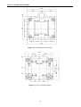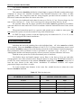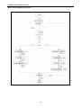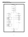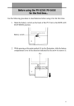
1
PAGE
SECTION 1: IMPORTANT INFORMATION
1-1
SECTION 2: SPECIFICATIONS/COMPONENT IDENTIFICATION
2-1
A.
TECHNICAL SPECIFICATION
SECTION 3: INSTALLATION PROCEDURES
A.
B.
C.
D.
E.
F.
G.
H.
I.
J.
K.
DIMENSION CLEARANCES
MACHINE FOUNDATION
MOUNTING BOLT INSTALLATION
DRAIN CONNECTION
ELECTRICAL INSTALLATION
WATER CONNECTION
STEAM CONNECTION
EXTERNAL CHEMICAL SUPPLIES
ELECTRICAL CONNECTIONS
CONTROL FUNCTION TEST
THEORY OF OPERATION
SECTION 4: OPERATING INSTRUCTIONS
A.
B.
C.
D.
LOADING DIRTY ITEMS
WASH
UNLOADING WASHED ITEMS
PROGRAM INSTRUCTIONS
SECTION 5: MAINTENANCE
A.
B.
THE MACHINE MAINTENANCE
THE CA DRIVE MAINTENANCE
2-2
3-1
3-1
3-2
3-4
3-5
3-6
3-7
3-8
3-8
3-9
3-9
3-10
4-1
4-1
4-1
4-2
4-2
5-1
5-1
5-5
SECTION 6: DECOMMISSIONING
6-1
SECTION 7: TROUBLE SHOOTING
7-1
SECTION 8: PARTS LIST
Anyone operation or servicing this machine must follow the safety rules in this manual.
Particular attention must be paid to the DANGER, WARNING, and CAUTION blocks which
appear throughout the manual
The lightening flash and arrowhead within the triangle is a warning sign
alerting you of the presence of dangerous.
The exclamation point within the triangle is a warning sign alerting you of
important instructions concerning the machine.
This warning symbol alerts you to the presence of possible dangerous drive
mechanisms within the machine. Guards should always be in place when the
machine is in operation.
This warning symbol indicated the presence of possibly dangerous chemicals.
Proper precautions should be taken when handling corrosive or caustic
material.
This warning symbol indicated the presence of hot surfaces that could cause
serious burns. Stainless steel and steam lines can become extremely got and
should not be touched.
This warning symbol indicates the presence of possible dangerous pinch –
points. Moving mechanical parts can crush and / or sever body parts.
Before servicing any equipment, make certain it is disconnected from the
electrical power source. Never allow operation of the machine when any
safety device is malfunctioning. Never bypass safety devices.
WARNING
Crush hazard.
Machine can lower suddenly
with power ON or OFF and
cause serious injury or
death.
Do not put any part of your
body under machine unless
you first secure safety
supports and lockout/tagout
machine.
WARNING!
Crush hazard. Machine can lower suddenly
with power ON or OFF and cause serious
injury or death. Do not put any part of your
body under machine unless you first secure
safety supports and lockout / tagout machine
IMPORTANT INFORMATION
SECTION 1
IMPORTANT INFORMATION
SA Series Washer – Extractors
The SA line is the industrial freestanding washer – extractor series of machines from B&C
Technologies Co., Ltd. It is an open pocket washer – extractor with a large door opening for easy
and quick loading and unloading. It has been developed for the institutional and industrial market,
and is suitable for commercial laundries, hotel, food processing plants, factories and other places
where laundry might be process.
The design allows for top performance at lowest possible operation cost and investment. The
flexible electronic control center ensures that maximum productivity is obtained.
The SA series utilizes high quality material, such as 304 (18/8) stainless steel in vital parts
in contact with the wash solution. It has a stainless steel cabinet for long life with easily removable
panels.
The key advantages of this series are the simplicity of the microprocessor and the electronic
AC drive system, which utilizes only one motor. The system allows for washing and extraction at
any speed and mechanical action to suit any textile fiber used today and tomorrow. A built in
suspension system isolate objectionable vibration and the high speed final extraction saves time and
energy in the finishing operation.
The main bearing is located the wash solution and will not be damaged, should the shell
seals leak. The machine is provided with two V – seals, which are very reliable and will last for
many years. The calculated life expectancy of the bearing is in excess of twenty years.
The five compartments, side mounted supply dispenser for powder and liquid detergents are
standard and the machine is designed to accept the connection of 5 additional external chemical
lines and pumps. More chemical connections are available as an option.
The SA series can be provided with tilt devices that can tilt the machine one or both ways.
This option provides for easy loading and unloading and unloading and saves hard labor.
The SA series is also prepared to accept the connection of water reuse systems. These
systems can be installed separate or on top of the machine. They are available in either single or
dual tanks for maximum savings of water up to 40%. The tanks can be equipped with or without
steam or electrical heat depending on installation and operation. The water reuse system is
programmable by the machines electronic control center.
Before Initial start up of a washer – extractor perform the following safety check:
A.
Make sure all electrical and plumbing connections have been made in accordance with
applicable codes and regulations.
B.
Make sure the machine is grounded electrically.
C.
Make sure the machine has flexible water fill and drain connections of the correct size, length
and type, with no kinks, and that they are securely attached and/or clamped.
D.
Make sure the transport brackets have removed.
1-1
IMPORTANT INFORMATION
Before machine is placed in operation, the door safety interlock must be checked for proper
operation as follows:
A.
When the washer is energized electrically and in operation, the loading door must be locked in
the closed position. Verify this by attempting to open the loading door when the machine is
operating. If necessary, check the door safety interlock and sensors for proper operation.
Consult the service manual, or call a qualified service technician if necessary.
B.
When the washers loading door is open, it should not be possible to start the machine. Verify
this by attempting to start the washer with the door open. Also, close the door without locking
it and verify that it is not possible to start the machine with the door not locked. If necessary,
check the door lock sensors for proper operation. Consult the service manual, or call a
qualified service technician. If additional information is required, contact your local distributor
or call the manufacturer of the machine
Before servicing any equipment, make certain it is disconnected from the
electrical power source. Never allow operation of the machine when any safety
device is malfunctioning. Never bypass safety devices.
To provide personal safety and keep the machine in proper working order, follow all
maintenance and safety procedures presented in this manual. If questions regarding safety arise.
Contact the factory immediately.
Use factory authorized spare parts to avoid safety hazards.
Operator safety
Never insert hands or objects into basket until it has completely stopped. Doing
so could result in serious injury.
To ensure the safety of machine operators the following maintenance checks must be
performed daily.
1.
Prior to operating the machine, verify that all warning signs are present and legible. Missing or
illegible signs must be replaced immediately. Make certain that spares are available.
2.
Check door interlock before starting operation of the machine, see safety checklist.
3.
Do not attempt to operate the machine if any of the flowing conditions are present.
3.1 The door does not remain securely locked during the entire cycle.
3.2 Excessively high water level is evident.
3.3 Machine is not connected to a properly grounded circuit.
Do not bypass any safety devices in the machine.
Never operate the machine with a bypassed or disconnected out – of – balance
switch. Operating the machine with severe out – of – balance loads could result
in personal injury and serious equipment damage.
1-2
IMPORTANT INFORMATION
Safe Operation Environment
Safe operation requires an appropriate operating environment for both the operator and the
machine. If questions regarding safety arise, contact the factory.
Environmental Conditions
1.
Ambient temperature.
Water in the machine will freeze at temperatures of 32 ºF (0 ºC) or below. Temperatures above
120 ºF (50 ºC) will result in more frequent motor overheating and, in some cases, malfunction or
premature damage to solid state devices that are used in the machines. Special cooling devices may
be necessary.
2.
Humidity.
Relative humidity above 90% may cause the machine’s electronics or motors to malfunction or
may trip the ground fault interrupter. Corrosion problems may occur on some metal components.
If the relative humidity is below 30% belts and rubber hoses may eventually develop dry rot. This
condition can result in hose leaks, which may cause hazards external to the machine in conjunction
with adjacent electrical equipment.
3.
Ventilation.
The need for make – up air openings for such laundry room accessories as dryers, ironers,
water heaters, etc. must be evaluated periodically. Louvers, screens, or other separating devices
may reduce the available air opening significantly.
4.
Radio Frequency Emissions.
A filter is available for machines in installations where floor space is shared with equipment
sensitive to radio frequency emissions. All machined that are shipped to CE countries are equipped
with this filter and comply with the EMI regulations.
5.
Elevation.
If the machine is to be operated at elevations over 3280 feet (100 meter) above sea level, pay
special attention to water levels and electronic settings (particularly temperature) or desired result
may not be achieved.
6.
Chemicals.
Keep stainless steel surfaces free of chemical residues to avoid corrosion.
7.
Water damage.
Do not spray the machine with water. Short circuiting and serious damage may result. Repair
immediately all seepage due to faulty gaskets, etc.
Do not place volatile or flammable fluids in any machine. Do not clean the
machine with volatile or flammable fluids such as acetone, lacquer thinners,
enamel reducers, carbon tetrachloride, carbon tetrachloride, gasoline, benzene,
naphtha, etc. Doing so could result in serious personal injury and / or damage to
the machine.
1-3
IMPORTANT INFORMATION
Machine Location
1.
Foundation.
The concrete floor must be of sufficient strength and thickness to handle the floor loads
generated by the machine at high extract speeds.
2.
Service / Maintenance Space.
Provide sufficient space to allow comfortable performance of service procedures and routine
maintenance. This is especially important in connection with machine equipped with AC inverter
driver. Consult installation instructions for specific details.
Replace all panels that are removed to perform service to perform service and
maintenance procedures. Do not operate the machine with missing guards or
with broken or missing parts. Do not bypass any safety devices.
Input and output services
1.
Water pressure.
Best performance will be realized if water or provided at a pressure of 30 – 85 psi (2.0 – 5.7
bar). Although the machine will function properly at lower pressure, increased fill time will occur.
Water pressure higher than 120 psi (8.0 bar) may result in damage to machine plumbing.
Components failure (s) and personal injuries.
2.
Optional Steam heating pressure.
Best performance will be realized if steam pressure is provided at a pressure of 30 – 80 psi (2.0
– 5.4 bar). Steam pressure higher than 125 psi (8.5 Bar) may result in steam components and may
cause personal injuries. For machines equipped with optional steam heat, install piping in
accordance with approved commercial steam practices. Failure to install the supplied steam filter
may void the warranty.
3.
Compressed Air.
For machines requiring compressed air service, best performance will be realized if air is
provided at a pressure of 80 – 100 psi (5.4 – 6.7 bar). Large capacity machines could experience
door seal failures if compressed air service is interrupted.
4.
Drainage System.
Provide drain lines or trough large enough to accommodate the total quantity of water that
could be dumped if all machines on the site drained at the same time from the highest attainable
level. If drain troughs are used, they should be covered to support light foot traffic.
5.
Power.
For personal safety and for proper operation, the machine must be grounded in accordance
with state and local codes. The ground connection must be to a proven earth ground, not to conduits
or water popes. An easy – access disconnect switch should be provided.
1-4
IMPORTANT INFORMATION
Ensure that a ground wire from a proven earth ground is connected to the
ground lug in the electrical junction box on this machine. Without proper
grounding personal injury form electrical shock could occur and machine
malfunctions may be evident. Computer – controlled machines must have a
proper ground to prevent computer malfunctions.
Always disconnect power and water supplies before a service technician performs any
service procedure. Where applicable, steam and / or compressed air supplies should also be
AC Inverter Drive
Machines equipped with AC drives require special attention with regard to the operating
environment.
1.
An especially dusty or linty environment will require more frequent cleaning of the AC drive
cooling fan filter and of the AC drive itself.
2.
Power line fluctuations from sources such as an interruptible power supplies (UPS) can
adversely affect machines equipped with the AC drive. Proper suppression devices should be
utilized on the incoming power to the machine to avoid problems.
3.
A clean power supply free from voltage spikes and surges is absolutely essential for machines
equipped with the AC drive. Nonlinear inconsistencies (peaks and valleys) in the power can
cause the AC drive to generate nuisance errors. If voltage is above 230V for 200V installations
or above 440V for 400V installations, a buck/boost transformer is recommended. If voltage is
above 240V or 480V, a buck / boost transformer is required unless the factory advises
differently.
4.
Sufficient space to perform service procedures and routine preventive maintenance is
especially important for machines equipped with AC drives.
Misuse
Even though this machine is an atmospheric vessel, never use it for any purpose other than
washing fabrics.
1.
Never wash petroleum – soaked rags in the machine. This could result in an explosion
2.
Never wash machine parts or automotive parts in the machine. This could result in serious
damage to the basket.
3.
Never stone wash in the machine. It could wear the basket and serious damage might occur to
the machine.
4.
Never use the machine for dying and with harsh chemicals that can cause corrosion and other
health hazards.
5.
Never allow children to play on or around this machine become trapped in the machine. Do
not leave children unattended while the machine door is open. These cautions apply to animals
as well.
1-5
SPECIFICATION/COMPONENT IDENTIFICATION
SECTION 2
SPECIFICATIONS/COMPONENT IDENTIFICATION
Delivery inspection
Upon delivery, visually inspect crate, protective cover, and unit for any visible shipping
damage. If the crate, protective cover, or unit are damaged or signs of possible damage are evident,
have the carrier note the condition on the shopping document before the shopping receipt is signed,
or advise the carrier of the conditions as soon as it is discovered.
Remove the crate and protective cover as soon after delivery as possible. If any damages
discovered upon removal of the crate and / or protective cover, advise the carrier and file a written
claim immediately.
Customer Service
If literature or replacement parts are required contact the source from whom the machine
was purchased or contact manufacturer.
A record of each machine is on file with the manufacturer. The serial number decal is
located at the rear of the machine. Always provide the machine’s serial number and model number
when ordering part or when seeking technical assistance.
NOTE:
Keep the manuals, installation instruction and the wiring diagrams which accompany
the machine in a safe place for ready reference. They have been included with the
machine at no charge. Additional copies are available at a nominal charge.
2-1
SPECIFICATION/COMPONENT IDENTIFICATION
A. TECHNICAL SPECIFICATION
SA 475 Technical Specifications
Units
MODEL
SA 475 Tilt
Metric
US
kg
lbs
475
216
A – Width
mm
in
2620
103.15
B – Height
mm
in
2540
100
C – Depth
mm
in
2475
97.44
D – Tilted Height (2 – tilt)
mm
in
3040
119.7
Net Weight
kg
lbs
8550
18849.5
Domestic shipping weight
kg
lbs
8806
19414
Export shipping weight
kg
lbs
9100
20062
Diameter
mm
in
1622
63.85
Depth
mm
in
1025
40.35
Volume
liters
cu ft
2118
74.8
Perforation size
mm
in
4.76
0.188
%
%
-
-
CAPACITY:
OVERALL DIMENSIONS:
WEIGHT AND SHIPPING INFORMATION:
CYLINDER INFORMATION:
Perforation open area
CYLINDER SPEEDS:
Wash
rpm
30
Distribution
rpm
50
Intermediate extraction
rpm
-
High extraction 1
rpm
270
High extraction 2
rpm
435
High extraction 3
rpm
500
Wash
g
0.8
Distribution
g
1.5
Intermediate extraction
g
-
High extraction 1
g
66
High extraction 2
g
171.5
High extraction 3
g
226.5
CENTRIFUGAL FORCES (Programmable) :
2-2
SPECIFICATION/COMPONENT IDENTIFICATION
Units
MODEL
SA 475 Tilt
Metric
US
Diameter
mm
in
1016
40
Height of door bottom above floor
mm
in
1611
63.43
1
1
DOOR OPENING AND HEIHGT:
DRIVE INFORMATION:
Number of motors
Number
Size of motor
kW
Hp
30
40
Hot water size
DN
in
50.8
2
Cold water size
DN
in
50.8
2
Additional water Inlet
DN
in
-
-
Average HOT water consumption / cycle
liters
gal
-
-
Average COLD water consumption / cycle
liters
gal
-
-
WATER INLETS:
DRAIN OUTLETS AND CAPACITY:
Number of drains standard
Number
2
Number of drains optional (water re – use)
Number
2
Drain size
mm
in
203.2
8
liter / cycle
g.p.m.
1050
277
Steam inlet size
DN
in
38.1
1-1/2
Required steam to heat bath 10 ºF (5.55 ºC) LOW
kg
lbs
-
-
Required steam to heat bath 10 ºF (5.55 ºC) HIGH
kg
lbs
-
-
kg / hr
lbs / hr
94
207
DN
in
12.7
1/2
cfm
0.01
0.1
Drain capacity
STEAM INLET AND CONSUMPTION:
Average steam consumption
AIR INLET AND CONSUMPTION:
Air inlet size
3
Average air consumption per cycle
m
2-3
INSTALLATION PROCEDURES
SECTION 3
INSTALLATION PROCEDURES
A. DIMENSION CLEARANCES
When installing the washer – extractor, it is important to allow adequate clearance on all
sides of the machine. When multiple machines are installed, it is important to allow for the specified
minimum clearances between machines. The following table shows recommended minimum
clearances for the various freestanding models.
NOTE:
The dimensions are approximate and subject to normal manufacturing tolerances. If
exact dimensions are required for construction purposes, request certified drawings
from the factory. We reserve the right to make changes at any time without notice.
Table.3-1 Dimension Clearances
UNTIS
Detail
SA Series Tilt
Metric
US
(A) Minimum rear clearance
mm
in
850
33.46
(B) Minimum clearance between machine and wall
mm
in
455
18
(C) Minimum clearance between machines
mm
in
850
33.46
(D) Minimum font clearance
mm
in
1200
47.24
Figure.3-1 Dimensions for construction
3-1
INSTALLATION PROCEDURES
B. MACHINE FOUNDATION
Thoroughness of details must be stressed with all foundation work to insure a stable unit
installation, eliminating possibilities of excessive vibrations during extraction.
The machine must be anchored to a smooth level surface so that the entire base of the
machine is supported and rest on the mounting surface.
NOTE:
Do not support the machine on only four points.
NOTE:
Freestanding washer-extractors do not require anchoring bolts unless specified by
state or local codes. However it is always recommended that the machines be
anchored.
Special care must be taken when machines are installed on an upper floor. Make sure that
the floors are designed to carry the static and dynamic loads of the machines.
Further vibrations should be taken into consideration so that the machine does not create
vibrations in the building. Static and dynamic loads on the floor or foundation are shown in the
table below. This table can be used as reference when designing floors and foundations. See figure
for mounting bolt layout measurement and pattern.
Ensure that the machine is installed on a level floor of sufficient strength and
that the recommended clearances for inspection and maintenance are provided.
Never allow the inspection and maintenance space to be blocked.
Table.3-2 Machine Foundation
Machine
SA 475
Static floor
load
Static
pressure
Dynamic floor
load
Max
dynamic load
kN
lbs
kN/m2
lbs - ft2
kN
lbs
kN
lbs
67
15,000
11.3
234
1,253
-
-
-
3-2
Dynamic
pressure
kN/m2 lbs - ft2
3.2
66.7
INSTALLATION PROCEDURES
Figure.3-2 Foundation Bolt Location
Figure.3-3 Type Grouting Pattern
3-3
INSTALLATION PROCEDURES
C. MOUNTING BOLT INSTALLATION
All washers – extractors must be secured by the use of machinery anchor bolts. High
strength machinery anchors should be embedded in 3,500 psi (24,000 N/m2) reinforced concrete.
See Figure. For detailed information regarding the machine anchor bolt, see the instructions
included with the anchor bolts themselves. The following information is just an example.
After the concrete has cured, proceed as follows:
Select a carbide
drill bit with a
diameter equal to
the anchor diameter.
Drill hole to any
depth exceeding the
desired embedment.
Clean hole or
continue drilling to
accommodate drill
fines (concrete
dust). Please wear
eye protection.
Drive the anchor
into the hole
through material
being fastened until
washer is flush with
material.
Expand bolt by
tightening the
anchor 3 to 5 turns,
or to the specified
torque
requirements.
Figure.3-4 Mounting Bolt Installation
Place the machine adjacent to the foundation. Do not attempt to move it by pushing on the
sides.
1.
Remove the wood skid by unscrewing the carriage bolts holding it to the bottom frame of the
machine.
2.
Carefully place the machine over the anchor bolts. Raise and level it 1/2 inch above the floor
on four points, using spacers that can be removed.
3.
Fill the spaces between the machine base and floor with machinery grout. Grout completely
under all frame members. Remove front panel and rear panel to gain access to all frame
members. Force grout under the machine base until all voids are filled.
4.
Remove the spacers carefully, allowing the machine to settle into the wet grout.
5.
Attached the mounting bolt washers and lock nuts to the anchor bolts after the grout has
hardened. Tighten the lock nuts by even increments – one after the other – until all are
tightened evenly and the machine is fastened securely to the floor. The nuts should be
tightened in a diagonal fashion, which will help ensure equal tension at all anchor points.
6.
Remove the four red transportation brackets which secure the moving component of the
machine during shipping.
3-4
INSTALLATION PROCEDURES
Front side the machine
Rear side the machine
Figure.3-5 Location of transportation brackets inside the machine
D. DRAIN CONNECTION
A drain system of adequate capacity is essential to the machine performance. Ideally the
water should empty through a 4 inches vented pipe directly into a sump or floor drain.
A flexible connection must be made to a vented drain system to prevent an airlock or siphon
effect. If proper drain size is not available or practical, a surge tank is required. A surge tank in
conjunction with a sump pump should be used when gravity drainage is not possible, such as in
below – ground – level installations.
Before any deviation from specified installation procedures is attempted, the customer or
installer should contact the manufacturer. Increasing the drain hose length, installing elbows, or
causing bends will decrease drain flow rate and increase drain time, impairing machine
performance. If the drain arrangement is inadequate, the machine will not extract and will not
discharge water properly.
See table below for specific drain information.
Table.3-3 Drain Sizing
Units
Detail
Drain connection Size
Drain flow capacity
Minimum drain it size
SA Series
Metric
US
mm.
in
215
8 1/2
liters / min
g.p.m.
-
-
liters
gal
-
-
3-5
INSTALLATION PROCEDURES
E. ELECTRICAL INSTALLATION
The AC drive requires a clean power supply free from voltage spikes and surges. A voltage
monitor should be sued to check incoming power. The customer’s local power company may
provide such a monitor.
The AC drive provides for an internal circuit breaker. A separate circuit breaker governs the
control circuit.
If input voltage measures above 230V for a 200V drive, or above 440V for a 400V drive,
either ask the power company if their representative can lower the voltage or install a step – down
transformer kit available from the manufacturer. Voltages above 250V and 490V require additional
measures. Contact the distributor or the manufacturer for assistance.
This machine must be installed, adjusted, and serviced by a qualified electrical
maintenance personnel familiar with the construction and operation of this type
of machinery. They must also be familiar with the potential hazards involved. If
this warning is not observed, personal injury or equipment damage resulting in
voiding the warranty may result.
When controlling the AC drive with a parameter unit, the machine’s computer
and its safety features are bypassed. This would allow the basket to rotate at
high speeds with the door open. When using a parameter unit to control the AC
drive, a large sign should be placed on the front of the machine warning people
of the imminent danger.
Never touch terminals or components of the AC drive unless power is
disconnected and the “CHARGE” indicator LED is off. The AC drive retains
potential deadly voltage for some time after the power is disconnected. There
are no users – serviceable parts inside the AC drive. Tampering with the drive
will void the warranty.
Dangerous voltages are present in the electrical control boxes and at the motor
terminals. Only qualified personnel familiar with electrical test procedures test
equipment, and safety precautions should attempt adjustments and
troubleshooting. Disconnect power from form the machine before removing the
control box cover, and before attempting any service procedures.
Table.3-4 Table for breaker size
Machine
SA 475
NOTE:
200 – 240V
380 – 480V
Max Amps
Breaker
Wire Size
Max Amps
Breaker
Wire Size
110 A.
150 A.
2 AWG.
35 Sq. mm.
60 A.
100 A.
6 AWG.
16 Sq. mm.
Wire sizes shown are for copper, THHN, 90 conductors per NEC article 310 (USA).
3-6
INSTALLATION PROCEDURES
The machine should be connected to an individual branch circuit not shared with lighting
or other equipment.
The connection should be shielded in a liquid tight or approved flexible conduit with proper
conductor of correct size installed accordance with National Electrical Code (USA) or other
applicable codes. The connection must the wiring diagram provided with the machine. See the
Electrical Connection data Chart for correct wire sizes.
Use wire sizes indicated in the chart for runs up to 50 feet (15 m). Use next larger size for
runs of 50 to 100 feet (15 – 30 m). Use 2 sizes larger for runs greater than 100 feet (30 m).
For personal safety and for proper operation, the machine must be grounded in accordance
with state and local codes and in the USA in accordance with the National Electrical Code, article
250 – 96.
The ground connection must be to a proven earth ground, not to conduit or water pipes. Do
not connect the system is used, the neutral (N) leg at the terminal strip.
If a DELTA supply system is used, the high leg may be connected to L1, L2 or L3, as the
machines are equipped with control transformer.
F. WATER CONNECTION
Individual hot and cold plumbing lines with individual shut – off valves must be available
to the machine. Hot water should be minimum of 160 ºF (70 ºC). If lower temperature water is used
the machine should be equipped for steam heating to heat the wash solution to desired temperature.
Best performance will be realized if water is provided at a pressure of 30 – 85 psi (2 – 7 bar).
Although the machine will function properly at lower pressures, increased fill times will occur.
Flush the water system for at least two minutes prior or initial use.
Use flexible hoses and install separate screen filters in the lines to keep rust and other
foreign particles out of the solenoid valves. Hang the hoses in a large loop. Do not allow the hoses
to link. The water connections to the machine should be supplied by a hot and cold water line of
least the sizes shown in the table below. Installation of additional machines will require
proportional larger water lines, see table.
To avoid eventual water hammer in the water line, suitable devices to reduce the water
hammer should be installed.
Table.3-5 Table for drain size
NUMBER OF MACHINES
SUPPLY LINE PIPE SIZES
SA 475
1
2
3
4
5
DN
-
3-7
Inch
1/2
1/2
1/2
1/2
1/2
INSTALLATION PROCEDURES
G. STEAM CONNECTION
Never touch internal or external steam pipes, connections, or components.
These surfaces can be extremely hot and will cause severe burns. The steam
must be turned off and the pipe, connections, and components allowed to cool
before the pope can be touched
For machines equipped with optional steam heat, install piping in accordance with approved
commercial steam practices. Steam requirements are shown in the table below. Failure to install the
supplied steam filter may void the warranty.
Table.3-6 Table for steam size
MODEL
Units
STEAM INLET and CONSUMPTION:
SA 475
Metric
US
Steam inlet size
DN
in
1 1/4
1 1/4
Required steam to heat bath 10 ºF (5.55 ºC) LOW
kg
lbs
-
-
Required steam to heat bath 10 ºF (5.55 ºC) HIGH
kg
lbs
-
-
Average Steam consumption per cycle
kg
lbs
-
-
H. EXTERNAL CHEMICAL SUPPLIES
Wear Eye and hand protection when handling chemicals. Always avoid direct
contact with raw chemicals. Read the manufacturer’s directions for accidental
contact before handling chemicals. Ensure that an eye – rinse facility and an
emergency shower are within easy reach. Check at regular intervals for
chemical leaks.
The following procedures must be observed when connecting any chemical injector to the
washer – extractor. See the figure for a typical supply injection system setup. Undiluted chemicals
dripping can damage the machine. Therefore, all chemicals supply dispenser pumps should be
mounted below the washer’s injection point. All dispensers tubing should also run below the
injection point. Loops do not prevent drips if these instructions are not followed. Failure to follow
these instructions could damage the machine and void the warrant.
The supply compartment on the SA models is located on the front of the machine. Supply
cups can be accessed by opening the dispenser lid. The supply cups can be removed and filled as
desired. Supply compartments are numbered 1, 2, 3 and 4 from the left of the machine to the right
External supply connections for the SA washer – extractors are located on rear of the machine.
Hose connections should be made via the threaded connectors. See figure.
1.
Remove plug from base. See figure. Plugs are assembled inside the tubing ring.
2.
Install strain relief, included in the seal nut.
3.
Insert tubes through base, do not remove cups. Tube should extend into the plastic cup, with
the exception of the softener be routed to the outside of the cup.
4.
Tighten the seal nut to prevent tubing from escaping the assembly.
3-8
INSTALLATION PROCEDURES
I. ELECTRICAL CONNECTIONS
Connection terminals are located in the rear control box for output signals to the chemical
injection supply pump.
Terminals SUPPLY 1 through SUPPLY 4 provide contact closings for external chemical
supply pumps. The contact rating is maximum 3 amps at 24 – 220 V 50/60 Hz.
Do not attempt to increase fuse rating as this cause damage to the washer – extractor
circuitry. Any injection system pump, which requires 24 – 220 V AC, must be powered by a
separate external power source.
Attempting to obtain power from the machine terminals may damage the
machine circuit and / or the chemical injection system. Consult the chemical
injection supply system instructions for operational details.
J. CONTROL FUNCTION TEST
The machine should be cleaned after the installation is complete. A function test should
then be executed on the unloaded machine as follows:
1.
Check the proper supply for such characteristics as correct voltage, phase, and cycles to be
certain they are correct for the machine.
2.
Open manual shut – off water valves to the machine.
3.
Press Emergency Stop button.
4.
Apply power to the machine.
5.
Release the Emergency button.
6.
Check the door interlock before starting the machine.
a.
Attempt to start the machine with the door open. The machine should not start with the
door open.
b.
Close the door without locking it and attempt to start the machine. The washer should not
start with the door unlocked.
c.
Close and lock the door and start a cycle. Attempt to open the door while the cycle is in
progress. The door should not open.
If the door lock and interlock are not functioning properly, call a service technician.
7.
For standard processing, select program 30 by pressing key 3 and key 0 on the keypad. Then
press enter and the Start key. Run the complete program, checking operation of water inlet
valves, drain, and extract functions. Program 30 is a test program that goes through most
machine functions.
8.
Cylinder rotation must be counter clockwise in the extract step. If rotation is not correct,
disconnect the power to the machine. A qualified technician must reverse any two leads
between the AC drive and the motor.
3-9
INSTALLATION PROCEDURES
K. THEORY OF OPERATION
The SA models use a single – speed motor to drive the cylinder is supported via V – belts in
all speeds. The cylinder is supported by two spherical roller bearings located in a bearing housing
made of cast iron.
The motor is controlled by the computer control located in the front and the AC inverter
drive located in the rear panel. Any speed can be programmed for any wash cycle. Some speed
ranges are blocked out for programming due to safety reasons. This speed range is not important
and normally speeds for wash or extraction are not selected within this range. Any wash speed in
the range of 10 – 50 RPM and extraction speeds 150 – 660 maximum RPM can be programmed.
Further any reversing action can be programmed. Normal reversing action is 18 seconds forward,
pause for 3 seconds, and 18 seconds reverse. Any temperature between 70 ºF to 200 ºF (20 – 95 ºC)
can be programmed. Any water level in the range of the machine parameters can be programmed is
centimeters. The computers will automatically provide safety levels for steam injection and door
operations.
Water entry into the machine is through electromagnetic water valves controlled by the
computer. The computer also controls the drain, supply dispenser, any external liquid supplied,
steam injection and any other vital functions of the wash program. The computers can even record
cycles and data of importance that could be used for maintenance purpose.
The steam, if installed is injected in the bottom of the shell via a steam injector. The steam is
controlled by a steam valve that is programmed by the micro computer.
The cylinder is perforated, allowing water to pass through and drain from within during
drain and extract steps. Lifting ribs inside the cylinder lift the load from the wash solution and allow
the load to tumble and falling back into the solution when the load reaches the approximate 10 – 11
o’clock or 1 – 2 o’clock positions. This mechanical action removes soil from the fabric.
Furthermore, the lifters are perforated on the top so that water can cascade over the goods and wet
them quickly. This reduces water consumption as water is picked up at the cylinder’s lowest point
and lifted and splashed over the goods at the highest point as the cylinder rotates.
A stainless steel door is provided for loading and unloading. A door lock system prevents
operation of the machine when the door is open. The door is locked during operation utilizing an air
cylinder and a manual latch for safety reasons. The door lock is provided with magnetic sensor to
indicate that the machine is locked and provide for start of the machine when the door is closed and
locked.
The AC drive, contractor, circuit overload protectors, input power supply connections,
external supply connection, and control transformer are behind a cover of the rear of the machine.
The supply dispenser is mounted on the front of the machine and is accessed by unlatching
the cover door. Supplies, both liquid and powder may be added by pulling the dispenser cups out
and placing the appropriate supply in each. Supplies are flushed into the machine at the proper time
in the cycle, controlled by the microcomputer.
Holes are provided at the rear of the machine for connection to an external, central liquid
supply unit. Electrical connections are provided for the liquid supply unit on a terminal strip inside
the rear control module.
3-10
OPERATING INSTRUCTIONS
SECTION 4
OPERATING INSTRUCTIONS
A. LOADING DIRTY ITEMS
STEP 1: Select switch F turn to “Manual”.
STEP 2: Select switch C turn to “Load” and release.
STEP 3: Press and hold button G to open the door.
STEP 4: Load dirty items.
STEP 5: Press and hold button H to close the door.
STEP 6: To return the machine to centre position use switch C turn to “Unload” and release.
A
B
C
D
F
E
G
H
Figure.4-1 Controller Side
B. WASH
STEP 1: Select switch F turn to “Auto” (Air cushion will rise up and door can not be opened).
STEP 2: Select the program at B and press “START”.
4-1
OPERATING INSTRUCTIONS
C. UNLOADING WASHED ITEMS
STEP 1: Select switch F turn to “Manual”.
STEP 2: Select switch C turn to “Unload” and release.
STEP 3: Press and hold button G to open the door.
STEP 4: Unload clean items. Use button D for jog cylinder “Forward”, Use button E for jog
cylinder “Reverse”.
STEP 5: Press and hold button H to close the door.
STEP 6: To return the machine to centre position use switch C turn to “Load” and release.
NOTE:
Incase the case of needing to stop the machine (Emergency). Can press
“EMEGENCY STOP” (A)
D. PROGRAM INSTRUCTIONS
WC03 Computer
The WC03 Computer is a powerful and programmable solid state controller. Up to 30
programs, each with up to 15 cycles can be freely programmable. In addition, the WC03 can be
programmed in 6 languages – English, Italian, German, Spanish and French. The water level can
be programmed, and is accurate to 1 cm (0.4 in). Spin speeds are fully programmable in RPM. In
the event of power failure, the operator is prompted to continue the cycle, or abort it.
4-2
OPERATING INSTRUCTIONS
Keypad
INS
1
DEC
2
INC
3
TEMP
4
LEVEL
5
TIME
6
Number key, Insert Key. Enables a new cycle to be inserted in an existing program
during programming. During operation, press and hold for cylinder RPM.
Number key, Decrement Key. Lowers the current value during programming mode.
Number key, Increment Key. Raises the current value during programming mode. If
pressed simultaneously with the TEMP or LEVEL key, allows temporary
modification.
Number key, Temperature Key. Allows temporary modification of the target
temperature if used with the INC and DEC keys. Displays current temperature in
wash cylinder.
Number key, Level Key. Allows temporary modification of the target water level if
used with the INC and DEC keys. Displays current water level in wash cylinder.
Number key, Time Key. Displays the watch dog timer value for the current step.
7
8
Number keys.
9
PAUSE
0
UNLOCK
DOOR
Number key, Pause Key. If pressed during operation, pauses the wash program
indefinitely. Not active during distribution or spin.
On SA series equipment, this button unlocks the door and allows it to open. Not
used on other equipment.
4-3
OPERATING INSTRUCTIONS
ADVAN
Advances to the next program step. During final spin, the remainder of the spin is
aborted. If pressed before starting a program, it allows the operator to begin the
program at any segment. During programming, skips to the next segment.
ENTER
Confirms settings in creation and editing of wash programs. During operation, shows
the current segment or program number.
DEL
Deletes any selection or setting.
RESET
STOP
Terminates the current activity (operation or programming). While the machine is
powered but not executing a program, can be pressed with RESET to see the current
firmware version.
START
Starts execution of the currently selected wash program. Restarts a paused program.
When pressed with RESET, function codes can be entered to program and setup the
machine. See the quick reference list on the next page.
4-4
OPERATING INSTRUCTIONS
To access this mode, press START and RESET together, then at the prompt, key in the
desired number.
Programming
12
27
45
Programming cycles
Creation of Programs
Programming motors
System Setup
118
181
201
205
207
209
210
211
212
213
214
215
216
217
218
219
220
221
222
223
225
230
Disable Machine
Resets controller – erases all memory
Language option (1 – Italian, 2 – English, 3 – German, 4 – Spanish, 5 – French)
16 or 24 outputs
Maximum RPM
Temperature Hysterisis (min 1 deg, max 10 deg) Default is 3 deg.
Display temperature in degrees C
Display temperature in degrees F
Maximum water level that can be set (10 – 100 cm.)
Minimum water level for heating (2 – 30 cm.)
Display number of hours of operation
Display total number of washes
Display number of washes since the last maintenance
Reset maintenance request
Display and set number of washes until maintenance request
Spin slow down time (40 – 200 sec)
Erases Programs and cycles
Copy from control to memory card
Copy from memory card to control (only programs and cycles)
Copy from memory card to control (programs, cycles, and parameters)
Disables Advance Key
Maximum water level allowed during spin (2 – 60 cm.)
Highlighted items are safety related and should not be changed.
Do not alter these values without consulting a qualified technician.
Programming
Programming the WC03 takes place on three levels:
1.
Programming motors (45)
Allows 15 different operating modes to be created for each mode, the clockwise rotation time,
the counterclockwise rotation time and the pause time can be programmed.
2.
Programming the cycles (12)
For each sequence of steps, creates a sequence of events in which various functions can be
activated or deactivated (drain, cold fill, spin, etc.). Going from one step to another may require
reaching a water level or temperature, or a time value. There are five different programmable cycle
4-5
OPERATING INSTRUCTIONS
types: Prewash, Wash, Rinse, Spin and Unroll (Shakeout). Each cycle can be assigned a number
between 1 and 99.
3.
Creation of Wash Programs (27)
Consists of putting the various cycles as programmed above together to form a complete wash
program. Up to 30 programs can be stored each with 15 cycles (segments).
Motor Programming
To access the motor programming mode, press START and RESET together. The display shows:
NO. ?
Enter 45 at this prompt, followed by the ENTER key. For two seconds, the display will show:
* EDIT MOTORS *
You are then asked to enter the motor routine number to be programmed (1 – 15).
MOTOR NO.
You may now enter the number and press the ENTER key. There are now two cases:
1.
The motor routine does not exist.
2.
The motor routine does exist
4-6
OPERATING INSTRUCTIONS
New motor routine
In this case, you are prompted to enter a clockwise rotation time with this message:
T. FORWARD = S
Enter the desired time in seconds, followed by the ENTER key. The display will change
T. PAUSE = S
Enter the desired time in seconds, followed by the ENTER key. The display will change
T. BACKWARDS = S
Enter the counterclockwise time in seconds, followed by the ENTER key. The display will show:
STORE?
Pressing ENTER will store the motor timing routine and the display will change to request a new
access code:
NO. ?
Enter 45 at the prompt to program additional motor timing sequences as required. Pressing RESET
instead of ENTER will exit programming.
Editing an Existing Routine
If the motor routine number you entered id already present, the display will show:
ALREADY EXISTS!
Pressing the ENTER key again displays the forward rotation time:
T. FORWARD = XXs
Pressing the INC and DEC keys allow you to step through the values for Forward, Pause, and
Backwards. Pressing ENTER will allow you to modify the value on the display
After having viewed or modified the backwards value, pressing the INC or ENTER key displays:
STORE?
Pressing ENTER confirms the changes mode (if any) and exits programming. Pressing RESET
exits the current programming mode and leaves the existing values as they were.
4-7
OPERATING INSTRUCTIONS
Notes on Motor Programming
There are a number of different moles available for motor programming:
1. Forwards – Pause k – Backwards
T. FORWARD = XXs
T. PAUSE = XXs
T. BACKWARDS = XXs
2. Forwards – Pause
T. FORWARD = XXs
T. PAUSE = XXs
3. Forwards
T. FORWARD = XXs
T. PAUSE = SO
4. Pause – Backwards
T. FORWARD = SO
T. PAUSE = XXs
T. BACKWARDS = XXs
5. Backwards
T. FORWARD = SO
T. PAUSE = SO
T. BACKWARDS = XXs
The minimum pause time that can be programmed between forward and backwards is 2 seconds.
Cylinder speed is programmed during cycle programming. In this mode, step can be programmed
with different values if desired.
4-8
OPERATING INSTRUCTIONS
Motor Programming Flow Chart
4-9
OPERATING INSTRUCTIONS
Cycle Programming
Cycle libraries can be created for later use in the wash programming step. When the machine is
stopped, press the START and RESET buttons together. The display is:
No. ?
Using the keypad, type 12 and press ENTER. For two seconds, the display shows:
* EDIT CYCLES *
The message for choosing the programming cycle is then displayed:
PREWASH = ?
Pressing INC or DEC will show the other cycle types in succession:
WASH = ?
SPIN = ?
RINSE = ?
UNROLL = ?
When the cycle type you wish to edit is displayed, press ENTER to begin creating or editing of the
cycle. As an example, we will go through programming a prewash cycle.
PREWASH = ?
Using the numerical keypad, enter the cycle you wish to create or modify. After you have entered
the number and pressed ENTER, there are two possible cases:
New Cycle Creation
If the cycle you chose does not exits, you will be taken directly into the programming mode. For
two seconds, the display will show:
START STEP 1
The display then changes to:
COOLING? NO
You can now define for step 1 whether the cool down feature is activated. If you wish to activate
cool down, press ENTER, and the display changes to:
COOLING? YES
4-10
OPERATING INSTRUCTIONS
To implement the cool down phase, five additional parameters must be entered. These are discussed
in the next section. If you do not wish to activate the cool down phase press INC. the display will
show:
BALLOAD? NO
You can now define for step 1 whether the load balancing is enabled. Load balancing is essentially
a modulated fill. A target temperature can be programmed and the machine will use a combination
of the hot water fill valve and the cold water fill valve to maintain a given temperature. If you wish
to activate temperature controlled fill, press ENTER. The display will change to:
BALLAD? NO
To implement temperature controlled fill, four additional parameters must be entered. These are
discussed in the next section. If controlled fill, press INC. The display will:
DRAIN? NO
To activate the Drain and end Step 1, press ENTER, pressing INC or DEC will scroll through the
other functions to end the step. The step can end with a Drain, a Water Level, a Water Temperature,
or an elapsed Time. Selecting on of the functions by pressing ENTER changes the display and
prompts you to enter a value for the particular function.
EXAMPLE:
LEVEL NO
ENTER
LEVEL = cm
Type the required value in using the numerical keypad and press ENTER. In the event that you
choose a level or a temperature to end the step, you will be prompted with:
WDT = NO
This is the Watch Dog Timer. Press ENTER to set the value.
WDT = m
Set the time in minutes, press ENTER
WDT = s
Set the time in seconds, press ENTER. This timer provides a time in which the temperature or
water level you have programmed can be reached. If the level or temperature cannot be reached in
the given amount of time, the wash program will continue. Be sure do enter a time that is
reasonably longer than the presumed time for filling or heating.
4-11
OPERATING INSTRUCTIONS
The display now shows:
STORE?
Pressing STOP will cancel the programming and abort any parameters you have entered. To save,
press ENTER. Now the start of a new step will be indicated. For two seconds the display show:
STAET STEP 2
The display then changes to:
COOLING? NO
At this point, you may continue assign steps to the cycle using the same programming sequence as
used for step 1. If programming is complete, press STOP. the
PREWASH = ?
You may now program another Prewash cycle, or select one of the other cycle types and continue
programming. To exit from cycle programming, press RESET.
Cool down Phase
The cool down phase allows you to specify a temperature to reach before draining the machine.
There are five parameters to be programmed: Minimum Level, Maximum Level, Temperature,
WDT, and Motor. The cool down phase operates as follows:
¾
The water is drained to the minimum level as mentioned above.
¾
Cold water is then added up to the maximum level as mentioned above, and the
temperature is monitored.
¾
Draining and filling continue until either the temperature is reached, or the WTD
(watch dog timer) has expired.
The motor profile chosen is active throughout this step.
Load Balancing / Temperature Controlled Fill
The Load Balancing option is essentially a temperature controlled, or modulated, fill. Cold and Hot
water are added to the machine while the temperature and level are monitored. Four parameters
must be entered: Level, Temperature, WDT, and Motor. The option functions as follows: Cold or
Hot water is added to the machine depending upon the temperature set (Hot if the water temperature
is lower than programmed or cold if it is higher) until the programmed water level is reached. Then
the next step of the cycle can begin. During this phase, the WDT (watch dog timer) is active, which
will flag a fault if the fill time is longer than the programmed WDT. The chosen motor routine is
active for this entire process.
Heating
Throughout the programming of the steps, when heating is inserted, this tells the control to regulate
the temperature. In a step that ends with a required temperature, the heating value must be greater
than or equal to the step ending temperature. For example, if 50 degrees was set for heating, but 70
degrees was required to end the step, the machine could never reach 70 degrees, causing a fault
from the Watch Dog Timer. In cases where the step is ended by time or level, the temperature can
4-12
OPERATING INSTRUCTIONS
be selected from 30 to 93 degrees C.
Motor
For the motor function, after pressing ENTER, you are asked to enter a motor function. When you
have confirmed the selection with ENTER, the display shows:
RPM =
Enter the desired value and press ENTER to confirm. In Prewash, Wash, Rinse, and Unroll, the
maximum speed is 100 RPM. Use Programming Code 207 to set maximum Spin RPM.
Programming Sequence for Prewash, Wash, Rinse and Unroll, the programming sequence is as
follows:
»
Cooling
»
Load Balanced (Temp Controlled Fill)
»
Drain
»
Cold Water
»
Hot Water
»
Heating
»
Detergent 1
»
Detergent 2
»
Detergent 3
»
Detergent 4
»
Hard Water
»
Relay 16 (Detergent 7)
»
Relay 11 (Aux Fill)
»
Relay 12 (Injection Flush)
»
Relay 13 (Drive Balancing)
»
Motor
»
Relay 17 (Detergent6)
»
Relay 18 (Not used)
»
Relay 19 (Detergent 8)
»
Relay 20 (Aux Drain)
»
Relay 21 (Not Used)
»
Relay 22 (Not Used)
»
Relay 23 (Not Used)
»
Relay 24 (Not Used)
4-13
OPERATING INSTRUCTIONS
Editing an existing cycle
If the cycle you chose already exists, the display will show:
ALREADY EXISTS!
At this point, four choices are possible:
1.
Choose another cycle by pressing STOP
2.
Access the existing cycle by pressing ENTER. In this case, INC or DEC will display the
various segments, and the configuration can be modified by using the ENTER and RESET
keys as described in the previous section.
3.
Insert one or more steps. To do so, scroll through the steps by using the ADVAN key. The
display will show START STEP 1 for two seconds, followed by ALREADY EXISTS! To
insert a step, press INS and to:
START STEP 1
Followed by:
COOLING? NO
You may now proceed to program the new step using the techniques described earlier. After
confirming storage of the new steps, press STOP.
Remove one or more of the steps from the existing ones. Proceed by pressing ADVAN as describe
above in (3). When the message appears after the step you wish to remove,
ALREADY EXISTS!
Press the DEL key. The following message appears:
DELETE?
To confirm deletion of the step, press the ENTER key or press RESET to cancel the operation.
After confirmation, press the STOP key to exit.
Each cycle can comprise a maximum of 100steps. A total of 400 steps can be programmed.
Wash Program Creation
When the machine is stopped, press the START and RESET buttons together. The display is:
No. ?
Using the keypad, type 27 and press ENTER. For two seconds, the display shows:
EDIT PROG. No
At this prompt, type the program number you wish to create or edit, followed by the ENTER key.
Again, two situations are possible:
4-14
OPERATING INSTRUCTIONS
¾
The Program does not exist and must be created.
¾
The Program already exists and can be viewed and modified.
Creating a new Wash Program
The display reads.
NOT FOUND!
For two seconds, then:
C1>?
At this prompt, press ENTER. The display changes to:
C1>PREWASH = ?
Using the INC or DEC key, you can select the type of cycle to insert: Prewash, Wash, Spin, Rinse,
and Unroll. For example, if you wish to insert a wash cycle you have named 3; press INC until the
display changes to:
C1>WASH = ?
Confirm the selection by pressing ENTER. The display changes to:
C1>WASH = No.
Type 3 on the keypad, the press ENTER. Wash 3 is now stored as the first segment of the program.
The display will prompt you to enter a second cycle:
C2>?
At this prompt, press ENTER. The choice of cycle will be displayed as previously. Programs can
be compiled with up to 15 cycles chosen from those in available in the cycles library. The same
cycle can be used repeatedly in a wash program. After you are through programming, and have
confirmed the last cycle, press STOP to terminate programming. The display then shows:
STORE?
Press ENTER to store the program. Press RESET to cancel and return to the beginning if while
programming, you enter a wash cycle that does not exist, the following message will appear.
NOT FOUND!
Since the wash cycle doesn’t exist, you will have to create it before adding it to a wash program.
4-15
OPERATING INSTRUCTIONS
Editing an Existing Program
In the event the wash program already exists, the display will change to:
ALREADY EXISTS!
For two seconds, followed by the display of the program contents. For example:
C1>RINSE = 1
By using the INC or DEC keys, the various cycles comprising the wash program can be viewed.
The program can be modified, and cycles can be added or deleted.
Deleting a Cycle
Using the INC and DEC keys, find the cycle you wish to delete. While the cycle is displayed, press
the delete key, and then press the STOP key when the display changes to:
STORE?
Confirm by pressing the ENTER key. The cycle in question will be deleted, and the cycles
following will be decremented by one.
STORE?
Inserting a Cycle
To insert a cycle, use the INC and DEC keys to find the cycle that will follow the cycle you are
about to insert. The new cycle will be inserted just before the cycle displayed. Now press the INS
key, the request to enter a new cycle will be displayed:
C->?
Press ENTER to confirm that you wish to insert a new cycle:
Cn> PREWASH=?
Use the INC and DEC keys to reach the required cycle and press ENTER to confirm. You will
then be asked to enter the cycle number:
Cn> PREWASH=No.?
After entering the cycle number and pressing the ENTER key, you can leave programming by
pressing STOP. The display changes to:
STORE?
Press the ENTER key to store the altered program. All the following cycles will be incremented by
one. If you don’t want to change the program, press the RESET key rather than the ENTER key.
This will cancel all modifications made.
4-16
OPERATING INSTRUCTIONS
Wash Program Creation Continued
4-17
OPERATING INSTRUCTIONS
After power is applied to the machine, and the internal diagnostics are complete, the machine is
ready for a program to be chosen. The display will show:
PROGRAMN._
Using the keypad, type the number of the program you wish to run followed by the ENTER key.
The display will change to show the fist cycle of the selected program:
PRWH 1 EXECUT.?
Press START to execute the program, or RESET to return to program selection. While the
program is executing, the display shows the current segment of the program, and the ending
condition of the segment. See the following examples:
Level
If the end requirement of the segment (cycle) is a particular water level, the display will show:
RINSE1 LVL = cm 12
cm 12 is the actual water level in the machine (12 centimeters). Pressing the LEVEL key shows,
for 3 seconds, the required value to advance. If INC or DEC is pressed, you can temporarily modify
the value for the current step. Pressing TEMP allows you to see the current temperature of the
water. Pressing the TIME key shows the watch dog timer (WDT) value for the current step.
Temperature
If the end requirement of the segment is a particular temperature, the display will show: where
35C is the actual temperature of the wash solution.
WASH3 TEMP = 35 C
By pressing TEMP the display will change, for 3 seconds, show the required step temperature for
advance. Pressing INC or DEC allows modification of the value for the step. Pressing LEVEL
allows you to see the current water level. Pressing the TIME key shows the watch dog timer
(WDT) value for the current step.
Time
If the end this case, the display shows: the remaining time left in the step.
RINSET1 T =2m 30s
INC and DEC allow you to add or subtract minutes for the current cycle. TEMP allows you to view
the current water temperature, and LEVEL shows the current water level.
NOTE:
During heating, fill and drain phases, the WDT (watch dog timer) is activated. If the
phase does not complete before the timer expires, an alarm will be displayed
indicating that the particular phase did not complete within the maximum time
allowed.
4-18
OPERATING INSTRUCTIONS
Single Step Execution
A single step or cycle of a wash program can be executed. At the main prompt, enter zero for the
program number. For two seconds, the display changes to:
SINGLE CYCLE
Then, using the INC and DEC keys, you may choose the cycle you wish to run (PREWASH,
WASH, RINSE, SPIN, UNROLL). When you have selected you cycle, confirm by pressing
ENTER. The display changes to:
RUN?
Pressing the START key will start the machine.
Partial Program
A program can be partially run. After selecting the program you wish to execute, the display will
show:
RUN?
Instead of pressing ENTER to execute the program, press the ADVAN key. The cycles within the
program will be displayed incrementally. Choose the point at which you would like to begin, and
press the START key. The machine will begin operation from this point.
Displaying the Current Program and Step
While the machine is in operation, pressing then ENTER key will cause the display to show the
current program number and step.
PRG 1 STP 3
Soak
You can insert a pause at any point of the wash program with the exception of distribution and spin.
To do so, simply press the PAUSE key. The display will begin showing a time, counting up as long
as the machine remains paused. Pressing the START key will restart the program at the point it was
paused. As long as the machine is paused, all other WDT (watch dog timers) are paused as well.
Advance
While any program is running, you can end the current step and advance to the next one by pressing
the ADVAN key. If the key is pressed during a spin, the spin will be aborted, and the standard spin
slow down time will be activated.
Halting a Program
At any time during the execution of the wash program, the running program can be terminated by
pressing the STOP key.
4-19
OPERATING INSTRUCTIONS
Water Level Refresh
While a program is running, if the water level drops to a level which is 3 cm. below the target level,
cold water will automatically be added to replenish the level.
Unbalance
If, during a spin segment, the load is excessively out of balance, the spin will stop, and a
redistribution of the goods will take place. If three consecutive out of balances occur, the machine
will end the program. After the first unbalance, the balance indicator will light on the control panel.
Power Failure
If the power fails during execution of a program, and is of less than one second, it is ignored. If the
failure is longer than one second, the machine stops. Upon restoration of mains power, the display
shows “RESTART CYCLE?” and the power failure indicator illuminates on the front panel. If you
wish to restart the program at the point in which power failed, press the START key. At this point,
the program restarts at the point of power failure and the power failure indicator turns off. If you
wish to cancel the program, simply press the RESET key.
* This function is not active while a single cycle is running.
End of Program
When a program has completed, the message “PLEASE WAIT” is displayed and the buzzer
sounds for 40 seconds. Then, if the water level is lower than 3 cm. and the temperature is lower than
40 ºC, the message “END OF ACTIVITIES” is displayed and the door may be opened. The buzzer
can be silenced by pressing the RESET key. If the temperature or water level are out of bounds, the
display shows the offending value and the door cannot be opened.
Malfunction Alarms
The state of the water temperature and water levels are constantly monitored to prevent functioning
problems with these devices. Watch Dog Timers (WDT) is used to prevent cycle failure when
temperatures, fills, drains, and levels don’t meet programmed values. In the event of a program
fault, the buzzer sounds and the display changes to show the fault:
LEVEL FAULT
Indicates a problem with the level sensing system. This could be a loose or cracked water level
tube, the level sensor, or the level sensing circuit. As long as the system detects a problem with the
level sensing system, the machine will be inoperable. The buzzer can be disabled with the RESET
key.
TEMP FAULT
Indicates a problem with the temperature sensing circuitry, temperature probe, or wiring. The
machine continues to function, although auxiliary heating (if equipped) is not possible. The
Temperature fault indicator on the control panel will be illuminated.
WDT TEMP EXPIRED
4-20
OPERATING INSTRUCTIONS
Indicates the programmed temperature was not reached within the allotted time. The most common
cause is a malfunctioning auxiliary heating system. A short WDT time and very cold water can also
cause this problem. Pressing the START key will cancel the alarm.
WDT LEVEL EXPIRED
Indicates the programmed level was not reached within the allotted time. The most common causes:
During Fill
¾
Faulty water inlet
¾
Low or no water pressure
¾
Faulty drain valve
¾
Problem with water level tube Pressing START will continue the program, while RESET will
cancel the program.
During Fill
¾
Drain valve blocked
¾
Drain hose blocked
¾
Faulty Drain valve
Press RESET to end the program.
OVERLOADED!
Indicates a fault in the drive system. On inverter driven equipment, indicates a drive fault, on non
inverter driven equipment, indicates a motor overload condition. Press RESET to clear the fault. If
this fault recurs during the next wash program, contact a qualified service technician.
DOOR OPEN!
Indicates the door is not closed properly. This fault disables the machine until cleared, and aborts a
program if active. Press RESET to clear the fault.
DRAIN
Indicates a water level of greater than 2 cm. an onset of spin. The machine will resume the spin
when the level falls below the threshold. Press RESET to abort the cycle.
Access Functions
All machine functions are accessed by pressing START and RESET simultaneously. At the
changed prompt, enter the required function.
12
Cycle (segment) Programming
27
Wash Programming
45
Motor rotation programming (agitation profiles).
181
Clears all programs. Will delete anything programmed in memory.
201
Language: 1 – Italian, 2 – English, 3 – German, 4 – Spanish, 5 – French.
4-21
OPERATING INSTRUCTIONS
205
16 or 24 relay output.
207
Maximum RPM.
209
Temperature hysterisis (1 – 10 degrees C). 3 degrees C is default.
210
Temperature displayed in degrees C.
211
Temperature displayed in degrees F.
212
Maximum water level (10 -100cm).
213
Minimum water level for heating (230cm).
214
Display number of hours in operation.
215
Display total number of programs run.
216
Display number of wash programs run since last maintenance request.
217
Reset maintenance request.
218
Display and set the number of washes between maintenance requests.
219
Coast down safety timer. DO NOT MODIFY!
220
Deletes all programs and cycles from memory.
221
Copy from control to the memory card.
222
Copy from memory card to the control (programs and cycles only).
223
Copy from memory card to the control (programs, cycles and parameters).
225
Disables the ADVANCE key.
230
Maximum water level allowed during spin DO NOT MODIFY!
Maintenance Request
It is possible to set a number of wash programs to execute, following which the machine will call
for maintenance:
MAINT. REQ.
The message appears at the start of a program, and is repeated at the beginning of each wash
program until reset by a qualified service technician.
Disable the Machine
Function 118
Upon entering this function, the machine will not operate. The power must be cycled
(turned off, then back on) for the function to activate. Upon power up, the display will show:
!
To re – enable the machine, type 118 at prompt. START + RESET are not needed.
4-22
OPERATING INSTRUCTIONS
Change Language
Function 201
The control can display in 5 different languages. To change the language, use function 201.
Upon entering the function, the display changes to:
Lingua No.
Type the number which corresponds to your language, followed by ENTER:
1.
Italian
2.
English
3.
German
4.
Spanish
5.
French
16 or 24 Relays
Function 205
Each time function 205 is entered, the controller toggles between 16 and 24 relay setup. After
entering 205, the display shows the current mode.
Maximum Spin Speed
Function 201
This function allows you to display or modify the maximum spin speed. Upon entering the
function, the display will show the current value. To exit without changing, press RESET. If you
wish to change the value, press ENTER, type the new value, and press ENTER again. If the value
is within the acceptable range, the display will show YES. Otherwise, the display will show NO.
Temperature Hysterisis
Function 209
This function sets the allowed temperature variation parameter. The default value is 3
degrees. If you wish to change the value, press ENTER, key in the new value (1 – 10 degrees C),
then press ENTER again to confirm. To exit without changing, press RESET.
Temperature Display
Function 210
Function 211
During program execution, the temperature may be displayed in degrees Fahrenheit or
degrees Centigrade. For degrees F, enter function 211. For degrees C, enter function 210. Please
note that this is for display only. Programming is always done in degrees C. See the handy
conversion chart in the back of this manual.
Maximum Water Level
Function 212
This function allows display and modification of the maximum programmable water level.
To change the value, press ENTER, type in the new value, and press ENTER again to confirm. To
4-23
OPERATING INSTRUCTIONS
exit without modification, press RESET. The allowable values are 11 to 100 cm. Minimum Level
for Heat Function 213.
This function sets the minimum allowable water level for heat to activate. Upon entering the
function, the value will be displayed. To modify, press ENTER. Type the new value, and press
ENTER again to confirm.
Hours of Work
Function 214
Entering function 214 displays the total number of hours the machine has operated. The
display shows the value for about 3 seconds. Only complete cycles are counted for this timer –
partially complete cycles are not counted as part of the total work time.
Total Number of Washes
Function 215
This function shows the total number of wash programs executed since the machine was
installed.
Number of Washes since last Maintenance
Function 216
This function shows the total number of wash programs executed since the last required
maintenance was performed (set with function 218).
Reset Maintenance Alarm
Function 217
This function resets the maintenance alarm, but does not clear the number of washes counter
(function 215).
Maintenance Required
Function 218
This function sets the number of washes before the maintenance alarm is activated. The
default value is 450. This means that after 450 wash programs have been completed, the
maintenance alarm will be displayed. To change the value, use the INC or DEC keys. The value
changes by 10 each time a key is pressed. You may hold down the key to change the number
quickly. Once the desired value is reached, press the ENTER key to confirm.
Spin Safety Coast Down Time
Function 219
Upon entering function 219, you display the spin safety coast down time. If you wish to
change this (not recommended), press ENTER, followed by the new value, then ENTER to
confirm. To exit without changing the value, press RESET
4-24
OPERATING INSTRUCTIONS
Memory Erasure
Function 181
Function 220
Partial or total clearing of the control memory is possible. Function 220 clears all programs
and cycles, but machine parameters are not erased. Function 181 erases all programs and cycles,
and also erases all machine parameters, thus reinitializing the control. After keying in the function,
the display reads: “DELETE EEPROM?” Press ENTER to confirm. Press RESET to abort the
procedure.
Memory Card
Function 222
Function 223
The control allows transfer of programs from and to a credit card sized memory card. This
allows great flexibility in programming. The card must be inserted into the control with the contacts
facing up. Card insertion and removal must be done with the machine powered down.
Function 221
To transfer programs, cycles and parameters onto the memory card, use function 221.
1.
Power down the machine
2.
Insert the memory card
3.
START + RESET
4.
221
5.
ENTER the display now shows “COPY TO M. CARD?”
6.
Press ENTER the display now shows “COPY TO CARD” followed by “COPY OK.”
Function 222
Function 222 works exactly like function 221, except it transfers programs and cycles from
the memory card to the control.
1.
Power down the machine
2.
Insert the memory card
3.
START + RESET
4.
221
5.
ENTER the display now shows “COPY FROM M. CARD?”
6.
Press ENTER The display now shows “COPY FROM CARD” followed by “COPY OK.”
Function 223
Function 223 works exactly like function 222, except it transfers programs, cycles and
machine parameters from the memory card to the control.
1.
Power down the machine
2.
Insert the memory card
3.
START + RESET
4-25
OPERATING INSTRUCTIONS
4.
221
5.
ENTER the display now shows “COPY FROM M.CARD?”
6.
Press ENTER The display now shows “COPY FROM CARD” followed by “COPY OK.”
Disabling the Advance Key
Function 225
This function disables the ADVAN key. This function toggles between enabled (YES) and
disabled (NO). Default value is enabled (YES).
Maximum Level in Spin
Function 230
This function sets the maximum water level during execution of a spin. If you do not wish
to modify the value, press RESET. If you want to modify the value, press ENTER, followed by the
new value, then ENTER again to confirm. Allowed values are from 2 to 60 cm.
Software Version
STOP + RESET
Pressing the STOP and RESET keys simultaneously displays the installed firmware
version.
Cylinder Speed INS
Pressing the INS key during execution of a wash program displays the commanded wash
cylinder speed in RPM.
4-26
OPERATING INSTRUCTIONS
Metric Conversions
Fahrenheit to Centigrade
F
86
87.8
89.6
91.4
93.2
95
96.8
98.6
100.4
102.2
104
105.8
107.6
109.4
111.2
113
114.8
116.6
118.4
120.2
122
123.8
125.6
127.4
C
30
31
32
33
34
35
36
37
38
39
40
41
42
43
44
45
46
47
48
49
50
51
52
53
F
129.2
131
132.8
134.6
136.4
138.2
140
141.8
143.6
145.4
147.2
149
150.8
152.6
154.4
156.2
158
159.8
161.6
163.4
165.2
167
168.8
170.6
C
54
55
56
57
58
59
60
61
62
63
64
65
66
67
68
69
70
71
72
73
74
75
76
77
4-27
F
172.4
174.2
176
177.8
179.6
181.4
183.2
185
186.8
188.6
190.4
192.2
194
195.8
197.6
199.4
201.2
203
204.8
206.6
208.4
210.2
212
C
78
79
80
81
82
83
84
85
86
87
88
89
90
91
92
93
94
95
96
97
98
99
100
OPERATING INSTRUCTIONS
Centimeters to Inches
cm
1
2
3
4
5
6
7
8
9
10
11
12
13
14
15
16
17
18
19
20
in
0.39
0.79
1.18
1.57
1.97
2.36
2.76
3.15
3.54
3.94
4.33
4.72
5.12
5.51
5.91
6.3
6.69
7.09
7.48
7.87
cm
21
22
23
24
25
26
27
28
29
30
31
32
33
34
35
36
37
38
39
40
in
8.27
8.66
9.06
9.45
9.84
10.24
10.63
11.02
11.42
11.81
12.2
12.6
12.99
13.39
13.78
14.17
14.57
14.96
15.35
15.75
cm
41
42
43
44
45
46
47
48
49
50
51
52
53
54
55
56
57
58
59
60
in
16.14
16.54
16.93
17.32
17.72
18.11
18.5
18.9
19.29
19.69
20.08
20.47
20.87
21.26
21.65
22.05
22.44
22.83
23.23
23.62
4-28
cm
61
62
63
64
65
66
67
68
69
70
71
72
73
74
75
76
77
78
79
80
in
24.02
24.41
24.8
25.2
25.59
25.98
26.38
26.77
27.17
27.56
27.95
28.35
28.74
29.13
29.53
29.92
30.31
30.71
31.1
31.5
cm
81
82
83
84
85
86
87
88
89
90
91
92
93
94
95
96
97
98
99
100
in
31.89
32.28
32.68
33.07
33.46
33.86
34.25
34.65
35.04
35.43
35.83
36.22
36.61
37.01
37.4
37.8
38.19
38.58
38.98
39.37
OPERATING INSTRUCTIONS
Blank Programming Chart
Prewash:
Wash:
1
2
3
4
Rinse:
5
6
7
8
9
10
Spin:
11
12
13
14
15
Unroll:
16
17
18
19
20
21
Function
Cooling
Temp Cont Fill
Drain
Cold Water
Hot Water
Heating
Detergent 1
Detergent 2
Detergent 3
Detergent 4
Detergent 5
Relay 16
Aux Fill
Injection Flush
Balancing
Motor Profile
Speed RPM
Detergent 6
Detergent 7
Detergent 8
Aux Drain
Relay 21
Relay 22
Relay 23
Relay 24
End Step
Level cm
Temp C
Temperature Controlled Fill
Cooling
Level min
Level max
Temperature
WDT m:s
cm=
cm=
C=
:
Level
Temperature
WDT m:s
cm=
C=
:
Notes:
4-29
Heating
Temperature
C=
22
OPERATING INSTRUCTIONS
Water Level Guide
Machine
SP-40
SP-60
SP-100
SI-110
SI-135
SI-200
SI-275
SI-300
SA-475
HI-85
HI-125
Cylinder Dia
0.680 m
0.790 m
0.940 m
0.940 m
1.092 m
1.169 m
1.321 m
1.321 m
1.629 m
0.914 m
1.060 m
Offset
6 cm
6 cm
6 cm
10 cm
10 cm
10 cm
10 cm
10 cm
10 cm
10 cm
10 cm
Low-15%
16 cm
6.4 in
18 cm
7.0 in
20 cm
7.9 in
24 cm
9.5 in
26 cm
10.4 in
28 cm
10.8 in
30 cm
11.7 in
30 cm
11.7 in
34 cm
13.6 in
24 cm
9.3 in
26 cm
10.2 in
Med – 25%
23 cm
9.1 in
26 cm
10.1 in
30 cm
11.6 in
34 cm
13.2 in
37 cm
14.7 in
39 cm
15.4 in
43 cm
16.9 in
43 cm
16.9 in
51 cm
20.0 in
33 cm
12.9 in
37 cm
14.4 in
High – 35%
30 cm
11.7 in
34 cm
13.2 in
39 cm
15.3 in
43 cm
16.9 in
48 cm
19.0 in
51 cm
20.0 in
56 cm
22.1 in
56 cm
22.1 in
67 cm
26.4 in
42 cm
16.5 in
47 cm
18.5 in
100%
Overflow-50%
Med-25%
Low-15%
4-30
High-35%
OPERATING INSTRUCTIONS
WC03 PROGRAM SPEEDS IN RPM FROM G-FORCE POINTS
C. Oswald 01/26/05, rev. C
Machine
Cylinder Dia
HE-30
0.612 m
SP/HP/HE-40
0.680 m
SP/HP/HE-60
0.790 m
HE-80
0.924 m
SP/HP-100
0.940 m
SI-110
0.940 m
SI-135
1.092 m
SI-200
1.169 m
SI-275
1.321 m
SI-300
1.321 m
SA-475
1.629 m
0.4 G
34.2
32.4
30.1
27.8
27.6
27.6
25.6
24.7
23.3
23.3
21.0
0.8 G
48.4
45.9
42.6
39.4
39.0
39.0
36.2
35.0
32.9
32.9
29.6
1.0 G
54.1
51.3
47.6
44.0
43.6
43.6
40.5
39.1
36.8
36.8
33.1
1.5 G
66.2
62.8
58.3
53.9
53.4
53.4
49.6
47.9
45.1
45.1
40.6
3.0 G
93.7
88.9
82.4
76.2
75.6
75.6
70.1
67.8
63.8
63.8
57.4
50 G 150 G 320 G 350 G
382.4 662.4 967.5 1011.8
362.8 628.4 917.5
959.9
336.6 583.0 851.5
890.6
311.2 539.1 797.4
823.4
308.6 534.5 780.6
816.4
308.6 534.5 780.6
816.4
286.3 495.9 724.3
757.5
276.7 479.3 700.0
732.1
260.3 450.9 658.5
688.7
260.3 450.9 658.5
688.7
234.4 406.0 593.0
620.2
EXTRAC RPM TO G – FORCE
Machine
Cylinder Dia
HE-30
0.612 m
SP/HP/HE-40
0.680 m
SP/HP/HE-60
0.790 m
HE-80
0.924 m
SP/HP-100
0.940 m
SI-110
0.940 m
SI-135
1.092 m
SI-200
1.169 m
SI-275
1.321 m
SI-300
1.321 m
SA-475
1.629 m
50 G
382.4
362.8
336.6
311.2
308.6
308.6
286.3
276.7
260.3
260.3
234.4
75 G 100 G 125 G 150 G 175 G 200 G 225 G
468.4 540.8 604.7 662.4 715.5 764.9 811.2
444.3 513.1 573.6 628.4 678.7 725.6 769.6
412.2 476.0 532.2 583.0 629.7 673.2 714.0
381.2 440.2 492.1 539.1 582.3 622.5 660.2
377.9 436.4 487.9 534.5 577.3 617.1 654.6
377.9 436.4 487.9 534.5 577.3 617.1 654.6
350.6 404.9 452.7 495.9 535.6 572.6 607.3
338.9 391.3 437.5 479.3 517.7 553.4 587.0
318.8 368.1 411.6 450.9 487.0 520.6 552.2
318.8 368.1 411.6 450.9 487.0 520.6 552.2
287.1 331.5 370.6 406.0 438.5 468.8 497.2
Machine
Cylinder Dia
HE-30
0.612 m
SP/HP/HE-40
0.680 m
SP/HP/HE-60
0.790 m
HE-80
0.924 m
SP/HP-100
0.940 m
SI-110
0.940 m
SI-135
1.092 m
SI-200
1.169 m
SI-275
1.321 m
SI-300
1.321 m
SA-475
1.629 m
275 G 300 G 325 G 350 G
896.9 936.7 975.0 1011.8
850.8 888.7 925.0 959.9
789.4 824.5 858.2 890.6
729.9 762.4 793.5 823.4
723.7 755.8 786.7 816.4
723.7 755.8 786.7 816.4
671.4 701.3 729.9 757.5
648.9 677.8 705.5 732.1
610.5 637.6 663.6 688.7
610.5 637.6 663.6 688.7
549.7 574.2 597.6 620.2
4-31
250 G
855.1
811.2
752.7
695.9
690.0
690.0
640.2
618.7
582.0
582.0
524.1
MAINTENANCE
SECTION 5
MAINTENANCE
A. THE MACHINE MAINTENANCE
Routine Maintenance
Routine maintenance maximizes operating efficiency and minimizes downtime. The
maintenance procedures described below will prolong the life of the machine and help prevent
accidents.
Daily, weekly, monthly, and quarterly checklists are provided at the end of this section.
Laminate the checklists to preserve them for repeated copying. Operators and technicians are
encouraged to add checks specific to their machine’s particular application. When possible, space is
provided on the checklists for this purpose.
The following maintenance procedures must be performed regularly at the required
intervals.
Install all panels that are removed to perform service and maintenance
procedures. Do not operate the machine with missing guards or with broken or
missing parts. Do not bypass any safety devices!
Daily
1.
Inspect water inlet valve hose connections on the back of the machine for leaks.
2.
Inspect steam hose connections for leaks, where applicable.
3.
Verify that insulation is intact on all external wires and that all connections are secured. If bare
wire is evident, call a service technician.
4.
Check door interlock before starting operation:
a.
Attempt to start the washer with the door open. The washer should not start with the door
open.
b.
Close the door without locking it and attempt to start the machine. The machine should
not start with the door open.
c.
Close and lock the door and start a cycle. Attempt to open the door while the cycle is in
progress. The door should not open. If manual latch is moved out of position the machine
should stop.
If the door lock and interlock are not functioning properly, call a service technician.
End of the day
1.
Clean the door gasket of residual detergent and foreign matters.
2.
Clean the automatic supply dispenser and the lid inside and out with mild detergent. Rinse with
clean water.
3.
Clean the washer’s top, front and side panels with mild detergent. Rinse with clean water.
4.
Leave loading door open at the end of each day to allow moisture to evaporate.
5-1
MAINTENANCE
NOTE:
Leave loading door open at end of each complete cycle to allow moisture to
evaporate. Unload the machine promptly after each completed cycle to prevent
moisture build up.
Weekly
1.
2.
Check the machine for leaks.
a.
Start an unloaded cycle to fill the machine.
b.
Verify that door and door gaskets do not leak.
c.
Verify that the drain valve is operating. If water does not leak or during the prewash
segment, drain valve is closed and functioning properly.
Clean the AC drive box air filters.
a.
Snap off the external plastic cover which contains the filter. Remove the foam filter from
the cover.
b.
Wash the filter in a mild soap solution or vacuum it clean.
Monthly
NOTE:
1.
Disconnect power to the machine at its source before performing the monthly
maintenance procedures.
Each month or after every 200 hours of operation, lubricate bearing and seals. See instructions
on the machine.
a.
Use premium grade lithium based #2 grease, Never mix two types of grease, such as
petroleum and silicone.
b.
Pump the grease gun slowly, permitting only the following number of strokes. Do not
pump the grease gun if grease comes out of the bearing housing. This can result in over
lubrication, causing damage to bearings and seals.
2.
If the machine is provided with automatic lubricators, check that they are injecting grease.
Normally they last for approximately one year. Mark new lubricators with installation date.
3.
Clean the AC drive fins:
a.
Remove the AC drive box cover.
b.
Blow the fins clean using compressed air at a pressure of 60 – 90 psi (4 - 6 bar) or by
using canned compressed air. Use care to avoid damaging cooling fan or other
components.
NOTE:
4.
No amount of visible foreign matter should be allowed to accumulate on fins or the
finger guard.
Use the following procedures to determine if v-belts require replacement or adjustment. Call a
qualified service technician in either case.
8.
Check V – belts for uneven wear and frayed edges.
b.
After disconnecting power to the machine and removing all panels necessary for access to
the drive belts, use the following method to verify that the V – belts are properly
tensioned. Belt tensioning is straight forward, and accomplished by loosening the tension
5-2
MAINTENANCE
adjusting bolts and adjusting the belts to the proper tension. Then the bolts should be
tightened. See figure.
c.
Verify that V – belts are properly aligned by checking pulley alignment. Place a straight
edge across both pulley faces. The straight edge should make contact with pulleys in four
places. See figure.
Figure.5-1 Straight edge the V – belt
5.
Remove back panel and check overflow hose and drain hose for leaks.
6.
Unlock the hinged lid and check the supply dispenser hoses and hose connections.
7.
Clean inlet hose filter screen:
a.
Turn water off and allow valve to cool, if necessary.
b.
Unscrew inlet hose and remove filter screen.
c.
Clean with compressed air and reinstall. Replace if worn or damage.
8.
Tighten motor mounting bolt lock nuts and bearing bolt lock nuts, if necessary.
9.
Use compressed air to clean lint from motor.
10. Clean external water and steam filters.
Quarterly
NOTE:
Disconnect power to the machine before performing the quarterly maintenance
procedures.
1.
Tighten door hinges and fasteners, if necessary.
2.
Tighten anchor bolts, if necessary.
3.
Check all painted surfaces for bare metal (matching paint is available from the manufacturer.)
5-3
MAINTENANCE
a.
If bare metal is showing, paint with primer or solvent – based paint.
b.
4.
If rust appears, remove it with sandpaper or chemical means. Then paint with primer or
solvent-based paint.
Clean steam filter, where applicable. See picture of steam filter.
1.
Turn off steam supply and allow time for the value to cool if necessary.
2.
Unscrew nut.
3.
Remove element and clean.
4.
Replace element and nut.
Care of stainless steel
Maintain the natural beauty of stainless steel and prolong its service lift by following these
steps.
1.
Ordinary deposits if dirt and grease can be remove with detergent and water. The metal should
be thoroughly rinsed and dried after washing. Periodic cleaning will help to maintain the bright
surface appearance and prevent corrosion.
2.
Contact with dissimilar metal should be avoided whenever possible. This will help prevent
galvanic corrosion when salty or acidic solutions are present.
3.
Salty or acidic solutions should not be allowed to evaporate and dry on stainless steel. They
may cause corrosion. Ensure that the stainless steel is wiped clean of acidic solution residues.
4.
Deposits that adhere to the stainless steel should be removed, especially from crevices and
corners. When using abrasive cleaners, always rub in the direction of the polish lines or grain
of the stainless steel to avoid scratch marks. Never use ordinary steel wool or steel brushes on
the stainless steel. Use stainless steel wool or soft non-metal bristle brushes.
5.
If the stainless appears to be rusting the source of the rust may actually be an iron or steel part
not made of stainless steel, such as a nail or screw. One remedy is to paint all carbon steel parts
with a heavy protective coating. Stainless steel fasteners should be used when possible.
6.
Discoloration or heat tint from overheating may be removed by scouring with powder or by
employing special chemical solutions.
7.
Sanitizes or sterilizing solution should not be left in stainless steel equipment for prolonged
periods of time. They often contain chlorine, which may cause corrosion. The stainless steel
should be cleaned and rinsed thoroughly of any solution containing chlorine.
8.
When an external chemical supply system is used, make certain that no siphoning of chemicals
occurs when the washer – extractor is not in use. Highly concentrated chemicals can cause
severe damage to stainless steel and other components within the machine. Damage of this
5-4
MAINTENANCE
kind is not covered by the manufacturer warranty. Locate the pump below the washer’s
injection point to prevent siphoning of chemicals into the machine.
B. THE AC DRIVE MAINTENANCE
Perform daily and periodic inspection to avoid trouble and keep reliable operation for a long
time. Take care of the following during work.
WARNING
The electric charge in the DC bus capacitor may be being charged even after the power is
turned off. Therefore, it may take a long time until the DC link circuit voltage reaches a safety
potential. Do not open the control circuit terminal block cover within 5 minutes after the power has
been turned off. Then remove the control circuit and main circuit terminal block covers. Check that
the DC link circuit voltage between main circuit terminals P (+) and N (-) does not exceed the
safety voltage (+25 VDC) with a multimeter and start the maintenance and inspection.
Electric shock may occur.
-
Maintenance, inspection, and parts replacement should be made only by authorized
persons.
-
Take off the watch, rings and other metallic matter before starting work.
-
Uses insulate tools.
-
Never remodel
Daily Inspection
Visually inspect errors in the state of operation from the outside without removing the
covers while the inverter operates or while it is turned on.
-
Check if the expected performance (satisfying the standard specification) is obtained.
-
Check if the surrounding environment satisfies “Operating Environment”.
-
Check that the LED monitor displays normally.
-
Check for abnormal noise, odor, or excessive vibration.
-
Checks for traces of overheat discoloration and other defects.
Judgment of service life using maintenance information
Menu #5 “Maintenance information” in Programming mode can be used to display data for
the judgment of replacement of “DC bus capacitor,” “electrolytic capacitor on the printed circuit
board” and “cooling fan” as a guide.
If the replacement data is out of the judgment level for early warning, an early warning
signal is output to an external device through terminal (Y1) (function code E20). (When any
replacement data is out of the judgment level, terminal (Y1) outputs ON signal.)
5-5
MAINTENANCE
Table 5-1 Parts Replacement Judgment with Menu #5 “Maintenance Information”
Parts to be replaced
DC bus capacitor
Judgement level
85% or lower of the capacitance than that of the factory
setting
Electrolytic capacitor on the printed
circuit board.
61,000 hours or longer as accumulated run time
Cooling fan
(Applicable motor rating: 1.5 to 3.7 kW).
61,000 hours or longer as accumulated run time
(Assumed life of cooling fan at ambient inverter
temperature of 40ºC).
1.
DC bus capacitor
Measure the capacitance of the DC bus capacitor as follows:
The capacitance is displayed in the reduction ratio (%) of the initial value written in the
inverter memory before shipment.
Capacitance measurement procedure
1. Remove the RS485 communications card (option) from the inverter if it is mounted.
Disconnect the DC bus link circuit to other inverters from terminals P (+) and N (-) of the
main circuit if any. A DC reactor (option) and braking resistor (option) may not be
disconnected. Keep the ambient temperature at 25 + 10 °C.
2. Turn off the digital inputs (FWD, REV, and X1 to X3) at the control terminals.
-
If an external potentiometer is connected, to terminal (13), remove it.
-
Set the data of function codes E20 and E27 as the transistor output (Y1) or relay output
(30A, B, C) does not come on while the inverter power is turned off. E.g. recommended
settings are to assign normal logic signal (RUN) and (ALM) to terminals (Y1) and
(30A, B, C,) respectively.
3. Turn the inverter power on.
4. Check that the cooling fan rotates and the inverter is on halt.
5. Turn the main power supply off. Start measuring the capacitance of the DC bus capacitor.
6. After the LED monitor is unlit completely, turn the main power supply on again.
7. Select Menu #5 “Maintenance Information” in Programming mode, and check the
reduction ratio (%) of the capacitance of the DC bus capacitor.
2.
Electrolytic capacitor on the printed circuit board
The inverter keeps an accumulative total of the number of hours that power has been applied to
the control circuit and displays it on the LED monitor. Use this to determine when the capacitor
should be replaced. The display is in units of 1000 hours.
3.
Cooling fan
The inverter accumulates hours for which the cooling fan has run. The display is in units of
1000 hours.
The accumulated time should be used just a guide since the actual service life will be
significantly affected by the temperature and operation environment.
5-6
DECOMMISSIONING
SECTION 6
DECOMMISSIONING
In the event that the machine must be decommissioned, follow the following steps:
1.
2.
3.
4.
5.
6.
7.
Remove the chemical injection supply system, if applicable.
a.
Have a qualified electrician disconnect power to the chemical infection supply system and
the re – circulation pump at their source.
b.
Using the manufacturer’s instructions, carefully remove the chemical injection supply
system from the machine. Make certain that no chemicals come in contact with or
clothing.
Clean interior of machine, both basket and shell.
a.
Flush supply dispenser with water.
b.
Run a short rinse cycle to clean chemical residues from the interior of the machine.
Disconnect electrical power.
a.
Shut of main power supply at the breaker box or main control panel.
b.
Do not attempt to disconnect power supply wires from power supply. Have a qualified
electrician disconnect power to machine at is source.
Disconnect hoses.
a.
Disconnect drain hose from sump, gutter or drain.
b.
Turn off water supply. Disconnect individual hot and cold water inlet hoses from the
machine.
c.
Disconnect the compressed air supply to the machine.
d.
Allow time for residual water in the machine to drain. Then disconnects drain hoses from
the machine.
e.
Disconnect necessary plumbing on the re-circulation system, if applicable.
Disconnect steam hoses, if applicable
a.
Turn off steam supply and allow time for the valve to cool.
b.
Disconnect steam hose from machine.
Remove the machine from its foundation pad.
a.
Keep all panels in place to provide stability when moving the machine.
b.
Verify that door is closed and secure.
c.
Loosen and remove anchor bolts holding the machine base to the floor.
d.
Break the grout seal at each corner of the machine, using a crowbar.
e.
Place the machine on skid and bolt the frame to the skid. This will facilitate the removal
of the machine, on to a truck.
Recycle.
The manufacturer uses the highest quality material in their products so that those materials
may be recycled at the end of the product’s service life.
6-1
TROUBLE SHOOTING
SECTION 7
TROUBLE SHOOTING
Before Proceeding with Troubleshooting
WARNING
If any of the protective functions have been activated, first remove the cause. Then, after
checking that the all run commands are set to off, reset the alarm. Note that if the alarm is reset
while any run commands are set to on, the inverter any supply the power to the motor which may
cause the motor to rotate.
Injury may occur.
- Even though the inverter has interrupted power to the motor, if the voltage is applied to
the main circuit power input terminals L1/R, L2/S and L3/T (L1/L and L2/N for single – phase
voltage input), voltage may be output to inverter output terminals U, V, and W.
- Some electric charge may remain in the DC bus capacitor even after the power is turned
off. Therefore, it may take some time until the DC link circuit voltage reaches a safe level. Before
touching the circuit, wait for at least five minutes after the power has been turned off and check that
the DC voltage between main circuit terminals P (+) and N (-) is less than +25 VDC using a
multimeter.
Electric shock may occur.
Follow the procedure below to solve problems.
1.
First, check that the inverter is correctly wired, referring “Wiring for Main Circuit Terminals
and Grounding Terminals”
2.
Check whether an alarm code is displayed on the LED monitor.
-
If no alarm code appears on the LED monitor
-
If an alarm code appears on the LED monitor
If any problems persist after the above recovery procedure, contact the shop where
you bought the inverter or your local Fuji branch office.
7-1
TROUBLE SHOOTING
Quick reference table of alarm codes
Alarm code
Name
Refer to
OC1
Over current protection
P.7-9
Over voltage protection
P.7-10
LU
Under voltage protection
P.7-10
L in
Input phase loss protection
P.7-11
OPL
Output phase loss protection
P.7-12
OH1
Overheat protection for heat sink
P.7-12
OH2
External alarm input
P.7-13
OH4
PTC thermister for motor protection
P.7-13
dbH
Overheat protection for braking resistor
P.7-14
OL1
Electronic thermal overload relay
P.7-14
OLU
Overload protection
P.7-15
Er1
Memory error
P.7-15
Er2
Remote keypad communications error
P.7-16
Er3
CPU error
P.7-16
Er6
Operation protection
P.7-17
Er8
RS485 communications error
P.7-17
ErF
Data save error during under voltage
P.7-18
OC2
OC3
OU1
OU2
OU3
7-2
TROUBLE SHOOTING
If no alarm code appears on the LED monitor
Motor is running abnormally
1.
The motor does not rotate.
Possible Causes
1. No power supplied to the
inverter.
2. No forward / reverse
operation command was
inputted, or both the
commands were inputted
simultaneously (external
signal operation).
3. No indication of rotation
direction (keypad
operation).
4. The inverter could not
accept any run commands
from the keypad since it
was not in running mode.
5. A run command with
higher priority than the
one attempted was active
and the run command was
stopped.
6. The set frequency was set
to the same or lower than
the value of the starting or
stop frequency.
What to Check and Suggested Measures
Check the input voltage, output voltage and inter phase voltage
unbalance.
→ Turn on a molded case circuit breaker, an earth leakage circuit
breaker (with the exception of those exclusively designed for
protection from ground faults) or a magnetic contactor.
→ Check for voltage drop, phase loss, poor connections, or poor
contacts, and fix them if necessary.
Check the input status of the forward / reverse command with
Menu #4 “I/O checking” using the keypad.
→ Input a run command.
→ Set either the forward or reverse operation command to off if
both commands are being inputted.
→ Correct the assignment of commands (FWD) and (REV) to
function codes E98 and E99.
→ Connect the external circuit wires to control circuit terminals
(FWD) and (REV) correctly.
Check the input status of the forward/reverse rotation direction
command with Menu #4 “I/O Checking” using the keypad.
→ Input the rotation direction (F02=0), or select the keypad
operation with which the rotation direction is fixed (F02=2 or
3)
Check which operation mode the inverter is in, using the keypad.
→ Shift the operation mode to Running mode.
While referring to the block diagram of the drive command
generator* check the higher priority run command with Menu #2
“Data checking” and Menu #4 “I/O checking” using the keypad.
*
Refer to the FRENIC – Mini User’s Manual (MEH446).
→ Correct any incorrect function code data settings (e.g., cancel
the higher priority run command).
Check that a frequency command has been entered, with Menu #4
“I/O checking” using the keypad.
→ Set the value of the set frequency to the same of higher than
that of the starting or stop frequency (F23 or F25).
→ Reconsider the starting and stop frequencies (F23 and F25),
and if necessary, change them to lower values.
→ Inspect the frequency command devices, signal converters,
switches or relay contacts. Replace any ones that are faulty.
→ Connect the external circuit wires correctly to terminals (13),
(12), (11) and (C1).
7-3
TROUBLE SHOOTING
Possible Causes
7. A frequency command
with higher priority than
the one attempted was
active.
What to Check and Suggested Measures
Check the higher priority run command with Menu #2 “Data
checking” and Menu # 4 “I/O checking” using the keypad,
referring to the block diagram of the drive command generator.
*
Refer the FRENIC – Mini User’s Manual (MEH446).
→ Correct any incorrect function code data settings (e.g. cancel
the higher priority run command).
8. The peak and bottom
Check the data of function codes F15 and F16.
frequencies for the
frequency limiters were set → Change the peak and bottom frequencies (F15 and F16) the
correct ones.
incorrectly.
Check the data of function codes E01, E02, E03, E98 and E99 with
Menu #2 “Data Checking” and the input signal status with Menu
9. The coast – to – stop
#4 “I/O checking” using the keypad.
command was effective.
→ Release the coast – to – stop command setting.
10. Broken wire, incorrect
Check if the output current and connection are correct.
connection or poor contact
→ Repair the wires to the motor, or replace them.
with the motor.
Check that the output current is not too large.
11. Overload
→ Lighten the load (e.g. operate the mechanical brake correctly).
Check that the motor starts running if the value of torque boost
(F09) is increased.
→ Increase the value of torque boost (F09) and try to run the
12. Torque generated by the
motor
motor was insufficient.
Check the data of function codes F04, F05, H50, and H51.
→ Change the V/f pattern to match the motor’s characteristics.
2.
The motor rotates, but the speed does not increase.
Possible Causes
What to Check and Suggested Measures
1. The maximum frequency
was set to too low a value.
Check the data of function code F03.
→ Correct the data of the maximum frequency (F03).
2. The peak frequency of the
frequency limiter was set
to too low a value.
Check the data of function code F15.
→ Correct the data of the peak frequency of the frequency limiter
(F15).
3. The set frequency was set
to too low a value.
Check the signals for the set frequency from the control circuit
terminals with Menu #4 “I/O checking” using the keypad.
→ Increase the set frequency.
→ If an external potentiometer for frequency command, signal
converter, switches, or relay contacts are malfunctioning,
replace them.
→ Connect the external circuit wires to terminals (13), (12), (11),
and (C1) correctly.
7-4
TROUBLE SHOOTING
Possible Causes
4. A frequency command
with higher priority than
the one attempted (e.g.
multistep frequency,
communications or
jogging operation, etc.)
was active and the set
frequency was set to too
low a value.
5. The acceleration /
deceleration time was too
long.
6. Overload
7. The current limiting
operation did not increase
the output frequency.
8. Bias and grain set
incorrectly.
3.
What to Check and Suggested Measures
Check the higher priority run command with Menu #2 “Data
checking” and Menu #4 “I/O checking” using the keypad, referring
to the block diagram of the drive command generator.
*
Refer to the FRENIC – Mini User’s Manual (MEH446).
→ Correct any incorrect function code data settings (e.g., cancel
the higher priority run command, etc).
Check the data of function code F07, F08, E10, E11 and H54.
→ Change the acceleration / deceleration time to match the load.
Measure the output current.
→ Lighten the load (e.g., operate the mechanical brake correctly).
Check whether current limiting is active or not with Menu #3
“Drive monitoring” and check the current limiting level (F44)
using the keypad.
→ Change the level of the current limiting (F44) to an appropriate
value.
Decrease the value of torque boost (F09), then turn the power off
and back on again and check if the speed increases.
→ Adjust the value of the torque boost (F09).
Check the data of function codes F04, F05, H50, and H51 to ensure
that the V/f pattern is right.
→ Match the V/f pattern values with the motor ratings.
Check the data of function codes F18, C50, C32, C34, C37 and
C39
→ Change the bias and gain to correct values.
The motor runs in the opposite direction to the command.
Possible Causes
1. Wiring had been
connected to the motor
incorrectly
2. Incorrect connection and
settings for run commands
and rotation direction
command (FWD) and
(REV)
3. The setting for the rotation
direction via keypad
operation is incorrect.
What to Check and Suggested Measures
Check the wiring to the motor.
→ Connect terminals U, V, and W of the inverter to the
respective U, V, and W terminals of the motor.
Check the data of function codes E98 and E99 and the connection
to terminals (FWD) and (REV).
→ Correct the data of the function codes and the connection.
Check the data of function code F02.
→ Change the data of function code F02 to 2 (forward rotation)
or 3 (reverse rotation).
7-5
TROUBLE SHOOTING
4.
If the speed variation and current vibration (such as hunting) occur at the regular speed.
Possible Causes
1. The frequency command
fluctuated.
2. The external frequency
command device was
used.
3. The slip compensation
gain was too large.
4. The vibration system
having low stiffness in a
load caused hunting or the
current is irregular due to
special motor constants.
5.
If grating sound can be hard
Possible Causes
1. The carrier frequency was
set too low.
6.
What to Check and Suggested Measures
Check the signals for the frequency command with Menu #4 “I/O
checking” using the keypad.
→ Increase the filter constants (C33 and C38) for the frequency
command.
Check that there is no noise in the control signal wires from
external sources.
→ Isolate the control signal wires from the main circuit wires as
far as possible.
→ Use shielded or twisted wires for the control signal.
Check that the motor vibration is absorbed if the slip compensation
(P09) is cancelled.
→ Correct or cancel the slip compensation (P09) data.
Cancel the automatic control system (automatic torque boost, slip
compensation, energy saving operation, overload prevention
control, current limiting) and check that the motor vibration is
suppressed (F37, P09, H70, and F43).
→ Cancel the functions causing the vibration.
→ Readjust the data of the oscillation suppression gain (H80)
currently set.
Check that the motor vibration is suppressed if you decrease the
carrier frequency (F26) or set the sound tune to level 0 (F27=0).
→ Decrease the carrier frequency (F26) or set the sound tune
level 0 (F27=0).
What to Check and Suggested Measures
Check the data of function codes F26 and F27.
→ Increase the carrier frequency (F26).
→ Select the optimal value to the selection function (F27).
If grating sound can be hard
Possible Causes
1. The inverter ran the motor
by S – curve or curvilinear
pattern.
What to Check and Suggested Measures
Check the data of function code H07.
→ Select the linear pattern.
Check that current limiting is enabled with Menu #3 “Drive
monitoring” and check the current limiting level (F44) using the
2. The current limiting
keypad.
prevented the output
→ Change the current limiting level (F44) to a correct value.
frequency from increasing.
→ Increase the acceleration and deceleration time (F07, F08,
E10, and E11).
7-6
TROUBLE SHOOTING
Possible Causes
What to Check and Suggested Measures
Check the data of function code H69.
3. The automatic deceleration
→ Consider the use of a braking resistor.
was active.
→ Increase the deceleration time (F08 and E11).
Measure the output current.
4. Overload
→ Lighten the load.
5. Torque generated by the
motor was insufficient.
Check that the motor starts running if the value of the torque boost
(F09) is increased.
→ Increase the value of the torque boost (F09).
6. An external frequency
command device is being
used.
Check that the there is no noise in the external signal wires.
→ Isolate the control signal wires from the main circuit wires as
far as possible.
→ Use shielded wire or twisted wire for the control signal wires.
7
Even if the power recovers after an instantaneous power failure, the motor does not
restart.
Possible Causes
1. The setting of function
code F14 did not make the
motor restart even if the
power recovered after an
instantaneous power
failure.
2. The run command stayed
off even after the power
recovered.
What to Check and Suggested Measures
Check if an under voltage trip occurs.
→ Change the data of function code F14 to 4 or 5.
Check the input signal with Menu #4 “I/O checking” using the
keypad.
→ Check the power recovery sequence with an external circuit. If
necessary, consider the use of a relay that can keep the run
command on.
Problems with inverter settings
1.
If the data of function codes cannot be changed
Possible Causes
What to Check and Suggested Measures
1. An attempt was made to
change function code data
that cannot be changed
when the inverter is
running.
Check if the inverter is running with Menu #3 “Drive monitoring”
using the keypad and then confirm whether the data of the function
codes can be changed when the motor is running by referring to the
function code tables.
→ Stop the motor then change the data of the function cades.
2. The data of the function
codes is protected.
Check the data of function code F00
→ Disable data protection of function codes.
7-7
TROUBLE SHOOTING
Possible Causes
What to Check and Suggested Measures
3. The WE - KP command
(“Enable editing of
function codes data from
keypad”) is not input
though it has been
assigned to a digital input
terminal.
Check the data of function code E01, E02, E03, E98 and E99 and
the input signals with Menu #4 “I/O checking” using the keypad.
→ Cancel data protection of the function codes or turn on the
“Enable editing of function codes data from keypad”
command.
4. DC link circuit voltage
was below the under
voltage detection level.
Check the DC link circuit voltage with Menu #5 “Maintenance
information” and measure the input voltage using the keypad.
→ Supply power to match the inverter’s input rating and change
the data of the function codes.
2.
The desired menu is not displayed.
Possible Causes
1. The limiting menus
function was not selected
appropriately.
3.
What to Check and Suggested Measures
Check the data of function code E52.
→ Change the data of function code E52 to display the desired
menu.
Nothing appears on the LED monitor.
Possible Causes
1. No power supplied to the
inverter.
2. The power for the control
circuit did not reach a high
enough level.
What to Check and Suggested Measures
Check the input voltage, output voltage and inter phase voltage
unbalance.
→ Connect a molded case circuit breaker, an earth leakage circuit
breaker (with the exception of those exclusively designed for
protection from ground faults) or a magnetic contactor.
→ Check for voltage drop, phase loss, poor connections, or poor
contacts, and fix them if necessary.
Check if the jumper bar has been removed between terminals P1
and P (+) or if there is poor contact between the jumper bar and the
terminals.
→ Connect the jumper bar to terminals P1 and P (+) or tighten
the screws. Or connect a DC reactor.
→ Replace the inverter if it is malfunctioning.
7-8
TROUBLE SHOOTING
If an alarm code appears pm the LED monitor
1.
“OCn” Overcurrent protection
Problem
The inverter output current momentarily exceeded the over current level.
OC1
Overcurrent occurred during acceleration.
OC2
Overcurrent occurred during deceleration.
OC3
Overcurrent occurred when running at a constant speed.
Possible Causes
1. The inverter output
terminals were short
circuited.
2. Ground faults occurred at
the inverter output
terminals.
What to Check and Suggested Measures
Remove the wires connected to the inverter output terminals (U, V,
and W) and measure the inter phase resistance. Check if the
resistance is too low.
→ Remove the part that short – circuited (including replacement
of the wires, relay terminals and motor).
Remove the wires connected to the inverter output terminals (U, V,
and W) and perform a Megger test.
→ Remove the part that short – circuited (including replacement
of the wires, relay terminals and motor).
3. Loads were too heavy.
Measure the motor current with a measuring device, and to trace
the current trend. Therefore, use this information to judge if the
trend is over the calculated load value for your system design.
→ If the load is too heavy, decrease it or raise the inverter
capacity.
Trace the current trend and check if there are any sudden changes
in the current.
→ If there are any sudden changes, make the load variation
smaller or raise the inverter capacity.
→ Enable current limiting (H12)
4. The value set for torque
boost (F09) was too large.
F37 = 0, 1, 3, or 4)
Check that the output current decreases and that the motor does not
come to stall if you set a lower value than the current one for F09.
→ Lower the value for torque boost (F09) if the motor is not
going to stall.
5. The acceleration /
deceleration time was too
short.
Check that the motor generates enough torque required during
acceleration / deceleration. That torque is calculated from the
moment of inertia for the load and the acceleration / deceleration
time.
→ Increase the acceleration / deceleration time (F07, F08, E10,
E11, and H54).
→ Enable current limiting (F43).
→ Raise the inverter capacity.
6. Malfunction caused by
noise.
Check if noise control measures are appropriate (e.g., correct
grounding and routing of control and main circuit wires).
→ Implement noise control measures.
→ Enable the auto – reset function (H04).
7-9
TROUBLE SHOOTING
2. “OUn” Overvoltage protection
Problem
The DC link circuit voltage was over the detection level of overvoltage.
OU1 Overvoltage occurs during the acceleration.
OU2 Overvoltage occurs during the deceleration.
OU3 Overvoltage occurs during running at constant speed.
Possible Causes
1. The power supply voltage
was over the range of the
inverter’s specifications.
2. The acceleration time was
too short.
3. The deceleration time was
too short for the moment
of inertia for load.
4. Loads were suddenly
removed.
5. Braking load was too
heavy.
6. Malfunction caused by
noise.
3.
What to Check and Suggested Measures
Measure the input voltage.
→ Decrease the voltage to within that of the specifications.
Check if the overvoltage alarm occurs after sudden acceleration.
→ Increase the acceleration time (F07, E10, and H54).
→ Select the S – curve pattern (H07).
→ Consider the use of a braking resistor.
Recalculate the deceleration torque from the moment of inertia for
load and the deceleration time.
→ Increase the deceleration time (F08, E11, and H54).
→ Enable automatic deceleration (H69=1) so that when the DC
link circuit voltage exceeds the overvoltage suppression level,
the inverter changes the deceleration time to three times
longer than the set value.
→ Set the rated voltage (at base frequency) (F05) to 0 to improve
braking ability.
→ Consider the use of a braking resistor.
Check if the alarm occurs when loads are suddenly removed.
→ Check if the inverter operation suddenly changes from driving
operation to braking operation.
→ Consider the use of a braking resistor.
Compare the braking torque of the load with that of the inverter.
→ Set the rated voltage (at base frequency) (F05) to 0 to improve
braking ability.
→ Consider the use of a braking resistor.
Check if the DC link circuit voltage was below the protective level
when the alarm occurred.
→ Improve noise control.
→ Enable the auto-reset function (H04).
“LU” Undervoltage protection
Problem
DC link circuit voltage was below the undervoltage detection level.
Possible Causes
1. An instantaneous power
failure occurred.
What to Check and Suggested Measures
Reset the alarm.
→ If you want to restart running the motor without making the
alarm occur, set 4 or 5 to F14 depending on load.
7-10
TROUBLE SHOOTING
Possible Causes
2. The power inverter was
switched back on too soon
(with F14 = 1)
What to Check and Suggested Measures
Check that you switch the inverter on after the power for the
control circuit had reached an appropriate level. This can be
checked using the display on the LED monitor.
→ Wait for a longer time than the last time before switching the
inverter on.
3. The power supply voltage
did not reach the range of
the inverter’s
specifications.
Measure the input voltage.
→ Increase the voltage to within that of the specifications.
4. Peripheral equipment for
the power circuit
malfunctioned, or the
connection was incorrect.
Measure the input voltage to find where the peripheral equipment
malfunctioned or which connection is incorrect.
→ Replace any faulty peripheral equipment, or correct any
incorrect connections.
5. Other loads were
connected to the same
power system and required Measure the input voltage and check the voltage variation.
a large current to start
running to the extent that it → Reconsider the power system configuration.
caused a temporary
voltage drop.
Check if the alarm occurs when you switch on a molded case
6. Inrush current caused the
circuit breaker, an earth leakage circuit breaker (with the exception
power voltage drop
of those exclusively designed for protection from ground faults) or
because power transformer a magnetic contactor.
capacity was insufficient.
→ Reconsider the capacity of the power transformer.
4. “Lin” Input phase loss protection
Problem
Input phase loss occurred, or interphase voltage unbalance rate was large.
Possible Causes
1. Main circuit power input
wires broken.
2. The terminal screws for
the main circuit power
input were not tight
enough.
3. Interphase unbalance rate
of three – phase voltage
was too large.
4. Overload cyclically
occurred.
5. Single-phase voltage was
inputted to the inverter
instead of three-phase
voltage input.
What to Check and Suggested Measures
Measure the input voltage.
→ Repair or replace the wires.
Check if the terminal screws have become loose.
→ Tighten the terminal screws to the recommended torque.
Measure the input voltage.
→ Connect an AC reactor (ACR) or a DC reactor (DCR) to lower
the rate.
→ Raise the inverter capacity.
Measure ripple wave of DC link circuit voltage.
→ If the ripple is large, raise the inverter capacity.
Check the inverter type.
→ Change the inverter to one for single-phase voltage input.
7-11
TROUBLE SHOOTING
5
“OPL” Output phase loss protection
Problem
Output phase loss occurred.
Possible Causes
What to Check and Suggested Measures
1. Inverter output wires are
broken
Measure the output current.
→ Replace the output wires.
2. Wire for motor winding
are broken
Measure the output current.
→ Replace the motor.
3. The terminal screws for
inverter output were not
tight enough.
Check if any terminal screws have become loose.
→ Tighten the terminal screws to the recommended torque.
4. A single – phase motor has Single – phase motor cannot be used. Note that the FRENIC –
been connected
Mini only drives three-phase induction motors.
6.
“OH1” Overheat protection for heat sink
Problem
Temperature around heat sink rose.
Possible Causes
1. Temperature around the
inverter exceeded that of
inverter specifications.
What to Check and Suggested Measures
Measure the temperature around the inverter.
→ Lower the temperature around the inverter (e.g., ventilate the
enclosure well).
→ Lighten the load.
2. Accumulated running time
of the cooling fan
exceeded the standard
period for replacement, or
the cooling fan
malfunctioned
Check the accumulated running time (E52 = 2). Refer to “Reading
Maintenance Information”.
→ Replace the cooling fan.
Visually check that the cooling fan rotates normally.
→ Replace the cooling fan.
3. Air vent is blocked.
Check if there is sufficient clearance around the inverter.
→ Increase the clearance.
Check if the heat sink is clogged.
→ Clean the heat sink.
4. Load was too heavy.
Measure the output current.
→ Lighten the load (e.g., lighten the load before the overload
protection occurs using the overload early warning (E34).
→ Decease the carrier frequency (F26).
→ Enable the overload protection control (H70).
7-12
TROUBLE SHOOTING
7.
“OH2” External alarm input
Problem
External alarm was inputted (THR).
Possible Causes
1. An alarm function of the
external equipment was
activated.
2. Connection ha been
performed incorrectly.
3. Incorrect settings.
8.
What to Check and Suggested Measures
Inspect external equipment operation.
→ Remove the cause of the alarm that occurred.
Check if the wire for the external alarm signal is correctly
connected to the terminal to which the “Alarm from external
equipment” has been assigned.
→ Connect the wire for the alarm signal correctly.
Check if the “Alarm from external equipment” has been assigned
to an unassigned terminal.
→ Correct the assignment.
“OH4” PTC thermistor for motor protection
Problem
Temperature of the motor rose abnormally.
Possible Causes
1. Temperature around the
motor exceeded that of
motor specifications.
2. Cooling system for the
motor malfunctioned.
3. Load was too heavy.
What to Check and Suggested Measures
Measure the temperature around the motor.
→ Decrease the temperature.
→ Lighten the load.
Check if the cooling system is operating normally.
→ Repair or replace the cooling system.
Measure the output current.
→ Lighten the load (e.g. lighten the load before overload occurs
using the overload early warning (E34) function).
→ Decrease the temperature around the motor.
→ Increase the carrier frequency (F26).
4. The set activation level
(H27) of the PTC
thermistor for motor
overheat protection was
inadequate.
Check the thermistor specifications and recalculate the detection
voltage.
→ Reconsider the data of function code H27.
5. A PTC thermistor and pull
– up resistor were
connected incorrectly or
their resistance was
inadequate.
Check the connections and resistance.
→ Correct the connections and resistance.
6. The value set for the
torque boost (F09) was too
high.
7. The V/f pattern did not
match the motor.
Check the data of function code F09 and readjust the data so that
the motor does not stall even if you set the data to a lower value.
→ Change the data of the function code.
Check if the base frequency (F04) and rated voltage (at base
frequency) (F05) match the values on the nameplate on the motor.
→ Match the function code data to the values on the nameplate of
the motor.
7-13
TROUBLE SHOOTING
9.
“dbH” Overheat protection for barking resistor
Problem
Thermal protection for braking resistor activated.
Possible Causes
1. Braking load was too
heavy.
2. The deceleration time was
too short.
3. Incorrect values have been
set for the data of function
codes F50 and F51.
NOTE:
What to Check and Suggested Measures
Recalculate the relation between the braking load and braking
capacity.
→ Lighten the braking load.
→ Reconsider the braking resistor in order to improve braking
ability. Resetting the data of function codes F50 and F51 is
also required.
Recalculate the required deceleration torque and time from the
moment of inertia for the load and the deceleration time.
→ Increase the deceleration time (F08, E11, and H54).
→ Reconsider the braking resistor in order to improve the braking
ability. Resetting the data of function codes F50 and F51 is
also required.
Check the braking resistor specifications.
→ Reconsider and change the data of function codes F50 and
F51.
The inverter does not detect the overheating alarm of a braking resistor by
monitoring its surface temperature, but by monitoring its load magnitude. Therefore,
even if the surface temperature itself does not rise, the alarm may be detected if the
resistor is used more frequently than the set data of function codes F50 and F51. If
you use the resistor to the limit of its capacity, you must adjust the data of function
codes F50 and F51 while checking the surface temperature of the resistor.
10. “OL1” Electronic thermal overload relay
Problem
Electronic thermal function for motor overload detection activated.
Possible Causes
1. Load was too heavy.
2. The acceleration /
deceleration time was too
short.
3. The characteristics of
electronic thermal did not
match those of the motor
overload.
4. Activation level for the
electronic thermal relay
was inadequate.
What to Check and Suggested Measures
Measure the output current.
→ Lighten the load (e.g. lighten the load before overload occurs
using the overload early warning (E34).
Check that the motor generates enough torque for acceleration /
deceleration, This torque is calculated from the moment of inertia
for the load and the acceleration / deceleration time.
→ Increase the acceleration / deceleration time (F07, F08, E10,
E11 and H54).
Check the motor characteristics.
→ Reconsider the data of function codes P99, F10 and F12.
→ Use an external thermal relay.
Check the continuous allowable current of the motor.
→ Reconsider and change the data of function code F11.
7-14
TROUBLE SHOOTING
11. “OLU” Overload protection
Problem
Temperature inside inverter rose abnormally.
Possible Causes
1. Temperature around the
inverter exceeded that of
inverter specifications.
2. The service life of the
cooling fan has expired or
the cooling fan
malfunctioned.
3. Air vent is blocked.
4. Load was too heavy.
5. The acceleration /
deceleration time was too
short.
6. The wires to the motor are
too long and caused a
large amount of current to
leak from them.
What to Check and Suggested Measures
Measure the temperature around the inverter.
→ Lower the temperature (e.g., ventilate the enclosure well).
→ Lighten the load.
Check the accumulated running time of cooling fan (E52 = 2).
Refer to “Reading Maintenance Information”.
→ Replace the cooling fan.
Visually check that the cooling fan rotates normally.
→ Replace the cooling fan.
Check if there is sufficient clearance around the inverter.
→ Increase the clearance.
Check if the heat sink is clogged.
→ Clean the heat sink.
Measure the output current.
→ Lighten the load (e.g. lighten the load before overload occurs
using the overload early warning (E34).
→ Decrease the carrier frequency (F26).
→ Enable overload protection control (H70).
Recalculate the required acceleration / deceleration torque and time
from the moment of inertia for the load and the deceleration time.
→ Increase the acceleration / deceleration time (F07, F08, E10,
E11 and H54).
Measure the leak current.
→ Connect an output circuit filter (OFL).
12. “Er1” Memory error
Problem
Error occurred in writing the data to the memory in the inverter.
Possible Causes
1. The power supply was
turned off when the
inverter was writing data
(especially initializing
data), and the remaining
control circuit voltage was
not high enough to enable
writing of data.
What to Check and Suggested Measures
Check if pressing the PRG / RESET key resets the alarm after the
function code data are initialized by setting the data of H03 to 1.
→ Return the initialized function code data to their previous
settings, then restart the operation.
7-15
TROUBLE SHOOTING
Possible Causes
What to Check and Suggested Measures
Check if appropriate noise control measures have been
implemented (e.g., correct grounding and routing of control and
2. A high intensity noise was main circuit wires). Alternatively, perform the same check as
given to the inverter while described in (1) above.
data (especially initializing
→ Improve noise control. Alternatively, return the initialized
data) was being written.
function code data to their previous settings, then restart the
operation.
Initialize the function code data by setting H03 to 1, then reset the
alarm by pressing the PRG / RESET key and check that the alarm
goes on.
3. The CPU did not operate
normally.
→ This problem was caused by a printed circuit board (PCB)
(including the CPU) malfunction, so it is necessary to replace
the PCB.
13. “Er2” Remote keypad communications error
Problem
A communications error occurred between the remote keypad and the inverter.
Possible Causes
What to Check and Suggested Measures
1. Break in the
communications cable or
poor contact.
Check continuity of the cable, contacts and connections.
→ Replace the cable.
2. A high intensity noise was
given to the inverter.
Check if appropriate noise control measures have been
implemented (e.g. correct grounding and routing of control and
main circuit wires).
→ Improve noise control.
3. The remote keypad
malfunctioned.
Check that alarm Er2 does not occur if you connect another remote
keypad to the inverter.
→ Replace the remote keypad.
4. The RS485
communications card
malfunctioned.
Check that alarm Er2 does not occur even if you connect another
remote keypad to the inverter.
→ Replace the card.
14. “Er3” CPU error.
Problem
A CPU error (e.g. erratic CPU operation) occurred.
Possible Causes
1. A high intensity noise was
given to the inverter.
2. The printed control circuit
board in the inverter
malfunctioned.
What to Check and Suggested Measures
Check if appropriate noise control measures have been
implemented (e.g. correct grounding and routing of control and
main circuit wires).
→ Improve noise control.
→ Replace the board.
7-16
TROUBLE SHOOTING
15. “Er6” Operation protection
Problem
An error occurred due to incorrect operation of the motor.
Possible Causes
1. The STOP key was
pressed when H96 = 1 or
3.
2. The start check function
was activated when H96 =
2 or 3.
What to Check and Suggested Measures
→ Change the setting for H96 so that the STOP key priority
function is invalid to ensure that the inverter does not operate
unexpectedly.
Check that Er6 occurs when:
The power is switched on
An alarm is released (by pressing the PRG/RESET key or
turning reset alarm (RST) on).
The link command (LE) has switched the inverter operations.
→ Reconsider the running sequence to avoid input of the run
command when Er6 has occurred.
→ Change the setting for H96 so that the STOP key priority
function is invalid to ensure the inverter does not operate
unexpectedly.
(To reset the alarm, turn the run command off.)
16. “Er8” RS485 communications error
Problem
1
2
3
4
A communications error occurred during RS485 communications.
Possible Causes
Host controllers (e.g. PLCs
and personal computers)
did not operate due to
incorrect settings and / or
defective software /
hardware.
Relay converters (e.g.,
RS232C / RS485
converter) did not operate
due to incorrect
connections and settings,
and defective hardware.
Broken communications
cable or poor contact.
Even though no response
error detection time (y08)
has been set,
communications did not
occur cyclically.
5 A high intensity noise was
given to the inverter.
What to Check and Suggested Measures
Check the controllers.
→ Remove the cause of the controller error.
Check the converter (e.g. check for poor contact).
→ Change the various converter settings, reconnect the wires, or
replace hardware (such as recommended devices) as
appropriate.
Check continuity of the cable, contacts and connections.
→ Replace the cable.
Check the host controllers.
→ Change the settings of host controller software, or make the no
response error detection time invalid (y 08=0).
Check if appropriate noise control measures have been
implemented (e.g. correct grounding and routing of control and
main circuit wires).
→ Improve noise control.
→ Improve measures against noise from host controllers.
→ Replace the relay converter with a recommended insulate
converter
7-17
TROUBLE SHOOTING
Possible Causes
6 Conditions for
communications differ
between the inverter and
host controllers.
7 The RS485
communications card
malfunctioned.
What to Check and Suggested Measures
Compare the settings of the y codes (y01to y10) with those of the
host controllers.
→ Correct any settings which differ.
→ Replace the card.
17. “ErF” Data save error during under voltage
Problem
The inverter was unable to save data such as the frequency commands, timer, and
PID process commands set through the keypad when the power was switched off.
Possible Causes
1. The control circuit voltage
dropped suddenly while
the data was being saved
when the power was
turned off, because the
electric charge in the DC
bus capacitor was rapidly
discharged.
2. A high intensity noise was
given to the inverter while
data was being written
when the power was
turned off.
3. The CPU did not operate
normally.
What to Check and Suggested Measures
Check how long it takes for the DC link circuit voltage to drop to
the preset voltage when the power is turned off.
→ Remove whatever is causing the rapid discharge of the electric
charge. After pressing the PRG / RESET key and releasing the
alarm, reset the data (such as the frequency commands, timer,
and PID process commands) set with the keypad to the correct
settings and then restart the motor.
Check if appropriate noise control measures have been
implemented (e.g. correct grounding and routing of control and
main circuit wires).
→ Improve noise control. Press the PRG / RESET key to release
the alarm, then reset the data (e.g. frequency commands, timer,
and PID process commands) set through the keypad to the
correct settings. Restart the motor.
Check if ErF occurs each time the power is switched off.
→ This problem was caused by a printed circuit board (PCB)
(including the CPU) malfunction, so it is necessary to replace
the PCB.
7-18
PARTS LIST
SECTION 8
PARTS LIST
ORDERING SPARE PARTS
In case spare parts are needed, please include the following information with your order:
1.
Model and serial number of the equipment (located on the name plate).
2.
Part number, part name, and quantity required. Use this manual to facilitate ordering.
3.
When ordering electrical motors, please include complete name plate data, motor
manufacturer, and wiring diagram number.
Our service and spare parts department consists of specially trained personnel to assist you
with your needs. Please do not hesitate to call if we can be of any assistance to you.
Parts List: Front Panel Assembly
Section 8
Page 1
2
1
7
9
6
10
8
3
4
4
11
5
Item
1
2
3
4
5
6
7
8
9
10
11
Part No.
A1-S450-001
A1-S450-002
A1-S450-003
A1-S450-004
A1-S450-031
A1-S450-006
A1-S450-017
A1-S450-018
A1-S450-019
A1-S450-020
A0-A127-001
Qty.
1
1
1
2
1
1
1
1
1
1
1
Description
Electrical control box
Front plate panel
Unloading shuttle
Hinge Tilt
Supply dispenser
Cover plate for door lock
Door Yoke
Door Tub
Door ring
Door plate
Vacuum breaker, Plastic 12/60
Parts List: Front Door Assembly
Section 8
Page 2
1
4
6
2
3
5
Item
1
2
3
4
5
6
Part No.
A0-A001-030
A0-A003-020
A0-P003-039
A0-TSP01-046
A0-P003-040
A0-E023-004
A1-S450-015
Qty.
1
1
1
1
1
1
1
Description
Door gasket
Door glass (Tempered)
Air Cylinder, Lock
Switch, Magnet reed
Air Cylinder, Safety
Proximity switch
Basket
Parts List: Rear Panel Assembly
Section 8
8
9
7
5
6
2
2
3
3
1
4
Item
1
2
3
4
5
6
7
8
9
Part No.
A1-S450-007
A0-P011-002
A1-S450-012
A0-E005-001
A0-M009-079
A0-M008-132
A0-TSA01-1296
A0-M008-133
A0-E008-920-01
A0-E012-005
Qty.
1
2
2
2
1
1
6
1
1
1
Description
Rear guard, Safety for belt
Hydraulic cylinder bore
Drain box
Heating element
Sleeve Basket pulley bushing
Basket pulley
V-Belt
Motor pulley
Motor
Fan, cooling
Page 3
Parts List: Front, Side Panel Assembly
Section 8
Page 4
1
2
3
4
Item
1
2
3
4
Part No.
A1-S450-008
A1-S450-009
A1-S450-010
A1-S450-011
Qty.
1
1
1
1
Description
Door cover Electrical control (Left)
Door cover Electrical control (Right)
Side Panel Right
Side Panel Left
Parts List: Basket Bearing Housing
Section 8
Page 5
2
1
4
3
Item
1
2
3
4
Part No.
A0-A007-005
A0-A004-005
A0-TSA01-1028
A0-A005-022
A0-A007-007
A0-A004-078
A0-A006-136
A0-A005-039
A0-M011-034
A0-A005-109
Qty.
1
1
1
2
1
1
1
2
1
5
Description
Housing
Bearing
Adapter sleeve
Seal
Housing
Bearing
Adapter sleeve
Seal
Basket shaft
Seal, V-ring,
Parts List: Hydraulic Assembly
Section 8
Page 6
4
3
1
2
6
8
8
5
9
9
10
11
Item
1
2
3
4
5
6
7
8
9
10
11
Part No.
A0-TSE01-918
A0-E005-001
A0-E011-018
A0-E023-013
A1-S450-035
A1-S450-036
A1-S450-037
A1-S450-038
A1-S450-039
A1-S450-040
A1-S450-041
Qty.
1
2
1
1
1
1
1
2
2
1
1
Description
Pump motor
Heating element for brake
Limit switch
Proximity switch
Oil level
Pressure gauge
Relief valve
Solenoid valve
Flow control
Check valve
Sub plate
7
Section 8
Parts List: Drain Valve, Water Valve, Steam Valve Assembly
Page 7
2
1
2
3
3
3
4
5
8
8
6
7
Item
1
2
3
4
5
6
7
8
Part No.
A0-E047-070
A0-P012-008
A0-TSA01-534
A1-S450-032
A1-S450-034
A0-A001-047
A1-S450-033
A1-S450-012
Qty.
1
2
2
2
2
2
2
2
Description
Steam valve
Water valve
Drain valve
Drain air cylinder mounting plate
Seal backing plate
Drain rubber seal
Seal front plate
Drain box
Parts List: Water And Steam Hose Assembly
Section 8
1
Page 8
2
5
4
3
6
7
Item
1
2
3
4
5
6
7
Part No.
A0-TSA01-1292
A0-TSA01-1291
A0-TEST01-182
A0-A031-121
A0-P002-003
A0-E027-007
A0-A018-091
Qty.
1
1
1
2
1
1
1
4
Description
Water hose
Water hose
Flexible steam pipe
Shock
Air cushion
Temperature probe
Hose, Water level
Parts List: Safety Sensor Assembly
Section 8
Page 9
2
1
1
1
1
3
2
1
4
Item
1
2
3
4
Part No.
A0-E011-018
A0-E023-013
A0-TSE01-219
A0-E011-019
Qty.
5
2
1
1
Description
Limit switch
Proximity switch
Proximity switch
Limit switch
Parts List: Electric Control Unit
Section 8
Page 10
3
2
3
2
6
4
1
5
9
7
8
10
1
11
Item
1
2
3
4
5
6
7
8
9
10
11
Part No.
A0-E001-142
A0-E009-001
A0-E009-020
A0-E009-011
A0-E009-021
A0-E006-032
A0-E010-029
A0-E010-034
A0-E010-035
A0-E007-003
A0-E004-001
A0-E025-026
A0-E004-013
A0-E010-057
A0-E002-019
A0-E012-008
A0-E012-009
Qty.
1
5
5
5
5
1
2
2
1
1
1
1
1
1
1
1
1
Description
AC Drive inverter
Relay
Socket relay
Relay
Socket relay
Transformer
Circuit breaker 6A
Circuit breaker 3A
Circuit breaker 2A
EL6 Output board
Magnetic contactor
Overload
Magnetic contactor
Circuit breaker
Break unit
Fan, Cooling
Filter, Fan cooling
Parts List: Pneumatic Control Unit
Section 8
1
Page 11
2
3
3
4
5
Item
1
2
3
4
5
6
Part No.
A0-P005-137
A0-P005-143
A0-P005-171
A0-TSE01-005
A0-P004-023
A0-P004-007
Qty.
5
1
2
1
2
1
5
Description
Air solenoid valve
Air solenoid valve
Air solenoid valve
Pressure control
Air regulator
Air regulator
6
Parts List: Control Panel Assembly
Section 8
1
2
3
Item
1
2
3
4
5
6
Part No.
A0-E032-018
A0-E007-001
A0-E033-003
A0-E032-004
A0-E032-002
A0-E032-003
Qty.
1
1
1
2
1
2
4
5
4
6
6
Description
Emergency stop button
EL6 CPU Control
Selector switch
Push button switch
Selector switch
Push button switch
Page 12