1
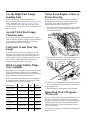
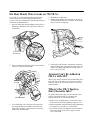
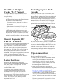
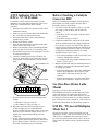
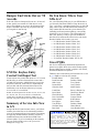
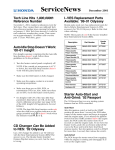
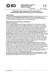
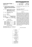
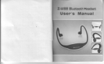
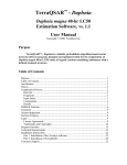
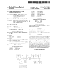
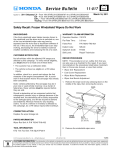
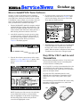
October 98 How to Install PGM Tester Software We know, we know. S/Bs and S/N articles constantly remind you to have the latest software version loaded in your PGM Tester, but they don’t describe how to install it. Installation is pretty simple; you just need to know the basics of the DCS (Dealer Communication System). Grab your PGM Tester, and follow these steps: 4. To select the latest version, move the cursor to the bottom of the screen and click on Complete. Then you’ll see this display with a picture of the PGM Tester and some additional steps: 1. Find the HONDANET 2000 DCS computer terminal with the PGM Tester update cable attached to it. The cable has an adapter plug that connects it to the back of the terminal. Some of the latest cables also have a label showing which end connects to the Tester. 2. At the DCS terminal, log into the system by typing your dealer number, operator ID, and password. If you don’t know these numbers, ask your service or parts manager for them. When you click on Complete, this display appears: 5. With PGM Tester in hand, make sure the 4MB PGM Card (P/N 02002181) is installed in it, and follow the steps on the screen to complete the software update. When the update is completed (it takes about 10 minutes), the screen above will appear again. 3. From the list of choices across the top of the screen, click on Service Bay, and PGM Tester appears. Then click on Update PGM Card, and you’ll see this display: Easy ID for CR-V and Accord Transmitters Keyless remote transmitters used on ’97-98 CR-Vs and ’98 Accords look similar, but aren’t interchangeable. Use the info below to identify them. On ’97-98 CR-Vs, security system transmitters have the word OPTION on the Option button. Transmitters for CR-Vs with keyless entry systems have an “open trunk” picture on the Option button. On ’98 Accord LXs, transmitters have the word OPTION on the Option button. Transmitters for EX models have an “open trunk” picture on the option button. To avoid mixing up Accord EX and CR-V keyless entry transmitters, turn the transmitters over, and use this illustration to identify them: ACCORD EX CR-V NOTE: Near the top of the screen is a list with three or more PGM Tester software versions with the latest one highlighted. At the bottom is application info describing which vehicles and systems are covered in the highlighted version. Use the Right Fuel Gauge Sending Unit Noises From Engine, Trans, or Power Steering If you need to replace the fuel sending unit on a ’98 Accord as described in S/B 98-056, Inaccurate Fuel Gauge, make sure you install the new and improved unit. To identify the new unit, look at the wires going into its connector; if one of the wires is solid yellow, you have a new unit. On the ’98 Accord V6, various grinding, moaning, or clicking noises heard with the engine running can be resolved by “bird caging” the end of the right side engine ground wire. Here’s how to do it: 1. Remove the bolt from the terminal end of the ground wire. The wire is near the right inner fender on the front of the strut tower. Accord V6/L4 Fuel Gauge Characteristics On the ’98 Accord V6, the fuel gauge drops to empty when you turn the ignition switch off. On L4 models, the gauge retains its reading with the key off. These are normal characteristics for both models. ENGINE GROUND WIRE Cold Start Crank Time Too Long? A low fuel level can cause a long crank time at cold start-up on ’96-98 Civics. To test the crank time, use a stopwatch or the PGM Tester, and make sure the fuel tank is at least 1/2 full. A cold start crank time of up to two seconds is normal. With the fuel tank close to empty, the crank time will be even longer. 2. Insert a small screwdriver into the terminal end, and twist the wire until the strands become parallel. Untwist the wire strands. Oil & Coolant Gallery Plugs Now Available On Accords, Civics, and Odysseys, most oil and coolant gallery plug bolts and washers are now available as separate parts. If you need to replace (or just tighten) the plugs, find what you need in the chart below. NOTE: The 28 mm head sealing bolt isn’t available yet. If you have one that’s leaking, try replacing its washer and retightening it to 105 N⋅m (76 lb-ft). Description P/N H/C Torque Head Sealing Bolt, 28 mm – – 105 N⋅m (76 lb-ft) 12207-634-300 1119924 – Washer, 28 mm Block Sealing Bolt, 16 mm 11106-PT0-300 4769659 40 N⋅m (29 lb-ft) Washer, 16 mm 12207-PC6-300 2508059 – Block Sealing Bolt, 20 mm 15233-PK1-000 2622371 55 N⋅m (40 lb-ft) 94109-20000 0251728 – 12208-PG6-300 2661114 17 N⋅m (12 lb-ft) Washer, 20 mm Head Sealing Screw ‘‘Bird cage” the wire. 3. Hold the wire, and push the terminal end toward it so the wire strands bulge into the shape of a bird cage. 4. Reinstall the wire. 5. Run the engine to verify that the noises are gone. HomeLink Won’t Program: ’98 Accord If you can’t program the HomeLink transmitter on a ’98 Accord, you may need to erase the factory test data in the system’s memory. To do this, press and hold the two outside buttons on the HomeLink transmitter until the LED starts to blink. You may need to hold the buttons for up to 30 seconds. If you still can’t program the transmitter, call HomeLink at 800-355-3515. Fix Rear Hatch Water Leaks on ’98 CR-Vs On ’98 CR-Vs, a water leak from the rear hatch glass can be caused by the hatch hinges pinching the top corners of the rear weatherstrip. Follow this procedure to confirm the problem and fix it: 4. Reinstall the weatherstrip. 5. Sitting on the tailgate, move the glass to its closed position and make sure the top corners of the hinges don’t touch the weatherstrip. 1. Open the hatch glass and the tailgate, then look for a flattening or distortion at the top corners of the rear weatherstrip. Look for weatherstrip distortion here. 2. If the weatherstrip is distorted, pull it away from the corners to expose the body flange. 6. If the hinges still touch the weatherstrip, loosen the hinge mounting nuts, and adjust the hatch rearward about 2 mm. Hatch adjustment is on page 20-81 of the ’97-98 CR-V S/M. Armrest Can’t Be Added on CR-Vs with M/T BODY FLANGE Since it may interfere with the floor-mounted shift lever, there’s no way to add a driver’s seat armrest on CR-Vs with M/T. In fact, the seat frame doesn’t even have an armrest bracket. Where’s the CR-V Keyless Entry/Security Info? WEATHERSTRIP 3. Cover the flange with a shop towel, then bend the area under the distortion slightly downward with pliers. This will allow some clearance between the weatherstrip and the hinges. To quickly find keyless entry, remote transmitter, and security system info on CR-Vs, use these page references from the ’97-98 S/M and ETM: • Keyless entry troubleshooting is in the Power Door Lock section of the S/M, beginning on page 23-123. • Remote transmitter troubleshooting and programming are on pages 23-130 and 23-131 of the S/M. • For security system wire diagrams and a description of how the system works, refer to pages 133 thru 133-7 of the ETM. Rear Wheel ABS Quick Checks: ’94–97 Passport No Ceiling Light on ’90–98 Accords To diagnose ABS DTC 9 (high resistance in speed sensor) on a ’94–97 Passport with rear ABS, do these two quick checks: On any ’90–97 Accord or ’98 Accord DX/LX, if the ceiling light doesn’t work when you open the doors even though the safety indicator shows the doors opening and closing correctly, the safety indicator’s printed circuit board may be damaged. To check the board, remove the gauge assembly, and ground the BLK/WHT wire in the safety connector’s 14P connector. If the ceiling light comes on when the wire is grounded, the safety indicator printed circuit board is damaged and must be replaced. 1. Unplug the 2P connector from the speed sensor on the differential, and measure the resistance between the connector’s WHT and BLK wires. • If the resistance is more than 2.5 kΩ, replace the sensor, clear the DTC, and return the vehicle to the customer. • If the resistance is less than 2.5 kΩ, plug in the GAUGE ASSEMBLY speed sensor connector, and go to step 2. 2. Unplug the connector from the rear-wheel ABS control module (under the front passenger’s seat), and measure the resistance between the connector’s BLU and YEL wires. If the resistance is more than 2.5 kΩ, there’s an open circuit between the control unit and the speed sensor. Plug in the connector, then look for (and repair) the open circuit. Shortcut Diagnosing DTC P1607 on ’98 Accords To diagnose DTC P1607 (ECM/PCM internal failure) on a ’98 Accord, you need to do the troubleshooting on page 11-80 of the ’98–99 Accord S/M. During the procedure, when it asks you to install a known-good ECM/PCM, save yourself some time by using the new shortcut on page 11-5. If the DTC goes away when the known-good ECM/PCM is connected, replace the original ECM/PCM. And when you replace the ECM/PCM, don’t forget to reprogram the new one to the vehicle keys. Reprogramming is in S/B 98-024, ECM/PCM Replacement and Substitution, filed under Body Electrical. Leather Seat Noise On vehicles with leather seating surfaces, the leather-to-leather contact can cause what sounds like a rattle when you drive over rough roads. The noise usually happens because of contact between the seat-back and the cushion. To confirm the cause, change the position of the seat-back: the noise will be worse when it’s fully forward and get more quiet when it’s reclined. To eliminate the noise, apply a light film of liquid dishwashing soap (such as Dawn) to the contact surfaces with a clean finger or shop towel, and wipe off the excess. Don’t use a lot of soap, and keep it off the seating surfaces. Pass this tip on to your customers; they might want to use it too. BLK/WHT WIRE So what causes the board to go bad? It’s usually because of an aftermarket security system. Many of these systems use the safety indicator’s BLK/WHT wire (also the main wire for the ceiling light circuit) to indicate when the doors are open. If the wire can’t handle the amperage requirements of the aftermarket system, the circuit board gets damaged, and the ceiling light won’t work. Tips on Immobilizer Here are three tips to use when you work on a ’97–98 Prelude’s immobilizer control unit: • To get keys that will match the immobilizer control unit if all the vehicle’s keys are lost or stolen, you need to replace the immobilizer control unit and program it to the vehicle. New control units come with a black master key, a gray valet key, and a red learning key. The new keys need to be cut to match the vehicle’s ignition switch and locks. • When using the PGM Tester to program a new immobilizer control unit, the Tester will prompt you to do several operations with the “original” keys. The keys that come with the new control unit are considered original keys. If any keys from the vehicle are still available, the Tester considers them to be “new” keys. To avoid confusion between original and new keys, tag the keys that come with the new control unit. • To program a new immobilizer control unit, refer to S/B 96-051, Information on the Immobilizer System, filed under Electrical in your S/B binder. ATTS Indicator On & No DTCs: ’97–98 Prelude Before Checking a Catalytic Converter DTC If a Prelude’s ATTS (active torque transfer system) indicator is on but the PGM Tester doesn’t retrieve any ATTS DTCs, troubleshoot the ATTS with this procedure: 1. Disconnect the PGM Tester from the vehicle’s DLC (data link connector). 2. Make sure you have the anti-theft code for the radio, then write down the radio station presets. 3. Disconnect both battery cables, then hold them together for 15 seconds. 4. Reconnect the battery cables. 5. Enter the anti-theft code for the radio and the radio station presets, then set the clock. 6. Remove the passenger’s door sill molding and kick panel (see page 20-41 of the ’97-99 Prelude S/M). 7. Peel back the carpet in the front passenger’s footwell to expose the ECM cover. 8. Connect a voltmeter between the YEL/BLU wire (cavity 26) of the ATTS control 26P connector and body ground. The 26P connector is the one on the right. Before you troubleshoot an OBD II vehicle that stores DTC P0420 (67) (catalyst system efficiency below threshold), run these quick checks: ATTS CONTROL UNIT ECM COVER YEL/BLU WIRE 9. Turn the ignition switch on and read the reference voltage. • If less than 5 volts, go to step 10. • If the reading is 5 volts, go to step 11. 10. Disconnect the connectors for the left pressure switch, the right pressure switch, the lateral G-sensor, and the steering angle sensor one at a time until you see the reference voltage increase to 5 V. Replace the component that held the reference voltage low. 11. Do the ATTS function test and the steering angle neutral position memorization shown in S/B 97-023, Service Manual Update: ATTS Service Procedures, filed under Transmission in your S/B binder. 1. Check for a leak in the exhaust system. If you find one, repair it, clear the DTC, and test-drive the vehicle. • If the DTC doesn’t come back, return the vehicle to the customer. • If the DTC returns, go to step 2. 2. Connect the PGM Tester, and test-drive the vehicle while an assistant monitors the voltage signal from the secondary oxygen sensor (HO2S S2). After the catalyst reaches operating temperature, the HO2S S2 voltage should stay between 0.5 and 0.8 V at steady cruising speed. During deceleration, the voltage should be steady at 0.1 V or less. • If the voltage readings are OK, clear the DTC, and return the vehicle to the customer. • At cruising speed, if the voltage fluctuates or stays below 5 V, go to step 3. 3. Measure the inlet and outlet external temperatures of the catalytic converter with a thermometer capable of reading up to 500°F. • If the outlet temperature is more than 100°F hotter than the inlet temperature, the converter is OK; clear the DTC, and return the vehicle to the customer. • If the outlet temperature is less than 100°F hotter than the inlet temperature, replace the converter. Use One-Piece Brake Lathe Mount In August, a one-piece speed mount (P/N KWI-10800300) for the on-car brake lathe was sent to your service manager. It replaces the old two-piece mount. The one-piece mount is much easier to use, and it’ll help you avoid comebacks on your disc refinishing jobs. For more info, see the August 25, 1998 revision of S/B 86-020, Honda Brake Disc Refinishing Guidelines. S/M Fix: ’98 Accord Multiplex Mode Test 2 On page 22-129 of the ’98-99 Accord S/M, cross out “Ignition key switch” in the list of circuits you can check with the driver’s multiplex control unit in the mode 2 test. Since the ignition switch must be ON to check any of the circuits, the control unit can’t check the ignition switch. Bumper End Sticks Out on ’98 Accords Do You Know Where Your S/Bs Are? If the end of the rear bumper sticks out on a ’98 Accord 4-door, push it in to reattach it. If this doesn’t work, remove the taillight so you can see the alignment of the bumper end and its clip. Then as you push on the end, you can guide it onto the clip. Are your S/Bs neatly filed away in your S/B binders so you can easily find them? While we hope the answer is “Yes,’’ we know it’s sometimes hard to keep up with S/B filing. That’s where the S/B bound books can help you. They contain all S/Bs issued in a given calendar year (including recalls and product updates), conveniently organized by service category. The S/B bound books aren’t free, but they’re easy to get. Just call Helm at 800-782-4356, and from the choices below, ask for the Reorder Number of the book(s) you need. HOLDING CLIP BUMPER END • • • • • • • • ’97 S/Bs, Reorder Number Y0504, $20. ’96 S/Bs, Reorder Number Y0461, $15. ’95 S/Bs, Reorder Number Y0434, $20. ’94 S/Bs, Reorder Number Y0413, $15. ’93 S/Bs, Reorder Number Y0381, $15. ’92 S/Bs, Reorder Number Y0380, $15. ’91 S/Bs, Reorder Number Y0379, $15. ’74-’90 S/Bs, Reorder Number Y0378, $35. Great PQRs S/M Fix: Keyless Entry Control Unit Input Test To test keyless entry control unit inputs on a ’97 Accord, half the time you need to disconnect the control unit’s 12P and 18P connectors, and half the time you need to keep them connected. In the S/M, it’s implied that all tests are done with the connectors disconnected. For clarification, write in this note below step 3 on page 23-312 of the ’97 Accord S/M: NOTE: To do an input test on cavities A1, A2, A3, A5, A6, A7, A8, A9, A11, A12, A15, and A17, reconnect the control unit’s 12P and 18P connectors. Make sure you insert the wire probe from the wire side of the connectors. Summary of Service Info Now in S/N Along with this S/N (and in future issues), you’ll find a summary sheet that lists service information mailed to your service manager the previous month. The summary will typically include bulletins, manuals, newsletters, installation instructions, and the latest PGM Tester software update. If you see something on the summary that you need but didn’t receive, ask your service manager for a copy of it. Our Service Engineering Information Department is pleased to recognize those who send in Product Quality Reports (PQRs) that are legible, complete, well-written, and include illustrations or photos. Thanks to these conscientious professionals who’ve sent in great PQRs over the last few months. Kordell Balster Darin Bowman Mike Curtis Donna Gillis Nicholas Giusti Linda Hans Ryan Hatch David Holshey Dave Lauderdale Robert Martel Jim Updyke Tony Weikel Sherman Wong Ben Zatek Harr Honda Faulkner Honda Tracy Honda Casey Honda Marin Honda Brown’s Honda City John Elway Honda Fairfax Honda Lompoc Honda Kolbe Motors Bob’s Honda Faulkner Honda Hansel Honda Carrs Honda Center 1998 American Honda Motor Co., Inc. - All Rights Reserved. Published by AHM Service Publications, 1919 Torrance Blvd., Torrance, CA 90501-2746. All suggestions become the property of American Honda Motor Co., Inc.; sending a suggestion gives American Honda permission to publish it without further consideration. ASN 20153 (9810)