1
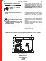
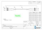
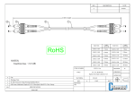
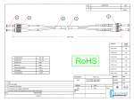
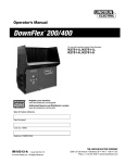
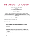
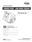
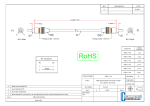
SVM1XX-A
View Safety Info
Return to Master TOC
RETURN TO MAIN INDEX
X, 2009
POWERWAVE C300
For use with machine code number:
111XX
Return to Master TOC
View Safety Info
Return to Master TOC
View Safety Info
Safety Depends on You
Lincoln arc welding and cutting
equipment is designed and built
with safety in mind. However,
your overall safety can be
increased by proper installation
. . . and thoughtful operation on
your part. DO NOT INSTALL,
OPERATE OR REPAIR THIS
EQUIPMENT WITHOUT READING THIS MANUAL AND THE
SAFETY PRECAUTIONS CONTAINED THROUGHOUT. And,
most importantly, think before you
act and be careful.
View Safety Info
Return to Master TOC
SERVICE MANUAL
Copyright © Lincoln Global Inc.
• World's Leader in Welding and Cutting Products •
• Sales and Service through Subsidiaries and Distributors Worldwide •
Cleveland, Ohio 44117-1199 U.S.A. TEL: 216.481.8100 FAX: 216.486.1751 WEB SITE: www.lincolnelectric.com
INSTALLATION
Return to Master TOC
Return to Master TOC
Return to Section TOC
Return to Section TOC
2
SHIELDING GAS CONNECTION
WARNING
CYLINDER may explode if
damaged.
• Keep cylinder upright and
chained to support.
• Keep cylinder away from areas where it may be
damaged.
• Never lift welder with cylinder attached.
• Never allow welding electrode to touch cylinder.
• Keep cylinder away from welding or other live
electrical circuits.
• BUILD UP OF SHIELDING GAS MAY
HARM HEALTH OR KILL.
• Shut off shielding gas supply when not in
use.
• See American National Standard Z-49.1, "Safety
in Welding and Cutting” Published by the
American Welding Society.
-----------------------------------------------------------------------MAXIMUM INLET PRESSURE IS 100 PSI. (6.9 BAR.)
Install the shielding gas supply as follows:
1. Secure the cylinder to prevent it from falling.
2. Remove the cylinder cap. Inspect the cylinder valves
and regulator for damaged threads, dirt, dust, oil or
grease. Remove dust and dirt with a clean cloth. DO
NOT ATTACH THE REGULATOR IF OIL, GREASE OR
DAMAGE IS PRESENT! Inform your gas supplier of
this condition. Oil or grease in the presence of high
pressure oxygen is explosive.
3. Stand to one side away from the outlet and open the
cylinder valve for an instant. This blows away any dust
or dirt which may have accumulated in the valve outlet.
4. Attach the flow regulator to the cylinder valve and tighten the union nut(s) securely with a wrench. Note: if
connecting to 100% CO2 cylinder, insert regulator
adapter between regulator and cylinder valve. If
adapter is equipped with a plastic washer, be sure it is
seated for connection to the CO2 cylinder.
5. Attach one end of the inlet hose to the outlet fitting of
the flow regulator. Attach the other end to the welding
system shielding gas inlet. Tighten the union nuts with
a wrench.
6. Before opening the cylinder valve, turn the regulator
adjusting knob counterclockwise until the adjusting
spring pressure is released.
7. Standing to one side, open the cylinder valve slowly a
fraction of a turn. When the cylinder pressure gage
stops moving, open the valve fully.
8. The flow regulator is adjustable. Adjust it to the flow rate
recommended for the procedure and process being
used before making a weld.
POWER WAVE® C300’s internal gas connection should be connected to wire drive’s gas connection.
Return to Section TOC
Return to Master TOC
Return to Master TOC
FIGURE A.4
Return to Section TOC
2
ENTERNAL GAS
CONNECTION FOR
GMAW PROCESS
POWERWAVE C300
INSTALLATION
Return to Master TOC
Return to Section TOC
3
TIG WELDING
3
SMAW WELDING
(Figure A.7)
Tig uses Electrode Negative Polarity so for this application, connect the Tig torch to the negative (-) output
stud and connect the work clamp to the positive (+)
output stud. The TIG torches gas connection should be
connected to the POWER WAVE® C300’s internal gas
supply connection. If required a foot amptrol can be
connected to the remote control receptacle.
Most SMAW welding procedures use Electrode
Positive welding. For these applications, connect the
stick electrode holder to the positive (+) output stud
and connect the work clamp to the negative (-) output
stud.
Some SMAW welding procedures does use Electrode
Negative Polarity. For these applications, connect the
stick electrode holder to the negative (-) output stud
and connect the work clamp to the positive (+) output
stud.
Return to Master TOC
Return to Section TOC
FIGURE A.7
SPOOL GUN /
PUSH PULL
RECEPTACLE
REMOTE CONTROL
RECEPTACLE
POSITIVE
STUD (+)
Return to Master TOC
Return to Section TOC
GAS SUPPLY
CONNECTION
NEGATIVE
STUD (-)
TO POSITIVE
STUD (+)
WORK CLAMP
WORK PIECE
TO NEGATIVE
STUD (-)
Return to Master TOC
Return to Section TOC
POWER CABLE
TO GAS SUPPLY
CONNECTION
TIG TORCH
GAS HOSE
TO REMOTE CONTROL
RECEPTACLE
FOOT AMPTROL
(OPTIONAL)
POWERWAVE C300
OPERATION
Return to Master TOC
Return to Section TOC
4
4
CASE FRONT CONTROLS
(Code 11479)
FIGURE B.1
1
2
Return to Master TOC
Return to Master TOC
Return to Master TOC
Return to Section TOC
Return to Section TOC
Return to Section TOC
3
4
10
5
11
6
12
7
13
8
14
15
9
All operator controls and adjustments are located on
the case front of the Power Wave. (See Figure B.1)
9. ON/OFF SWITCH- Controls power to the Power
Wave® C300.
1. LEFT DISPLAY- Shows wire feed speed or amperage,
10. RIGHT DISPLAY- Shows voltage or trim.
2. LEFT KNOB- Adjusts value in left display.
11. THERMAL LIGHT- Indicates when machine has
thermal fault.
12. RIGHT KNOB- Adjusts value in right display.
3. MAIN DISPLAY- Shows detailed welding and diagnostic information.
13. SET-UP- Lights when machine is in set-up mode,
4. LEFT BUTTON- Changes the Main display to show
the Weld Mode or Arc Control.
14. IR PORT- Used to transfer information to palm
computers, etc.
5. MAIN KNOB- Changes the values on the Main display.
15. RIGHT BUTTON- Used to toggle start options and
to end options.
6. PROCEDURE BUTTON- Selects A or B procedure,
or gun control.
7. 2-STEP/4-STEP BUTTON- Toggles between 2-step
and 4-step trigger operation.
8. MEMORIES BUTTONS- For selection of common
procedures.
POWERWAVE C300
Return to Section TOC
Return to Master TOC
Return to Section TOC
Return to Master TOC
Return to Section TOC
Return to Master TOC
Return to Master TOC
Return to Section TOC
5
OPERATION
CASE BACK CONTROLS
(Code 11479)
FIGURE B.2
1
2
3
1. ETHERNET CONNECTOR
2. GAS CONNECTION
3. POWER CORD
POWERWAVE C300
5
OPERATION
Return to Master TOC
Return to Master TOC
Return to Section TOC
Return to Section TOC
6
INTERNAL CONTROLS
(Code 11479)
FIGURE B.3
2
4
5
6
7
Return to Master TOC
9
10
11
12
1. SPINDLE BRAKE
7. POSITIVE STUD
2. WIRE DRIVE PRESSURE ARM
8. GAS CONNECTION
3. THUMB SCREW, FOR SECURING THE WELDING GUN
9. NEGATIVE STUD
4. GUN BUSHING
10. COLD INCH / GAS PURGE SWITCH
5. SOCKET HEAD CAP SCREW FOR SECURING
THE GUN BUSHING
11. 6-PIN CONNECTOR FOR REMOTE CONTROL
OPTIONS
6. 4-PIN TRIGGER RECEPTACLE
12. 7-PIN CONNECTOR FOR PUSH / PULL OR
SPOOL GUN OPTIONS
Return to Master TOC
Return to Section TOC
1
3
8
Return to Section TOC
6
POWERWAVE C300
OPERATION
Return to Master TOC
Return to Section TOC
7
7
CASE FRONT CONTROLS USED
WIRE FEED SPEED (WFS)
AMPS
+
LESS
AMPS
+
MORE
AMPS
OUTPUT
OFF
VOLTS
TRIM
OUTPUT
ON
Return to Section TOC
Return to Master TOC
Return to Master TOC
Return to Master TOC
IR PORT
Return to Section TOC
Return to Section TOC
SETUP
WELD MODE
START OPTIONS
UltimArc™ Control
END OPTIONS
DUAL PROCEDURE/
MEMORY PANEL OPERATION
POWERWAVE C300
OPERATION
Return to Master TOC
Return to Section TOC
8
ALUMINUM SYNERGIC GMAW-P
(PULSED
MIG)AND
GMAW-PP
(PULSE ON PULSE) WELDING
The Power Wave® C300 can produce top quality aluminum welds with excellent appearance, little spatter
and good bead shape. Push-pull guns are available
for consistent feeding when welding a long distance
away from the wire feeder.
Return to Master TOC
Return to Section TOC
PULSE-ON-PULSE WELDING
The Power Wave system offers both traditional pulse
and Pulse-on-Pulse™. Pulse-on-Pulse (GMAW-PP) is
an exclusive waveform for aluminum welding. Use it to
make welds with a "stacked dime" appearance, similar
to GTAW welds.( See Figure B.7)
FIGURE B.7
8
ALUMINUM GMAW-P AND GMAW-PP
ALUMINUM PULSE WELDING
Synergic GMAW-P (Pulsed MIG) welding is ideal for
low spatter, out of position and reduced heat input
applications. During pulse welding, the welding current
continuously switches from a low level to a high level
and then back again. Each pulse sends a small droplet
of molten metal from the wire to the weld puddle.
Pulse welding controls the arc length with 'Trim'
instead of voltage. When trim (arc length) is adjusted,
the Power Wave automatically recalculates the voltage,
current and time of each part of the pulse waveform for
the best result. Trim adjusts the arc length and ranges
from 0.50 to 1.50, with a nominal value of 1.00 for a
3/4" (19mm) electrode stick-out. Trim values greater
than 1.00 increase the arc length, while values less
than 1.00 decrease the arc length.
(See Figure B.10)
FIGURE B.10
Return to Master TOC
Return to Section TOC
The pulsing frequency is adjustable. Changing the frequency modulation (or arc control) of the waveform
changes the ripple spacing. Faster travel speeds may
be achieved by using higher values of frequency modulation. ( See Figure B.8 and B.9p)
Trim .50
Arc Length Short
FIGURE B.8
Frequency Modulation = -10
Wide weld and ripple spacing, slow travel speed.
Return to Master TOC
Return to Section TOC
FIGURE B.9
Frequency Modulation = 10
Narrow weld and ripple spacing, fast travel speed.
POWERWAVE C300
Trim 1.00
Arc Length Medium
Trim 1.50
Arc L ength Long
OPERATION
Return to Master TOC
Return to Section TOC
9
If the passcode does not equal zero (0000), enter the
passcode now. If the passcode has been forgotten, a p.c.
computer application or Palm O.S. application is required
to change the passcode.
Memory Value
Low Limit
200
High Limit
9
The memory value must always be less than or equal
to the high limit, and greater than or equal to the low
limit.
After setting limits, press the memory button with the
flashing LED. The MSP4 will ask to save or discard the
limit changes just made. Press the left MSP4 for button (YES) to save and enable the limits and exit. Press
the right MSP4 button (NO) to exit and leave limits
unchanged.
SETUP
HI = 200
LO = 180
WELD WFS
IR PORT
Enabling/Disabling Limits
START OPTIONS
WELD MODE
UltimArc™ Control
Enable/Disable
Limits: Press
10 seconds
END OPTIONS
Return to Master TOC
Return to Master TOC
Return to Section TOC
Return to Section TOC
Parameter Name
A
If the passcode has been set to zero (0000), SETUP will
illuminate on the MSP4 panel and the display will show
the following:
Four items show on the MSP4 panel.
• Memory Value
• High Limit
• Low Limit
• Parameter Name
One of these items will flash to indicate which item will
change when the MSP4 encoder is rotated. Press the
right button on the MSP4 panel to select the item to
change.
200
Return to Master TOC
IR PORT
M
M
1
2
3
4
5
6
7
8
Limits for each memory may be enabled or disabled
by pressing and hold the appropriate memory button
for 10 seconds. Release the memory button when
the MSP4 display shows the following:
MEMORY 2 LIMITS
ENABLE / DISABLE
SETUP
HI = 200
LO = 180
WELD WFS
SETUP
IR PORT
START OPTIONS
WELD MODE
UltimArc™ Control
END OPTIONS
START OPTIONS
WELD MODE
UltimArc™ Control
END OPTIONS
If the passcode does not equal zero, enter the passcode
now. If the passcode is zero (0000), SETUP will light
and the MSP4 displays the following:
Rotate to
Change
Value.
Return to Section TOC
GUN B
Press to
select item
to change.
The Limits Setup menu shows a list of all parameters
available for the weld mode stored in the memory chosen. For example, if limits are being set for a stick
(SMAW) mode, parameters such as Run-in WFS and
Postflow will not appear.
To lock a parameter to a specific value that cannot
be changed, set the high and low limits to the
same value.
ENABLE LIMITS?
Yes
No
WELD MODE
UltimArc™ Control
SETUP
IR PORT
START OPTIONS
END OPTIONS
Press the left MSP4 button (YES) to enable limits or
the right MSP4 button (NO) to disable limits. Disabling
limits does not change any limits values that may
have been previously set.
POWERWAVE C300