1
To buy, sell, rent or trade-in this product please click on the link below:
http://www.avionteq.com/Howell-Instruments-H337NP-107-Engine-Test-Set-Analyzer.aspx
www.avionteq.com
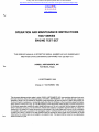
OPERATION AND MAINTENANCE INSTRUCTIONS
H337 SERIES
ENGINE TEST SET
THIS SERVICE MANUAL IS EFFECTIVE SERIAL NUMBER 400 AND SUBSEQUENT
AND PRIOR UNITS CONTAINING SOFTWARE H101-228 REV 4.01
HOWELL INSTRUMENTS, INC.
Fort Worth, Texas
15 SEPTEMBER 1988
Change 4: 7 NOVEMBER, 1994
This document discloses subject matter in which HOWELL INSTRUMENTS, INC. has proprietary rights and such subject matter shall not, without the written permission of HOWELL INSTRUMENTS, INC., be either (a) used, released or
disclosed in whole or in part outside any Company or the Government, (b) used in whole or in part by the Company or
the Government for manufacture or (c) used by a party other than the Company or the Government except for (I) emergency repair or overhaul work only, by or for the Company or the Government, where the item or process concerned is
not otherwise reasonably available to enable timely performance of the work, provided that the release or disclosure
hereof outside the Company or the Government, shall be made subject to a prohibition against further use, release, or
disclosure; or (ii) release to a foreign government, as the interest of the United States may require, only for information
or evaluation within such government or for emergency repair or overhaul work by or for such government under the
conditions of (I) above. Therefore, the data contained herein is restricted to "limited rights" and is proprietary to Howell
Instruments, Inc. Limited rights are not subject to an expiration date. This legend shall be marked on any reproduction
hereof in whole or in part.
1
1
1
1
1
1
1
1
1
1
1
11
11
11
1
1
1
1
1
1
1
1
1
1
1
1
1
1
1
1
1
1
1
1
1
1
1
1
1
1
1
1
1
1
1
1
1
1
1
1
1
1
1
1
1
1
1
1
1
1
1
1
1
1
1
1
1
1
1
1
1
1
1
1
1
1
1
1
1
1
1
1
1
THIS DOCUMENT IS SUBJECT TO THE LEGEND
RESTRICTIONS ON THE TITLE PAGE
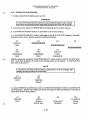
RECORD OF CHANGES
OPERATION AND MAINTENANCE INSTRUCTIONS
H337N SERIES
ENGINE TEST SET
Date of Original Issue: 15 September 1988
Instructions for updating manual: Remove old pages and replace with new pages having latest
change number. Latest changes are indicated by change bars in the margins.
Page
No.
Change.
No.
A
iv
5-31
6-11
6-13
7-3 -7-8A
7-9 - 7-12
7-15 - 7-16
7-19
7-21
7-24
7-26 -7-28A
7-30
7-32 - 7-36A
7-38
7-41 - 7-43
7-46
7-48 -7-50
7-54
7-56 - 7-61
Title
A
iv
1-1
3-1
4-12
8-1
Title
3-2
4-18
1
1
1
1
1
1
1
1
1
1
1
1
1
1
1
1
1
1
1
1
2
2
2
2
2
2
2
3
3
3
A
Date
10-16-90
10-16-90
10-16-90
10~16-90
10-16-90
10-16-90
10-16-90
10-16-90
10-16-90
10-16-90
10-16-90
10-16-90
10-16-90
10-16-90
10-16-90
10-16-90
10-16-90
10-16-90
10-16-90
10-16-90
9-27-91
9-27-91
9-27-91
9-27-91
9-27-91
9-27-91
9-27-91
6-6-94
6-6-94
6-6-94
Page
No.
Change
No.
Date
Title
A
i
3-1 - 3-4
4-17 - 4-188
7-4
7-6
7-15
7-38
4
4
4
4
4
4
4
4
4
11-7-94
11-7-94
11-7-94
11-7-94
11-7-94
11-7-94
11-7-94
11-7-94
11-7-94
Change 4
I
II
I
II
I
THIS DOCUMENT IS SUBJECT TO THE LEGEND
RESTRICTIONS ON THE TITLE PAGE
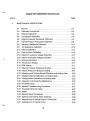
TABLE OF CONTENTS
Section
Page
INTRODUCTION AND GENERAL INFORMATION
II
1-1
1-2
1-3
1-4
1-5
Introduction
General
Purpose
Scope
Arrangement.
1-6
1-7
Abbreviations and Symbols
General Equipment Information
1-1
1-3
1-8
1-9
1-10
Functions of Tester
Specifications
Physical Description
1-3
1-4
1,-6
SPECIAL TOOLS AND TEST EQUIPMENT
2-1
III
Special Tools and Test Equipment List..
2-1
PREPARATION FOR USE AND SHIPMENT
3-1
3-2
3-3
3-4
3-5
3-6
3-7
3-8
IV
·
1-1
1-1
1-1
1-1
1-1
Preparation for Use
Unpacking
Engine Test Setups
Loading Internal Printer Paper In Printer MAP-20SBCL.
Loading Internal Printer Paper in Printer MAP-21CBC
Cable for Optional External Printer
Setting External Printer Baud Rate
Preparation for Shipment
3-1
3-1
3-1
3-1
3-2
3-2 .
3-3
3-4
OPERATION INSTRUCTIONS
4-1
Theory of Operation
.4-1
Change 4
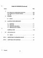
TABLE OF CONTENTS (Continued)
Page
Section
IV
4-2
General............................................ 4-1
4-3
Computer System . . . . . . . . . . . . . . . . . . . . . . . . . . . . . . . . . . . . 4-1
4-6
Engine Temperature Measuring Circuit
4-3
4-8
Ambient Temperature Measuring Circuit
4-3
4-9
Insulation Resistance Measuring Circuit . . . . . . . . . . . . . . . . . . . 4-5
4-10 Engine TC Resistance Measuring Circuit
4-5
4-11 Aircraft Instrument Resistance Set Circuit . . . . . . . . . . . . . . . . . . 4-5
4-12 Aircraft Indicator Check Circuit . . . . . . . . . . . . . . . . . . . . .. . . . . 4-6
4-13 RPM Measuring Circuit . . . . . . . . . . . . . . . . . . . . . . . . . . . . . . . . 4-6
4-14 Pressure Measuring Circuit
4-6
4-15 Display Circuit . . . . . . . . . . . . . . . . . . . . . . . . . . . . . . . . . . . . . . . 4-6
4-16 Power Supply
4-6·
4-17 Operation Instructions
4-12
:................ 4-12
4-18 Indicators and Controls
4-19 Power Up Procedure
4-20 Setting Identification and Trim Target Numbers
4-19
4-20
4-21 Setting PAMB
4-21
4-22 Setting TAMB
4-22
4-23 Aircraft Temperature Indicator Calibration
4-22
4-24 D'Arsonvallndicators
4-22
4-25 Null Balance Indicators . . . . . . . . . . . . . . . . . . . . . . . . . . . . . . . . 4-22
4-26 Aircraft Circuit Resistance Adjustment (D'Arsonvallndicators) .. 4-23
4-27 Aircraft Thermocouple System Insulation Resistance Check ... 4-23
4-28 Engine Trim Check Operation . . . . . . . . . . . . . . . . . . . . . . . . . .. 4-24
4-29 Turbojet Engine Trim Check
'. 4-24
4-30 Turboprop Engine Trim Check . . . . . . . . . . . . . . . . . . . . . . . . . . 4-25
4-31 Displaying and Printing Data
4-25
4-32 Displaying Data . . . . . . . . . . . . . . . . . . . . . . . . . . . . . . . . . . . . . . 4-26
4-33 Printing Data . . . . . . . . . . . . . . . . . . . . . . . . . . . . . . . . . . . . . . .. 4-26
ii
TABLE OF CONTENTS (Continued)
Section
V
Page
MAINTENANCE INSTRUCTIONS
5-1
5-3
5-4
5-5
5-6
5-7
5-8
5-9
5-10
5-11
5-12
5-13
5-14
5-15
5-16
5-17
5-18
5-19
5-21
5-22
5-23
5-25
5-26
5-27
5-28
5-29
5-30
5-31
5-32
General
,
5-1
Calibration Instructions
5-2
External Calibration ...................................5-2
Temperature Calibration
5-2
External Pressure Transducer Calibration
5-5
Internal Pressure Transducer Calibration
5-8
Insulation Resistance Calibration
5-11
TIC Resistance Calibration
5-12
Internal Calibration
5-12
Cold Junction Calibration
5-13
External Transducer Voltage Calibration
5-14
Internal Transducer Voltage Calibration
5-15
Scaling Instructions
5-16
Temperature Scaling
5-16 .
RPM Scaling
5-17
External Pressure Transducer Scaling
5-18
Internal Pressure Transducer Scaling
5-21
Displaying and Printing Stored Calibration and Scaling Data
5-22
Displaying Stored Calibration and Scaling Data
5-22
Printing Stored Calibration and Scaling Data
5-25
Inspection and Preventive Maintenance
5-25
Troubleshooting
5-27
General Troubleshooting Procedures
5-27
Troubleshooting the Tester
5-27
Repair
5-29
General Repair Procedures
5-29
Opening and. Closing Tester Assembly
5-29
Replacement of Internal Pressure Transducer
5-30
Replacement of Internal Printer
5-30
iii
TABLE OF CONTENTS (Continued)
Page
Section
v
5-33 Replacement of Display Board Components .....•......... 5-30
5-34 Replacement of Pushbutton Switches. . . . . . . . . . . . . . . . . . . .. 5-31
5-35 Test. . . . . . . . . . . . . . . . . . . . . . . . . . . . . . . . . . . . . . . . . . . . . . .. 5-31
VI
DIAGRAMS
6-1
VII
General. . . . . ,'. . . . . . . . . . . . . . . . . . . . . . . . . . . . . . . . • . • . . • 6-1
ILLUSTRATED PARTS BREAKDOWN
7-1
7-3
7·5
7-7
Introduction . . . • . • . • • • . • . • . . . . . . . . . . . . . . . . . . . . . . . . . . .
Parts Usted . . . . • • . • . . . . . . . . . . . . . • • . . . . . . . . . . . . . . . . ..
Symbols and Abbreviations ....................•......•
Maintenance Parts Ust (MPL)
7-1
7-1
7-1
7-1
NUMERICAL INDEX .................•....•....••......... 7-54
VIII
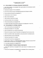
APPLICATION DATA
8-1
General ........•............................•.... ; . 8-1
APPX A
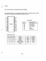
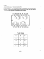
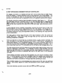
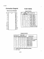
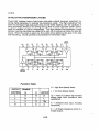
DESCRIPTIONS OF INTEGRATED CIRCUITS
A-1
APPX B
ACCEPTANCETEST PROCEDURE
B-1
Change 2
Iv
THIS DOCUMENT IS SUBJECT TO THE LEGEND
RESTRICTIONS ON THE TITLE PAGE
Notice:
Howell Instruments, Inc. no longer releases assembly drawings,
wiring schematics, Functional Descriptions, or illustrated parts
lists, except to authorized repair stations.
For repair or replacement, please contact:
Howell Instruments, Inc.
8945 South Freeway
Fort Worth, TX 76140
817-336-7411
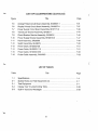
LIST OF ILLUSTRATIONS
Title
Figure
Page
1-1
H337N Series Engine Test Set
1-2
3-1
Loading Internal Printer Paper
3-1
3-2
External Printer Cable for RS232 Interface
3-2
3-3
External Printer Cable for Current Loop Interface
3-3
4-1
Computer System Block Diagram
.4-2
4-2
Engine Temperature Measuring Circuit, Simplified Schematic
.4-4
4-3
TAMB Measuring Circuit, Simplified Schematic
.4-4
4-4
4-5
Insulation Resistance Measuring Circuit, Simplified Schematic
.4-5
Thermocouple Resistance Measuring Circuit, Simplified Schematic .. .4-7
4-6
Aircraft Instrument Resistance Set Circuit, Simplified Schematic
.4-7
4-7
Aircraft Indicator Check Circuit, Simplified Schematic
.4-8
4-8
RPM Measuring Circuit, Simplified Schematic
.4-9
4-9
Pressure Measuring Circuit, Simplified Schematic
.4-10
4-10
4-11
Power Flow Block Diagram
Tester Indicators and Controls
.4-11
.4-12
4-12
5-1
Sample Printout of Stored Data
Thermocouple Input Calibration Setup
4-27
5-4
5-2
External Pressure Test Setup
5-7
5-3
Socket S104 Pin Identification
5-13
5-4
Sample Printout of Calibration and Scaling Data
5-26
5-5
Dual 14-Segment Display
5-27
6-1
Tester Unit Assembly Wiring Schematic, BH26572-2
6-3
6-2
Wire List, Tester
6-5
6-3
Analog Printed Circuit Board, BH26637-1, Schematic
6-4
Computer Printed Circuit Board, BH26575-1, Schematic
6-13
6-5
Display Printed Circuit Board, BH26573-1, Schematic
6-15
6-6
Power Supply Printed Circuit Board, BH27171-2, Schematic
6-17
7-1
Engine Test Set, H337N Series
7-2
Unit Assembly, BH26630-(
7-3
Deck Assembly, BH26571-3
7-19
7-4
Computer Circuit Board Assembly, BH26575-1
7-27
" .6-11
' .. 7-9
)
7-13
v
LIST OF ILLUSTRATIONS (Continued)
('
Title
Figure
Page
7-5
Analog Printed Circuit Board Assembly, BH26637-1
7-31
7-6
7-7
Display Printed Circuit Board Assembly, BH26573-1
Power Supply Circuit Board Assembly, BH27171-2
7-37
7-39
7 -8
Transducer Bracket Assembly, BH26617 . . . . . . . . . . . . . .. . . . . . . . . 7-44
7-9
Circuit Breaker Bracket Assembly, BH26616
7-45
7-10
Power Supply Bracket Assembly, BH26618-3
7-47
7-11
Panel Assembly, BH26596
7-49
7-12
Switch Assembly, BH26615
7-50
7-13
7-14
Power Cable, BH25000-28
Power Cable, BH25000-115
7-51
7-15
Power Cable, BH25000-230
7-51
7-52
7-16
Probe Cable Assembly, BH24950
7-53
,
'.'
LIST OF TABLES
Table
Title
Page
1-1
Specifications. . . . . . . . . . . . . . . . . . . . . . . . . . . . . . . . . . . . . . . .. . .. 1-4
2-1
Special Tools and Test Equipment List
2-1
5-1
5-2
Test Equipment
Display Test Troubleshooting Table
5-1
5-28
5-3
Built-In Test Error Messages
5-29
vi
THIS DOCUMENT IS SUBJECT TO THE LEGEND
RESTRICTIONS ON THEmLE PAGE
SECTION I
INTRODUCTION AND GENERAL INFORMATION
1·1. INTRODUCTION.
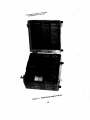
1·2. GENERAL. This manual contains information pertaining to the H337N Series Engine Test Set manufactured by Howell Instruments, lnc., Fort Worth, Texas. The Engine
Test Set (hereinafter referred to as the test set or the tester) is pictured in figure 1-1.
Tester parts are illustrated and identified in the Illustrated PartsBreakdown, Section VII.
1-3. PURPOSE. The purpose of this manual is to provide sufficient information for the
technician to understand, operate, calibrate, and maintain the tester.
1-4. SCOPE. In this manual are diagrams and the theory of operation of all tester circuitry, complete operation instructions sbowing cabling connections, a list of the caUbration equipment and procedures necessary to maintain the accuracy of the tester, and
troubleshooting and repair procedures.
1·5. ARRANGEMENT. This manual is arranged in the fOllowing sections:
Section
I
II
III
IV
V
VI
VII
VIII
Appendix A
Appendix B
Title
Introduction and General Information
Special Tools and Test Equipment
Preparation for Use and Shipment
Operation Instructions
Maintenance Instructions
Diagrams
Illustrated Parts Breakdown
Application Data
Descriptions of Integrated Circuits
Acceptance Test Procedure
1·6. ABBREVIATIONS AND SYMBOLS. Abbreviations and symbols used in this
manual are explained in the following list:
Abbreviation/Symbol
BIT
CAL.
CALIB.
CALIBA.
CJ
CK.
Meaning
built-in test
calibration
calibrated or calibration
calibrated
cold junction
check
1-1
Change 2
iHIS DOCUtJ\ENl' IS SUBJECiro iHE LEGEND
f\ESifl,IC'T\ONS ONiHE ,\iLl: PAGE
Figure 1-1. 1'\337'"series Engine Test set
THIS DOCUMENT IS SUBJECT TO THE LEGEND
RESTRICTIONS ON THE TITLE PAGE
1. Test aircraft temperature indicator.
2. Test resistance of aircraft temperature circuit.
3. Test insulation of aircraft temperature circuit.
4. Verify accuracy of aircraft rpm system.
5. Verify accuracy of aircraft temperature indicating system.
6. Monitor temperature during engine trimming.
7. Monitor rpm during engine trimming.
8. Monitor pressure during engine trimming.
9.
10.
11.
12.
Compute epr.
Measure engine torque.
Automatically correct temperature and rpm to standard day conditions.
Store and display or print up to 18 input data records (snapshots).
13. Store and display or print calibration and scaling data for up to 10 engine types.
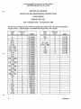
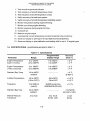
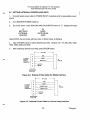
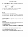
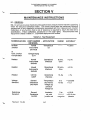
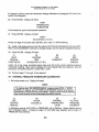
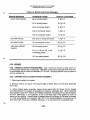
1-9. SPECIFICATIONS. Specifications are listed in table 1-1.
Table 1-1. Specifications
Parameter
Programmable
Display Range
Range
Accuracy
(Note 1)
Engine Temperature
(type K cr-al tic)
o to 1350°C
(0 to 2462°F)
o to 1350°C
Engine Temperature
(TF30 or-al curve)
o to
1360°C
(0 to 2480°F)
o to 1360°C
Standard Day Temp
-60 to 100°C
ambient
- -- - - - - - -
±4° C
@600°C
Ambient Temperature
-60 to 100°C
(-76 to 212° F)
-60 to100°C
-76 to 212°F
± 0.3° C
± 0.5° F
Frequency
10 to 30K Hz
(note 2)
30,000 counts max
(%RPM,RPM,PPH,HZ)
±O.1 %
Standard Day Freq
-60 to 100°C
ambient
Internal Pressure
Transducer
o to
2462°F
°
to 2480°F
- - -- - - - - - - -
o to 101.8
IN.HG. ASS
o to 5vdc
±2°C
± 4° F
±2°C
± 4° F
±0.2%RPM
@70HZ=100%
±0.25
IN.HG.
--.../
1-4
THIS DOCUMENT IS SUBJECT TO THE LEGEND
RESTRICTIONS ON THE TITLE PAGE
1-10. PHYSICAL DESCRIPTION. The tester is housed in a rugged, portable case. All
cable and hose connections, switches, controls, and displays are located on the deck.
The H337N Series part number assignment is as follows: H337N(
)tester includes
printer access without printer; H337NP-{
) tester includes printer.
1-6
THIS DOCUMENT ISSUBJECT TO THE LEGEND
RESTRICTIONS ON THETITLE PAGE
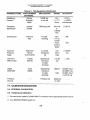
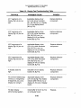
Table 2·1. Special Tools and Test Equipment List (Continued)
TOOL/EQUIPMENT
NOMENCLATURE
USE AND APPLICATION
General Resistance
DA763X
Resistance
decade
Cold junction cal;
insulation cal.
Electro Scientific
D862
Resistance
decade
TAM8 cal;
tc res cal.
Anadex
FS-600
Frequency
synthesizer
RPM accy chk.
Tektronix
432
Oscilloscope
Troubleshooting.
Wallace & Tiernan
61A-18-0100
Absolute
pressure gage
Int press xdcr cal.
Triplett
630-NS
Volt-ohmmilliammeter
Operational checkout.
Fluke
aaOOA
Digital
multimeter
Operational checkout.
-- - - -
Pressure source
Pressure cal.
2·2
THIS DOCUMENT IS SUBJECT TO THE LEGEND
RESTRICTIONS ON THE TITLE PAGE
SECTION III
PREPARATION FOR USE AND SHIPMENT
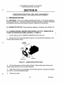
3-1. PREPARATION FOR USE.
3-2. UNPACKING. There are no special unpacking procedures. A list of items shipped is
included in Section VIII. The tester is ready for use after unpacking. Operation instructions
are contained in the instrument case lid as well as in Section IV of this manual.
3-3. ENGINE TEST SETUPS. Engine test setup diagrams, if included, are in Section VIII.
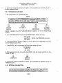
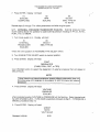
3-4. LOADING INTERNAL PRINTER PAPER (HOWELL PN C10717, MEMODYNE PN
PT-20B1) IN PRINTER MAP-20SBCL (FIGURE 4-11, SHEET 6).
1.
Loosen captive screws in PRINTER ACCESS door and lower door.
2. Depress both front panel slide latches (Figure 3-1) and pull printer mechanism out of
housing until mechanism stops.
THERMAL
PAPER ROLL.•~
;:r'
AXLESLOT
SLIDE LATCH
Figure 3-1. Loading Internal Printer Paper
3. Pull remaining paper out from under print head. Grasp empty paper roll and pull it
straight along axle slot and out of printer assembly.
4. Slide paper roll axle out of used paper roll and insert axle into new paper roll (Howell
pn C10717). DO NOT DISCARD AXLEl
5.
Raise load bracket.
3-1
Change 4
THIS DOCUMENT IS SUBJCT TO THE LEGEND
RESTRICTIONS ON THE TITLE PAGE
6. Slide axle (with new paper roll) into axle slot and seat the axle in bottom of slot. Be
sure paper is fed from rear and passes over paper roll. Paper should be cut straight for
easy insertion. Only outside paper surface is treated for printing.
7. Insert paper in slot formed by paper guide and print head until paper appears at front
. panel opening. Pull paper through front panel slot, close load bracket by pressing it
downwards, and check that when power is on, EOP LED turns off. If not, paper is not in
proper paper path. DTR light should be on when power is on.
8. Slide printer mechanism back into housing until both slide latches latch. Advance
paper by momentarily setting switch to FEED. Place switch in center position for normal
operation.
3-5. LOADING INTERNAL PRINTER PAPER (HOWELL PN C15055, MFE INSTRUMENT
CORP. PN PT21B1) IN PRINTER MAP-21CBC (FIGURE 4-11, SHEET 6).
1.
Loosen captive screws in PRINTER ACCESS door and lower door.
2. Rotate the paper advance knob (figure 4-11) downward to advance any remaining
paper out of the printer. Lift up on the head release lever to raise the print head from the
roller.
3. Lift up on both slide latches to release the slide assembly and pull the slide out of the
housing until it stops. Lift the spent paper roll and axle from the notches in the slide
assembly. Slide the axle out of the used paper roll. DO NOT DISCARD THE AXLE!
4. Break the seal on the new roll of paper. Tear off and discard the first layer of paper,
includinq the glue or tape seal. Tear or cut cleanly for easy paper insertion. Slide the axle
into the new paper roll and position the axle with the new roll above the notches in the slide
assembly. Be sure the paper is fed from the top of the roll; only the outside surface of the
paper is treated for printing.
5. Thread the paper into the paper slot and through the mechanism until it comes out the
slot of the front panel. The PAPER light on the front panel changes from on to flashing.
6. Push down on the paper roll to seat the axle firmly into the bottom of the notches.
Make sure the paper passes straight through the mechanism, then lower the head release
lever. The PAPER light should turn off.
7. Push the slide back into the housing until the latches engage. Press the front-panel
FEED button to check that the paper emerges smoothly from the mechanism. Press the
ON LINE button to resume operation.
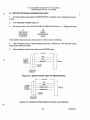
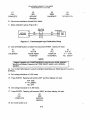
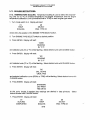
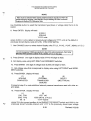
3-6. CABLE FOR OPTIONAL EXTERNAL PRINTER. If an external printer is to be used,
prepare the interface cable as shown in figure 3-2 or 3-3. The printer used with the tester
must be set to generate automatic Iinefeeds when sent carriage returns.
Change 4
3-2
THIS DOCUMENT IS SUBJECT TO THE LEGEND
RESTRICTIONS ON THE TITLE PAGE
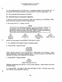
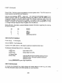
3-7. SETTING EXTERNAL PRINTER BAUD RATE.
1. Connect tester power cable to POWER INPUT receptacle and to appropriate power
source.
2.
Turn MASTER POWER switch on.
3.
Set mode switch under SCALING AND CALIBRATION door to 11. Display will read:
(2)
BAUD
RATE EQUAL
XXXX
(1)
SET BAUD
EXTERNAL
PRINTER
where XXXX, the previously set baud rate or default value, is flashing.
4.
Use CHANGE button to select desired baud rate. Choices are 110, 300, 600, 1200,
1800, 2000, 2400 and 3600.
5.
After selecting desired baud rate, press ENTER button.
1<
>1
GND
A
TOTESTER
EXTERNAL
PRINTER
CONNECTOR
25FT. MAX
READY
B
TO
PRINTER
C
F
EXTPTR
SENSE
G
MATES BENDIX
PT02A-12·8S
Figure 3-2. External Printer Cable for RS232 Interface
25 FT.MAX
TO TESTER
EXTERNAL
PRINTER
CONNECTOR
A
GND
B
READY
D
CURRENT LOOP +
TO
PRINTER
E
F
G
EXTPTR
SENSE
MATES BENDIX
PT02A·12·8S
Figure 3-3. External Printer Cable for Current Loop Interface
3-3
Change 4
THIS DOCUMENT IS SUBJCT TO THE LEGEND
RESTRICTIONS ON THE TITLE PAGE
NOTE
Current loop is driven by a 4.8 vdc source through a 56 ohm internal resistor.
Maximum allowable source current is 25 ma at high logic level. Maximum
available source current at low logic level is 0 ma (open collector).
3-8.
PREPARATION FOR SHIPMENT.
3-9. The tester should be surrounded with two inches of rubberized hog hair when it is
packed for shipment. Use the latest revision of specification MIL-P-116, method liB, and
JAN-P-100.
Change 4
3-4
THIS DOCUMENT IS SUBJECT TO THE LEGEND
RESTRICTIONS ON THE TITLE PAGE
SECTION III
PREPARATION FOR USE AND SHIPMENT
3-1. PREPARATION FOR USE.
3-2. UNPACKING. There are no special unpacking procedures. A list of items shipped is
included in Section VIII. The tester is ready for use after unpacking. Operation instructions
are contained in the instrument case lid as well as in Section IV of this manual.
3-3. ENGINE TEST SETUPS. Engine test setup diagrams, if included, are in Section VIII.
3-4. LOADING INTERNAL PRINTER PAPER (HOWELL PN C10717, MEMODYNE PN
PT-2081) IN PRINTER MAP-20SBCL (FIGURE 4-11, SHEET 6).
1.
Loosen captive screws in PRINTER ACCESS door and lower door.
2.
Depress both front panel slide latches (Figure 3-1) and pull printer mechanism out of
housing until mechanism stops.
THERMAL
PAPER ROLL.•~
;:r'
AXLESLOT
SLIDE LATCH
Figure 3-1. Loading Internal Printer Paper
3.
Pull remaining paper out from under print head. Grasp empty paper roll and pull it
straight along axle slot and out of printer assembly.
4.
Slide paper roll axle out of used paper roll and insert axle into new paper roll (Howell
pn C10717). DO NOT DISCARD AXLE!
5.
Raise load bracket.
3-1
Change 4
THIS DOCUMENT IS SUBJCT TO THE LEGEND
RESTRICTIONS ON THE TITLE PAGE
6. Slide axle (with new paper roll) into axle slot and seat the axle in bottom of slot. Be
sure paper is fed from rear and passes over paper roll. Paper should be cut straight for
easy insertion. Only outside paper surface is treated for printing.
7.
Insert paper in slot formed by paper guide and print head until paper appears at front
. panel opening. Pull paper through front panel slot, close load bracket by pressing it
downwards, and check that when power is on, EOP LED turns off. If not, paper is not in
proper paper path. DTR light should be on when power is on.
8. Slide printer mechanism back into housing until both slide latches latch. Advance
paper by momentarily setting switch to FEED. Place switch in center position for normal
operation.
3-5. LOADING INTERNAL PRINTER PAPER (HOWELL PN C15055, MFE INSTRUMENT
CORP. PN PT21B1) IN PRINTER MAP-21CBC (FIGURE 4-11, SHEET 6).
1.
Loosen captive screws in PRINTER ACCESS door and lower door.
2. Rotate the paper advance knob (figure 4-11) downward to advance any remaining
paper out of the printer. Lift up on the head release lever to raise the print head from the
roller.
3. Lift up on both slide latches to release the slide assembly and pull the slide out of the
housing until it stops. Lift the spent paper roll and axle from the notches in the slide
assembly. Slide the axle out of the used paper roll. DO NOT DISCARD THE AXLE!
4.
Break the seal on the new roll of paper. Tear off and discard the first layer of paper,
including the glue or tape seal. Tear or cut cleanly for easy paper insertion. Slide the axle
into the new paper roll and position the axle with the new roll above the notches in the slide
assembly. Be sure the paper is fed from the top of the roll; only the outside surface of the
paper is treated for printing.
5. Thread the paper into the paper slot and through the mechanism until it comes out the
slot of the front panel. The PAPER light on the front panel changes from on to flashing.
6.
Push down on the paper roll to seat the axle firmly into the bottom of the notches.
Make sure the paper passes straight through the mechanism, then lower the head release
lever. The PAPER light should turn off.
7. Push the slide back into the housing until the latches engage. Press the front-panel
FEED button to check that the paper emerges smoothly from the mechanism. Press the
ON LINE button to resume operation.
3-6. CABLE FOR OPTIONAL EXTERNAL PRINTER. If an external printer is to be used,
prepare the interface cable as shown in figure 3-2 or 3-3. The printer used with the tester
must be set to generate automatic linefeeds when sent carriage returns.
Change 4
3-2
THIS DOCUMENT IS SUBJECT TO THE LEGEND
RESTRICTIONS ON THE TITLE PAGE
3-7. SETTING EXTERNAL PRINTER BAUD RATE.
1. Connect tester power cable to POWER INPUT receptacle and to appropriate power
source.
2.
Turn MASTER POWER switch on.
3.
Set mode switch under SCALING AND CALIBRATION door to 11. Display will read:
(1)
SET BAUD
EXTERNAL
PRINTER
(2)
BAUD
RATE EQUAL
XXXX
where XXXX, the previously set baud rate or default value, is flashing.
4. Use CHANGE button to select desired baud rate. Choices are 110, 300, 600, 1200,
1800, 2000, 2400 and 3600.
5.
After selecting desired baud rate, press ENTER button.
1<
)1
GND
A
B
TOTESTER
EXTERNAL
PRINTER
CONNECTOR
25 FT.MAX
READY
RS232 DATA
C
F
TO
PRINTER
EXTPTR
SENSE
G
MATES BENDIX
PT02A-12·8S
Figure 3-2. External Printer Cable for RS232 Interface
25FT. MAX
TOTESTER
EXTERNAL
PRINTER
CONNECTOR
A
B
o
E
F
G
GND
READY
CURRENT LOOP +
TO
PRINTER
EXTPTR
SENSE
MATES BENDIX
PT02A-12-8S
Figure 3·3. External Printer Cable for Current Loop Interface
3-3
Change 4
THIS DOCUMENT IS SUBJCT TO THE LEGEND
RESTRICTIONS ON THE TITLE PAGE
NOTE
Current loop is driven by a 4.8 vdc source through a 56 ohm internal resistor.
Maximum allowable source current is 25 ma at high logic level. Maximum
available source current at low logic level is 0 ma (open collector).
3-8.
PREPARATION FOR SHIPMENT.
3-9. The tester should be surrounded with two inches of rubberized hog hair when it is
packed for shipment. Use the latest revision of specification MIL-P-116, method liB, and
JAN-P-100.
Change 4
3-4
THIS DOCUMENT IS SUBJECT TO THE LEGEND
RESTRICTIONS ON THE TITLE PAGE
SECTION IV
OPERATION INSTRUCTIONS
4-1. THEORY OF OPERATION.
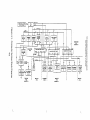
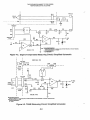
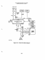
4-2. GENERAL. This section contains a brief discussion of the tester theory of operation as well as operation instructions. Included are a computer system block diagram,
simplified schematics of the signal measuring circuits, and a power flow block diagram.
Detailed descriptions of integrated circuits are included in Appendix A. Most circuitry is
located on four printed circuit boards, namely the computer board, 'the analog board,
the display board, and the power supply board.
4-3. COMPUTER SYSTEM. The tester is a combination digital voltmeter, millivolt
source, and constant current source which is microprocessor controlled. Tester functions are managed by the central processing unit (CPU, U6, figure 4-1) and the stored
program in the read-only memory (Ui ,U2). U6 is an 8-bit microprocessor which has the
capability of addressing 65K bytes of memory with its 16-bit address lines. The 8-bit
data bus is bi-directional as well as three-state. A 5:,MHz clock osoillator provides the
necessary timing. This clock is divided by 2 by CPU U6 and is further divided by
counter/port/ram U11 to provide the built-in-test (BIT) frequencies for the frequency
measuring circuits.
4-4. Switches. in the deck switch matrix (figure 4-1) and jumper plug Pi 04 determine
which subroutines are run by the microprocessor. When P104 is removed, the tester
goes into the internal calibration routine. The matrix switch having the highest priority
for determining microprocessor action is the mode switch (figure 4-11, index 22) under
the SCALING AND CALIBRATION access door. Switches with lesser priority in the
order most-to-Ieast are the FUNCTION SELECT switch and the TEMP SELECT switch.
4-5. Three counter/port/ram's (U1i-U13) on the computer board (figure 4-1) provide
the. input-output (I/O) interface needed to read switch positions, to accumulate data
from analog-to-digital and synchro converters, and to output data to printers. These circuits also contain timers which provide the frequency measurement capability. Each circuit contains 128 bytes of ram, two 16-bit programmable binary down-counters, and 19
programmable I/O bits arranged as three separate ports (port A - 8 bits, port B - 8 bits,
and port C - 3 bits). Each bit is individually definable as an input or output. Port bits can
be set or cleared individually and can be written or read in bytes. Following is a list of
the circuits with their functions.
COUNTER/PORT/RAM
FUNCTIONS;
U11 - portA
(1PA bits)
Obtain data from ADC U 17 and synchro converter
U16, when used.
U11 - port B
(1PB bits)
Control ADC and synchro converter functions. Sense
tester switch closures.
4-1
I
!!
co
c.UtZ.:'''N
~ .....
CLOCK OSCILLATOR
VI,RI7, CIS, elG
I 10/M
CPU
u6
•
c
~
...
I
3
-
"C
C
(l)
OCTAL
BUFFER
UIO
I
I\)
en
3
l:D
0'
0
;II;
c
OJ
co
~
OJ
3
COMPUTER
PCB
I
I
UI~
'<
(l)
• .:ttl a,.rt
16-LINE
DECODER
(f)
al-
't
zl,
J
~
0'-01
IIIEMORY
UI,U2
UT
r
I
5E61<£"T
CO"TIIO~
•
'1
~
DRIVER
TRANSlSTORS
I"-SEGMENT
DISPLAYS
01-11'6
11-114
~
l
DISPLAY
PCB.
BHi:Glin-J
I
I
I
I
I
E
ua
,jn
aJ
.. t
•
8
IV
B
un
ll'O,""
~ORT 8
P'OfIT c.
CE
COLINTERf PORT fR.... 2
"'OftT.
CONT"OL
I
I
I z
.[, 8 If
I
I
I
"DC
UI7
I
TRIIIIMER
DECK SW
MATRIX
PCB
I
I
I
I
I
I
ANALOG
I
_(UIIT
1I'0000Te
u'2
---,
c
t
~
't II
ANALOe:
SWITCHES
UrU6
6
FREDUENCY
I.OGIC
U3, UI4
I
DECK
I
I
I
I
IL.. _ _ _ _ ...JI
I
TRIMMER
I
WO
-iC
~s::
Om
BHZ6:l1~·1
1
CE
Ul3
POAT I
:::!z
I
O-i
JOfll
COUNTERJPORTJRAM 3
,o,n A
mO
PCB
I
zwen
O~
lI'MT C
I--.,--t------,.--I
•
I
I 1
!
I
I
r-1
I
I
I
3
I
lOIN
:DO
COMPUTER
a
I
CE
"-r--I---y--'-
Z[,
Ci5
'Of'
BIT
FRED
B
-i
I
CHIP !HA!lLE
GATtMG
US
e:OI1NTtR J PORT J RAM I
I
I
•
OCTAl
DECODER
I
~ '~d
1-----OU' BuS
L-_-
DISPLAY
DRIVERS
UI-UI4
~
RAND;)..
ACCESS
MEMORY
U!I
PROGRAM
ADDRESS
LATCH
- -- -- ~.r-- i
~
~
~
1
~
•
r
a
(l)
o0
ADO"US 8uS
DATAl
AbOrt!!, au!
-I
I
-\
FUNCTION
SELECT SW
51
I
I
I
I
3PC"
~
INTERNAL.
PRINTER
EXTERNAL.
PRINTER
I
I
I
I
I
JUIIPER
PLUG
PIO'\
of.
ANALOG
ANALOG
PCB
PCB
BHZ56J7-1
ZlJl
-i'-
:em
mO
-i
:::!-i
-i0
hi-i
"U I
):om
(j)r
mm
G)
m
Z
o
THIS DOCUMENTIS SUBJECTTO THE LEGEND
RESTRICTIONS ON THE TITLE PAGE
COUNTER/PORT/RAM
FUNCTIONS
U11 - port C
(1 PC bits)
Sense tester switch closures.
U12 - port A
(2PA bits)
Multiplex inputs to amplifier U9. Select appropriate
amplifier U9 offset circuit. Multiplex signals in ADC
U17. Switch constant current source on and off when
making resistance measurements.
U12 - port 8
(2PB bits)
Select appropriate amplifier U7 offset circuit for frequency measurements. Drive frequency timing logic.
U12 - port C
(2PC bits)
Multiplex frequency signals to frequency amplifier U7.
U13 - port A
(3PA bits)
Decode FUNCTION SELECT switch position. Control
internal and external printer.
U13 - port B
(3PB bits)
Sense tester switch positions.
U13 - port C
(3PC bits)
Sense presence of jumper. plug P104 for internal
calibration mode.
...
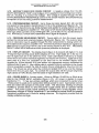
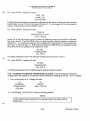
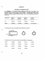
4-6. ENGINE TEMPERATURE MEASURING CIRCUIT. The engine temperature sig-
nal from the engine thermocouples follows the path shown in figure 4-2. Switch positions required when. measuring engine temperature are listed in the figure. The signal is
amplified by U9 and offset by U2 on the analog board before being applied to adc converter U17. An input of 5 vdc will cause U17 to have a full-range (binary 4095) output.
Analog switch U3, driven by port A bit 5 from counter/port/ram U11 on the computer
board, controls the amount of offset voltage applied to U9 from U2. Port A bits 2 and 3
address one-of-four decoder U8 which drives analog switch U5 to route the thermocouple signal to U9.
4·7. To cancel any. effect on the readings as a result of temperature variations in the
junction between the tester's copper wiring and the thermocouple wires, a compensating junction (COMP· JCT) is used in the negative lead of the input circuit. In close
proximity to this junction is a thermistor (RT1) for junction temperature measurement.
. The microprocessor reads the thermistor signal and automatically references the thermocouple readings to DoC.
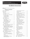
4·8. AMBIENT TEMPERATURE MEASURING CIRCUIT. Agure 4-3 shows the circuit
used to measure ambient temperature. An RTD probe, which has a resistance of approximately 108 ohms at 70°F, is connected to connector TAMB. U9 amplifies the signal
before it is applied to ADC U17. Should the probe open, 5 vdc will charge filter
capacitor C4 through resistors R43, Ri9, and R20, causing an upscale drift in the ambient temperature display.
THIS DOCUMENT IS SUBJECT TO THE LEGEND
RESTRICTIONS ON THE TITLE PAGE
,
:
I
SWI4
14
E.~GI~E
~
TIC'S
PIOI/SIOI
I
.
E;T ..I
"'TCR--i~ 51" Il,
..
LI
____ ,
DECK
S102!P202
2PA2
2PAl
I
t-_L1---------1
4-
.J
COMP
J CT
H A
~
--,I::;J B
U8
RI1
21-,-,10,--_~--.
RIJ
2PAS
COMPUlER I
_P.E~_...J
R40
R~I
sv
ell12
Rsa
REF
RJ9
R~g
ANALOG PCB
ReQ! Jlred SWitch Positions·
FUNCTION SRECT (SI on analog pcb) to NORM. READING or STD DAY READING.
TEMP SELECT (SWI4) to NORMAL
ConnectQr JdenllffcBlloo-
J4 - TEMP/RPM
Figure 4·2. Engine Temperature Measuring Circuit, Simplified Schematic
I
•
I
:
0;0201
I
I
I
I
I
I
COMPUTER PCB
P201
TO PORTS
3
TEMP
SElECT
SWl4
:
I PB, 3 PH
1--- ------ - - - -
I
I
I;=:====~.J
SV
REf
I
I
I
JS
PIOI/SIOI
~EXC
+51G
TAMB
PROBE
~.J\J'V'~ __- _ - . TO AOe
UII
to
-S16
CR12
5V REF
-EXC
EXT
TESTER
R21
DECK
R40
R39
RH
SV 4-.I\II,/\,.---'''''I\r-J\JVv-....
RSO
REf
-15V
R49
ANALOG PCB
BeQII!red Swltch positions·
FUNCTION SELECT (SI on analog pcb) to NORM. READING, STD DAY READING, 0' AIRCRAFT INDICATOR ON.
TEMP SELECT (SWt4) to TAMB.
Connector IdentificAtion'
J5-TAMB.
Figure 4-3. TAMS Measuring Circuit, Simplified Schematic
4·4
THIS DOCUMENT IS SUBJECT TO THE LEGEND
RESTRICTIONS ON THETITLEPAGE
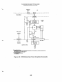
4-9. INSULATION RESISTANCE MEASURING CIRCUIT. A constant current, generated by the 5 vdc supply and the circuitry of U1 and Q1 (figure 4-4) flows through the
unknown insulation resistance, Rx , of the aircraft engine temperature circuit. This current generates a voltage at the + input of buffer amplifier U2 on the analog board. The
voltage is divided by resistors R14 and R15 before being applied to amplifier U9. The
tester ZERO control adjusts the display to zero by adJusting·the offset of U9 when Rx is
jumpered. Thermocouple effects are canceled by measuring the circuit output with the
current source turned off and subtracting this value from the output with the current
source turned on. Switch 01 turns the current source on and off.
IV REf
AKAlOG PCI
RU
~=r~-L
,
~
I
__________ - - _l
<-r----.--'-,
I
Ell
BeQ'''rod SWItch PnsUlon'FUNCTION SELECT (SI on analog pcb) 10 INSULATION
TEMP SELECT (SW14) 10TAMB or NORMAL
Connector Ideollflcallpoo
J4 - TEMP/RPM
'----
EHCIKE
Aen
HARKUS
~NO
I
I
IL
TUTER
D[C~
- - -- --~
.. 'IV
RI
-IIV
ZERO
_
Figure 4-4. Insulation Resistance Measuring Circuit, Simplified Schematic
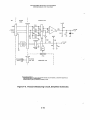
4-10. ENGINE TC RESISTANCE MEASURING CIRCUIT. A constant current, generated by the 5 vdc supply and the circuitry of U1and 01 (figure 4-5) flows through the
resistance spool and thermocouple wiring of the aircraft thermocouple circuit. The voltage thus generated is amplified by amplifier U9 on the analog board and applied to ADC
U17. As in the insulation resistance measuring circuit, the tester ZERO control adjusts
the offset of U9. This is done while jumpering the signal input pins at the aircraft to subtract the tester and test cable resistance from the tester readings. Thermocouple effects
'.
are canceled as explained in paragraph 4-9.
4·11. AIRCRAFT INSTRUMENT RESISTANCE SET CIRCUIT. When the aircraft instrument resistance is set prior to making the D'Arsonval temperature indicator test, the
test cable leads are jumpered at the indicator (figure 4-6). The constant current generated by the 5 vdc supply and the circuitry of U1 and 01 in the analog board flows
through the AIRCRAFT INSTRUMENT RESISTANCE control (R3) and the wiring of the
. tester and test cable to ground. The generated voltage is amplified by U9 and applied
to ADC U17. R3 is adjusted until the tester displays the resistance value specified on
. the aircraft indicator. Thermocouple effects are canceled as explained in paragraph 4-9.
4·5
THIS DOCUMENTIS SUBJECTTO THE LEGEND
RESTRICTIONS ON THE TITLE PAGE
4·12. AIRCRAFT INDICATOR CHECK CIRCUIT. A negative voltage from the AIRCRAFT INSTRUMENT TEMP control (figure 4-7) is applied to the inverting input of amplifier U1, resulting in a positive test voltage. This voltage is applied through the AIRCRAFT INSTRUMENT RESISTANCE control to the aircraft indicator and simultaneously
to amplifier U9 on the analog board for measurement.
4·13. RPM MEASURING CIRCUIT. Up to three rpm input signals (N1, N2, and N3)
are applied to three.isolation transformers (f1-T3) on the analog board (figure 4-8). The
outputs of the transformers are diode-clamped and applied 10 analog switch U4 which
multiplexes the signals to amplifier U7. The output of U7 clocks dual-D flip-flop U3 in the
timer logic which consists of U3, NAND gate U14, port B bits of U12, and the timers in
U12. RPM SELECT switch SW13 determines which signal is displayed.
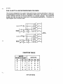
4·14. PRESSURE MEASURING CIRCUIT. Twenty-eight vdc from the power supply
excites the internal and external pressure transducers (figure 4-9). The external pressure or ratiometric input is applied through RC filter components to analog switch U6.
U6 multiplexes the signal to amplifier U10. The internal pressure transducer signal is applied through jumper plug P104 to one of the analog inputs of ADC U17. PRESSURE
SELECT switch SW10 determines which pressure parameter is displayed.
4·15. DISPLAY CIRCUIT. The display board (figure 4-1) presents 28 digits in 14 dual
14-segment light emitting diode (LED) displays (11-114). Eight diqits are in the top row
and 10 digits each are in the other two rows. Each dual display is' driven by a display
driver which can control individual segments and has its own memory. Eight bits of segment data at a time are presented on the data bus to the enabled display driver
(enabled by 16-line decoder U15) and written into appropriate memory addressed by
address lines AD and At. After display data is updated, internal oscillators in the display
drivers sequentially present the data to output drivers whicb.....dlrectly. drive the LED displays. The drivers are active when the control pin labeled SOE is low, and the displays
blank when this pin goes high. To correlate the output data with the proper segments,
digit outputs (D1-D4) directly drive the bases of digit transistors 01-056.
4-16. POWER SUPPLY. Primary power, 115vac or 230vac, 50-400 Hz; or 28vdc is applied to the POWER INPUT connector (figure 4-10). AC power is applied to power
transformer T1. T1 has two primary windings which are connected in parallel when
115vac power is used and in series when 23Dvac power is used. Appropriate connections are made with jumpers in the power cable. The secondary winding is full-wave
rectified to provide 28vdc to drive the power supply board and an optional internal
printer. The power supply board contains an inverter and a 5-volt regulator circuit.
Secondary voltages of inverter transformer T1 are rectified to provide 28vdc for pressure
transducer excitation and e lSvdc for analog reference. The regulator provides 5vdc for
display excitation and loqic.
4·6
THIS DOCUMENTIS SUBJECTTO THE LEGEND
RESTRICTIONS ON THE TITLE PAGE
COMPUTER PCB
5VREF
lPAl
R51
TO lOC
> ...."V\I\r-~-UIl
CI9
5V
141
J
RSD
REf
RJI
CRf2
1149
--- --- -- - - - __.r- -t,---:''':'''''',-J--l
EXT
RES
SPOOL
BCQulntd Switch PosUIQos'
FUNCTION SELECT (51 on analog pcb) to TC RESISTANCE
TEMP SELECT (SWI4) \0 TAMB or NORMAL
I
TESTER
DECK
+15Y
1..._-
-15V
_
Concedor IdenllficRtloo·
J4 • TEMP/RPM
Figure 4-5. Thermocouple Resistance Measuring Circuit, Simplified Schematic
COMPUTER PCB
5V REF
2PAl
2PA2 2PAJ
2PA5
SIOllP202
TO AOC
> ......-vvv-..-...-- 1111
CRI2
SV
R4'
REF
ft4t
TESTER OECK
EXT
BcqtJlred Switch paslUgos·
FUNCTION SelECT (Sl on analog pcb) to I SET
TEMP SELECT (SWI4) \0 TAMB or NORMAL
Conneclor Identification:
J4 • TEMP/RPM
Figure 4-6. Aircraft Instrument Resistance Set Circuit, Simplified Schematic
4-7
THIS DOCUMENT IS SUBJECT TO THE LEGEND
RESTRICTIONS ON THE TITLE PAGE
TESTER
DECK
I
I
ANALOG PCB
I
I
I
I
-ISV
I
R&
TESTER
I
DECK
I
I
PIOl{SIOI
EXT
I
I
I
Pl01/S101
H
ACfT
R3
III STR
lEMP
ACFT
IHSTR
___ -J
RES
of.
ACFT
IND
I
I
---,
COMPUTER I
PCB
I
SI02/P202
2PA2
14
I
I
I
R44
I
A
11 8
2PA3
I
-----~SlF
I
IL
UB
IL
_
~C5
2PAS
I
L------------l
----'
US ~-----"-I
R51
R48
5V·_ _-"\/'u..... _>__-4
C19
REF
R50
5V·_'V\Ar...-----"urv\,_-I-----,
REf
J
R39
RU
ReQuired Switch PQsJUoos·
.
FUNCTION SELECT (SI on analog pcb) to INDICATOR CHK
TEMP SELECT (SW14) 10 TAMB 0, NORMAL
CllonedQrJdllOlllli:~
J4 - TEMP/RPM
Figure 4-7. Aircraft Indicator Check Circuit, Simplified Schematic
4-8
THIS DOCUMENT IS SUBJECT TO THE LEGEND
RESTRICTIONS ON THE TITLE PAGE
FREQUENCY
INPUTS
EXT
TESTER DECK
r - - - - - - ' - - - T -.... ,
+ 5V
-- -
--------
I
I
R35
I
I
,
I
I
COM
ISOLATION
tRANSfORMERS
TH3
I
PCB
.
'(
5 -
I
U4
I
I
I
I
RPM SElECT
ANALOG
, I
1
f UI
J
A
2
3
•
I
I
I
R32
L..-._-..-'V\.f\r"...... + 5V
I
__ 1.._
2PCO 2Ptl
BIT
FREa
TO PORn
lpe,3P8
TIMER lOGIC
U3. U12. UI4
COMPUTER PCB
DATA
BUS
BoQlaJrcd SwItch PQSltlODS·
FUNCTION SELECT (Sl on analogpcbllo NORM.READING, STDDAYREADING, or AIRCRAFT INPICATORON.
TEMPSELECT (SW14) to TAMB or NORMAL
RPMSELECT (SWt3) 10N1. N2, or N3.
Connector
I~~
J3-RPMINPUTINSTRCAB~
J4 • TEMPIRPM.
Figure 4-8. RPM Measuring Circuit, Simplified Schematic
4-9
THIS DOCUMENT IS SUBJECT TO THE LEGEND
RESTRICTIONS ON THE TITLE PAGE
.
I
I
TESTER
EXT
ANALOG PCB
I
DECK
sv REF
Pl01(SlO1
R53
+SIG
R61
ro AOC
;r-.rvvv-+-----.--<t--.. U11
- SIG/REF
+ REF
R63
n
I
5V REF
56
I
I
R66
I
I
INT
XOCR
XDI
I
-1--.. .
+
-
I
Ill1
28V
r - - - -- -
I
I
S101!P101
:PRESSURE~TO PORTS
I
TO AUC
IC20
I
I
I
CRt)
SElECT ~
I
-U
I
I
I
I
IPB. 3PB
S101/Pl01
----l
lPM
COMPUTER PCB
I
I
I
I
1
BClluhcdJlwllclLl?D:I1UDD~
FUNCTION SEl.ECT (SI on I1nl1109 pcb) to NORM. READING, STD DAY READING, 0, AIRCRAFT INDICATOR ON.
TEMP SELECT (SW14) to TAMB or NORMAl.
PRESSURE SELECT (SW10) to INTERNAL, EXTERNAL, or EPR
Figure 4-9. Pressure Measuring Circuit, Simplified Schematic
4-10
THIS DOCUMENT IS SUBJECT TO THE LEGEND
RESTRICTIONS ON THE TITLEPAGE
POWER INPUT
115/230
28
VAC OR VDe
S
l
------
MASTER
X I
CB 2 (
~OWER
PI21
Sl2
SWI
CB I (
CA5
28V
53011 . --.
P3QI
DISPLAY
80ARD
t
===:=;:=:;:=:;:)
15
V
BH26~73-1
SP402
402/
S203/P203
,......_""""-L...----,
6
-15
V
,
eRa
S303/P303
V
COMPUTER
BOARD
ACFT
INSTR
ZERO
8H26575-1
·'S202/P2021------1
RI
-
ANALOG
BOARD
BH26637-1
TO TEMP
SELECT
SIOI/ ' - - - - - - '
PIOI
SW
* OPTION
Figure 4-10. Power Flow Block Diagram
4-11
THIS DOCUMENT IS SUBJECT TO THE LEGEND
RESTRICTIONS ON THE TITLE PAGE
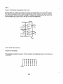
4-17. OPERATION INSTRUCTIONS.
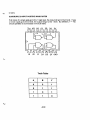
4.18. INDICATORS AND CONTROLS. Tester indicators and controls are illustrated and
listed with their functions in Figure 4-11. Test setups used with specific aircraft and engines
are illustratedin Section VIII.
°
3
2
1
...
_
4 5
6
7
8
9
10
11
...-..-
on
f"R tITOl
27
§
0/
PRIm:
Ie' 3Y
26
13
0>
~
D[
25
---------0'1
I
i
OJ
24
123YS R.P.M.
I
23
~---~
g
il
04.
3"
22
2"
17
123YS F T.lll.
I-
0
.'1
"8
"9
1• Jill
nlE: T1'P£
E I E T'l'PE
1
2
:3
4
:5
6
7
9
9
EXIERtW.
~l
1"M:ssl.M:
SOLCT
SELECT
21
20
19
Figure 4-11. Tester Indicators and Controls. (Sheet 1 of 7)
Change 2
4-12
18
THIS DOCUMENTIS SUBJECTTO THE LEGEND
RESTRICTIONS ON THE TITLE PAGE
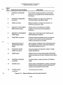
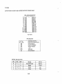
INDEX
NO.
INDICATOR OR CONTROL
FUNCTION
1
INTERNAL PRESSUR.E
port
Allows either ambient pressure or some other
pressure to be applied to the internal pressure
transducer.
2
EXTERNAL PRESSURE
connector
Makes excitation and signal connections to
external pressure transducer cable.
3
TAMB connector
Makes excitation and signal connections to
ambient temperature cable.
4
AIRCRAFf INSTRUMENT
RESISTANCE adjust
Adjusts test circuit resistance to values
required to test 0'Arsonval temperature
indicators.
5
AIRCRAFf INSTRUMENT
TEMP adjust
Adjusts level of test signal when testing an aircraft temperature indicator.
6
TEMP/RPM connector
Connects engine temperature and rpm signals
to tester and connects aircraft temperature
indicator test signal to test cable.
7
INSULATION and TC
RESISTANCE ZERO
adjust
Zeros resistance display when measuring insulation resistance and when measuring resistance
of aircraft temperature circuit.
8
RPM INPUT INSTR
CABLE connector
Connects engine rpm signals to tester in single
engine applications.
9
PRINT button
Initiates printout of input data stored with STORE
button and printout of tester calibration and scaling
data.
10
EXTERNAL PRINTER
connector
Connects tester to external printer I/O interface
cable.
11
STORE button
Stores date and identification number, trim target,
ambient pressure setting, ambient temperature
setting, and snapshots of input data.
12
POWER INPUT
connector
Connects power to tester.
'-"
Figure 4-11. Tester Indicators and Controls (Sheet 2)
4-13
THIS DOCUMENT IS SUBJECT TO THE LEGEND
RESTRICTIONS ON THE TITLE PAGE
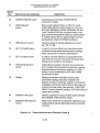
INDEX
NO.
INDICATOR OR CONTROL
FUNCTION
13
MASTER POWER switch
Applies input power from POWER INPUT
connector to tester.
14
TEMP SELECT
switch
When mode switch (index no. 22) is to 0 and
FUNCTION SELECT switch (index no. 27) is to
STD DAY REApING, NORM. READING, OR AIRCRAFT INDICATOR ON, programs tester to display ambient temperature reading or setting when
in TAMS position and to display engine harness
temperatures when in NORMAL positions.
15
RPM SELECT switch
Programs tester to display selected rpm input
(N1, N2, or N3).
16
SET TO PAMB button
Is used to remove offset from internal and external absolute-type pressure transducer readings
when transducer is vented to atmosphere.
17
SET TO ZERO button
Is used to remove offset from gauge/differential
type external pressure transducer readings when
transducer is vented to atmosphere.
18
PRESSURE SELECT
switch
Depending on position of switch, it programs tester to display internal pressure transducer reading,
external pressure transducer reading or PAMS
setting, or epr if parameters (PINT and PAMS)
are properly scaled.
19
Display
Displays parameter calibration/scaling data,
parameter readings and data, indicator test
signals, resistance readings, operator commands!
messages, and built-in-test functions depending on
position of mode switch (first priority), FUNCTION
SELECT switch (second priority), and TEMP SELECT
switch (third priority).
20
ENGINE TYPE card
Used by operator to record engine types selected
with ENGINE TYPE SELECT switch.
21
ENGINE TYPE SELECT
switch
Determines which set of parameter calibration and
scaling data is used to generate engine parameter
readings.
Figure 4-11. Tester Indicators and Controls (Sheet 3)
4-14
.:»
THISDOCUMENT IS SUBJECT TO THE LEGEND
RESTRICTIONS ON THETITLEPAGE
INDEX
NO.
22
INDICATOR OR CONTROL
Mode switch
FUNCTION
Switch with highest priority in determining tester
functions. Switch positions and functions follow.
o- normal.
Tester functions are determined by
FUNCTION SELECT switch (second priority)
and TEMP SELECT switch (third priority).
1 - read and print stored calibration and scaling
data.
2 - engine temperature scaling.
3 - rpm scaling.
4 - external pressure transducer scaling.
5 - internal pressure.transducer scaling.
6 - temperature calibration of engine temperature
and TAMS probe.
7 - external pressure transducer calibration.
8 - internal pressure transducer calibration.
9 - insulation resistance calibration.
10 - thermocouple resistance calibration.
11 - set external printer-baud rate.
23
24
CHANGE button
May be used to step through tester internal
calibration displays. Is used to step through
calibration and scaling data in mode 1. In calibration and scaling modes, is used to select
temperature parameters, temperature calibration
curves, engineering units, calibration input types,
pressure types, scaling types, and to answer
yes/no questions.
ENTER button
Causes the storing of selections made with
the CHANGE button and of settings made with
LEFT-RIGHT and INCREMENT switches.
Figure 4-11. Tester Indicators and Controls (Sheet 4)
4-15
THIS DOCUMENT IS SUBJECT TO THE LEGEND
RESTRICTIONS ON THE TITLE PAGE
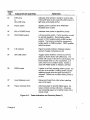
INDEX
NO.
FUNCTION
INDICATOR OR CONTROL
25
LEFT-RIGHT switch
Selects digit/character to be incremented with
INCREMENT switch. Steps display through
stored data.
26
INCREMENT switch
Adjusts calibration and scaling values when in
calibration and scaling modes. Adjusts identification number setting, trim target setting, PAMS
setting, and TAMS setting when in normal mode.
27
FUNCTION SELECT
switch
When tester is in normal mode (mode 0), switch
has absolute control of tester function in the following positions.
INSULATION - tester displays aircraft thermocouple
harness insulation resistance.
TIC RESISTANCE - tester displays aircraft thermocouple circuit resistance.
INDICATOR CHK - tester displays setting of
AIRCRAFT INSTRUMENT TEMP adjust.
SET - tester displays setting of AIRCRAFT INSTRUMENT RESISTANCE adjust,
BUILT IN TEST - one position tests display and CPU
hardware (includes RAM, rpm circuit, and AID
converter). Other position tests printer.
IDENT NO. SET - tester displays current identification
number setting and allows operator to change setting.
Then it displays current trim target setting and allows
operator to change setting.
PAMB SET - tester displays current PAMS setting and
allows operator to change setting.
TAMB SET OR PROBE - tester displays current TAMS
reading if probe is connected or allows operator to set
TAMS value if probe is not connected.
Figure 4-11. Tester Indicators and Controls (Sheet 5)
4-16
THIS DOCUMENT IS SUBJECT TO THE LEGEND
RESTRICTIONS ON THE TITLE PAGE
INDEX
NO.
INDICATOR OR CONTROL
FUNCTION
When TEMP SELECT switch is to NORMAL,
tester functions corresponding to other
FUNCTION SELECT positions are as follows:
STD DAY READING - tester displays selected
pressure and standard day corrected values of
engine temperature and selected rpm.
NORM. READING - Tester displays selected
pressure and uncorrected values of engine
temperature and selected rpm.
AIRCRAFT INDICATOR ON - Engine temperature harness signal is applied to aircraft indicator. Tester displays selected pressure and
uncorrected value of selected rpm. Temperature display reads Ale IND.
28
29
30
32
28
\. I
.---§~
--;
:)
~
-
V
/~
~
-
-
~
a<
U
POWER
ONLINE
00E""---Ht-- 30
PAPER
31
29
31
32
1£Sf
E
34
o
33
FEED
FEED'+itj-
PRINTER MAP-21 CBC
PRINTER MAP-20SBCL
28
Printer slide latch
Holds printer assembly in case.
29
EOP lamp
or
PAPER lamp
When lit, indicates printer is out-of-paper or
paper is not in proper path. Printer is disabled
when lamp is lit. PAPER lamp flashes when
printer has paper but head release lever is in
released position.
Figure 4-11. Tester Indicators and Controls (Sheet 6)
4-17
Change 4
INDEX
NO.
FUNCTION
INDICATOR OR CONTROL
30
DTR lamp
or
ON LINE lamp
Indicates when printer is ready to receive data.
If ON LINE lamp is off, press ON LINE switch to
light lamp and enable printer.
31
Power switch
Applies power to printer when PRINTER
ACCESS door is open.
32
ON or POWER lamp
Indicates when power is applied to printer.
33
TEST-FEED switch
A three-position switch. Center position is used
for normal operation. Momentarily putting
switch in TEST position starts a 385-line test
printout. Test may be ended by momentarily
putting switch in FEED position. FEED position
advances paper.
34
F-E indicator
Paper full-empty indicator indicates relative
amount of paper remaining on roll.
35
ON LINE switch
Toggles printer between on-line and off-line
status as shown by the ON LINE lamp. The
printer will not go on-line if it is out-of-paper, the
head release lever is in the up position, or if
some other error condition exists. Switch is
used with FEED switch to initiate a self-test.
36
FEED switch
If printer is off-line, pressing switch causes current line to be printed. Holding switch causes
additional paper to be fed until the switch is
released. Switch has no effect when printer Is
on-line.
37
Head Release Lever
Raises print head from roller when installing
new roll of paper.
38
Paper Advance Knob
Advances paper to provide blank space between printout and tear-off point. Advances
any remaining paper out of printer when roll is
nearly empty.
Figure 4-11. Tester Indicators and Controls (Sheet 7)
Change 4
4-18
THIS DOCUMENT IS SUBJECT TO THE LEGEND
RESTRICTIONS ON THE TITLE PAGE
CAUTION
When not calibrating the tester, do not press ENTER button when one of the
calibration modes (modes 6-11) is selected. Doing this will alter the calibration
of the selected parameter.
It is recommended that a printout of calibration and scaling data be obtained
prior to each use of the tester per instructions in paragraph 5-22.
NOTE
Calibration and scaling procedures of Section V shall have been accomplished prior
to using the tester. Calibration and scaling values applicable to particular engines
are included in Section VIII.
During normal operation, mode switch under SCALING AND CALIBRATION access
door must be set to 00. Printer TEST-FEED switch must be set to center position.
With an open input condition, NORMAL TEMP SELECT display drifts downscale to
approximately 60°C (140°F) and TAMS TEMP SELECT display indicates TAMS set
value.
Assure that date/engine identification numbers are entered before starting engine.
4-18A/(4-18B blank)
Change 4
THIS DOCUMENTIS SUBJECT TO THE LEGEND
RESTRICTIONS ON THE TITLEPAGE
'-"
4·19. POWER UP PROCEDURE.
1. Position MASTER POWER switch to OFF.
WARNING
To prevent electrical shock to personnel and possible damage to tester, always
use a three-wire grounded power cable when powering the tester with ae powerl
2. Connect power cable to POWER INPUT receptacle and to power source.
3. Turn MASTER POWER switch on and allow a 15 minute warmup.
4. Turn FUNCTION SELECT switch clockwise to first BUILT IN TEST position. As tester
performs built-in tests, display sequence will' be as follows:
(1)
DISPLAY
TEST
(3)
(5)
(6)
(7)
CPU
HARDWARE
TEST
CPU
HARDWARE
TEST
BUILT IN
TEST
COMPLETE
(4)
Display sequence repeats if FUNCTION SELECT switch is left in BUILT IN TEST position. Note that displays 2 through 4 test all segments of the display. If tester fails this
test, refer to Section V.
NOTE
If a printer Is not used, Is disconnected, is not turned on, or is out-of-paper, then
display will read as follows In the next step:
(1)
PRINTER
TEST
(2)
NO
PRINTER
READY
5. Open PRINTER ACCESS door and turn FUNCTION SELECT switch to next BUILT IN
TEST position. Display will continue to cycle through the following sequence as long as
the switch is left in this position:
(1)
PRINTER
TEST
(2)
(3)
(4)
FT. WORTH·
H337N
HOWELL
INSTR.INC.
3479 WEST
VICKERY
4·19
TEXAS
76107
THIS DOCUMENT is SUBJECT TO THE LEGEND
RESTRICTIONS ON THE TiTLE PAGE
(5)
(817)
336-7411
(6)
PRINTER
TEST
COMPLETE
While display goes through the above sequence, printer prints the following:
ABCDEFGHIJKLMNOPQRST
UVWXYZabcdefghijklmn
opqrstuvwxyz12345678
90/<>%
HOWELL INSTRUMENTS
3479 WEST VICKERY
FORT WORTH TEXAS
76107
(817) 336-7411
PRINT TEST COMPLETE
4·20. SETTING IDENTIFICATION AND TRIM TARGET NUMBERS. Ten characters
common to all positions of the ENGINE TYPE SELECT switch may be used to set the
date and/or an identification number and an additional ten characters may be used to
set a trim target. Once set, numbers appear in all subsequent engine data printouts
until changed.
NOTE
Changing identification number causes subsequent snapshot (recording)
numbers to start over with #001. Refer to paragraph 4-29 through 4-31.
1. Turn FUNCTION SELECT switch to IDENT NO. SET. Display will read as follows:
SET DATE
AND 1.0.
(10 characters)
Set date and/or identification number using the 10 characters in the bottom row. First
four left-hand characters may be set to 0-9 and remaining characters may be alphabeticalor numerical. Press up on the INCREMENT switch to change value of flashing
character. Hold INCREMENT switch in up position for continuous changes. Use LEFTRIGHT switch to select other character positions.
2. After making setting, press STORE button. Display will read:
4-20
THIS DOCUMENTIS SUBJECT TO THE LEGEND
RESTRICTIONS ON THE TITLE PAGE
SET TRIM
TARGET
(10 characters)
3. Use LEFT-RIGHT and INCREMENT switches to make setting.
4. Press STORE button: Display of step 1 returns.
4-21. SETTING PAMB. This setting should be made if engine pressure ratio is to be
measured and external pressure transducer is not being used to measure ambient pressure. Setting may also be used to remove offset from internal pressure transducer
readings and external absolute-type pressure transducer readings. Set current uncorrected barometric pressure as follows:
1. Turn FUNCTION SELECT switch to PAMS SET.. Display will read:
SET PAMS
XX.XX IN.HG.
2. Use LEFT-RIGHT and INCREMENT switches to set value and press STORE. Display
will read:
(1 )
(2)
OK
YES NO
OFFSET
INTERNAL (or EXTERNAL)
where selected answer to offset question (YES or NO) will be flashing and INTERNAL
(or EXTERNAL) corresponds to position of PRESSURE SELECT switch.
3. If pAMS setting is not to be used to remove offset from internal and external pressure
transducer readings, proceed at paragraph 4-22.
4. If PAMB setting is to be used to remove offset from internal and/or external pressure
transducer readings, select desired transducer with PRESSURE SELECT switch and
YES with CHANGE button under SCALING AND CALIBRATION access door. Press
ENTER. Display will read:
(1)
PUSH SET
TO PAMS
(2)
INTERNAL (or EXTERNAL)
READING.
XX.XX IN.HG. (or P.S.I.)(or MBAR)
(3)
SETPAMB
XX.XX IN.HG.
Press SET TO PAMS button before display (3) appears. If desired, remove offset from
other transducer during this time by changing position of PRESSURE SELECT switch
and pressing SET TO PAMS before display (3) appears.
4-21
Revised: 9-22-88
THISDOCUMENT IS SUBJECT TO THELEGEND
RESTRICTIONS ON THE TITLE PAGE
4-22. SETTING TAMB. When a TAMS probe is not connected to the tester, ambient
temperature must be set to the current value as follows:
1. Turn FUNCTION SELECT switch to TAMS SET. Display will read:
(1)
TAMS
SET OR
PROSE
(2)
SET TAMS
READING
+ XXX.X °C
2. Use LEFT-RIGHT and INCREMENT switches to set value and press STORE.
4-23. AIRCRAFT TEMPERATURE INDICATOR CALIBRATION.
4-24. D'Arsonval Indicators.
1. Connect temperature cable to TEMP/RPM receptacle and D'Arsonval indicator adapter to cable.
2. Connect red (-) and blue (+) leads of adapter together.
3. Turn FUNCTION SELECT switch to SET and adjust AIRCRAFT INSTRUMENT RESISTANCE control until tester displays system resistance marked on aircraft indicator
nameplate.
4. Turn FUNCTION SELECT switch to INDICATOR CHK.
5. Disconnect harness lead from indicator positive terminal and connect blue (+) lead
of adapter to this terminal.
6. Connect red (-) adapter lead to indicator negative terminal.
7. Observe tester display and adjust AIRCRAFT INSTRUMENTTEMP control to desired
test temperature.
8. Difference between tester reading and aircraft indicator reading is error of aircraft indicator and should not exceed technical manual tolerance.
4-25. Null Balance Indicators.
1. Connect temperature cable to TEMP/RPM receptacle and null balance indicator
adapter to cable.
2. Disconnect aircraft harness from indicator and connect adapter to indicator.
3. Turn AIRCRAFT INSTRUMENT RESISTANCE control fully counterclockwise.
4. Turn FUNCTION SELECT switch to INDICATOR CHK.
5. Observe tester display and adjust AIRCRAFT INSTRUMENTTEMP control to desired
test temperature.
4-22
THIS DOCUMENT IS SUBJECT TO THE LEGEND
RESTRICTIONS ON THE TITLEPAGE
6. Difference between tester reading and aircraft indicator reading is error of aircraft indicator and should not exceed technical manual tolerance.
4-26. AIRCRAFT CIRCUIT RESISTANCE ADJUSTMENT (D'ARSONVAL INDICATORS).
1. Connect temperature cable to TEMP/RPM receptacle and D'Arsonval indicator adapter to cable.
2. Connect red terminal of adapter to brass lug of adapter.
3. Turn FUNCTION SELECT switch to T/C RESISTANCE.
4. Adjust ZERO control for a zero reading on the tester.
5. Disconnect red terminal of adapter from brass lug and connect it to aircraft harness
at negative indicator terminal.
6. Disconnect the positive harness lead from indicator .and connect it to brass lug of
adapter.
CAUTION
Check and clean all connections in aircraft thermocouple system before
adjusting spool.
7. Resistance displayed on tester should be within technical manual tolerance. If it is
not, adjust resistance spool in aircraft.
4-27. AIRCRAFT THERMOCOUPLE SYSTEM INSULATION RESISTANCE CHECK.
1. Connect temperature cable to TEMP/RPM receptacle and indicator adapter to cable.
2. Connect small insulation check ground lead to pin jack on temperature cable and clip
it to brass lug on D'Arsonval adapter, or clip it to + (chromel) pin on input side of null
balance adapter.
3. Turn FUNCTION SELECT switch to INSULATION.
4. Adjust tester ZERO control for a zero reading.
5. Remove both leads of aircraft harness from temperature indicator.
6. Disconnect clip lead from brass lug and connect it to aircraft ground.
7. Connect brass lug to one lead of aircraft harness.
8. Insulation resistance displayed on tester should be within technical manual tolerance.
9. Turn the MASTER POWER switch off and disconnect adapter leads from the aircraft
harness.
4-23
THIS DOCUMENT IS SUBJECT TO THE LEGEND
RESTRICTIONS ON THE TITLEPAGE
4-28. ENGINE TRIM CHECK OPERATION.
CAUTION
To prevent damage to internal transducer, use to measure dry pressures only.
4-29. TURBOJET ENGINE TRIM CHECK.
1. Connect appropriate engine trim cables and adapters to TEMP/RPM and RPM INPUT INSTR CABLE receptacles on tester.
2. Connect the TAMS cable to TAMS receptacle on tester and connect TAMS probe to
cable.
3. Connect the pressure hose to PRESSURE INTERNAL port and to appropriate engine
fitting.
4. Turn ENGINE TYPE SELECT switch to required position.
5. Turn PRESSURE SELECT switch to INTERNAL.
6. Set identification number and trim target per paragraph 4-20.
7. Turn FUNCTION SELECT switch to NORM. READING, TEMp·· SELECT switch to
NORMAL, and RPM SELECT switch to desired position.
NOTE
I Monitor for hot start.
8. Start engine and trim to target value.
9. If internal pressure input has been designated PINT or PEXH per paragraph 5-18 and
external pressure input has been designated PAMB per paragraph 5-17 or PAMS has
been set as explained in paragraph 4-21, then engine pressure ratio can be read directly
by turning PRESSURE SELECT switch to EPR.
10. If TAMS probe is connected or TAMS has been set per paragraph 4-22, then corrected temperature and rpm readings can be displayed by turning FUNCTION SELECT
switch to STD DAY READING. Units of temperature and rpm will alternate with ST.D. to
remind operator that these are standard day readings.
11. Up to 18 snapshots of engine trim data may be stored for future reading and/or
printing. Press STORE button for each snapshot. Display reminds operator of snap
number since last 10 number change. Nineteenth press of STORE button overwrites
oldest data. See paragraph 4-31 for displaying and printing data.
12. Turn MASTER POWER switch off before removing cables from tester and aircraft.
4-24
THIS DOCUMENT IS SUBJECT TO THE LEGEND
RESTRICTIONS ON THE TITLE PAGE
4-30. TURBOPROP ENGINE TRIM CHECK.
1. Connect appropriate engine trim cables and adapters to TEMP/RPM and RPM INPUT INSTR CABLE receptacles on tester.
2. Connect TAMS cable to TAMS "receptacle on tester and connect TAMS probe to
cable.
3. Connect torque pressure' transducer to engine using appropriate adapters and to
tester PRESSURE EXTERNAL receptacle using torque pressure cable.
4. Turn ENGINE TYPE SELECT switch to desired position.
NOTE
Do not do step 5 if a voltage ratio-type torque transducer is being used. Should
the button be inadvertently pressed, it will be necessary to rescale the external
transducer for the selected engine type per instructions In Section I.
5. Turn PRESSURE SELECT switch to EXTERNAL and depress SET TO ZERO button
to zero torque transducer reading.
6. Set identification and trim target numbers per paragraph 4-20.
7. Turn FUNCTION SELECT switch to NORM. READING, TEMP SELECT switch to
NORMAL. and RPM SELECT switch to desired position.
NOTE
I Monitor for hot start.
8.' Start engine and trim to target value.
9. If TAMS probe is connected or TAMS has been set per paragraph 4-22, then corrected temperature and rpm readings can be displayed by turning FUNCTION SELECT
switch to STD DAY READING. Units of temperature and rpm will alternate with ST.D. to
remind operator that these are standard day readings.
10. Up to 18 snapshots of engine trim data may be stored for future displaying and/or
printing. Press STORE button for each snapshot.. Display reminds operator of snap
number since last 10 number change. Nineteenth press of STORE button overwrites
oldest data. See paragraph 4-31 for displaying and printing of data. '
t t.Turn MASTER POWER switch off before removing cables from tester and aircraft.
4-31. DISPLAYING AND PRINTING DATA. Stored data may be manually displayed or
automatically printed beginning with most recent data. The order in which snapshot
data is displayed and printed is as follows:
Engine type number
10. number and snap number
4-25
THIS DOCUMENT IS SUBJECT TO THE LEGEND
RESTRICTIONS ON THETITLE PAGE
Trim target
Internal pressure transducer reading
Engine pressure ratio
External pressure transducer reading
Engine temperature (uncorrected)
Engine rpm's (uncorrected)
Ambient temperature setting or reading
Ambient pressure setting (if a transducer is not designated
PAMB)
Engine standard day temperature (if requested per para.
graph 5-15)
Engine standard day rpm's (if requested)
Only active inputs are displayed and printed.
4-32. DISPLAYING DATA.
1. Press PRINT button. Display will read:
STORED
DATA
2. To slowly display all data beginning with the newest data, repeatedly press LEFTRIGHT switch to either LEFT or RIGHT position to display"each parameter. To advance
quickly to data of interest, hold INCREMENT switch in up posltlonuntll data of interest is
displayed.
3. After .stored data of interest has been displayed, leave manual display mode by pressing PRINT button.
.
4-33. PRINTING DATA.
1. Open printer door.
2. Press PRINT button. Display will read:
STORED
DATA
3. Press PRINT button again. Printer proceeds to print snapshots, beginning with the
newest data, and tester displays data as it is being printed.
4. After data of interest has been printed, press PRINT button again. Printout will cease
and indicate point of termination by "PRINT TERMINATED". Figure 4-12 on the following
page is a sample printout.
4-26
THIS DOCUMENT IS SUBJECTTO THE LEGEND
RESTRICTIONS ON THE TITLEPAGE
STORED DATA
ENGINE TYPE
3
ID:
241086 300 001
TRIM TGT: 2.010 EPR
PINT 29.38 IN. HG.
0.999
PINT/PAMB
PEXT
17.18 P.S.I.
TEMP
1360
DEG.C
0.0
PCNT.
N1
R.P.M.
N2
0
N3
0
P.P.H.
TAMB
43.1 DEG.C
PAMB
29.40 IN.HG.
STANDARD DAY
READINGS
TEMP
1215 DEG.C
N1
0.0
PCNT.
N2
o R.P.M.
N3
o P.P.H.
PRINTOUT FINISHED
Figure 4-12. Sample Printout of Stored Data
4-27
THIS DOCUMENT ISSUBJECTTO THE LEGEND
RESTRICTIONS ON THE TITLEPAGE
SECTION V
MAINTENANCE INSTRUCTIONS
5-1. GENERAL.
5-2. An annual accuracy check should be performed to ensure that the test set is operating
within the accuracy tolerances listed. This check should also be performed following
replacement of any electronic components associated with the measurement circuitry.
Calibration of any function that is out of tolerance is required to return the test set to
specification. Follow calibration procedures in the order listed. Recommended test
equipment is listed in table 5-1. Equivalent equipment will suffice.
Table 5-01. Test Equipment
NOMENCLATURE
Ice Bath
Junction
or
Cold Junction
Compensator
~
Resistor
PART NUMBER • APPLICATION
OR MODEL
Temperature
Howell
Instruments
cal
BH14106
RANGE
Operational
checkout
8 ohm,
Howell
Instruments
BH2436
Operational
checkout
22 ohm,
Resistor
UltronIx
C3911
Operational
checkout
1K,3w
Voltage
Standard
General
Resistance
DAS-46AX
Temperature
cal; internal
voltage cal;
pressure
voltage cal
o to
10 vdc
ResIstance
Decade 2
General
Resistance
DA763X
Insulation
cal; cold
junction cal
O to
11.1111
megohm
Revised: 7-6-89
:!:
0.25°C
:!:
0.1%
Omega Engrg
CJ-K
Howell
Instruments
BH2435
Resistor
ACCURACY
5-1
OAw
:±:O.1%
OAw
:±:1%
0.0025%
+5 uv
:!:
:±:0.01%
+0.010 ohm
Idecade
THIS DOCUMENTIS SUBJECT TO THE LEGEND
RESTRICTIONS ON THE TITLEPAGE
Table 5-1. Test Equipment (Continued)
PART NUMBER
OR MODEL
APPLICATION
RANGE
ACCURACY
Resistance
Decade 1
Electro
Scientific
D862
TAMS cal;
tc res cal
Oto
11,111.1
ohms'
±0.01%
+0.0005
ohm/decade
Frequency
Synthesizer
Anadex
FS-600
RPM accy chk
100 mHz
to
1199.99
KHz
±0.001%
Tektronix
432
Troubleshooting
Vert:
1mvto
10v/div
Horiz:
0.2us to
5s/div
±3%
Int press
transducer
cal
Oto
100in
Hga
±0.066%
fsc
Triplett .
630-NS
Operational
checkout;
troubleshooting
Oto 60
vdc
±1.5%
Fluke
8800A
Operational
checkout;
trouble-.
shooting
±200mv
±0.008% input
±0.0025% rng
±0.005% input
±0.001% rng
Pressure cal
Depends
on xdcr
NOMENCLATURE
Oscilloscope
Absolute
Pressure
Gage
Volt-OhmMilliammeter
Digital
Multimeter
Wallace &
Tiernan
61A-18-0100
Pressure
Source
±20v
±3%
5-3. CALIBRATION INSTRUCTIONS.
5-4. EXTERNAL ·CALIBRATION.
5-5. Temperature Calibration.
1. Connect power cable to POWER INPUT connector and to appropriate power source.
2. Turn MASTER POWER switch on.
5·2
THIS DOCUMENT IS SUBJECT TO THE LEGEND
RESTRICTIONS ON THE TITLE PAGE
.-
3. Set mode switch under SCALING AND CALIBRATION access door to 6. Display
will read:
NOTE
To continue when "SEE SERVICE MANUAL" appears, press ENTER. If "ENTER
ACCESS I.D." appears, use LEFT-RIGHT and INCREMENT switches to set access
identification to H337N and then press ENTER. Display 2 appears only if tester
has been turned off since the last time access identification was set.
(1 )
SEE
SERVICE
MANUAL
(2)
(3)
(4)
ENTER
ACCESS I.D.
TEMP
CALIBRATE
CAL.
TIC OR R.T.D.
Selected input, TIC (engine temp) or R.T.D. (TAMB) will be flashing. Use CHANGE
button under SCALING AND CALIBRATION access door to select RT.D.
4. Press ENTER Display will read:
(1 )
RT.D.
PROBE
CALIBRATE
(2)
(3)
PLACE
RESISTOR
J5 A/B-C/D
RT.D:-60°C
PUT76.33 OHM
RD.XXX.x°C
NOTE
Pressing CHANGE button when a low calibration· point is displayed in mode 6
causes high calibration point to be displayed.
Use four leads of equal length in the following calibration setup.
5. Connect two leads to one terminal of resistance decade 1 (Table 5-1) and to pins A
and B of TAMS connector. Connect two other leads to other terminal and to pins C
and D.
6. Set resistance decade to 76.33 ohms.
7. Press ENTER Reading will become -60.0°C and then display will read:
R.T.D. 100°C
PUT138.50HM
RD. -60.0°C
or
RT.D 85°C*
PUT132.80HM*
RD. -60.0°C
*Serial number 339
and subsequent.
NOTE
Pressing CHANGE button when a high calibration point is displayed in mode 6
causes display to momentarily read CALlBR NOT COMPLETE and then to return
to initial displays of mode.
I
8. Set resistance decade to 138.50 or 132.80 ohms as applicable.
9. Press ENTER. Reading will become 100.0°C or 85.0°C and then display will read:
Revised: 25 May 88
5·3
THIS DOCUMENT IS SUBJECT TO THELEGEND
RESTRICTIONS ON THE TITLE PAGE
(3)
(2)
SEE
SERVICE
MANUAL
(1)
CAL.
COMPLETE
(4)
CAL.
TIC OR R.T.D.
TEMP
CALIBRATE
10. Disconnect resistance decade from tester.
11. Make calibration setup of figure 5-1.
+
VOLTAGE
STANDARD
-
ICE COLD
JUNCTION
TEMP/R PM
CU
~
CR
CU
V
AL
.!.
G
TEST
SET
'---
Figure 5-1. Thermocouple Input Calibration Setup
12. Use CHANGE button to select TIC and press ENTER. Display will read:
(1)
TIC
CALIBRATE
(2)
(3)
PUT IN
NORM. READ
POSnlON
PUT
TEMP SW
IN NORMAL
(4)
PUT 32
of = MV
RD. XX)O(OF
a
NOTE
Display 2 appears only if FUNCTION SELECT switch is not in NORM. READING
position and display 3 appears only if TEMP SELECT switch is not in NORMAL
position.
13. Turn FUNCTION SELECT switch to NORM. READING and TEMP SELECT switch to
NORMAL.
14. Set voltage standard to 0.000 mvdc.
15. Press ENTER. Reading will become 32°F and then display will read:
PUT 1832
°F=41.269MV.
RD. 32°F
16. Set voltage standard to 41.269 mvdc.
17. Press ENTER. Reading will become 1832°F and then display will read:
(1)
CAL.
COMPLETE
(2)
SEE
SERVICE
MANUAL
18. Set mode switch to O.
5-4
THIS DOCUMENT IS SUBJECT TO THE LEGEND
RESTRICTIONS ON THE TITLE PAGE
.19. Set voltage standard to 20.640 mvdc. Temperature display shall read 932 ±4°F. If
not, perform cold junction calibration of paragraph 5-11 and then repeat steps 1-19.
20. This completes the temperature calibration.
5-6. External Pressure Transducer Calibration.
1. Connect external pressure transducer cable and transducer to EXTERNAL PRESSURE connector if pressure will be the signal source.
2. Set mode switch to 7. Display will read:
NOTE
To continue when "SEE SERVICE MANUAL" appears, press ENTER. If "ENTER
ACCESS I.D." appears, use LEFT-RIGHT and INCREMENT switches to set access
identification to H337Nand then press ENTER. Display 2 appears only If tester has
been turned off since the last time access identification was set.
(1)
SEE
SERVICE
MANUAL
(2)
ENTER
ACCESS 1.0.
(3)
EXTERNAL
TRANSDUCER
CALIB.
(4)
SELECT
ENG. TYPE XX
where XX is the position of the ENGINE TYPE SELECT switch.
3. Turn ENGINE TYPE SELECT switch to desired position.
4. Press ENTER. Display will read:
VOLTAGE
PRESSURE
CALIBRATE
where selected calibration source (VOLTAGE or PRESSURE) will be flashing. Select .
desired calibration source with CHANGE button. Proceed at step 5 if.VOLTAGE was
selected and at step 10 if PRESSURE was selected.
5. Press ENTER. Display will read:
SPAN
EQUALS
. XXXX.XX (IN.HG. or P.S.!.)
Selected engineering units (IN.HG. or P.S.I.) will be flashing. Select desired units with
CHANGE button.
6.
Press ENTER. One digit of span value will begin to flash. Set span value using
LEFT-RIGHT and INCREMENT switches.
5-5
THISDOCUMENT IS SUBJECT TO THE LEGEND
RESTRICTIONS ON THETITLE PAGE
7. Press ENTER. Display will read:
SPAN
EQUALS
X.XXXVOLTS
and one digit of span voltage will be flashing. Set span voltage (taken from calibration
sheet) using LEFT-RIGHT and INCREMENT switches.
8. Press ENTER. Display will read:
~)
~).
(3)
SETPAMB
OR ZERO IN
MODE 0
TO
COMPLETE
CALIBR.
SEE
SERVICE
MANUAL
9. Scale transducer per paragraph 5-17.
10. Press ENTER. Display will read:
FULL
SCALE EQU.
XXXX.XX (IN. HG. or P.S.!.)
Selected engineering units (IN.HG. or P.S.!.) will be flashing. Select desired units with
CHANGE button.
11. Press ENTER. Display will read:
FULL
SCALEEQU.
XXXX.XX (IN.HG. or p.S.!.)
and one digit of full-scale value will be flashing. Set full-scale value using LEFT-RIGHT
and INCREMENT switches.
12. Press ENTER. Display will read:
SELECT
ABSOLUTE
GAUGE/DIFF.
and selected pressure type (ABSOLUTE or GAUGE/DIFF.) will be flashing. Select desired pressure type. If ABSOLUTE is selected, proceed at step 13. If GAUGE/DIFF. is
selected, proceed at step 20.
13. Press ENTER. Display will read:
VENT
TRANSDUCER
XX.XX (IN.HG. or P.S.!.)
and one digit of current reading will be flashing. Set reading to current barometric pressure using LEFT-RIGHT and INCREMENT switches.
5·6
THIS DOCUMENT IS SUBJECT TO THE LEGEND
RESTRICTIONS ON THE TITLE PAGE
14. Press ENTER. Display will read:
APPLY
XX.XX (IN.HG. or P.S.I.)
where one digit of full-scale value (XX.XX), set in step 11, will be flashing.
15. Apply a full-scale pressure near the value of XX.XX to the transducer and use the
LEFT-RIGHT and INCREMENT switches to change display until it is equal to the applied
pressure.
16. Press ENTER. Display will read:
(1)
SPAN
EQUALS
X.XXX VOLTS
(2)
READING
NOW
XX.XX (IN.HG. or P.S.I.)
(3)
CAL
COMPLETE
(4)
SEE
SERVICE
MANUAL
where (1) is the newly calculated span value and (2) is the current external pressure
transducer reading. Span value of display (1) should equal (high cal pressure) - (low cal
pressure) I full-scale pressure x 5.000 volts ±0.2%.
17. Scale transducer per paragraph 5-17.
18. Set mode switch to 0, turn PRESSURE SELECT switch to EXTERNAL and apply a
known pressure to the transducer. Pressure display shall read desired pressure ±0.2%.
If it does, this completes the calibration and scaling of the external pressure transducer.
Proceed at step 3 to calibrate external pressure transducers of other engine types. If it
doesn't read desired pressuree 0.2%, make, the external pressure test setup of figure 5-
2.
NOTE
Check that excitation voltage across the 1K resistor in the test setup is from 24 to
32 vdc.
EXTERNAL
PRESSURE
i-
A
TESTER
0
B
C
+
EXC
~IKI3W
~
- EXC
+ SIG
VOLTAGE
STANDARD
- SIG
r--
Figure 5-2. External Pressure Test Setup
19. Apply transducer span voltage to tester. Pressure display shall read desired pressure ±0.1%. If it does, replace external pressure transducer and repeat this paragraph.
5·7
THIS DOCUMENT IS SUBJECT TO THE LEGEND
RESTRICTIONS ON THE TITLE PAGE
If it doesn't, perform external transducer voltage calibration of paragraph 5-12 and then
repeat this paragraph.
20. Press ENTER. Display will read:
VENT
TRANSDUCER
PUSH ENTER
Vent transducer port to atmospheric pressure.
21. Press ENTER. Display will read:
APPLY
XX.XX (IN.HG. or P.S.!.)
where one digit of full-scale value (XX.XX), set in step 11, will be flashing.
22. Apply a full-scale pressure near the value of XX.XX to the transducer and use LEFTRIGHT and INCREMENT switches to change display until it is equal to applied pressure.
23. Press ENTER. Display will read:
(1)
SPAN
EQUALS
XJ<XXVOLTS
(2)
READING
NOW
XX.XX(lN.HG. or P.S.!.)
(3)
CAL
COMPLETE
(4)
SEE
SERVICE
MANUAL
where (1) is the newly calculated span value and (2) is the current external pressure
transducer reading. Span value of display (1) should equal (high: cal pressure) - (low cal
pressure) / full-scale pressure x 5.000 volts ± 0.2%.
24. Perform steps 17 through 19 as required,
5-7. INTERNAL PRESSURE TRANSDUCER CALIBRATION.
1. Set mode switch to 8. Display will read:
NOTE
To continue when "SEE SERVICE MANUALII appears, press ENTER. If IIENTER
ACCESS 1.0. appears, use LEFT-RIGHT and INCREMENT switches to set access
identification to H337N and then press ENTER. Display 2 appears only if tester has
been turned off since the last time access identification was set.
11
(1)
SEE
SERVICE
MANUAL
(2)
ENTER
ACCESS I.D.
-----
(2)
INTERNAL
TRANSDUCER
CALIB
(3)
VOLTAGE
PRESSURE
CALIBRATE
A calibration source (VOLTAGE or PRESSURE) will be flashing. Select desired source
with CHANGE button. Proceed at step 2if VOLTAGE was selected and at step 8 if
PRESSURE was selected.
5-8
THIS DOCUMENT IS SUBJECT TO THE LEGEND
. . RESTRICTIONS ON THE TITLE PAGE
2. Press ENTER. Display will read:
FULL
SCALE EQU.
(101.80 IN.HG. or 50.00 P.S.I.)
Bottom line will be flashing. Select desired units (IN.HG. or P.S.I.) with CHANGE button.
3. Press ENTER. Display will read:
SPAN
EQUALS
x. XXX VOLTS
and one digit of VOLTS will be flashing.
4. Set span voltage (taken from a calibration sheet) using LEFT-RIGHT and INCREMENT switches.
5. Press ENTER. Display will read:
(2)
TO
COMPLETE
CALIB.
(1)
SET TO
PAMS IN
MOOED
(3)
SEE
SERVICE
MANUAL
6. Scale transducer per paragraph 5-18.
7. Set mode switch to a and PRESSURE SELECT switch to INTERNAL and remove any
error in ambient pressure reading per paragraph 4-21. Then apply a known pressure to
the internal transducer. Pressure display shall read desired reading±0.25 IN.HG.(±0.12
P.S.I.). If reading is in-tolerance, this completes the calibration and scaling of the transducer. If reading is out-of-tolerance, perform internal transducer voltage calibration of
paragraph 5-13 and then repeat applicable steps ofthis paragraph. If reading is still outof-tolerance, replace internal transducer and repeat applicable steps of this paragraph.
8. Press ENTER Display will read:
FULL
SCALE EQU.
(101.80 IN.HG. or 50.00 P.S.I.)
Bottom line will be flashing. Select desired units (IN.HG. or P.S.I.) with CHANGE button.
9. Omitted.
5-9
Revised: 4-12-90
THIS DOCUMENTIS SUBJECTTO THE LEGEND
RESTRICTIONS ON THE TITLE PAGE
10. Press ENTER. Display will read:
VENT
TRANSDUCER
XX.XX (IN.HG. or P.S.I.)
and one digit of current reading will be flashing. Uncap internal transducer port and set
reading to current barometric pressure using LEFT-RIGHT and INCREMENT switches.
"";
11. Press ENTER. Display will read:
APPLY
XX.XX (IN.HG. or P.S.I.)
where one digit of full-scale value (XX.XX), selected in step 8, will be flashing.
12. Apply a full-scale pressure near the value of XX.XX to the transducer and use the
LEFT-RIGHT and INCREMENT switches to change display until it is equal to the applied
pressure.
13. Press ENTER. Display will read:
(1)
SPAN
EQUALS
X.XXX VOLTS
(2)
READING
NOW
XX.XX (IN.HG. or P.S.I.)
(3)
CAL
COMPLETE
(4)
SEE
SERVICE
MANUAL
where (1) is the newly calculated span value and (2) is the current internal pressure
transducer reading. Span value of display (1) should equal (high cal pressure) - (low cal
pressure)/full-scale pressure x 5.000 volts ±0.25%.
14. Scale transducer per paragraph 5-18.
15. Perform step 7.
Left Blank Intentionally
Revised: 4-12-90
5-10
i
\
.:»
THIS DOCUMENT IS SUBJECT TO THE LEGEND
RESTRICTIONS ON THE TITLE PAGE
Left Blank Intentionally
5-8. Insulation Resistance Calibration.
1. Set mode switch to 9. Display will read:
NOTE
.To continue when "SEE SERVICE MANUAL" appears, press ENTER. If "ENTER
ACCESS I.D." appears, use LEFT-RIGHT and INCREMENT switches to set access
identification to H337N and then press ENTER. Display 2 appears only if tester has
been turned off since the last time access identification was set.
(1)
SEE
SERVICE
MANUAL
(2)
ENTER
ACCESS 1.0.
-----
(3)
CAL
INSULATION
RESISTANCE
(4)
PUT IN
INSULATION
POSITION·
Display (2) appears only if FUNCTION SELECT switch is not in INSULATION position.
2. Turn FUNCTION SELECT switch to INSULATION. Display will read:
PUTOK
J4 A TO B
RD. XXXX K
NOTE: J4 is TEMP/RPM connector.
3. Connect resistance decade 2 (table 5-1) to pins A and B of TEMP/RPM connector
and set resistance to 0 ohms.
4. Press ENTER. RD. will change to 0 K and then display will read:
PUT 200 K
J4 A TO B
RD. 0.0 K
5. Set resistance to 200K.
6. Press ENTER. RD. will change to 200 K and then display will read:
(1)
CAL
COMPLETE
(2)
SEE
SERVICE
MANUAL
5-11
Revised: 4-12-90
THIS DOCUMENT IS SUBJECTTO THE LEGEND
RESTRICTIONS ON THE TITLEPAGE
7. Disconnect resistance decade from tester. This completes the calibration of the insulation resistance circuit.
5·9. T/C Resistance Calibration.
1. Set mode switch to 10. Display will read:
NOTE
To continue when "SEE SERVICE MANUAL" appears, press ENTER. If "ENTER
ACCESS 1.0." appears, use LEFT-RIGHT and INCREMENT switches to set access
identification to H337N and then press ENTER. Display 2 appears only if tester has
been turned off since the last time access identification was set.
(1)
SEE
SERVICE
MANUAL
(2)
ENTER
ACCESS I.D.
-----
(3)
CAL
T/C
RESISTANCE
(4)
PUT IN
T/C RESIS.
POSITION
Display 4 appears only if the FUNCTION SELECT switch is not in T/C RESISTANCE
position.
2. Turn FUNCTION SELECT switch to T/C RESISTANCE., Display will read:
PUTO OHM
J4 B TO G
RD.XXXX
NOTE: J4 is TEMP/RPM connector.
3. Connect resistance decade 1 (table 5-1) to pins Band Gof TEMP/RPM connector
and set resistance to 0 ohms.
4. Press ENTER. RD. will change to 00.00 and then display will read:
PUT 35.0HM
J4 BTO G
RD. 00.00
5. Set resistance to 35.00 ohms and press ENTER. RD. will change to 35.00 and then
display will read:
(1)
(2)
CAL
COMPLETE
SEE
SERVICE
MANUAL
6. Disconnect resistance decade from tester. This completes the calibration of the T/C
resistance circuit.
5·10. INTERNAL CALIBRATION.
NOTE
Do not perform the procedures of paragraphs 5-11 through 5-13 unless instructed
while performing the calibration procedures of paragraphs 5-4 through 5-9.
5-12
THIS DOCUMENT IS SUBJECT TO THE LEGEND
RESTRICTIONS ON THE TITLEPAGE
5-11. COLD JUNCTION CALIBRATION.
1. Disconnect cables from tester.
2. Remove 12 screws from around edge of tester deck and lift deck assembly from
case assembly.
3. Remove jumper plug P104 from socket S104 on the analog board (figure 5-3).
D
D
D
0
'W/D
;'1112
0
0
5W II
0
S..... "
D
SWI~
0
PIN 14
-PIN I
SI01 DETAIL
Figure 5-3. Socket S104 Pin Identification
4. Connect power cable to tester and to power source.
5. Turn MASTER POWER switch on. Display will read:
(1)
COLD
JUNCTION
S1046-8
(2)
CJ -40°F
6-8 186.8K
RD. XXX.XoF
6. Using resistance decade 2 (table 5-1), apply 186.8K ohms to connector S104, pins 6
and 8.
7. Press ENTER button under SCALING AND CALIBRATION access door. Reading
(RD.) will become -40.0°F and display will change to:
CJ 160°
6-84.662K
RD. -40.0°F
5-13
THISDOCUMENT IS SUBJECT TO THELEGEND
RESTRICTIONS ON THETITLE PAGE
8. Set resistance decade to 4.662K ohms.
9. Press ENTER. Reading will become 160.0°F and then display will read:
0)
~)
INTERNAL
TRANSDUCER
VOLT CALIB.
PUT 0.00 V.
13(-) 12(+)
RD. X.XXX V.
10. Turn MASTER POWER switch off.
11. Disconnect resistance decade from tester, reconnect jumper plug P104, and reinstall deck assembly in case.
5-12. External Transducer Voltage Calibration.
1. Pertorm steps 1-5 of paragraph 5-11.
2. Use CHANGE button under SCALING AND CALIBRATION access door to step to
the following displays:
(1)
EXTERNAL
TRANSDUCER
VOLT CALIB.
(2)
PUT 0.00 V.
J6C(-) B( +)
RD. XXXX V.
3. Connect voltage standard (table 5-1) to pins B( +) and C(-) of EXTERNAL PRESSURE connector.
4. Set voltage standard to 0.000 vdc.
5. Press ENTER. Reading will become 0.000 V. and then display will read:
PUT6.00V.
J6C(-) B( +)
RD.O.OOOV.
6. Set voltage standard to 6.000 vdc.
7. Press ENTER. Reading will become 6.000 V. and then display will read:
(1)
RATIO
VOLTS
VOLT CALIB.
(2)
PUT O.OOV.
J6C(-) F(+)
RD. X.XXX V.
8. Set voltage standard to 0.000 vdc.
9. Press ENTER. Reading will become 0.000 V. and then display will read:
PUT6.00V.
J6C(-) F( +)
RD. X.XXXV.
5-14
THIS DOCUMENTIS SUBJECT TO THE LEGEND
RESTRICTIONS ON THE TITLEPAGE
10. Set voltage standard to 6.000 vdc.
11. Press ENTER. Reading will become 6.000 V. and then display will read:
(1)
COLD
JUNCTION
S1046-8
(2)
CJ -40°F
6-8186.8K
RD. XXX.xoF
This completes the external transducer voltage calibration.
12. Turn MASTER POWER switch off.
13. Disconnect voltage standard from tester, reconnect jumper plug P104, and reinstall
deck assembly in case.
5-13. Internal Transducer Voltage Calibration.
1. Perform steps 1-5 of paragraph 5-11.
2. Use CHANGE button under SCALING AND CALIBRATION access door to step to the
following displays:
(2)
(1)
PUTO,OOV.
INTERNAL
13(-) 12( +)
TRANSDUCER
VOLT CALIB.
RD. X.XXXV.
3. Connect voltage standard (table 5-1) to pins 12( +) and 13(-) of S104 (figure 5-3).
4. Set voltage standard to 0.000 vdc.
5. Press ENTER. Reading will become 0.000 V. and then display will read:
PUT5.00V.
13(-) 12(+)
RD. O.OOOV.
6. Set voltage standard to 5.000 vdc.
7. Press ENTER. Reading will become 5.000 V. and then display will read:
(1)
EXTERNAL
TRANSDUCER
VOLT CALIS.
(2)
PUT 0.00 V.
J6C(-) B( +)
R.D. X.XXX V.
This completes the internal transducer voltage calibration.
8. Turn MASTER POWER switch off.
9. Disconnect voltage standard from tester, reconnect jumper plug.P104, and reinstall
deck assembly in case.
5-15
THISDOCUMENT IS SUBJECT TO THE LEGEND
RESTRICTIONS ON THETITLE PAGE
5-14. SCALING INSTRUCTIONS.
5-15. TEMPERATURE SCALING. Temperature scaling is used to select the engineering units COC or oF) of ambient temperature and engine temperature and the engine
temperature calibration curve (chromel-alumel or TF30) for each engine type tested.
1. Turn mode switch to 2. Display will read:
(1)
(2)
TEMP
SCALING
SELECT
ENG. TYPE XX
where XX is the position of the ENGINE TYPE SELECT switch.
2. Turn ENGINE TYPE SELECT switch to desired position.
3. Press ENTER. Display will read:
TAMS
READING
IN °C of
and selected units eC or OF) will be flashing: Select desired units with CHANGE button.
4. Press ENTER. Display will read:
TIC
READING
IN -c of
and selected units eC or OF) will be flashing. Select desired units with CHANGE button.
5. Press ENTER. Display will read:
TIC
CAL. CURVE
CR/Al TF30
and selected calibration curve (CR/ALor TF30) will be flashing. Select desired curve with
CHANGE button.
6. Press ENTER. Display will read:
STANDARD
DAY PRINT
YES OR NO
At this point, decide if standard day readings are desired in data printouts.
desired answer with CHANGE button.
7. Press ENTER. Display will read:
(1)
SCALING
COMPLETED
(2)
TEMP
SCALING
5·16
(3)
SELECT
ENG. TYPE XX
Select
THIS DOCUMENT IS SUBJECT TO THE LEGEND
RESTRICTIONS ON THE TITLE PAGE
8. Repeat steps 2 through 7 for other engine types.
5-16. RPM SCALING. For up to three parameters (N1, N2, and N3) on each engine
type, the operator may set full-scale (in Hz) and select the desired engineering units
(peNT., R.P.M., HZ., OR P.P.H.).
1. Turn mode switch to 3. Display will read:
(1 )
RPM
SCALING
(2)
SELECT
ENG. TYPE XX
N1 N2 N3
where XX, the position of the ENGINE TYPE SELECT switch, is flashing as well as N1,
N2, or N3, the position of the RPM SELECT switch.
2. Turn ENGINE TYPE SELECT switch to desired position.
3. Turn RPM SELECT switch to desired position.
4. Press ENTER. Display will read:
SELECT
PCNT. R.P.M.
HZ. P.P.H.
and selected engineering units will be flashing. Select desired units with CHANGE button.
5. Press ENTER. Display will read:
SELECT
FULL SCALE
XXXXX.XX HZ.
where XXXXX.XX equals previous full-scale setting. Full-scale range is 40.00 to 30,000
Hz. Set full-scale value using LEFT-RIGHT and INCREMENT switches.
6. Press ENTER. Display will read:
XXXX HZ.
EQUAL
YYYYunits
where XXXX is full-scale value set in step 5 and units are those selected in step 4.
NOTE
If units selected in step 4 were Hz, then YYYY will equal XXXX in the above
display.
If selected units are other than Hz, then set full-scale units value using LEFT-RIGHT and
INCREMENT switches.
5-17
THIS DOCUMENTIS SUBJECTTO THE LEGEND
RESTRICTIONS ON THE TITLEPAGE
7. Press ENTER. Display will read:
(2)
RPM
SCALING
(1)
SCALING
COMPLETED
(3)
SELECT
ENG. TYPE XX
N1 N2 N3
Repeat steps 2 through 7 for other parameters and other engine types.
5-17. EXTERNAL PRESSURE TRANSDUCER SCALING. External pressure transducer scalina allows the operator to scale external pressure readings in FT.LB., IN.HG.,
PCNT., P.S.1. or MBAR.
1. Turn mode switch to 4. Display will read:
(1)
(2)
EXTERNAL
TRANSDUCER
SCALING
SELECT
ENG. TYPE XX
where XX is the position of the ENGINE TYPE SELECT switch.
2. Turn ENGINE TYPE SELECT switch to desired position.
3. Press ENTER. Display will read:
PRINT
DESIGNATOR
(PAMS, PEXH, PEXT, or TRQ)
Use CHANGE button to select the designator of external pressure that will appear in
data printouts.
.
NOTE
Since internal and external transducers measure different parameters, tester will
not allow same print designator to be assigned to both the internal and external
transducer.
4. Press ENTER. Display will read:
VOLTAGE
PRESSURE
SCALING
where selected scaling (VOLTAGE or PRESSURE) will be flashing. Select desired scaling with CHANGE button. If VOLTAGE is selected, proceed at step 5. If PRESSURE is
selected, proceed at step 13.
5. Press ENTER. Display will read:
LINEAR
RATIO
VOLT SCALE
Revised: 9-22-88
5-18
C'
THIS DOCUMENT IS SUBJECT TO THE LEGEND
RESTRICTIONS ON THETITLEPAGE
NOTE;
Ratio must be selected when scaling external pressure signals for PWA 100
Series turboprop engines. See RPM and Torque Scaling for PWA 100 Series
Engines in Section VIII, Difference Data.
Use CHANGE button to select the transducer type (linear or voltage ratio) that is to be
scaled.
6. Press ENTER. Display will read:
X.XXXV.
EQUALS
YYYYY units
where X.XXX V. is the default or previously set voltage and YYYY units is the default or
previously stored display value and units. Units will be flashing.
7. Use CHANGE button to select desired display units (FT.LB.,
IN.H~.,
PCNT., MBAR, or P.S.I.)
NOTE
If print designator PAMB was selected in step 3 for external pressure, then tester
will only allow operator to select IN.HG., MBAR, or P.S.I. In this step.
8. Press ENTER. One digit of display value C'fYYY) will begin to flash.
9. Set display value using LEFT-RIGHTand INCREMENT switches.
10. Press ENTER. One digit of voltage value (XJ(XX) will begin to flash.
11. Set voltage value that corresponds to display value using LEFT-RIGHT and INCREMENT switches.
12. Press ENTER. Display will read:
0)
~)
SCALING
COMPLETED
EXTERNAL
TRANSDUCER
SCALING
(3)
SELECT
ENG. TYPE XX
Proceed at step 2 to scale additional external pressure transducers used with other engine types.
13.
Pre~s
ENTER. Display will read:
0)
~)
CAL. FOR
ENG. TYPE
XX IS
YES NO
XXX)( (IN.HG. or P.S.!.)
Y.YYYVOLTS
where XX is the current position of the ENGINE TYPE SELECT switch and XXXX is the
previously stored full-scale pressure and Y.YYY is the previously stored span voltage
5·19
Revised: 9-22-88
THIS DOCUMENT IS SUBJECT TO THE LEGEND
RESTRICTIONS ON THE TITLE PAGE
--
-
resulting from the calibration. Tester is waiting for operator to answer YES or NO to the
correctness of the calibration. Use CHANGE button to select desired answer. If answer
is YES, proceed at step 14. If answer is NO, proceed at step 22. Answering NO allows
the operator to select a transducer used with some other engine type.
14. Press ENTER. Display will read:
0)
~)
SCALING
FOR ENGINE
TYPE XX
SCALING
XXXX (IN.HG. or P.S.!.) =
YYYY units
where XX is the current position of the ENGINE TYPE SELECT switch, XXXX is the fullscale pressure stored during calibration, and YYYY units is the default or previously
stored display value and units. Units will be flashing.
15. Use CHANGE button to select desired display units (IN.HG., P.'S.!., FT.LB.,
MBAR, or PCNT.)
NOTE
If print designator PAMB was selected in sten 3 for external pressure, then tester
will only allow operator to select IN.HG., P.S.I. or MBAR In this step.
.
16. Press ENTER. One digit of display value will begin to flash.
17. Set display value using LEFT-RIGHT and INCREMENT switches.
NOTE
If display units are IN.HG., MBAR, or P.S.I., proceed at step 21 and observe that
calibration value becomes equal to display value after ENTER is pressed.
18. Press ENTER. Scaling units (XXXX units) will begin to flash. Use CHANGE button
to select desired scaling units (IN.HG. or P.S.I.).
19. Press ENTER. One digit of scaling value will begin to flash.
20. Set scaling value using LEFT-RIGHT and INCREMENT switches.
21. Press ENTER. Display will read:
(1)
SCALING
COMPLETED
(2)
EXTERNAL
TRANSDUCER
SCALING
(3)
SELECT
ENG. TYPE XX
Proceed at step 2 to scale additional external pressure transducers used with other engine types.
Revised: 9-22-88
5-20
.:»
C'"
THIS DOCUMENT IS SUBJECT TO THE LEGEND
RESTRICTIONS ON THE TITLE PAGE
~
22. Press ENTER. Display will read:
YES NO
SAME CAL
AS ANOTHER
If desired external-pressure transducer calibration is the-same as-that used with another
engine type, answer YES and proceed at step 23. If not, answer NO and proceed at
step 24. Select answer with CHANGE button.
23. Press ENTER. Display will read:
TYPE XX
XXXX (IN.HG. or P.S.I.)
Y.YYY VOLTS
where XX is the first engine type for which an external pressure transducer calibration
has been stored. Use CHANGE button to step through external pressure transducer
calibrations. If a calibration appears which satisfies the requirements of the selected engine type, proceed at step 14. If all external transducer calibrations are stepped through
.
twice and one is not selected, then display will read:
DO EXT.
TRANSDUCER
CAL POS 7
Complete paragraph 5-6 for the selected engine type and return to step 1.
24. Press ENTER. Display will read:
DO EXT.
TRANSDUCER
tAL POS 7
Complete paragraph 5-6 for selected engine type and return to step 1.
5-18. INTERNAL PRESSURE TRANSDUCER SCALING. Internal pressure transducer
scaling allows the operator to scale the internal transducer readings in IN.HG.., P.S.1. or MBAR.
1. Turn mode switch to 5. Display will read:
(1)
INTERNAL
TRANSDUCER
SCALING
(2)
SELECT
ENG. TYPE XX
2. Turn ENGINE TYPE SELECT switch to desired posltlon.
NOTE
PINT or PEXH must be selected in the next step if tester is to display EPR for
engine type.
5-21
Revised: 9-22-88
THIS DOCUMENTIS SUBJECTTO THE LEGEND
RESTRICTIONS ON THE TITLEPAGE
3. Press ENTER. Display will read:
PRINT
DESIGNATOR
(PAMS, PINT, or PEXH)
Use CHANGE button to select the designator ofinternal pressure that will appear in data
printouts. If PAMS is selected, then IINOT SCALEDII will be displayed when PRESSURE
SELECT switch is turned to EPR.
NOTE
Tester will not allow same print designator to be assigned to both internal and
external transducers.
4. Press ENTER. Display will read:
INTERNAL
RANGE
(101.80 IN.HG., 50.00 P.S.!.., 3447 MBAR or NOT SCALED)
where units or scaling message selected during previous scaling willbe flashing.
5. Use CHANGE button to select desired caption.
6. Press ENTER. Display will read:
(1 )
SCALING
COMPLETED
(2)
INTERNAL
TRANSDUCER
SCALING
(3)
SELECT
ENG. TYPE XX
Proceed at step 2 to scale the internal transducer for other engine types.
5-19. DISPLAYING AND PRINTING STORED CALIBRATION AND SCALING DATA.
5-20. Mode 1 allows the operator to display and/or print the calibration arid scaling data
of all parameters of all engine types. No changes can be made in this mode.
5-21. DISPLAYING STORED CALIBRATION AND SCALING DATA.
1. Set mode switch beneath SCALING AND CALIBRATION access door to 1. Display
will read:
STORED
SCALING/
CALIS.
2. Turn ENGINE TYPE SELECT switch to desired position. Display will read:
STORED
SCALING/
CALIB.
Revised: 9-22-88
5-22
I
-,
THIS DOCUMENT IS SUBJECT TO THE LEGEND
RESTRICTIONS ON THETITLEPAGE
3. Press CHANGE button to obtain each of the following displays:
(1)
ENG. T.XX
TIC IN caC or OF)
CURV (CR/Al or TF30)
where XX is the position of the ENGINE lYPE SELECT switch.
(2)
TAMS IN caC or OF)
NOTE
If full-scale input or reading is set to zero when scaling an rpm parameter, then
the two scaling displays of the parameter will be replaced with the following single
display.
RPM - NX
NOT SCALED
(3)
RPM N1
F.S. XXXXHZ
(4)
XXXXHZ
EQUALS
yyyy (HZ, RP.M., PCNT., or P.P.H.)
(5)
RPM - N2
F.S. XXXX HZ
(6)
XXXXHZ
EQUALS
YYYY (HZ, RP.M., PCNT., or P.P.H.)
(7)
RPM - N3
F.S. XXXX HZ
(8)
XXXX HZ.
EQUALS
YYYY (HZ, RP.M., PCNT., or P.P.H.)
NOTE
If span voltage or pressure was set to zero during an external pressure transducer
calibration, then display 9 will be replaced with the following display and display 10
will not appear.
5·23
THIS DOCUMENT IS SUBJECT TO THE LEGEND
RESTRICTIONS ON THE TITLE PAGE
EXTERNAL
TRANSDUCER'
NOTCALIB.
(9)
EXT. XDCR.
SPAN = X.XXX v.
= XXXX (IN.HG. or P.S.!.)
(10)
SCALING
XXXX (IN.HG. or P.S.\.) =
YYYY (IN.HG., P.S.\., FT.LB., MBAR, or PCNT.)
NOTE
If pressure or full-scale reading was set to zero during an external pressure
transducer scaling, then display 10 will be replaced with the following display.
EXTERNAL
TRANSDUCER
NOT SCALED
NOTE
If span voltage or pressure was set to zero during an internal pressure transducer
calibration, then display 11 will be replaced with the following display and display
12 will not appear.
INTERNAL
TRANSDUCER
NOTCALIB.
(11)
INT.XDCR.
SPAN = X.XXX V.
= XX.XX (IN.HG. or P.S.!.)
(12)
SCALING
(101.80 IN.HG., 50.00 P.S.\., or 3447 MBAR)
NOTE
If pressure or full-scale reading was set to zero or "NOT SCALED" was selected
during an internal pressure transducer scaling, then display 12 will be replaced
with the following display.
Revised: 9-22-88
5-24
THIS DOCUMENT ISSUBJECT TO THE LEGEND
RESTRICTIONS ON THE TITLEPAGE
INTERNAL
TRANSDUCER
NOT SCALED
',,-(
(13)
STANDARD
DAY PRINT
(YES or NO)
INT
EXT
=
=
(14)
PRINT
DESIGNATOR
(PINT, PEXH, or PAMB)
(15)
PRINT
DESIGNATOR
.
(PEXT, PEXH, PAMB, or TRQ)
(16)
EXTERNAL
SCALED
(LINEAR OR RATIO)
(1.7)
END OF
STORED
DATA
STORED
SCALING/
CALIB.
Repeat steps 2 and 3 as desired for other engine types.
·5·22. PRINTING STORED CALIBRATION AND SCALING DATA.
1. Set mode switch beneath SCALING AND CALIBRATION access door to 1.
2. Turn ENGINETYPE SELECT switch to desired position.
3. Press PRINT button.
4. Repeat steps 2 and 3 for printouts of additional calibration and scaling data. Figure
5-4 is a sample printout.
5·23. INSPECTION AND PREVENTIVE MAINTENANCE.
5·24. Other than calibrating the tester every 12months, there is no scheduled inspection
or preventive maintenance.
5·25
Revised: 2-6-90
THISDOCUMENT IS SUBJECT TO THE LEGEND
RESTRICTIONS ON THETITLE PAGE
STORED
SCALING AND
CALIBRATION
CONSTANTS
ENGINE TYPE 2
TIC IN DEG. F
CURVE TYPE eRIAL
TAMB IN DEG. F
R. P.M. Nl
FULL SCALE
70.00 HZ.
EQUALS
100.0PCNT.
R.P.M. N2
FULL SCALE
70.00 HZ.
EQUALS·
10000 R.P.M.
R.P.M. N3
FULL SCALE
10000 HZ.
EQUALS
30000 P.P.H.
EXTERNAL TRANSDUCER
SPAN
5.000 VOLTS
EQUALS
100.00 P.S.I.
SCALED TO
100.00 P.S.I.
EQUALS
100.00 P.S.I.
INTERNAL TRANSDUCER
SPAN
5.000 VOLTS
EQUALS .
101. 80 IN .HG.
SCALED TO
101. 8 a IN. HG •
STANDARD DAY
PRINT
YES
PRINT DESIGNATORS
INTERNAL =PINT
EXTERNAL =PEXT
EXTERNAL IS LINEAR P
Figure 5-4. Sample Printout of Calibration and Scaling Data
5·26
THIS DOCUMENT IS SUBJECT TO THE LEGEND
RESTRICTIONS ON THE TITLEPAGE
5-25. TROUBLESHOOTING.
5-26. GENERAL TROUBLESHOOTING PROCEDURES. Note from parts lists in the Illustrated Parts Breakdown (Section VII) that a circuit board assembly may contain
several integrated circuits having the same part number. Swapping locations of identical integrated circuits may provide. a clue "to a malfunction. Care should be exercised
when .swapping gates to note which circuits are affected by the gates.
.CAUTION
Integrated circuit leads are fragile. Exercise care when removing· or installing integrated circuits.
PJways remove power from the tester when removing or installing a circuit component.
The numbering of integrated circuit pins is explained in paragraph A-1 of Appendix A.
5-27. TROUBLESHOOTING THE TESTER. If the tester will successfully complete the
display test, built-in-test, and the printer test of paragraph 4-19, then it is operationally
ready. If the display .proves faulty during the dlsplaytest; thenrefer. to figure 5-5 and
table 5-2. If an error message is displayed during a built-in test, refer to table 5-3 for
the possible cause and replace applicable integrated, clrcultsuntll the.malfunction is
corrected.
.
Figure 5-5. Dual 14-Segment Display
5-27
THISDOCUMENT IS SUBJECT TO THELEGEND
RESTRICTIONS ON THETITLE PAGE
Table 5-2. Display Test Troubleshooting Table
TROUBLE
PROBABLE CAUSE
REMEDY
AIl·1" segments of a
display (fig 5-5) do not
light.
. Applicable display driver
(U1-U14); driver transistor
(Q1, Q5, Q9, etc.); or display
(11-114) on display board
(26, fig 7-3).
.Replace defective
component.
All 2" segments of a
display (fig 5-5) do not
light.
Applicable display driver
(U1-U14); driver transistor
(Q2, Q6, Q10, etc.); or
display (11-114) on display
board (26, fig 7-3).
Replace defective
component.
All 3" segments of a
display (fig 5-5) do not
light.
Applicable display driver
(U1-U14); driver transistor
(Q3, Q7, Q11, etc.): or
display (11-114) on display
board (26, fig 7-3).
Replace defective
component.
AliA" segments of a
display (fig 5-5) do not
light.
Applicable display driver
(U1-U14); driver transistor
(Q4, Q8, Q12, etc.); or
display (11-114) on display
board (26, fig 7-3).
Replace defective
component.
A display does not
light.
Decoder U15 on display
board (19, fig 7-6).
Replace defective
component.
All common-lettered segments (i.e. A-segments,
B-segments, etc.) of a
display do not light.
Applicable display driver
(U1-U14) (6, fig 7-6); resistor
network (RN1-RN14) (1); or
display (11-114) (4) on display
board.
Replace defective
component.
All digits display
abnormal test pattern.
Octal buffer U10 (37, fig 1-4)
on computer board.
Replace.
5-28
THIS DOCUMENT IS SUBJECT TO THE LEGEND
RESTRICTIONS ON THE TITLEPAGE
Table 5-3. BUilt-In Test Error Messages
ERROR MeSSAGE
TACH TEST FAILED
POSSIBLE CAUSE
CIRCUIT LOCATION
U4 on analog board.
3, fig 7-5.
U7 on analog board.
16, fig 7-5.
U3 on computer board.
9, fig 7-4.
U12 on computer board.
7, fig 7-4.
U14 on computer board.
11, fig 7-4.
I/O RAM FAILED
U11-U13 on computer board.
7, fig 7-4.
2K RAM FAILED
US on computer board.
28, fig 7-4.
ANALOG CIRCUIT
FAILED
U9 on analog board.
52, fig 7-5.
Q1,U1,U3,U4,U5,orU6
on analog board.
3, fig 7-5.
U17 on analog board.
60, fig 7-5.
5-28. REPAIR.,
5-29. GENERAL REPAIR PROCEDURES. Use a minimum amount of heat when unsoldering and resoldering components. Resolder components using 60-40 tin-lead rosin-core solder with a maximum diameter of 1/16 inch. Isopropyl alcohol may be used to
remove excess flux.
5-30. OPENING AND CLOSING TESTER ASSEMBLY.
1. Disconnect cables from tester.
2. Remove screws (2, figure 7-2) around edge of tester deck and lift deck assembly
from case.
3. When closing tester assembly, inspect deck gasket (26, 27, figure 7-2) for breaks
and deterioration and replace if necessary to ensure a watertight seal. When replacing
deck gasket, apply 847 Rubber and Gasket Adhesive manufactured by 3M Company,
St. Paul, Minnesota, or an equivalent, to the underneath side of the gasket to hold it in
place and for sealing. Inspect bead of sealant around the flange of the case for breaks
or voids and~eplace as necessary with RTV 3140 Adhesive/Sealant manufactured by
Dow Corning corporation, Midland, Michigan, or an equivalent for a watertight seal.
5-29
THIS DOCUMENT IS SUBJECT TO THELEGEND
RESTRlCTIONS ON THETITLEPAGE
5-31. REPLACEMENT OF INTERNAL PRESSURE TRANSDUCER.
1. Open tester assembly per paragraph 5-30 to gain access to the transducer bracket
assembly (2, figure 7-3).
.
2. Disconnect connector S10 from transducer.
3. Remove two screws (2, figure 7-8) holding transducer and clamps to bracket.
4. Remove hose and clamps from transducer (1).
5. Install clamps on new transducer.
6. Attach hose to transducer.
7. Attach clamps to transducer bracket.
8. Connect connector S10 to transducer.
9. Close tester assembly per paragraph 5-30.
10. Calibrate and scale internal pressure transducer per paragraphs 5-7 and 5-18.
5-32. REPLACEMENT OF INTERNAL PRINTER.
1. Open tester assembly per paragraph 5-30.
2. Disconnect connector S11 from printer.
3. Mark and disconnect wires at printer terminal strip.
4. Remove four screws (4, figure 7-2) and two mounting bars (8) and remove printer.
5. Attach new printer to tester case using four screws (4) and two mounting bars (8).
6. Reconnect wires to printer terminal strip.
7. Reconnect connector S11 to printer.
8. Load paper into printer per paragraph 3-3.
9. Apply power to tester, turn FUNCTION SELECT switch clockwise to second BUILT
IN TEST position and test printer per paragraph 4-19, step 6.
10. Close tester assembly per paragraph 5-30.
5-33. REPLACEMENT OF DISPLAY BOARD COMPONENTS.
1. Open tester assembly per paragraph 5-30 to gain access to the display board (26,
figure 7-3).
2. Determine if component to be replaced can be accessed without removing board.
5-30
THIS DOCUMENT IS SUBJECT TO THE LEGEND
RESTRICTIONS ONTHETITLEPAGE
3. If board must be removed, then first disconnect connector S201 from computer board
and P303 from display board.
4. Remove four screws (9) and six washers (10) and disconnect computer board (8) from
analog board (12).
5. Remove two screws (27) and two screws (28) and remove display board.
6. To reinstall display board, attach board to deck assembly with two screws (27) and two
screws (28).
7. Reinstall computer board (8) using four screws (9) and six washers (10).
8. Reconnect connectors S201 and P303.
9. Close tester assembly per paragraph 5-30.
5·34.
REPLACEMENT OF PUSHBUTTON SWITCHES. When installing PRINT,
STORE, SET TO PAMB, SET TO ZERO, CHANGE or ENTER switch, do not tighten nut
more than 2 to 3 inch-pounds to prevent damage to switch.
5-35. TEST.
5-36. The following procedures provide a complete acceptance test of the tester after
repair:
1. Turn ENGINE TYPE SELECT switch to 8 and calibrate the tester per paragraphs 5-3
through 5-9.
2. Scale temperature for engine type 8 in ·C using the chromel-alumel curve per paragraph
5-15.
3. SCale temperature for engine type 9 in of using the chromel-alumel curve per paragraph
5-15.
4. Scale temperature for engine type 10 in ·C using the TF30 curve per paragraph 5-15.
5. Scale N1 for engine type 8 such that 70.00 Hz equals 100.0 PCNT per paragraph 5-16.
6. Scale N2 for engine type 8 such that 10,000 Hz equals 10,000 R.P.M. per paragraph
5-16.
7. Scale N3 for engine type 8 such that 10,000 Hz equals 30,000 P.P.H. per paragraph
.
5-16.
8. SCale external pressure transducer for engine type 8 such that linear voltage of 5V
equals 100 P.S.1. per paragraph 5-17.
9. Scale external pressure transducer for engine type 9 such that voltage ratio?>f 5V equals
100.0 PCNT.
10. Select print designator of PINT for internal pressure transducer and select 101.80
IN.HG. for the scaling per paragraph 5-18.
11. Perform acceptance test procedure of Appendix B.
5·31
Change 1
THIS DOCUMENT IS SUBJECT TO THE LEGEND
RESTRICTIONS ON THE TITLE PAGE
Notice:
Howell Instruments, Inc. no longer releases assembly drawings,
wiring schematics, Functional Descriptions, or illustrated parts
lists, except to authorized repair stations.
For repair or replacement, please contact:
Howell Instruments, Inc.
8945 South Freeway
Fort Worth, TX 76140
817-336-7411
APPENDIX A
Descriptions of Integrated Circuits
A-1. GENERAL. This appendix defines integrated circuits used in the tester. The
definitions are in Howell part number (C-number) order. The tester uses standard positive logic. A logic 0 = a low voltage = false. A logic 1 = a high voltage = true. Signal
names on schematic diagrams identify the logic 1 level. The following table defines the
logic levels.
CIRCUITRY
LOGIC 0
INPUT
LOGIC 0
OUTPUT
LOGIC 1
INPUT
LOGIC 1
OUTPUT
TTL
~0.8vdc
~O.4vdc
~2.0vdc
~2.4vdc
CMOS
~30%VDD
~0.05vdc
;;:70%VDD
;:;VDD-0.05vdc
The following top views of integrated circuits identify pin locations:
LAST PIN
4
Following is a list of the part numbers of circuits defined in this appendix:
C5617
C10238
C10354
C10712
C10819
C6157
C10239
C10708
C10814
C11270
C8108
C10271
C10709
C10815
C11310
C10272
C10710
C10816
A-1
C5617
DUAL D-TYPE EDGE-TRIGGERED FLIP-FLOP
Each flip-flop has independent data, set, reset, and clock inputs, and a and a outputs.
The logic level present at the D-input is transferred to the a-output during the positivegoing transition of the clock pulse. Setting or resetting is independent of the clock and
is accomplished by a high level on the set or reset line respectively.
6
v00',.4
I
°1
CLOCK,
5
3
RE§llJ 4
2
F/F I
1
I
H
°2
CLOCK2
1
9
12
II
F/F2
10
I
13
~,7
Vss
C6157 (CTS 750-81-R4.7K)
RESISTOR NETWORK
This package consists of seven 4.7K ohm resistors connected as shown in the following
schematic:
PIN I
A-2
C8108
RESISTOR NETWORK
This network contains eight, 22-ohm 1/4-watt resistors arranged as shown in the
schematic.
16
15
14
R
1
2
13
R
R
3
12
4
11
R
R
5
A·3
10
6
9
R
7
R
8
C10238
2048-WORD X 8-BIT HIGH SPEED STATIC CMOS RAM
PIN ARRANGEMENT
A7
A6
A5
A4
A3
A2
A1
AD
I/O 1
1/02 1
I/O 3 11
GND ......1........
....r--
TOP VIEW
PIN NAMES
Ao-A1Q
1/01 -I/Os
CE
OE
WE
Vee
GND
NC
ADDRESS INPUTS
DATA INPUTS/OUTPUTS
CHIP ENABLE
OUTPUT ENABLE
WRITE ENABLE
+ 5V
GROUND
NO CONNECT
MODE SELECTION
CS
OE
WE
H
L
X
X
L
H
L
H
L
L
L
L
Mode
Not Selected
I/O Pin
HighZ
Read
Write
Write
Dout
Din
Din
A-4
C10239
2K X 8 BIT ELECTRICALLY ERASABLE PROM (E2 PROM)
This electrically erasable, programmable, read-only memory is capable of storing 16,384
bits of data. The data can be modified under program control.
23
22
PIN NAMES
21
20
19
X2816A
ADDRESS INPUTS
DATA INPUTS/OUTPUTS
CHIP ENABLE
OUTPUT ENABLE
WRITE ENABLE
+ 5V
GROUND
NO CONNECT
Ao-A10
1/00.1107
A10
1/07
CE
DE
WE
1/06
Vee
1/05
Vss
1/04
1/03
NC
CE
MODE SELECTION
MODE
Standby
I/O
HighZ
POWER
Standby
Read
DOUT
Active
L
Byte Write
Active
H
Read and Write
Inhibit
DIN
HighZ
CE
OE
WE
H
X
L
L
X
H
L
H
H
L
A·5
Active
C10271
MICROPROCESSOR
This is an 8-bit microprocessor that functions as the central processing unit (CPU) in
National Semiconductor's NSC800 micro-computer family. Many system functions are
incorporated on the device, such as vectored priority interrupts, refresh control, powersave feature, and interrupt acknowledge. The microprocessor is fully compatible with
the Zilog Z80 ™ instruction set. It is housed in a 40-pin dual-ln-line package.
Dedicated memories (NSC810 RAM-lID-TIMER and NSC830 ROM-I/O) have on-chip
logic for direct interface to the NSC800.
Following are the functions of all input/output pins.
reference internal circuits:
Some of these descriptions
INPUT SIGNALS
Reset Input (RESET IN): Active low. Sets A (8-15) and AD (0-7) to TRI-STATE® (high
impedance). Clears the contents of PC, I and R registers, disables interrupts, and
causes a reset output to be activated.
Bus Request (BREQ): Active low. Used when another device is requesting the system
bus. BB..EQis recognized at the end of the current machine cycle, then A (8-15), AD (07). IO/M, RD,and WR are set to the high impedance mode and the request is acknowledged via the BACK output signal.
Non-Maskable Interrupt (NMI): Active low.. The non-maskable interrupt, generated by
the peripheral device(s), is the highest priority interrupt request line. Input is only recognized at the end Qf..1be current instruction. Its execution is independent of the interrupt
enable flip-flop. NMI execution involves saving the PC on the stack and automatic
branching to restart address X'0066 in memory.
.
Restart Interrupts A, B, C (RSTA, RSTB, RSTC): Active low. Restarts generated by the
peripherals are recognized at the end of the current instruction if.1bfllr respective interrupt enable bits (and IFF1/IFF2) are set. Execution is identical to NMI except interrupts
are enabled for the following restart addresses:
NAME
RESTART ADDRESS (X')
RSTA
RSTB
RSTC
003C
0034
002C
The order of priority is fixed (highest first) as follows:
1) RSTA,
2) RSTB,
A-6
3) RSTC
C10271 (Continued)
Interrupt Request (INTR): Active low. An interrupt request input generated by a
peripheral device is recognized at the end of the current.k1st!:uction provided that the interrupt enable and master interrupt enable bits:...am.set.INTR is the lowest priority interrupt request input. Under p(QQ.(am control, 'INTR 'can be executed in three distinct
modes in conjunction with the INTA output.
Wait (WAIT): Active low. When set low during RD or WR, the CPU extends its machine.
cycle in increments of t (wait) states. The wait machine cycle 'continues until the WAIT
input returns high.
Power.save (PS): Active low. PS is sampled at the end of the current instruction cycle.
When PS is low, the CPU stops executing at the end of currenjjnstruction and keeps itself in the low-power mode. Normal operation resumes when PS is returned high.
OUTPUT SIGNALS
Bus Acknowledge (BACK): Active low. BACK indicates to the bus requesting device
that the CPU bus and its control signals are, in the TRI-STATE mode. The requesting
device may then take control of the bus and its control signals.
AddressBits 8-15 [A (8-15)]: Active high. These are the most significant 8 bits of the
memory address bus, or of the input /output address: During a BREQ/BACK cycle, the
A(8-iS) bus is in the TRI-STATE mode.
Reset Out (RESET OUT): Active high. When RESET OUT is 'high, it indicates the CPU is
being reset. The signal is normally used to reset the peripheral devices.
Input/Output/Memory (IO/M): An active high on the IO/M output signifies that th.a.ourrent
machine cycle is relative to an input/output device. An active Iowan the IO/M output
signifies that the current machine cycle is relative to memory. It is TRI-STATE during
BREQ/BACK cycles.
--
Refresh (RFSH): Active low. The refresh output indicates that the dynamic RAM refresh
cycle is in progress. RFSH goes low during T3 and T4 states of all M1 cycles.
Address Latch Enable (ALE): ALE is active only during the Tt state of M cycles and T3
state of Mi cycles. The high-to-Iow transition of ALE indicates that a valid memory/lO/refresh address is available on the AD (0-7) lines.
Read Strobe (RD): Active low. On the trailing edge of the RD strobe, data are input to
the CPU via the AD (0-7) lines. The RD line is in the TRI-STATE mode during
BREQ/BACK cycles.
Write Strobe (WBt-While the WR line is low, valid data are output by the CPU on the AD
(0-7) lines. The WR line is in the TRI-STATE mode during BREQ/BACK cycles.
A-7
C10271 (Continued)
Clock (ClK): ClK is an output provided for use as a system clock. The ClK output is a
square wave at one half the input frequency.
Interrupt Acknowledge (INTA): Active low. The interrupt acknowledge .Q.Y1Q.!..It is activated in the M1 cycle (S) immediately following the t state in which the INTR input is
recognized (Output is normally used to gate the interrupt response vector from the
peripheral controller onto the AD (0-7) lines). It is used in two of the 1b.r:ee interrupt
modes. In mode 0, an instruction is gated onto the AD (0-7) line during INTA. In mode
2, a single interrupt response vector is gated onto the data bus.
Status (SO, S1): Bus status outputs indicate encoded information regarding the ensuing
M cycle as follows:
S1
SO
STATE
o
o
HALT
WRITE
READ
(OPCODE) FETCH
o
1
1
1
o
1
INPUT/OUTPUT SIGNALS
Power (Vee): + 5-volt supply.
Ground (GND):O-volt reference.
Crystal or R-C (XIN, XOUT): XIN may be used as an external clock input.
Multiplexed Address/Data (AD 0-7): Active high.
At RDTime:
Input data to CPU.
AtWRTime:
At Falling Edge
of ALE Time:
Output data from CPU.
least significant byte of address during memory
reference cycle. 8-bit port address during I/O
reference cycle.
During BREQ/BACK cycle: High Impedance.
INPUT PROTECTION
All inputs are protected from static charge with diode clamps to both Vee and GND.
Normal precautions taken with MOS devices are recommended.
A-8
A8
A9
Al0
All
A12
A13
A14
A15
ClK
XOUT
XIN
ADO
ADl
AD2
AD3
AD4
AD5
AD6
AD7
GND
1
2
3
4
5
6
7
8
9
10
11
12
13
14
15
16
17
18
19
20
NSC800
40
39
38
37
36
35
34
33
32
31
30
29
28
27
26
25
24
23
22
21
Vee
PS
WAIT
RESET OUT
BREQ
BACK
IO/M
-RE5ETIN
RD
WR
ALE
50
RFSH
51
INTA
INTR
RSTC
RSTB
RSTA
-NMI
C 10272
RAM-liD-TIMER
The NSC810 is a RAM-liD-TIMER device contained in a standard 40-pin, dual-in-Iine
package. This chip functions as a memory, an input/output peripheral interface, and a
timing device. The memory is comprised of 1024 bits of static RAM organized as 128 x
8. The I/O portion consists of 22 programmable input/output bits arranged as three
separate ports, with each bit individually definable as an input or output. Port bits can
be set or cleared individually and can be written or read in bytes. Several types of
strobed mode operations are available through Port A. The timer portion of the device
consists of two programmable 16-bit binary down-counters, each capable of operation
in anyone of six modes. Timer counts are extendable by one of the available prescale
values.
A·9
C10354
QUADRUPLE 2-INPUT POSITIVE-NOR GATES
If one or both inputs of a single gate go to the 1 logic level, the output will go to the 0
10gic.1IDl.eL If both inputs go to the 0 level, the output will go to the 1 level. By definition,
Y = A + B. Circuit operation is summarized in the truth table.
Truth Table
A
B
V
0
0
1
0
1
0
1
0
0
1
1
0
A-10
C10708
4-DIGIT EXPANDABLE SEGMENT DISPLAY CONTROLLER
This display controller is an interface element with memory that drives a 4-digit, 8-sag-rnent LED display. It allows individual control of any segment in the 4~digit display. The
number of segments per digit can be expanded without any external components. For
example, two controllers can be cascaded-to drive a 16-segment alphanumeric display.
The display controllers receive data information through 8 data lines a, b ... DP, and
digit information through 2 address inputs K1 'and K2. The input data is written into the
ruter selected by the address informatiQrl when Chip; Enable (CEl and Write Enable
0NE) are low, and is latched when either CE or WE return high. Data hold time is not required.
A self-contained internal oscillator sequentially presents the stored data to high drive
TRI-STATABLE output drivers whiclLdirectly drive the LED display.®The dr~ are active when the control pin labeled SOE is low and go into TRI-STATE when SOE is high.
This feature allows for duty cycle brightness control, or for disabling the outputdrive for
power conservation.
The digtt...Ql.Jtputs directly cI.dY.a the base of the digit transistors when the control pin
labeled 010 is low. When DlO is high, the digit lines turn into inputs and the internal
scanning multiplexer is disabled.
When any digit line is forced high by an external device, usually another controller, the
data information for that digit is presented to the output. In this manner, 16-segment alphanumeric displays, 24 or 32-segment displays, or an array of'discreet LED's can be
controlled by the simple cascading of expandable segment display controllers. All inputs except digit inputs are TTL compatible and do not clamp input voltages above Vee.
The digit outputs directly drive the base of a grounded emitter digit transistor without the
need of a Darlington configuration. If a controller is driving a digit transistor and also
supplying digit information to a cascaded controller, base resistors are needed in the
digit transistors to provide an adequate high level to the digit inputs of the cascaded
controller.
These display controllers contain four 8-bit registers; anyone may be randomly written
into. In normal operation, the internal multiplexer scans the registers and refreshes the'
display. In cascaded operation, one controller serves as a master refresh device and
cascaded controllers are slaved to it through digit lines operating as inputs.
The controller appears to a microprocessor as memory and to the user as a self-scan
display. Since every segment is under microprocessor control, great versatility is obtained.
Low power standby operation occurs With both SOE and DID inputs high.
A-11
C10708
Connection Diagram
Truth Tables
Dual-In-Line Package
Input Control
-CE
28 CE
WE 1 •
27
a 2
K2
0
0
0
0
0
0
0
0
1
K1
25
24
23
SDP
Sg
51
22 Vee
2 Sa
-WE
DIGIT
ADDRESS
K~
K1
0
0
0
0
1
1
1
1
0
0
1
1
0
0
1
1
0
1
0
1
0
1
0
1
x
x
x
OPERATION
Write digit 1
Latch digit 1
Write digit 2
Latch digit 2
Write digit 3
Latch digit3
Write digit 4
Latch digit 4
Disable writing
Output Control
-DlO -SOE
04
03
02
01
OPERATION
0
0
0
R
R
R
R
Refresh display
1
R
R
R
R
Disable segment outputs
1
0
0
0
0
0
0
0
0
0
1
0
0
Digits are now inputs
0
0
0
1
Display digit 1
0
1
0
Display digit 2
1
0
0
0
0
Display digit 3
1
1
1
1
R
DIGIT LINES
0
Display digit 4
= refresh (digit lines sequentially putsea).
X = don't care.
A·12
C10709
4-L1NE-TO-16L1NE DECODERS/DEMULTIPLEXERS
These circuits decode four binary-coded inputs into one of sixteen mutually exclusive
outputs when both the strobe 'inputs, G1 and G2, are-low, The demultiplexing functlen
is performed by using the 4 input lines to address the output line, passing data from one
of the strobe inputs with the other strobe input low. When either strobe input is high, all
outputs are high.: Circuit operation is summarized in the function table.
INPUTS
OUTPuTS
FUNCTION TABLE
INPUTS
G1 G2
L L
L L
L L
L L
L L
L L
L L
L L
L L
L L
L L
L L
L L
L L
L L
L L
L H
H L
H H
D
L
L
L
L
L
L
L
L
H
H
H
H
H
H
H
H
OUTPUTS
0 1 2
L H H
H L H
H H L
H H H
H H H
H H H
H H H
H H H
H H H
H H H
H H H
H H H
H H H
H H H
H H H
H H H
X
H H H
X
H H H
X
H H H
low level, X = Irrelevant
C B
L L
L L
L H
L H
H L
H L
H H
H H
L L
L L
L H
L H
H L
H L
H H
H H
X X X
X X X
X X X
H - high level, L =
A
L
H
L
H
L
H
L
H
L
H
L
H
L
H
L
H
3
H
H
H
L
H
H
H
H
H
H
H
H
H
H
H
H
H
H
H
4
H
H
H
H
L
H
H
H
H
H
H
H
H
H
H
H
H
H
H
5 6 7 8 9 10 11 12 13 14 15
H
H
H
H
H
L
H
H
H
H
H
H
H
H
H
H
H
H
H
A·13
H
H
H
H
H
H
L
H
H
H
H
H
H
H
H
H
H
H
H
H
H
H
H
H
H
H
L
H
H
H
H
H
H
H
H
H
H
H
H
H
H
H
H
H
H
H
L
H
H
H
H
H
H
H
H
H
H
H
H
H
H
H
H
H
H
H
L
H
H
H
H
H
H
H
H
H
H
H
H
H
H
H
H
H
H
H
L
H
H
H
H
H
H
H
H
H
H
H
H
H
H
H
H
H
H
H
L
H
H
H
H
H
H
H
H
H
H
H
H
H
H
H
H
H
H
H
L
H
H
H
H
H
H
H
H
H
H
H
H
H
H
H
H
H
H
H
L
H
H
H
H
H
H
H
H
H
H
H
H
H
H
H
H
H
H
H
L
H
H
H
H
H
H
H
H
H
H
H
H
H
H
H
H
H
H
H
L
H
H
H
C10710
DUAL DIGIT NUMERIC DISPLAYS
These are orange, 14-segment, common cathode displays in 2-character packages.
Characters are .5411 high with right-hand decimal point.
14
12
~I_
~
...:• ~1
3
::4
4
1 -o.
61 62 33. 4
0:
17
1
~
0~04
I""
DO:
D~
"""
18
J
D4
E~IE2 sa
S4
,
-
F\ ,2, ....3
6
3
9
....
4
....
G1~: G G4
D.PJl D.P.6.
155810
PIN
NO.
1
2
3
4
5
6
7
8
9
10
11
12
13
14
15
16
17
18
FUNCTION
Anode D
No Connection
AnodeG
AnodeC
Cathode 2 Includes D.P.A.
Anode D.P.-DisplayA
No Connection
Cathode 3
Anode D.P.-DisplayB
CathOde 4 Includes D.P.B.
No Connection
Anode A
No Connection
Anode B
Cathode 1
No Connection
Anode E
Anode F
A·14
C10712
QUAD SPST CMOS ANALOG SWITCH
This device contains four independently selectable SPST switches which feature fast
switching speeds (185 ns) combined with low power dissipation. Each switch provides
low "0N u resistance operation for input signal voltages' up to the supply rails and for
signal currents up to 80 rna. All switches provide break-before-make switching. A logic
o on a control line turns a switch on.
Top View
16 A2
OUT 1 2-+--4
IN1
v-
--+-15 OUT2
3-+--~
~--t--14
13
4
IN 2
v:
12 VREF
GND 5
IN4 6 - + - - - '
,..---+-11 IN 3
--+-10
OUT 4 7-.-+--
OUT3
9A3
A4 8
A·15
C10814
3-TO-8 LINE DECODERSjDEMULTIPLEXERS
These Schottky-clamped TTL MSI circuits are designed tor use in high-performance
memory-decoding or data-routlnq applications. These circuits decode one-at-eight lines
dependent on the conditions at the three binary select inputs and three enable inputs.
Two active-low and one active-high enable inputs reduce the need for external gates or
inverters when expanding. An enable input can be used as a data input for demultiplexing applications. Circuit operation is summarized in the function table.
DATA OUTPUTS
Vee 'YO
'1'2
"
'1'3
'1'6'
'1'4
13
YO
'1'4
'1"2
'1'1
'1'6
A
'1'7
1
\.~
3
5
6
B~ ~2~
---y--SELECT
8
'1'7
- - y - - - OuTPUT
ENABLE
GND
FUNCTION TABLE
INPUTS
ENABLE
G1 G2* C
X
H
X
L
H
H
H
H
H
H
H
H
* G2 =
H
X
L
L
L
L
L
L
L
L
G2A
OUTPUTS
SELECT
X
L
L
L
L
B
X
X
L
L
A
X
X
L
YO Y1
Y2
Y3
Y4 Y5
V6
Y7
H
H
H
H
H
H
H
H
H
H
H
H
H
H
H
H
H
H
H
H
H
H
H
H
H
H
H
H
H
H
H
H
H
H
H
H
H
H
H
H
L
H
H
H
L
H
H
H
L
H
H
L
H
H
H
L
L
H
H
L
H
L
H
+
G28
H
= HIGH LEVEL,
H
L
L
H
H
H
H
H
H
H
L
L
H
H
H
H
H
H
H
H
H
H
H
= LOW LEVEL,
X
A-16
L
H
H
H
H
H
H
L
H
H
H
= IRRELEVANT
C10815
OCTAL BUFFERS AND LINE DRIVERS WITH 3*STATE OUTPUTS
These octal buffers and line drivers are designed specifically to improve both the performance and density of three-state' memory address drivers, clock drivers; and busoriented receivers and transmitters. These circuits provide noninverted 3-state outputs.
Vee
2G
iYt
,G
1A1
ZY4
2A4
1AZ
lY2
2Y3
2A3
1A3
1Y3
2A2
1Y4
2A1
2Y2
'A4
2Y1
GND
C10816
OCTAL D·TYPE TRANSPARENT LATCHES
These 8-bit registers feature totem-pole three-state outputs designed specifically for
driving highly-capacitive'or relatively low-impedance loads.' Thehigh;.impedance third
. state and increased high-logic-level drive provide these registers with the capability of
being connected directly to and driving the bus lines in a bus-organized system without
need for interface or pull-up components. The eight latches .are.transparent D-type
latches, meaning that while the enable, (G) is high, the Q outputs will follow the data (D)
inputs. When the enable is taken low, the outputwill be latched atthelevel of the data
that was set up. Circuit operation is summarized in the function table.
UTCH
ENABLE
80
a
llD
7D
BD
. ...-/
OUTPUT
CONTROL
2D
10
20
30
30
40
GND
Function Table
H = high level (steady state).
OUTPUT
ENABLE
CONTROL
G
D
L
H
H
L
H
H
L
L
L
L
X
Qo
H
X
X
Z
OUTPUT
L = low level (steady state).
On = level of Q before the indicated
steady state input conditions were
established.
x = irrelevant (any input, including
transitions) .
Z = off (high-impedance) state of a
3-state output.
A·18
C10819
QUADRUPLE 2-INPUT POSITIVE-NAND GATES
If all inputs of a single gate go to the 1 logic level, the output will go to the 0 level. If one
or more inputs go to the 0 level, the output will go to the 1 level. By definition, Y = AB.
Circuit operation is summarized in the truth table.
Truth Table
A
B
Y
0
0
1
0
1
1
1
0
1
1
1
0
A-19
C11270
12-BIT ANALOG-TO-DIGITAL CONVERTER
This is a medium speed, 4-channel, 12-bit CMOS AID converter which uses the successive approximation technique to provide a conversion time of 100 'us per channel. An
auto-zero cycle occurs at the start of each conversion; resulting in very towsystem otfset voltages, typically lesaJ:han 100 uv. The device uses. standard microprocessor interface control signals: CS (decoded device address); READ; and WRITE. The 4channel input multiplexer is controlled via address inputs AD and A1.
Conversion results are available in two bytes (8 LSB's and 4 MSB's) 'over an8-bit three
state output bus. Either byte can be read first. Two converter busy flags are available
to facilitate polling of the converter's status.
The analog input voltage range is 0 to
+ 5V when using a reference voltage of + 5V.
Following is a functional diagram:
CAZ
A07S8l
MUX
AD
A1
DATA
OUT
RD CS
WR BYSL
A-20
DGND
C11310
DUAL 2-LlNE TO 4-LlNE DECODERS/DEMULTIPLEXERS
This circuit is designed to be used in high-performance memory-decoding or data-routing applications' requiring very short 'propagation delay times; Thedevice is comprised
of two individual two-line to four-line decoders in a single package. The active-low
enable input can be used asa data line in demultiplexing applications. Following is a
logic diagram and a function table.
(21
SELECT
INPUTS
lA
{
18 131
DATA
OUTPUTS
ENABLE 2G 1151
A (14)
SELECT
2
INPUTS { 28
1131
FUNCTION TABLE
INPUTS
ENABLE SELECT
OUTPUTS
X
YO
H
Y1
H
Y2
H
Y3
H
L
L
L
H
H
H
L
L
H
H
L
H
H
L
H
L
H
H
L
H
L
H
H
H
H
H
L
G
B
A
H
X
L
A-21 (22 blank)
I
I
I
I
I
I
I
I
I
I
I
I
I
I
I
I
I
I
I
I
I
I
I
I
I
I
I
I
I
I
I
I
I
I
I
I
I
I
I
I
I
I
I
I
I