1
1974
~
VIP
SUPPLEMENT TO 1974-75 PANTHER SERVICE MANUAL
© Arctic Enterprises, Inc. 1975
Form No. 0153-034
<.
:':" ....
TABLE OF CONTENTS
Setting Up Instructions
I nstall Skid Frame
Install Skis . . .
Align Skis
Install Windshield
Check Hood Latches
Adjust Brake
Install New Sealing Washer and Adjust Chain Tension.
Adjust Suspension and Track . . . .
Move Chain Case Vent. . . . . . .
Check Battery and Battery Hold Down
Change Battery Ground . . . . .
Check Solenoid Wire . . . . . . .
Adjust Choke and Throttle Controls .
I nstall Carburetor Enrichener Bushing.
Check Oil Injection. . .
Check Switch Operation . .
Time The Engine (Ignition) .
Set Ignition Timing. . .
Adjust Headlight. . . .
Change Brakelight Wiring
2 - 12
2
3- 4
4- 5
5
5- 6
6
6- 7
7
7
7- 8
8
9
9
9 - 10
10 - 11
11
11
11 - 12
12
12
Break-In . . . .
Ten Hour Checkup
Electrical System.
Specifications
Wiring Diagram
13
13
14 - 15
14
15
Glossary . . . . .
16 - 18
Theory of Operation
General
Ignition System
Magneto Alternator System.
Electric Sta rt System
Tachometer. . . .
Temperature Gauge.
19 - 22
19
19 - 20
20 - 21
21 - 22
22
22
D rive System . .
Specifications . .
Theory
. . . .
Trouble Shooting
23
23
25
28
Torque Converter Removal
Remove Chain Case Cover
Remove Chain and Sprockets
Remove Engine and Torque Converter
Remove Torque Converter from Engine
Remove Torque Converter Drive Coupler
Disassemble Torque Converter
31 - 34
31
31
31 - 32
32 - 33
33
33 - 34
Cleaning and Inspecting
. . . . . . . . .
- 30
- 24
- 27
- 30
v~
35
'-..-r-
TABLE OF CONTENTS
Torque Converter Installation. . . . . .
Assemble Torque Converter . . . .
Install Torque Converter Drive Coupler
Install Torque Converter on Engine.
Install Engine and Torque Converter
Install Chain Case Cover . .
I nstall Chain and Sprockets.
:..
35 - 39
35 - 36
37
37
37 - 38
38
39
Chain and Sprocket Adjustments
Chain Tension. . .
Sprocket Alignment
39 - 40
39
39 - 40
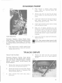
Charge Pump . . . . .
Remove Charge Pump
Install Charge Pump
40 - 41
40 - 41
41
Track Drive. . . . . .
Remove Track Drive Shaft
I nstall Track Drive Shaft .
41 - 43
41 - 42
42 - 43
Track . . . . . .
General
Remove Track.
Install Track
43 - 44
43
43 - 44
44
SETTING UP INSTRUCTIONS
NOTE: To aid in centering front arm with
ounting holes in tunnel, position skid frame
angle to bottom of tunnel.
Install Skid Frame
Equipment Necessary: Torque Wrench, Cardboard,
Rubber Mallet, Four 3/8-lnch Lock Washers, Four
3/8 x 1-1/4-lnch Bolts, 1/2-lnch Wrench, 1/2-lnch
Socket, and 9/16-lnch Socket.
1.
2.
3.
5.
Push skid frame, track and tunnel together;
then tip snowmobile onto opposite side. Use
cardboard to protect against scratching.
Clear a 12 foot by 12 foot area in set up area
of the shop.
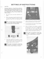
6.
Secure front mounting arm, following directions in step 4. TO NOT TIGHTEN.
Remove all mounting hardware holding the
snowmobile to the pallet. Lift the snowmobile off the pallet and set it on the floor.
7.
Move rear mounting arm of skid frame into
position with rear mounting holes in tunnel.
Slide lock washer onto bolt and secure skid
frame to tunnel, Fig. 2. DO NOT TIGHTEN
BOLT - THREAD IN ONLY HALF WAY.
Tip the snowmobile onto its side, using
cardboard to protect against scratching.
Fig. 2
•
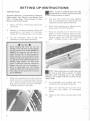
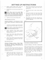
CAUTION.
Before installing skid frame, the rear arm
assembly of the skid frame must be checked.
On VIP's between serial number 4003380 and
4003585, the wrong arm may have been installed. On these VIP's the shock absorber will
bottom out before the arm contacts the bumper pads. This will cause additional stress on the
rear springs and could possibly damage the arm
assembly, shock absorber, and lower shock
mount. To check for correct arm, measure the
distance from outer end of arm assembly to
center of spring guide loop. This distance
should be 2-9/16 inch. If the distance is 2-3/4
inch, replace the arm with correct arm (Arctic
part no. 0104-192).
4.
Fig. 1
Move front mounting arm of skid frame into
position with front mounting holes in tunnel,
Fig. 1. Slide lock washer onto bolt and secure
skid frame to tunnel. DO NOT TIGHTEN THREAD IN ONLY HALFWAY.
NOTE: Rear mounting arm of skid frame may
not line up with holes in tunnel. To obtain
alignment, drive mounting arm in the required
direction until it aligns with hole in tunnel, using a
rubber mallet.
8.
Tip snowmobile onto opposite side, using
cardboard to protect against scratching.
9.
Secure rear mounting arm to tunnel with a
bolt and a lock washer. Tip snowmobile
upright.
10. Tighten all skid frame mounting bolts to 35
ft-Ib.
2
SETTING UP INSTRUCTIONS
Fig. 4
Install Skis
Equipment Necessary: Torque Wrench, Cardboard,
Low- Temperature Grease, Shock Absorbers, Long
Sleeves, Short Sleeves, Plastic Bushings, Two 7/16
x 2-1/4-lnch Bolts, Two 7/16 x 3-1/4-lnch Bolts,
Four 7/16-:'lnch Lock Nuts, 9/16-lnch Socket, and
5/8-lnch Wrench.
1.
Set the two skis and shock absorbers on a
bench.
2.
Slide a long sleeve through the stationary end
of one shock absorber and place a plastic
bushing on each end on the long sleeve, Fig.
3.
NOTE: Flat end surface of plastic bushing is
to contact shock absorber; radiused end surface is to contact shock mounting bracket.
4.
Install remaining shock absorber on other ski,
following directions given in steps 2 and 3.
5.
Tip snowmobile onto its side, using cardboard
to protect against scratching.
6.
Place ski assembly into position on spindle
and secure with a bolt, Fig. 5. Threaded hole
in ski saddle is to be to the inside, and
therefore, the bolt must be started from the
outside. Tighten the bolt to 30 ft-Ib. Thread
lock nut onto bolt and tighten to 30 ft-Ib.
Fig. 3
Bushing
NOTE: Apply low-temperature grease (Texaco 2346 or equivalent) to non-threaded
portion of bolt to prevent binding or corrosion.
Fig. 5
~
Long Sleeve
3.
Place shock assembly into position in shock
mounting bracket and secure with bolt and
lock nut, Fig. 4. Bolt is to be started from
outside. Tighten the bolt to 50 ft-Ib.
NOTE: Apply low-temperature grease (Texco 2346 EP or equivalent) to non-threaded
portion of bolt to prevent binding or corrosion.
3
SETTING UP INSTRUCTIONS
7.
Slide a short sleeve through moveable end of
shock absorber; then position the end in the
spindle mounting bracket. Secure with bolt
and lock nut, making sure bolt is started from
the outside. Tighten to 50 ft-Ib.
8.
Tip snowmobile on its opposite side, using
cardboard to protect against scratching. Install remaining ski assembly to ski spindle,
following directions in steps 6 and 7.
9.
Position snowmobile upright.
Fig. 6
Align Skis
Equipment Necessary: Tape Measure, Torque
Wrench, 9/16-lnch Wrench, 9/16-lnch Socket, and
8-lnch Extension.
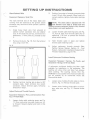
2.
Position skis straight forward and establish a
parallel relationship, Fig. 7.
3.
Measure the distance between skis, using a
tape measure. Make sure measurement is
taken behind front spring mounting bracket
and ahead of rear spring mounting bracket,
Fig . 7. Skis are to be parallel (same measurement at front and rear) or have a maximum of
1/4 -inch "toe-in" (front measurement
1/4-inch less than rear).
A
WARNING
On VI P's prior to serial number 4002777, there
is a possibility that the spindle arms were
installed incorrectly. This will cause a problem
when aligning skis and can allow the steering
post to go over center when turning hard. This
could result in injury to the operator and
passenger. All machines must be checked. When
installed correctly, the rear end of the spindle
arm will point inward about 4·1 /2 degrees when
the skis are straight. If the spindle arm points
outward 4·1/2 degrees, remove the arm, turn it
over and reinstall. Disregard the "L" or "R"
cast onto the arm.
1.
Open hood. Remove cap screw and lock nut
securing tie rod to spindle arm, Fig. 6 (with
chain case removed). Separate tie rod from
,spindle arm. Perform this operation also on
opposite tie rod end.
NOTE: Because of limited working room on
the PTa side, a 9/16-inch offset end wrench
a 9/16-inch wrench must be used to remove
the cap screw and lock nut securing tie rod to
spindle arm ~
4
Fig. 7
SETTING UP INSTRUCTIONS
4.
Position handlebar straight forward in relation
to skis.
5.
Rotate tie rod until tie rod end mounting hole
aligns with hole in spindle arm, see Fig. 6
(with chain case removed). Secure tie rod end
to spindle with a cap screw and lock nut.
Tighten cap screw to 35 ft-Ib.
Fig. 8
NOTE: Because of limited working room on
the PTa side, a 9/16-inch offset end wrench
an a 9/16-inch wrench must be used to install the
cap screw and lock nut which secure tie rod end to
spindle arm.
6.
Bottom jam nut against tie rod.
7.
Repeat steps 5 and 6 on remaining tie rod.
/!\
5.
Working from side to side, install remaining
Phillips screws. DO NOT TIGHTEN SCREWS.
6.
When all screws are installed and windshield is
in place, tighten all screws, working from the
center to the outside.
/'!\
WARNING
To ensure the utmost safety of the operator, all
cap screws, lock nuts, jam nuts, tie rods, and tie
rod ends must be tightened correctly and be
free of noticeable damage. Tie rod end must be
threaded half way into tie rod to assure
maximum steering linkage strength. If any of
these conditions is neglected, or if parts are
damaged or incorrectly assembled, serious injury to the operator or passenger may result.
Install Windshield
Check Hood Latches
Equipment Necessary: Phillips Screwdriver Having
a No.2 Blade, 11/32-lnch Wrench, and 3/8-lnch
Wrench
1.
Open hood. Allow hood to rest on the latch
strike, Fig. 9.
2.
Examine the alignment between the latch
strike and the cut out in bottom of hood
latch. The latch strike is to be positioned
directly over the cutout in bottom of hood
latch, Fig. 9. If correct alignment is evident,
proceed to step 4. If correct alignment is not
evident, proceed to step 3.
3.
Loosen the 4 lock nuts and Phillips machine
screws securing the hood latch, Fig. 9. Proceed to step 4.
4.
Close hood. Push down on each side of the
hood to determine how much "free-play"
exists between hood latch and latch strike.
Virtually no "free-play" is to be evident. If
"free-play" is evident, proceed to step 5. If no
"free-play" is evident, proceed to step 6.
5.
Loosen the 2 carriage bolts and lock nuts
securing the latch strike, Fig. 9. If hood is too
tight and is difficult to open, move the latch
Equipment Necessary: Windshield Trim, 8 Rubber
Well-Nuts, 8 Phillips Screws, and Phillips Screwdriver Having a No.2 Blade.
1.
Remove windshield from plastic bag. Dispose
of plastic bag.
2.
Separate windshield and trim by removing
three twist-lock ties.
3.
Push the 8 rubber well-nuts into mounting
holes in hood.
4.
Position windshield and trim on hood and
secure with 2 Phillips screws on each side of
center, Fig. 8. Thread screws 3/4 of the way
in. DO NOT TIGHTEN SCREWS.
5
SETTING UP INSTRUCTIONS
strike up. Proper adjustment is when hood is
tightly secured (no "free-play") and opening
and clos.ing is possible without undue binding
of hood latch and latch strike. When correct
adjustment is obtained, tighten the 2 carriage
bolts and lock nuts.
Fig. 10
Fig. 9
3.
Rotate the two adjusting screws counterclockwise 3/4 turn.
NOTE: Adjusting screws must be adjusted
evenly to prevent accelerated brake wear.
4.
6.
Close hood and check again for correct
operation.
Having
a
NOTE: Before brake can be adjusted correctly, check to ensure that brake disc is free to
move on track drive shaft. Brake disc must be free
on shaft to allow centering between brake pads and
allow maximum efficiency of the brake.
1.
Disconnect brake cable from brake unit by
loosening the brake adjusting flange nuts on
top and bottom side of brake cover, Fig. 10.
2.
Alternately tighten the two large adjusting
screws until both screws are bottomed out
(when brake pads are against disc), Fig. 10.
6
Tighten brake cable jam nut.
Install New Sealing Washer and Adjust Chain
Tension
Adjust Brake
Equipment Necessary: Screwdriver
7/16-lnch Blade, 1/2-lnch Wrench.
5.
Connect brake cable to brake unit. Squeeze
the brake lever. When brake is fully engaged,
there is to be from 1/2 to 3/4 inch between
the front of the brake lever and the brake
lever stop. If distance is not with in specifications, rotate the two adjusting nuts clockwise
or counterclockwise until the specified adjustment is obtained.
Equipment Necessary: 1/2-lnch Wrench
1.
Elevate front of snowmobile so the fluid level
in chain case is below chain tightener bolt
hole.
2.
Loosen jam nut and remove the chain tensioner bolt, Fig. 11.
Fig. 11
)
-
SETTING UP INSTRUCTIONS
3.
Replace existing sealing washer with new
sealing washer (Arctic Part No. 0107-387).
4.
Reinstall bolt into chain case and adjust chain
tension.
NOTE: Chain must be very tight. When
tightening chain tension, watch the rubber
mount at rear of converter dropcase. When the
rubber mount starts to compress, stop tightening
tensioner bolt and back bolt out about 1/2 turn.
5.
Tighten jam nut on chain tensioner bolt.
2.
When plug is removed from cover, drill a hole
in the center of plug, using a drill with a
9/16-inch bit.
3.
Tap plug into place in cover, using a rubber
mallet.
4.
Remove the present vent hose plug w/hose
and insert it in the new hole in chain case
cover. Tap into place, using a rubber mallet.
See Fig. 12.
5.
Plug original vent hole with a plug (Part No.
0109-578), see Fig. 12, and a rubber bushing
(Part No. 0109-413).
Adjust Suspension and Track
Equipment Necessary: Low-Temperature Grease
(Texaco 2346 or Equivalent), Flexible Hose Grease
Gun
1.
Fig. 12
Lubricate rear suspension arms with low-temperature grease (Texaco 2346 or equivalent).
NOTE: Position of grease fitting requires that
a flexible hose grease gun be used.
c
2.
Adjust suspension (See: Panther Service
Manual, Section VI - Suspension, Suspension
Adjustment, page VI-17).
3.
Adjust track tension (See: Panther Service
Manual, Section VI - Suspension, Track Tension, page VI-16).
4.
Adjust track alignment (See: Panther Service
Manual, Section VI - Suspension, Track Alignment, page VI-16,17).
Install New
Plug
Move Chain Case Vent
Equipment Necessary: Hammer, Rubber Mallet,
Plug (Part No. 0109-578), Rubber Bushing, (Part
No. 0109-413), Drill Having a 9/16-lnch Bit, and
1/2-lnch Cold Chisel
It has been found through extensive testing that
relocating the chain case vent will eliminate the
chance of torque converter fluid being blown out
through the vent hose.
1.
Remove the plug insert
chain case cover using
1/2-inch cold chisel. Use
plug insert until it can
cover.
in the front of the
a hammer and a
the chisel to rotate
be removed from
Check Battery and Battery Hold-Down
Equipment Necessary: Drill With a 3/16-lnch Bit
When removing the battery to charge (fill) during
pre-delivery, battery case must be checked for
cracks and excessive warping. All damaged batteries must be replaced. The cracks or warping may be
caused by too tight a battery hold-down. To
correct this, new holes must be drilled in
hold-down bracket.
1.
Remove the battery hold-down by releasing
the two latches, Fig. 13. If tension seems too
tight, latches must be relocated. See steps 5-7.
7
SETTING UP INSTRUCTIONS
Fig. 13
NOTE: If the snowmobile is to be operated
over prolonged periods with the lights ON, or
if the snowmobile is stopped and started quite
often, the battery charge may become low. A very
convenient accessory, called a Sta-Charge, is available through the local Arctic Cat snowmobile
dealer. The Sta-Charge is a snowmobile mounted
battery charger that can be plugged into any 115
volt AC outlet to charge the battery.
Change Battery Ground
Equipment Necessary: Torque Wrench, Screwdriver Having a 5/16-1nch Blade, 10mm Wrench,
13mm Wrench, and a 13mm Socket.
2.
Remove the battery; then examine battery for
cracks or excessive warpage. If battery is
cracked or warped, replace.
3.
Fill battery with electrolyte to the proper
level.
1.
Remove the negative battery cable (black)
from the chassis ground.
4.
Fully charge battery (See: Panther Service
Manual, Section IV - Electrical System, Battery Charge Table, page IV-33).
2.
Loosen opposite end of the negative battery
cable on the battery.
3.
Remove the top torque converter case assembly bolt, Fig. 15.
5.
It is recommended that the battery ground wire be
relocated during set-up.
Remove latches from the hold-down.
)
Fig. 15
6.
Drill four new 3/16-inch holes 1/4 inch lower
than original holes, using a drill with a
3/16-inch bit, Fig. 14.
Fig. 14
,,
(
n
(
(
;,:?
~~' ·'I
(. ( J
"'"
0'
<)
0
0
Remove both latches.
Drill two 3/16" holes 1/ 4 " lower.
7.
Reinstall latches.
8.
Install battery in battery pan.
9.
Secure in place with battery hold-down.
8
4.
Fasten open end of negative cable to top
torque converter case assembly bolt. Tighten
to 16 ft-Ib.
5.
Secure negative cable to battery terminal.
)
SETTING UP INSTRUCTIONS
2.
Check Solenoid Wire
Equipment Necessary: Small File
The male terminal end of the heavy black wire
running from the solenoid to the ignition switch
connector may have burrs which prevent a positive
connection.
1.
Grasp heavy black wire from solenoid at
ignition switch connector end and slightly
pull. If wire does not pull out, terminal end is
satisfactory. If wire pulls out, proceed to step
NOTE: The choke cable is adjusted with 1/8
inch between front edge of choke knob and
console to ensure carburetor choke is fully forward
when choke is not used (pushed in).
3.
Loosen throttle cable retaining screw, see Fig.
17. Pull all slack from throttle cable plus an
additional 1/16 inch to preload the throttle
safety switch spring.
4.
Hold throttle cable in place and tighten
throttle cable retaining screw.
5.
Adj ust carburetor th rottle controls (See:
Panther Service Manual, Section III - Fuel
System, Carburetor I nstallation/Adj ustments,
Th rottle Adj ustment, page 111-19).
2.
2.
Remove the burrs, Fig. 16, from the termi nal
end, using a small file.
Fig. 16
Position front edge of console-mounted choke
knob 1/8 inch from console. When knob is in
correct position, tighten choke cable retaining
screw.
,...-----..--- File off.
Install Carburetor Enrichener Bushing
Equipment Necessary: Hammer, Pin Punch, and
Screwdriver Having a 5/16-lnch Blade
INCORRECT
3.
CORRECT
Position terminal locking tab at about a 45 0
outward angle. Insert terminal into switch
connector. Check terminal again, following
directions in step 1.
Adjust Choke and Throttle Controls
A carburetor enrichener bushing has been made
available for installation in the carburetor. The
bushing will allow richer and faster fuel delivery
when starting. The bushing (Arctic Part No.
0109-623) is not supplied with the snowmobile but
can be ordered by an authorized Arctic Cat
Snowmobile dealer.
1.
Loosen screw holding throttle cable to throttle arm, Fig. 17. Remove throttle cable.
2.
Loosen screw holding choke cable to enrichener valve arm, see Fig. 17. Remove choke
cable.
Equipment Necessary: Pliers, and Screwdriver Having a 1/4-lnch Blade
1.
{...-
Loosen choke cable retaining screw, see Fig.
17. Move carburetor-mounted choke arm fully forward (toward engine) and hold in this
position.
'-
9
SETTING UP INSTRUCTIONS
Fig. 17
6.
Lubricate enrichener valve and reinstall in
carburetor body. Tighten the four screws at
top of carburetor.
7.
Secure choke cable to enrichener valve.
8.
Install throttle cable in throttle arm. Remove
all slack from throttle wire; then pull through
an additional 1/16 inch of the throttle wire.
This will preload the throttle safety switch.
Secure throttle cable in throttle arm by
tightening retaining screw.
Check Oil Injection
Equipment Necessary: 10mm Wrench
3.
Loosen the four screws on top of carburetor
until fuel pump assembly and throttle bracket
can be raised to allow enrichener valve to be
removed from carburetor body.
4.
Slide enrichener valve out of carburetor body,
using extreme care so small spring and retainer ball are not lost.
5.
I nstall bushing (Arctic Part No. 0109-623)
through large side hole into air bleed hole,
small end first. Seat bushing even with edge of
large side hole with a pin punch, Fig. 18.
1.
Fill oil reservoir
ject-a-Lube Oil.
with
Arctic
VIP
In-
2.
Loosen air bleed bolt located just below
pump inlet tube on PTO side of injector
pump, Fig. 19.
Fig. 19
Fig. 18
10
3.
Note clear plastic oil tube running from oil
reservoir to oil injector pump. Allow oil to
flow out air bleed hole. When clear plastic
tube shows no trace of air, tighten air bleed
bolt.
4.
Mix one gallon of gas with oil in a 20: 1
mixture. Add mixture to the gas tank.
J
SETTING UP INSTRUCTIONS
5.
Start the engine. In a short time, excessive
smoke will indicate the pump is' working.
Then, add regular gas (without oil) to fill fuel
tank.
3.
NOTE: This will dilute the rich fuel/oil
mixture in the fuel tank.
Set Ignition Timing
Start engine and check ignition timing, using a
timing light. (See: Panther Service Manual,
Section IV - Electrical System, Check Ignition
Timing, page IVA1).
Equipment Necessary: Torque Wrench, Timing
Light, Quik-Jak, Screwdriver Having a 1/4-lnch
Blade, and a 10mm Socket
Check Switch Operation
Equipment Necessary: No Special Tools Required
c
1.
Raise , rear of snowmobile off the shop floor,
using a Quik-Jak. Make sure track is free to
rotate.
2.
Turn ignition key to START position and
start the engine.
3.
Point timing light at timing mark on fan
housing and note position of timing mark on
flywheel.
Accelerate engine to 6000 rpm. Timing marks
on flywheel and fan housing should align.
1.
Turn ignition switch to START position and
start engine.
2.
With engine running, move light switch to ON
position; headlight and taillight are to illuminate.
3.
Move headlight dimmer switch to other position; headlight beam should change.
4.
Squeeze brake lever; brakelight is to illuminate.
4.
5.
Move throttle safety/kill switch to either OFF
position. Engine will stop if switch is operating properly.
NOTE: Make sure timing mark advances as
rpm is increased. Built in electronic advance
cannot be adjusted.
6.
With engine running, rotate ignition key to
OFF position to ensure ignition switch will
shut engine off.
5.
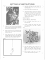
Time The Engine (Ignition)
Equipment Necessary: Torque
13/16-lnch Spark Plug Socket
Wrench,
1.
6.
6.
Stop Engine - To adjust ignition timing,
magneto base assembly must be rotated either
clockwise or counterclockwise.
7.
Remove the three bolts securing recoil assembly to ·fan housing, Fig. 20. Set recoil
aside.
and
It is recommended that the ignition timing be
checked at time of "set-up" and each time the
engine is serviced . Incorrect ignition timing has a
negative effect on engine performance.
If timing marks align at 6000 rpm, timing is
correct. If marks do not align, proceed to step
Fig. 20
Disconnect high tension wire from spark plug.
Remove spark plug and washer. Check for
correct type and heat range (Champion
N-19V).
NOTE: The Arctic Cat VIP Snowmobile has a
surface gap spark plug. No gap can be set as in
conventional plugs.
2.
Install spark plug and washer and tighten to
16-18 ft-Ib.
11
SETTING UP INSTRUCTIONS
8.
Remove the three lock washers and nuts
securing auxiliary starting pulley, Fig. 21.
Remove the large plate, auxiliary starting
pulley, and pump drive pulley.
Fig. 21
Adjust Headlight
Equipment Necessary: (See: Panther Service
Manual, Section IV - Electrical System, Headlight
Adjustment)
1.
The headlight is to be adjusted for vertical
and horizontal aim of the high/low beam
(See: Panther Service Manual, Section IV Electrical System, Headlight Adjustment,
page IV-42) .
Change Brakelight Wiring
Equipment Necessary: 6-lnch Piece of 16 Gauge
Wire, One Insulated Wire Connector, One Female
Terminal (Part No. 0109-195)
9.
10.
Remove the three bolts securing fan drive
pulley to flywheel. Remove the pulley.
Rotate flywheel until magneto base plate
screws can be seen. Loosen the two screws.
Rotate base plate clockwise to advance the
timing.
NOTE: If timing mark on flywheel was ahead
of reference mark, rotate base plate clockwise. By contrast, if flywheel mark was behind
reference mark, rotate base plate counterclockwise.
To prevent dimming of headlights when brake is
applied, it is recommended that the brakelight be
converted from ac to dc operation.
1.
Cut red wire running from light switch to
brakelight harness connector, using a side
cutter.
2.
I nstall a female terminal on one end of the
6-inch piece of 16 gauge wire.
3.
Connect remaining end of 6-inch wire to red
wire (cut in step 1) running to the brakelight
harness connector. Tape end of red wire not
being used.
4.
Remove connector plug from back of ignition
switch. Insert end of new wire into remaining
open terminal hole in connector plug.
5.
Plug connector into back of ignition switch.
6.
Turn ignition switch to ON position. Squeeze
brake lever. Brakelights should illuminate.
)
11. Tighten magneto base plate attaching screws.
12.
13.
Place axial fan belt on fan pulley and position
on flywheel. Secure with three bolts and lock
washers. Tighten bolts to 5 ft-Ib.
Install in order, the pump drive pulley, pump
belt, auxiliary starting pulley, and the large
plate on the three studs of the fan drive
pulley. Secure with ' three nuts and lock
washers; then tighten to 5 ft -Ib.
14. Start engine and check timing (step 3 to 5). If
timing is correct, install recoil starter on fan
housing. Secure with three bolts and lock
washers; then tighten bolts to 5 ft-Ib.
NOTE: If brakelights do not work, go back
and check all connections or check brakelights (See: Panther Service Manual, Section IV Electrical System, Check Brakelights, page IV-25).
7.
Turn ignition switch to OFF position.
}
12
-
BREAK-IN
Strict adherence to the following break-in procedure will contribute to optimum performance
and longevity of the Arctic Cat snowmobile engine.
I nform the customer that for the first 10 operating
hours, the engine is not to be subjected to heavy
load conditions or full throttle operation. During
the initial break -in or just after the engine is
overhauled, a maximum of 1/2 throttle is recommended. Operating speeds are to be varied and not
maintained for a prolonged time.
NOTE: During break-in or after the engine is
auled, one gallon ONLY of a 20:1
mixture (fuel:oil) should be used to help lubricate
engine until excessive smoke indicates the injection
pump is working.
After the customer operates his snowmobile for 10
hours (break-in), ask him to return the snowmobile
to the dealership for a 10 hour maintenance check.
This checkup, however, is at the expense of the
snowmobile owner. The checkup will allow the
dealer to talk with the customer and determine if
any serious problems exist. If there are any
problems, they may be easier to remedy at this
time rather than to allow the snowmobile to be
operated at the risk of further complications. If a
defective part is found during the ten hour
checkup and it is a warrantable part, submit a
warranty claim form through normal Arctic
channels (refer to the Warranty Policy and
Procedure Booklet). The customer is not to pay for
a warrantable part.
Arctic recommends that specific items be checked
at the ten hour checkup. The specific items are
critical adj ustments, operati ng characteristics, and
safety features (See: Ten Hour Checkup, page 13).
TEN HOUR CHECKUP
Arctic recommends that specific items be checked
after the snowmobile has been operated in accordance with the break-in procedure described in the
Operator's Manual. The cost of the checkup is to
be assumed by the customer. This ten hour
checkup will allow the Arctic dealer to talk with
the customer and determine if a problem exists. If
the customer is dissatisfied, the problem may be
easier to remedy at this time rather than to allow
the snowmobile to be operated until a possible
failure occurs. If a defective part is found and it is
a warrantable part, submit a warranty claim form
through normal Arctic channels (refer to the
Warranty Policy and Procedures Booklet).
4.
Remove the spark plug and examine the
center electrode. Determine the engine operating temperature by examining the color of
the center electrode.
5.
Check the fuel line, the in-line fuel filter, and
the fuel tank filter.
6.
Check the carburetor for proper adjustment.
7.
Check the choke and throttle cables. Cables
must not be bent, frayed, or kinked.
8.
Check the skags and ski alignment.
9.
Check the fluid level in the dropcase.
10.
Check the condition of the oil pump drive
belt.
The following items are to be checked:
1.
2.
3.
Ask the customer if he is generally satisfied
with the performance and operating characteristics of the snowmobile.
Check the operation of the ignition switch,
headlight and taillight switch, brakelight
switch, and the emergency shut-off switch.
Make sure both high and low beams of the
headlight work.
Test drive the snowmobile so that you can be
certain all systems are working properly. Test
the brake for proper braking characteristics.
11. Check all vent holes for obstructions and vent
lines for kinks.
12.
Check track tension and alignment.
13.
Lubricate rear suspension arms.
14. Check ignition timing.
15. Tighten all nuts and bolts.
16. Tighten the intake, exhaust and recoil hardware to the correct torque value.
17.
Make sure all safety decals are in place.
18. Test drive the snowmobile.
19. Clean the snowmobile prior to customer
pick-up or delivery.
13
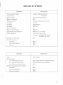
ELECTRICAL SYSTEM
Using the VIP electrical specifications given below,
refer to instructions provided in the Panther
Service Manual for electrical systems testing (see
Description
Arctic PIN
Panther Service Manual, Section IV, Electrical
System, Before Trouble Shooting Ign . System,
page IV-20 and following).
Test Value
Tester Connections
OHMMETER TESTING
Ignition Coil:
Primary
Secondary
Exciter Coil
Pulser Coil
Lighting Coil
3001-350
3001 -350
3001 -129
3001-130
3001 -338
.036 ohms
680 ohms
295 ohms
225 ohms
.18 ohms
+to
+to
+to
+to
+to
blue
high tension #1
red
red
yellow
- To brown (ground)
- to high tension #2
-to ground
- to white
- to yellow
OUTPUT TEST WITH ELECTRO SPECIALTIES COl TESTER MODEL NO.1
(Note: Red lead is positive, yellow lead is negative.)
Ignition Coil
Exciter Co il
Pulser Coil
COl Unit
3001-350
3001 -129
3001-130
3001-346
70
50
50
75
+to
+to
+to
+to
ground
ground
ground
brown COl lead
-to
- to
-to
-to
high tensio n
red from stator
white from stator
blue CD I lead
Ground second
Blue COl lead
VOLTMETER TEST
Circuit Board
12-15 DC volts
+to AC terminal
-to ground terminal
•
CAUTION.
The above measurement is for regulated voltage
at from 2000 to 6500 engine rpm. Unregulated
voltage measured at the two yellow leads in the
main engine connector plug will vary considerably with engine rpm. Caution should be used
when measuring this voltage as it may rise as
high as several hundred volts. A low capacity
voltmeter may be damaged.
AMMETER TEST
Alternator
7 amps*
+to yellow/black
*Output at 6500 rpm with all lights on and battery discharged.
NOTE: Unless otherwise specified, all test values have a tolerance of ±10%.
14
-to circuit board diode
I.l')
p -STOP '""TeN
BI.K
BLK
.------------------------------------------------------------ BLK ----------~
,--------- YEI..
BI.K~---
(
~
w
------------.1
(Sr. £. !\lOTE. 3 )
(
'i'~---=~l-------,
YEI.
I-
BU:
en
>
en
RED
f:'eD
')
...I
<I:
-I-a:
CJ
')
BU----='>l----'>'1---- - - '
8lK
eEO
BRRU
CJ
~1
TIIIL I.IOHTS
BLK
LIOHTSf
W
8/iTTEf:'Y-
...I
W
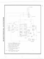
4.
E I0£d,/I\J£ GROUII'lO PD/A)TOII) BRIIKE A55EMI3LY SIlDULD BE.
FILED TO INlPkOUE CDlUT7IlC/, OR GmUfI.)D SHOUD l3E.
CHIlI\'CEO TO A O/FFEREA)T FrJ/10T 010 CHIISS/S .
3
RUf)/{)MUJDW MOD/F/CAIlOII) Tf) PREUEI\lT OIMM/rJG
OF H£IIDLI(!'HTS WHEIIJ BRIN<E 15 APPLIED
2. TElVlPEel1TOeE (;110G£ 1./(3/(TS: CONNECT ONE wle£
TO LlCHTS liND ONe WI.t'E TO GeOOND
ON Clf:'UIT BOIII?D
NOTe: I TIiCHOIVlETEf:' /lNO SPEEDOIJ/IETEf:' I./GHTS LONNaT
TO LIGHT lCRlYJlNIlL cr c/ICLUIT BOIIPD.
l)-,
\
~'"- ~~
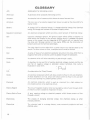
GLOSSARY
A.C.
Abbreviation for alternating current.
Alternator
A generator which produces alternating current.
Amperes
An electrical unit of measure which shows the rate of current flow.
Armature
The iron core of an electro-magnet; best known as used as the drive shaft of a
starter motor.
Battery
A storage cell for electrical energy. It changes electrical energy into chemical
energy for storage and reverses the process to supply power.
Capacitor (condenser)
An electrical component which can store a small amount of electrical energy.
CDI
Capacitor Discharge Ignition. An ignition system which utilizes a capacitor to
store exciter coil output for the primary ignition circuit. It releases this stored
energy at the proper time by triggering an SCR switch with an impulse from
the pulse coil. Stronger ignition at low engine RPMs and the elimination of
breaker points are the foremost advantages.
Circuit
The path electric current takes from a power source to a lead and back to the
source. To allow current to flow, a complete circuit must be formed.
Coil
A series of loops of an electrical conductor around an iron core, which form a
magnetic field when an electric current is passed through the conductor.
Conductor
A substance which will allow electricity to pass through it easily.
Cycle
It describes the rise and fall of positive electrical voltage, reversal, and the rise
and fall of negative voltage at alternator output terminals. One cycle is
illustrated in wave form.
D.C.
An abbreviation for Direct Current.
Diode
An electrical component which will allow current to flow in only one direction.
A diode installed in an A.C. circuit will allow current to flow in only one half
of the cycle resulting in a pulsating dir~ct current.
Electrode
An electrical conductor which is used as a terminal for a high resistant or
non-metalic portion of an electrical circuit.
Electro-Magnet
The core of magnetic material (iron) surrounded by coils of wire through which
an electric current is passed to magnetize the core.
Electro-Motive Force
A term meaning voltage or electrical pressure which forces current to flow
through a circuit.
Electrolysis
The process of changing electrical energy into chemical energy, as when
charging a battery.
Electrolyte
The chemical used
distilled water.
In
a storage battery; most commonly sulphuric acid and
./
16
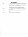
GLOSSARY
t-
c
Exciter
An induction coil used to produce electrical energy for the primary circuit of
an ignition coil.
Farad
The unit of measure used to determine the amount of electrical energy which
can be stored in a capacitor. The unit used in ignition systems is the
micro-farad.
Field
The magnetic lines of force surrounding a magnet. In electrical motors, the
electro-magnetic coils mounted in fixed positions in the case provide a field
which attracts the armature. These coils are referred to as field coils.
Generator
A device that produces electricity by moving a conductor through a magnetic
field, thus mechanical energy is changed into electrical energy.
Ground
A term used in referring to a common conductor, used as part of an electrical
circuit. The chassis of a snowmobile is an example.
Ignition
The electrical arc used to start the burn of combustible fuel in an engine. This
arc is produced by applying high voltage to the spark plug.
Induction
The process of generating electrical energy in a conductor by causing the
conductor to intersect magnetic lines of force. This can be done by moving the
conductor through a magnetic field, as in a magneto alternator, or by building
and collapsing a magnetic field around a conductor. This second method is used
in transformers or in an ignition coil.
Load
An electrical component or series of components requiring electrical energy for
operation. The unit of measure is watts. The load on a snowmobile would be
the lights, tachometer and the charge requirements of the battery. On the VIP
this will total nearly 100 watts.
Magnet
A body which attracts ferrous materials, such as Iron, and is surrounded by
magnetic lines of force.
.f
Magneto
A generator wh ich uses permanent magnets for its field.
Ohms
A unit of measure used for the ability to resist the conducting of electricity.
Parallel
The method of connecting an electrical load component to a power source by
attaching leads directly to the output terminals, positive to positive and
negative to negative.
Polarity
The description of positive or negative poles of a magnet or an electrical circuit.
Primary
As referred to in ignition coils it is the low resistance winding of the coil to
which exciter voltage is applied. The primary winding induces the high voltage
in the secondary.
Rectifier
An electrical component which will allow current to flow in only one direction.
SCR
Silicone Controlled Rectifier. A device which will not conduct electric current
until a given voltage is applied to it. It acts as a gate until enough voltage is
applied to the triggering component; it then conducts very well .
17
GLOSSARY
Series
A method of connecting electrical components which requires the current from
the power source to flow through all the components before returning. The
leads of the components are connected in this manner, the positive lead of a
component is attached to the negative lead from the preceding component. The
first and last lead are then connected to the power source.
Secondary
As referred to in the ignition coil, it is the high resistance circuit, which
produces the high voltage required to arc across the spark plug electrodes.
Solenoid
A cylindrical electro-magnet with a moveable iron core. In the electric start
system the core closes a heavy duty switch to carry the high amperage required
by the starter motor.
Volts
The unit of measure used for the amount of electrical pressure from a power
source.
Watts
The unit of measure for a quantity of electrical energy.
J
)
18
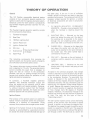
THEORY OF OPERATION
General
The VI P Panther snowmobile electrical system
consists of two, somewhat separate systems; the
ignition system and the magneto alternator system.
Electrical current for both systems is produced by
the flywheel magneto generator assembly (12 volt,
100 watts).
the spark plug. If the arc is not of sufficient
Voltage, ignition will be poor and result in less than
optimum performance. To produce and control the
necessary voltage required for ignition, a number
of electrical components are used in conjunction
with each other.
1.
FLYWHEEL-MOUNTED PERMANENT
MAGNETS - Provide a moving magnetic field
when the flywheel is rotating around the
coils.
2.
EXCITI NG COl L - Mounted on the base
plate, just below the pulser coil. One lead of
the exciting coil is grounded to the engine,
through the coil attaching screws, and the
other lead (red) is connected to the COl unit.
3.
PULSER COl L - Mounted on the base plate
just above the exciter coil, one lead of the
pulser coil is attached to the same red lead as
the exciter coil. The other (white) lead is
connected to the COl unit.
4.
COl UN IT - Mounted on the coil bracket, it
contains a rectifier, capacitor, and a solid state
switch.
5.
IGNITION COl L - Mounted on the coil
bracket with a high tension lead going to both
spark plugs.
The flywheel magneto generator assembly consists
of the components listed below.
1.
Flywheel w/magnets
2.
Base Plate
3.
100 Watt Lighting Coil
4.
Ignition Pulser Coil
5.
Ignition Exciter Coil
6.
COl Unit
7.
External Coil
8.
Spark Plugs
I
Mounted Externally
on Engine
The remaining components that comprise the
ignition system are: the ignition switch, emergency
shut-off switch and throttle safety switch.
The magneto alternator system produces 100 watts
and is regulated at 12 volts. The generated electric
current provides the spark that is necessary to
ignite the fuel air mixture in the combustion
chamber, and also, by passing through the wiring
harness and switches allows for operation of the
I ights and electrical accessories.
In summary, a flywheel magneto generator
assembly that produces maximum output will
allow the engine to run smoothly, and all other
electrical systems will operate properly. Conversely, without maximum output from the flywheel
magneto generator assembly, the engine and other
electrical systems will not operate properly.
Ignition System
The function of the ignition system is to ignite the
fuel/air mixture contained within the combustion
chamber at a moment of compression (firing
moment) that produces the strongest power stroke.
(
Igniting of the fuel/air mixture in the combustion
chamber is accomplished by a generated electrical
arc across the center and side electrode (air gap) of
As stated in the previous paragraph, high voltage
current is required to jump the spark plug air gap,
which will result in ignition of the fuel/air mixture
in the combustion chamber. To accomplish this,
current is induced in the exciting coil by the
rotation of the four magnets. Since the magnets are
alternately-mounted, and also, alternately pass the
exciting coil, the magnetic forces change direction
of travel. Because the magnetic forces travel from
north to south (positive to negative), the direction
of flow changes every 90 degrees of flywheel
rotation. Therefore, the electricity induced in the
exciting coil winding will also alternate in direction
of flow. The term for this type of flow is
"alternating current".
The COl ignition system cannot utilize alternating
current, so the current from the exciter is routed
through a rectifier to eliminate the negative flow.
The positive flow passes through the rectifier and is
stored in a capacitor in the CDI unit. The capacitor
is connected to the primary winding of the ignition
coil through a SCR. The SCR acts as a switch for
19
THEORY OF OPERATION
The battery is used as a storage center and power
source for the electric start motor. To operate the
starter motor, the battery must be fully charged
for maximum output. Current for the battery
charge system is supplied by the magneto alternator system. The generated current, which is induced in the lighting coils by the rotating magnets,
is routed to the regulator/rectifier. This current is
alternating current, the type that will not charge
the battery. Therefore, for battery charging, alternating current must be changed to direct current.
Because a change from alternating current to direct
current is made within the regulator/rectifier, the
battery receives only positive charges, resulting in a
fully charged battery. When the battery is fully
charged, the regulator/rectifier routes the excess
current to ground, thus preventing damage to the
charging and lighting system.
TACHOMETER
The function of the engine tachometer is to
register the engine mainshaft revolutions per mi nute. To accomplish this, the A and Y terminals on
the back of the tachometer are connected in series
with the yellow magneto alternator output lead,
which sends pulses to the tachometer. These pulses
flow through a coil in the tachometer, creating an
electromagnetic force and producing tachometer
needle movement against a spring. As the pulse rate
of the magento generator increases, so does
tachometer needle movement. Conversely, as the
pulse rate decreases, so does the electro-magnetic
force. This allows the indicator needle spring force
to become dom inant and indicate a reduction in
RPM.
Mounted in the tachometer and connected in
parallel with the instrument lighting circuit is the
tachometer light bulb. The bulb's only function is
to illuminate the tachometer dial. It does not
affect any mechanical function.
l
TEMPERATURE GAUGE
The function of the temperature gauge is to indicate cylinder head temperatures. The principle of
thermoelectricity is used to operate the gauge.
Some metals give up electrons readily wh ile others
readily accept electrons. An increase in temperature increases this quality. Zinc and copper are metals which possess these qualities respectively. By attaching a sender unit made of both of these metals
sandwiched together to the base of the spark pi ug
and running a lead to the temperature gauge, a
circuit can be formed to allow electron flow. The
gauge is then calibrated to show a temperature
reading in relation to the electron flow.
J
22
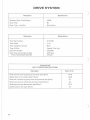
DRIVE SYSTEM
Description
Torque Converter Model
Specifications
Kawasaki Model CIA440DIA
TI8440DIA
Applied Engine
Converter Type
3 Element, 1 Stage,2 Phase
Maximum Efficiency
83%
Rotating Direction
Clockwise Facing Converter Input
Dry Weight
13-1/2Ib
Idle Speed
1500-1800 rpm
Stall Speed
5000 rpm
Stall Torque Ratio
3.0
Maximum Engine Speed
7500 rpm
Engine Speed at Coupling Point
6250 rpm or 1 to 1 Ratio
Recommended Oil
Arctic Cat Torque-a-Lube
Alternates:
Oil Capacity - Chain Case
ATF DEXRON (by GM)
M2C33E/F (by Ford)
3 qt
System Temperatures:
(
Maximum
250 0 F
Intermittent Maximum
280 0 F
Optimum
200 0 F
Specifications
Description
Filter
60 to 80 Mesh
System Pressures
Line 1 (Pump Suction Line)
Suction Head Maximum - 150mm 14-30 psi
Line 2 (Pump to Converter)
0-3 psi (At Maximum Stall Speed)
Line 3 (Converter to Chain Case)
o psi
System Temperatures (At Oil Reservoir):
Maximum
250 0 F
Intermittent Maximum
2800 F
Optimum Condition
2000 F
23
DRIVE SYSTEM
Description
Specifications
Sprocket Ratio (Drive/Driven)
19/39
Chain Pitch
96
Chain Type - Link Belt
Silent Chain
Description
Specifications
Track Part Number
0110-790
Track Width
17 in.
Track Length on Ground
36 in.
Type of Drive
I nternal Drive Lug
Cleat Part Number
0102-086
Cleat Type and Number of Solid
Rivets Holding Each Side Belt
2/3 Flared
3 Rivets
CONVERTER
BOL T TORQUE SPECI FICATIONS
Description
Value (ft-Ib)
Bolts securing input coupling and converter case (8mm)
14-16
Special lock nut on turbine shaft (12mm)
18-20
Bolts and nuts securing pump wheel and converter case (6mm)
5-7
Bolts securing pump wheel boss and pump wheel (5mm)
3-4
Bolts securing front case and rear case (8mm)
Socket bolts on rear cover (6mm)
24
12-14
5-7
DRIVE SYSTEM THEORY
r
The Cat-A-Matic drive system, with the Hydro-Dynamic Torque Converter, has characteristics different from those found in conventional centrifugal
drive clutch systems. The Cat-A-Matic transmission
has no "clutch engagement speed". Instead, it
always transmits power while the engine is running,
even at idle speeds.
L~
WARNING
ill
Since the Cat-A-Matic transmission system
transmits power whenever the engine is
running, it is extremely important that the
snowmobile never be left unattended while the
engine is running_
TORQUE CONVERTER
Fig. 22
PLUG
CASE
CASE
GAS~ ETI
~--/
COVER
SEAL
BEARING
TURBINE SH AF T
COVER
The Hydro-Dynamic Torque Converter consists of
3 independent components or members. These are
the impeller or pump wheel, which is the driving
force; the turbine, which is the driven wheel to the
applied load; and the reactor or stator, see Fig. 22.
The Hydro-Dynamic Torque Converter transmits
power solely by the dynamic action of a fluid in a
·closed recirculating path_ In operation, the impeller
driven by the engine acts as a centrifugal pump. Oil
which substantially fills the body of the converter
flows into the impeller inlet (the part nearest the
center of the wheel). It then passes outwardly
through the impeller passages and leaves at the
outer part of the pump wheel where it enters the
turbine member. In the turbine member the oil
flows inwardly through the passages to be discharged from the inner part of the wheel into the
reactor member.
25
N
en
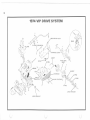
1974 VIP DRIVE SYSTEM
~
BREATHER - DIP STICK
!
r\ ~r
;~f --- _
OIL (INES ICONVERTER)
/
EN GIN E
~
~
RING
l
"\:::?,::)VJiL
__~j_~~
'~'t@/V~
:. _
b
(7
f
;~
-I
(
CHAINCASE COVER
~
GASKET
x '
TRACK DRIVE
SHAFT
.1'JrfJ~.'r"
~-.r· .' 1
S-"
~
HAINCASE
\'
RING
LOWER SPROCKET
UPPER SPROCKET
u
DRIVE SYSTEM
I t is the reactor or stator member wh ich gives the
torque converter its ability to change torque and
thereby distinguishes it from the similar but
simpler fluid coupling system. In a fluid coupling
device, torque ratio is the same for all speed ratios.
In the torque converter, the unique reactor member performs the same basic function in the fluid
circuit as the fulcrum point in a simple lever
system. The primary cause of the torque reaction
of the reactor member is the change in spin velocity
of the fluid mass around the shaft centerline
without any change in radius.
The circulation of oil between the impeller and the
turbine results from the difference in centrifugal
force developed in these two units. The impeller,
turning at the higher speed, produces a greater
centrifugal pressure difference between inlet and
outlet than is produced by the turbine. The
resulting net pressure difference from impeller
circuit to turbine circuit causes fluid flow. As the
turbine speed increases, its potential centrifugal
pressure difference increases reSUlting in a smaller
net pressure differential between impeller circuit
and turbine circuit and, therefore, a lowered
circulation rate. Since the torque transmitted is
directly related to flow rate, the impeller speed
must increase as turbine speed increases in order to
transmit a constant torque.
By mounting the reactor assembly on a one-way
clutch, the reactor remains stationary while subject
to the reversing action of the backward spinning oil
as it leaves the turbine. When the oil flow from the
turbine begins to spin forward (as the slip is
reduced between impeller and turbine wheels and
they approach un ity), the reactor is free to tu rn
with it. As the slip is further reduced, the device
acts as a fluid coupler with improved efficiency on
a one-to-one match. Without the one-way clutch,
turbine torque becomes less than impeller torque
at higher speed ratios as a result of torque reversal
on the reactor. With the one-way cI utch, the
reactor torque cannot reverse but remains zero.
When the speed ratio becomes greater than that at
the one-to-one torque condition, the reactor begins
to rotate (free wheel) in the direction of the
impeller.
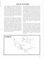
Working in conjunction with the torque converter
are the injector pump and the torque converter
charge pump. The injector pump feeds lubricating
oil into the combustion chambers. As it is belt
driven by the engine, the injector pump provides
oil in direct proportion to the speed of the engine;
more oil when the engine is turning at high speed,
less oil when the engine is idling. The charge pump
circulates filtered oil under pressure to ensure
constant efficiency of the torque converter. Also,
the charge pump provides oil cooling through
circulation.
PUMPS
~
®
PULLEY t"'J
/'
/0
NJEC"~
~ i;
O"'NG~
~
U'ES
IL INJECTION
~
~
c
..
'
,
PUMP
"~c ~
BELT GUARD
SEAL
27
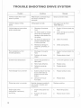
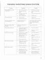
TROUBLE SHOOTING DRIVE SYSTEM
Problem
Condition
Remedy
Vehicle moves when recoil
starter is pulled.
Mechanically connected input
and output member in
converter.
Check converter inside.
Vehicle creeps at idling
speed.
Idling speed too high.
Idle speed must be from
1500-1800 rpm.
Vehicle does not move when
engine accelerated.
1.
Shortage of converter
fluid.
1.
Supply fluid and check the
level.
2.
No fluid supply by charge
pump due to mechanical
damage or belt broken for
the pump.
2.
Check charge pump and its
drive system.
3.
No fluid flow because oil
strainer covered by dust
or other particles.
3.
Clean the strainer.
4.
Mechanical damage in
converter, sprockets, or
chain.
4.
Check components.
1.
Shortage of converter
fluid.
1.
Supply fluid and check the
level.
2.
Problem with stator
wheel.
2.
Replace stator wheel.
1.
Continuing operation at
stall speed.
1.
Limit stall operation to 30
2.
Relief valve defective.
2.
Replace valve.
3.
Defective converter
clutch.
3.
Replace clutch.
1.
System pressure too high
due to relief valve or
pressure control valve
defect.
1.
Replace pressure valve.
2.
Defective O-ring or
fluid seals.
2.
Replace seals.
Poor acceleration at full
throttle operation.
Extreme fluid temperature
Fluid leakage from converter
Chattering noise in converter
Backlash between crankshaft
and coupler. Coupler worn
excessively.
Replace coupling.
Engine stalls when
snowmobile is stationary
and idling.
1.
Engine idling speed too
low.
1.
Reset idling speed.
2.
Problem with stator
wheel.
2.
Replace stator wheel.
28
-
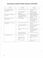
TROUBLE SHOOTING DRIVE SYSTEM
r
Problem
Poor performance and hot
charge pump
Drive chain ratchets.
Remedy
Condition
1.
Air in torque converter.
1.
Bleed torque converter.
2.
Shortage of converter
fluid.
2.
Supply fluid and check
level.
3.
Air leak on intake side
of charge pump.
3.
Check all fittings and lines.
4.
Scored charge pump.
4.
Replace pu mp.
1.
Chain too loose.
1.
Tighter chain.
2.
Broken motor mount.
2.
Install new motor mount.
Converter fluid leaks around
drive shaft bearing.
Poor seal around bearing
retainers and bolts.
Apply liberal amount of silicone
seal or bathtub seal to bolt
holes and bearing retainer
gasket.
Gasket will not seal. Chain
case cover.
Warped chain case cover or
chain case.
Replace necessary part.
Chain rattles in chain case.
1.
Chain tension improperly
adjusted - too loose.
1.
Adjust chain tension.
2.
Chain stretched beyond
adjustable limit.
2.
Install new chain and
sprockets.
1.
Chain too loose - tension
improperly adjusted.
1.
Adjust chain tension.
2.
Chain stretched beyond
adjustable limit.
2.
Install new chain and
sprockets.
3.
Sprocket teeth worn.
3.
Install new sprockets and
chain.
4.
Broken motor mount.
4.
Replace motor mount.
1.
Chain tension improperly
adjusted - too loose.
1.
Adjust chain tension.
2.
Sprocket teeth worn.
2.
Install new sprockets and
chain.
3.
Sprockets misaligned.
3.
Align sprockets.
1.
Track is misaligned.
1.
Set track tension and
alignment.
2.
Outer belts worn out
because of hourly usage.
2.
Install new outer belt(s).
3.
Track strikes rivets in
tunnel, even though
alignment is correct.
3.
Remove affected rivets
that are too long and
install correct type rivet.
c
Chai n sl i ps on sprockets
Chain sl ips off sprockets.
Edge of track is frayed.
29
TROUBLE SHOOTING DRIVE SYSTEM
)
Problem
Condition
Remedy
1.
Track tension is too tight.
1.
Set track tension and
alignment.
2.
Rear idler wheels do not
turn or otherwise
damaged .
2.
Install new rear idler
wheels and set track
tension and alignment.
Track is grooved or gouged on
center belt .
1.
Center brace(s) of skid
frame hanging down and
contacting inside surface
of center belt.
1.
Repair skid frame center
brace and install new
center belt if damage is
excessive.
Internal drive lugs worn on
inside surface.
1.
Track is misaligned.
1.
Set track tension and
alignment. If lugs are
worn excessively, install
new outer belt(s).
Track ratchets or hits on body
tunnel (top).
1.
Track tension is too loose.
1.
Set track tension and
alignment.
2.
Track drive sprockets not
time in relation to drive
lugs.
2.
Install new track drive and
replace outer belt(s) if
drive lugs are worn
excessively.
3.
Track drive sprockets turn
on shaft.
3.
Install new track drive
and replace outer belt(s)
if drive lugs are worn
excessively.
4.
Internal drive lugs worn
because of hourly usage.
4.
Install new outer belt(s).
1.
Slide rail(s) is bent.
1.
Straighten slide rail(s) or
install new skid frame.
2.
Badly worn cleat on
surface that contacts
hi-fax.
2.
Install new hi-fax and/ or
cleats.
3.
Track is misaligned.
3.
Set track tension and
alignment.
Track is grooved (worn) or
burnt on inside surface of
outer belt(s).
Accelerated hi-fax wear.
-
)
30
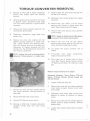
TORQUE CONVERTER REMOVAL
Remove Chain Case Cover
Equipment Necessary: Screwdriver Having a
5/16-lnch Blade, 1/2-lnch Socket, 5/8-lnch
Wrench, 11/16-lnch Wrench, 13/16-lnch Wrench,
and 6-lnch Extension.
2.
Drain fluid from chain case, using a suction
gun.
3.
Remove bolt, lock washer, and flat washer
holding spacer and sprocket on engine PTO
shaft, Fig. 23. Slide spacer off PTO shaft.
Fig. 23
•
CAUTION.
The battery must be removed before working on
any part or component of the drive system. This
will eliminate the possibility of accidental starter
engagement.
1.
Remove the five screws and lock washers
securing chain case cover to chain case.
2.
Remove the two bolts and lock washers
securing chain case cover to chain case.
3.
Disconnect the suction hose from the 90 0
elbow.
4.
Disconnect the return hose from the chain
case cover.
Remove bolt, lock washer, and flat washer
holding chain sprocket on track drive shaft.
5.
Loosen jam nut on chain tensioner bolt, Fig.
24. Loosen chain tensioner bolt.
4.
5.
Pull vent hose fitting out of chain case cover.
6.
Lift cover off chain case.
7.
Remove filter and filter tube.
8.
Remove return line elbow.
9.
Remove suction hose elbow and adapter from
cover.
Fig. 24
6.
Remove Chain and Sprockets
Equipment Necessary: Suction Gun, Screwdriver
Having a 5/16-lnch Blade, 1/2-lnch Socket, and
6-lnch Extension.
•
CAUTION.
The battery must be removed before working
on any part or component of the drive system.
This will eliminate the possibility of accidental
starter engagement.
1.
Slide chain and sprockets off PTO shaft and
track drive shaft.
Remove Engine and Torque Converter
Equipment Necessary: Screwdriver Having a
1/4-lnch Blade, 3-lnch Extension, 6-lnch Extension, 12-lnch Extension, 10mm Wrench, 10mm
Socket, 13mm Wrench, 13mm Socket, 1/2-lnch
Socket, 9/16-lnch Wrench, and 9/16-lnch Socket.
1.
Remove chain case cover, chain, and sprockets (See: Remove Chain and Sprockets, page
31).
Remove chain case cover (See: Remove Chain
Case Cover, page 31).
31
I
I
I
I
I
I
TORQUE CONVERTER REMOVAL
2.
Working on PTO side of engine, disconnect
positive (red) battery cable from solenoid
terminal.
3.
Remove ignition switch connector from back
of ignition switch. Disconnect black single
wire from starter solenoid in ignition switch
connector.
4.
Remove top torque converter case bolt. Remove battery ground cable.
5.
11.
Remove lower fan cover screw securing wire
harness to fan housing.
12.
Disconnect main wiring harness from engine
connector.
13.
Remove bolt, lock washer, and flat washer
securing wire harness to charge pump belt
cover. Move harness away from engine.
14.
Remove three bolts securing recoil assembly
to fan housing.
Disconnect temperature gauge leads from
sender units.
6.
Remove two nuts, lock washers and flat
washers securing carburetor to intake manifold. Loosen throttle wire retaining screw;
then pull throttle wire out of throttle arm.
Disconnect oil injector actuating rod from
throttle arm, Fig. 25. Disconnect impulse line
from fitting on carburetor.
NOTE: Impulse line must be disconnected at
carburetor fitting because it is easily acces-
NOTE: Engine to chassis ground cable (green)
is secured to front recoil mounting bolt.
15.
Remove two lock nuts and flat washers
securing engine motor plate to front and rear
motor mounts on MAG side of engine.
16.
Lift engine and torque converter free of
chassis.
17. Thoroughly clean engine
engine, and torque converter.
compartment,
sible.
18. With engine out of chassis, check ski alignment (See: Panther Service Manual, Section
VII-Steering and Body, Ski Alignment, page
22).
Fig. 25
Remove Torque Converter from Engine
Equipment Necessary: 10mm Socket, 7/16-lnch
Socket, 7/16-lnch Wrench, 3/4-lnch Socket and
3/4-lnch Wrench
7.
Remove two bolts and lock washers holding
rear torque converter mounting bracket to
chain case.
1.
Unlock muffler ball joint clip.
2.
Remove four bolts and lock washers securing
motor plate to engine. Remove motor plate
with muffler.
3.
Disconnect heavy black cable running from
solenoid to starter at terminal on starter
motor.
8.
Remove PTO side front motor mount.
9.
Remove PTa side rear motor mount.
4.
10.
Working on MAG side of en'gine, disconnect
headlight harness plug from main wiring
harness.
Remove two bolts and lock washers securing
support plate to torque converter. Remove
support plate.
5.
Loosen metal pressure tube bracket on engine
shroud.
32
)
TORQUE CONERTER REMOVAL
6.
Remove metal pressure tube.
Disassemble Torque Converter
7.
Disconnect flexible hydraulic hose from converter.
8.
Remove two bolts and lock washers securing
torque converter case halves together.
Equipment Necessary: Rubber Mallet, Large Snap
Ring Pliers, Two Screwdrivers Having a 7/16-lnch
Blade, 9/16-lnch Socket (12-point), 5mm Hex Key
Wrench, 10mm Socket, and 10mm Wrench.
1.
Remove twelve bolts, lock washers, flat washers, and nuts holding converter case and
pumpwheel together, see Fig. 26 . Separate
converter and pumpwheel.
NOTE: Top bolt and lock washer should have
been removed previously when disconnecting
battery ground cable during engine removal.
9.
Slide torque converter off engine mainshaft
splines.
10.
Drain oil remaining in transmission by setting
transmission on output shaft and allowing oil
to drain from inlet fitting.
11.
NOTE: It may be necessary to use a screwdriver to pry converter and pumpwheel apart.
Use extreme care when prying and make certain
contact surfaces are smooth to prevent leaks after
reassembly.
Fig. 26
Remove large seal from rear cover.
Remove Torque Converter Drive Coupler
Equipment Necessary: Press and 13mm Socket
c
aTE: If only drive coupler is to be replaced,
proceed to step 1. If additional work will be
performed on torque converter and drive coupler
removal is unnecessary, disassemble torque converter (See: Disassemble Torque Converter, page
33).
1.
Remove twelve bolts, lock washers, flat washers, and nuts holding converter case and
pumpwheel together, Fig. 25. Separate con '
verter and pumpwheel.
NOTE: It may be necessary to use a screwriver to pry converter and pumpwheel apart.
Use extreme care when prying and make sure
contact surfaces are smooth to prevent leakage
after reassembly.
c
2.
Remove six bolts and lock washers securing
coupler to converter, see Fig. 26.
3.
Press coupler out of converter case, using a
press.
4.
Remove copper gasket.
2.
Remove special lock nut with flange from the
turbine shaft, Fig. 27. Carefully pry bearingl
free of turbine shaft, using two screwdrivers.
Fig. 27
3.
Lift turbine wheel off turbine shaft.
33
TORQUE CONVERTER REMOVAL
4.
Using a large snap ring pliers, remove small
snap ring; then remove large snap ring, Fig.
28. Lift spacer off shaft.
7.
Remove four socket head cap screws and lock
washers securing rear cover and seal to case
assembly, Fig. 30. Remove rear cover and
seal, and gasket.
Fig. 28
Fig. 30
5.
Lift stator off turbine shaft, Fig. 29. Remove
spacer washer.
8.
NOTE: When removing stator, check by
rotating stator counterclockwise. Stator must
lock when turned counterclockwise but must turn
freely when turning clockwise. If stator does not
lock, it must be replaced.
Tap end of turbine shaft, using a rubber
mallet, until turbine shaft is free of converter
case. Remove gasket.
9.
If necessary, press bearing and spacer off
turbine shaft.
10.
Remove pump wheel by prying out of case
assembly.
Fig. 29
11 . Tap rigid shaft out of case, using a rubber
mallet.
Note position of oil holes when
isassembling. Large hole should be at 1
o'clock position and small hole should be at 11
o'clock position.
12.
o
6.
34
Remove snap ring from rigid shaft, using a
large snap ring pliers.
If necessary, remove oil seal in converter case
assembly.
CLEANING &. INSPECTING
Clean and Inspect
3.
Check for cracks, holes, or imperfections in
any of the torque converter castings.
4.
Check for stripped or damaged threads in
castings.
NOTE: Whenever a part is worn excessively,
cracked, defective, or damaged in any way,
replacement is necessary.
5.
Check all machined mating surfaces for imperfections or damage.
1.
Thoroughly wash all grease, fluid, or foreign
matter off all parts, using cleaning solvent.
Dry parts, using compressed air.
6.
2.
Inspect all gaskets, O-rings, and seals for wear
or damage.
Check stator operation. Place stator on turbine shaft. Rotate stator counterclockwise.
Stator should lock after a few degrees of
counterclockwise rotation. Clockwise rotation
should allow stator to turn freely.
Equipment
pressed Air
Necessary:
Cleaning Solvent, Com-
"
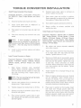
TORQUE CONVERTER INSTALLATION
5.
Working with the turbine shaft, press turbine
shaft bearing until it bottoms against case
casting on shaft. Place an a-ring in the corner
of the bearing inner race. Press bushing onto
turbine shaft (beveled edge toward PTa end).
6.
Insert an oil seal into rear bearing cover. Open
side of seal must face engine MAG side. Place
a small amount of low temperature grease
(Texaco 2346 EP or equivalent) between the
two lips of the seal.
7.
Apply liquid sealer to both sides of flange
gasket for the rear case. Place gasket on rear
case flange.
Install rear cover and seal over turbine shaft
and against gasket on rigid shaft. Rotate cover
until all holes are aligned. Secure cover to rear
case with four socket head cap screws and
lock washers. Tighten socket head screws to
4-5 ft-Ib.
NOTE: Gasket can be installed only one way.
Holes in gasket will not align if incorrectly
installed.
NOTE: If pump wheel was disassembled
completely, proceed to step 8. If wheel was
not disassembled, proceed to step 9.
3.
8.
Press pump wheel bearing into pump wheel
case. Apply liquid sealer to both sides of
pump wheel boss gasket.. Place gasket on
machined surface. Place pump wheel boss in
position on wheel. Secure in place with f'ight
bolts and special washers. Tighten bolts to 3-4
ft-Ib.
9.
Slide assembled pump wheel onto rigid shaft.
Secure in place with a snap ring, using a large
snap ring pliers.
Assemble Torque Converter
-
Equipment Necessary: Low Temperature Grease
(Texaco 2346 EP or equivalent), Liquid Sealer
(Arctic Part No. 3000-211), Torque Wrench, Large
Snap Ring Pliers, 5mm Hex Key Socket, 10mm
Socket, 10mm Wrench, and 9/16-lnch Socket
(12-point)
1.
2.
Place a small amount of low temperature
grease (Texaco 2346 EP or equivalent) between the two lips of the rear case oil seal.
Insert seal into rear case. Open side of seal
must face PTO shaft.
I nsert rigid shaft into rear case.
NOTE: Position of oil holes must be noted.
The small oil hole must be in the eleven
o clock position; the large hole must be in the one
o'clock position.
4.
-(
Apply liquid sealer to both sides of rear cover
gasket. Place gasket on rigid flange surface.
NOTE: Gasket can be installed only one way.
Holes in gasket will not align if incorrectly
installed.
35
TORQUE CONVERTER INSTALLATION
10. Place spacer washer against snap ring; then
Fig. 32
install stator assembly with short blade side
facing outward. Place remaining spacer washer
onto shaft and secure parts in position with a
snap ring, using a snap ring pliers.
)
NOTE: Spacer washers are identical. Either
r may be used in either location.
11.
Check stator for rotation characteristics.
Stator must rotate freely ina clockwise
rotation but lock when rotated counterclockwise.
12.
Install small snap ring on turbine shaft, using
a snap ring pliers. Fig. 31 shows assembly to
this point.
15.
Ensure that machined surfaces of converter
case and pump wheel are free of burrs and
foreign particles. Again check large a -ring to
ensure proper seating.
16.
AI ign marks on outer edges of converter case
and pump wheel, Fig. 33; then secure case
and wheel together with twelve bolts, flat
washers, lock washers, and nuts. Tighten nuts
to 5-7 ft-Ib.
Fig. 31
Fig. 33
13.
Make sure large a-ring is properly seated in
pump wheel.
14. Place turbine wheel on turbine shaft. Slide
bearing onto end of turbine shaft. Secure
parts in place with special lock nut, Fig. 32;
tighten lock nut to 18-20 ft-I b. The beari ng
will be drawn evenly onto shaft as sprocket
lock nut is tightened. Turbine wheel should
have no freeplay on turbine shaft.
NOTE: If drive coupling was removed, assemble (See:
Install Torque Converter Drive
pier, page 37); then proceed with step 15.
17. Place a small amount of low temperature
grease (Texaco 2346 EP or equivalent), between two lips of large outside rear cover seal.
Slide seal over rear cover. Open side of seal
must be toward converter PTa shaft.
-
TORQUE CONVERTER INSTALLATION
Install Torque Converter Drive Coupler
6.
Connect heavy black cable to terminal on
starter. Tighten nut securely.
Equipment Necessary: Liquid Sealer (Arctic Part
No. 3000-211), Press, Torque Wrench, and 13mm
Socket
7.
Place motor plate and muffler in position.
Secure assembly to engine with four bolts and
lock washers. Tighten bolts to 45 ft-/b.
1.
Ensure all surfaces are smooth and clean.
8.
Now tighten support plate bolts to 45 ft-Ib.
2.
Apply liquid sealer (part no. 3000-211) to
both surfaces of copper gasket.
9.
Secure muffler to exhaust manifold with
muffler joint clip.
Place gasket on converter case and align bolt
holes.
Install Engine and Torque Converter
3.
4.
Press drive coupling into converter case until
seated.
If drive coupling is replaced, the
upling must be replaced for the specific torque converter model (See: Section IX-Parts Manual,
page IX-21). Also new plug must be installed in
coupling.
5.
I nstall six bolts and lock washers and tighten
to 14 - 16 ft-Ib.
Equipment Necessary: Silicone Seal or Bathtub
Seal, Torque Wrench, 1/2-lnch Socket, 1/2-lnch
Wrench, 9/16-lnch Socket, 9/16-lnch Wrench,
5/B-lnch Wrench, 1-lnch Wrench, 10mm Socket,
10mm Wrench, 13mm Wrench, and a Screwdriver
Having a 1 14-lnch Blade.
1.
Set engine and torque converter assembly
onto motor mounts.
2.
Fasten rear torque converter mounting bracket to chain case with two bolts and lock
washers. Tighten bolts to 17 ft-Ib.
3.
Working on MAG side of snowmobile, secure
engine motor plate to motor mounts with two
lock nuts and flat washers. Tighten lock nuts
to 35 ft-Ib. Install carburetor on intake
manifold. Secure carburetor in place with two
nuts, lock washers, and flat washers. Tighten
nuts to 16 ft-Ib.
4.
Install impulse line to impluse fitting on top
of carburetor.
5.
Slide oil injector actuating wire over throttle
arm on carburetor. Insert throttle wire in
throttle arm bracket. Pull out all slack from
throttle wire, plus an additional 1/ 16-inch to
preload throttle safety switch. Secure throttle
wire with thr.ottle arm retaining screw.
6.
Place recoil in position on fan housing. Install
one recoil bolt through ground cable and
secure front of recoil to fan housing. Install
top recoil bolt so that injector tank mounting
bracket is secured. Install lower recoil mounting bolt. Tighten all recoil bolts to 5 ft -Ib.
Install Torque Converter on Engine
Equipment Necessary: Torque Wrench, 7/16-lnch
Socket, 7/16-lnch Wrench, 5/B-lnch Wrench,
3/4-lnch Socket, 3/4-lnch Wrench and 13mm
Socket.
1.
SI ide torq ue converter onto crankshaft
splines. Secure converter assembly in place
with two bolts and lock washers in front and
rear case mounting holes. Tighten bolts to
12-14 ft -Ib.
TE: The top mounting bolt will be instaled during engine installation.
2.
Connect steel pressure line to converter and
charge pump. Tighten securely.
3.
Tighten pressure line bracket bolt to 10 ft-Ib.
4.
Connect one end of converter output line to
converter and tighten.
5.
Place torque converter support plate in position. Secure with two bolts, and lock washers.
DO NOT tighten.
37
TORQUE CONVERTER INSTALLATION
7.
Secure wire harness to top of pump pulley
cover with top rear mounting bolt. Tighten
bolt to 5 ft-Ib. Plug main harness plug into
engine connector. Secure front of harness to
fan cover mounting screw.
21.
Install vent line fitting in vent hole in chain
case cover.
22.
Fill chain case with required amount of
torque converter fluid.
8.
Connect headlight harness to main wiring
harness.
23.
Place battery in battery pan. Secure with
battery hold-down bracket.
9.
Connect temperature gauge sender leads to
temperature gauges.
24.
Connect red battery lead (positive lead) and
red wire running to circuit board to positive
(+) terminal on battery.
25.
Connect black battery lead (negative lead) to
negative (-) terminal on battery.
10. Working on PTa side of snowmobile, connect
black wire from solenoid to connector on
back of ignition switch so it will match "S"
terminal on ignition switch .
NOTE: Locking tab on wire terminal end
must be bent to a 45 0 outward angle to
ensure locking.
11.
Connect heavy red battery cable to remaining
termi nal on starter solenoid.
12. Place spacer washers on torq ue converter PTa
shaft.
13.
Place track drive shaft spacer onto splines of
shaft in chain case.
14.
I nstall chain and sprockets (See: I nstall Chain
and Sprockets, page 39.
15.
Place flat washer and lock nut on rear motor
mount stud. Tighten to 35 ft -Ib.
16.
NOTE: Chain must be very tight. While
tightening chain tension, watch rubber mount
at rear of converter case. When rubber mount starts
to compress, stop tightening and back bolt off
about 1/2 turn.
18. Tighten tensioner bolt jam nut.
19. Connect suction hose to chain case cover.
38
Install Chain and Sprockets
Equipment Necessary: Silicone Seal or Bathtub
Seal, Torque Wrench, Screwdriver Having a
5/16-lnch Blade, 1/2-lnch Wrench, and 6-lnch
Extension
1.
Slide small chain sprocket halfway onto
torque converter PTa shaft.
2.
Loop drive chain over sprocket. Place chain
around large chain sprocket.
3.
Place sprocket on track drive shaft splines.
4.
Slide both sprockets and chain onto shaft
splines.
Place flat washer and lock nut on front motor
mount. Tighten to 35 ft-Ib.
17. Tighten chain tensioner bolt located on underside of chain case.
20.
26. Start engine and check to ensure everything is
adjusted correctly.
Connect converter output hose to chain case
cover.
NOTE: Chain tightener mechanism must be
loose when installing chain and sprockets.
5.
Secure sprocket on track drive shaft with a
large flat washer, lock washer, and bolt.
Tighten bolt to 2 ft-Ib.
6.
Check sprocket alignment (See:
Alignment Adjustment, page 39) .
7.
Install long bushing and spacer washer on
PTa shaft. Secure parts in place with a bolt,
lock washer, and flat washer. Tighten bolt to
20 ft-Ib. Fig. 34 shows small sprocket assembly.
Sprocket
'J
TORQUE CONVERTER INSTALLATION
Install Chain Case Cover
Fig. 34
Equipment Necessary: Silicone Seal or Bathtub
Seal, 1/2-lnch Socket, 11/16-lnch Wrench,
13/16-lnch Wrench, 1-lnch Wrench, and 6-lnch
Extension
1.
Install suction hose elbow and adapter in
chain case cover. Tighten securely.
2.
Install return line elbow.
3.
Install filter and filter tube.
4.
Apply a liberal amount of silicone seal or
bathtub seal on both sides of chain case cover
gasket.
7.
Connect fluid return hose to chain case cover.
5.
Place gasket on chain case surface.
8.
Connect suction hose to chain case cover
fitting.
6.
Place chain case cover on gasket and secure
with five screws and lock washers and two
bolts and lock washers. Tighten screws . Tighten two bolts.
9.
Install and connect battery.
r
CHAIN & SPROCKET ADJUSTMENTS
Chain Tension
Fig. 35
Equipment Necessary: 1 /2-lnch Wrench
1.
Loosen chain tensioner bolt jam nut, Fig. 35.
2.
Tighten chain tension bolt located on underside of chain case, Fig. 35.
NOTE: Chain must be very tight. While
tightening chain tension, watch rubber mount
at rear of converter case. When rubber mount starts
to compress, stop tightening adjuster bolt and back
bolt off about 1/2 turn.
3.
Tighten tension bolt jam nut.
Sprocket Alignment
Equipment Necessary: Torque Wrench, Screwdriver Having a 5/16 1nch Blade, 1/2-1 nch Socket,
16-lnch Straight Edge.
39
CHAIN 8r. SPROCKET ADJUSTMENTS
1.
Remove five screws and lock washers and two
bolts and lock washers securing chain case
cover in position.
2.
Lift chain case cover off chain case.
3.
Check sprocket alignment by laying a 16-inch
straight edge against faces of engine and drive
shaft sprockets. No visible gap is to be evident
between straight edge surface and sprocket
face.
4.
If adjustment is necessary, remove bolt and
flat washer from engine PTa shaft.
NOTE: All adjustments must be made with
ine sprocket.
5.
Remove long spacer.
NOTE: If sprocket was inside of parallel,
install a shim between torque converter and
sprocket. If sprocket was outside of parallel, a shim
must be removed from between torque converter
and sprocket.
6.
When correct sprocket alignment is established, place long spacer on engine PTa shaft;
then secure in place with flat washer, lock
washer, and bolt. Tighten bolt to 20 ft-Ib.
CHARGE PUMP
Remove Charge Pump
Fig. 37
Equipment Necessary: Screwdriver Having a
1/4-lnch Blade, Screwdriver Having a 5/16-lnch
Blade, 3-lnch Extension, 6-lnch Extension, 10mm
Socket, 1/4-lnch Bolt, 7/16-lnch Socket, 7/16-lnch
Wrench, 3/4-lnch Wrench, and 1-lnch Wrench.
TE: Charge pump may be removed either
engine in chassis or with engine removed.
1.
Remove recoil from engine by removing three
recoil bolts, Fig. 36.
Fig. 36
2.
Loosen steel hydraulic line clamp and remove
steel hydraulic line.
3.
Remove large suction line from charge pump.
4.
Remove oil injector inlet line from injector,
Fig. 37. Plug line with a 1/4-inch bolt.
40
5.
Loosen throttle wire retaining screw on throttle arm, Fig. 38. Pull throttle wire out of arm;
then slide injector actuating lever off throttle
arm.
6.
Remove two screws securing oil injector to
chargepump. Slide injector pump free of
charge pump.
7.
Remove two bolts securing charge pump to
pump holder. Slide charge pump out of pump
holder.
NOTE: Charge pump is available only as an
assembled unit. If pump is defective it must
replaced as a unit.
r-'\
J
CHARGE PUMP
Fig. 38
c
2.
Place injector in position against charge
pump. Install two mounting screws and
tighten to 5 ft-Ib.
3.
Remove plug from oil inlet line and secure
line to injector oil inlet fitting with oil line
clamp.
4.
Install steel hydraulic line. Connect fittings to
both torque converter and charge pump.
Tighten clamp bolt to 10ft-lb.
5.
I nstall large hydraulic suction tube to charge
pump and secure in place.
6.
Slide end of injector actuating arm over
throttle arm. Insert throttle wire into throttle
arm bracket. Pull out all slack from throttle
wire plus an additional 1/16 inch to preload
throttle safety switch. Tighten throttle retaining screw.
Install Charge Pump
7.
Install recoil. Secure in place with three bolts.
Tighten to 5 ft-Ib.
Equipment Necessary: Torque Wrench, Screwdriver Having a 1/4-lnch Blade, Screwdriver Having
a 5/16-lnch Blade, 10mm Socket, 7/16-lnch Socket, 7/16-lnch Wrench, 3/4-lnch Wrench, and 1-lnch
Wrench.
NOTE: Green engine-to-chassis ground cable
must be secured to one of the recoil mounting
bolts.
1.
Place charge pump in position against pump
holder. Secure pump in place with two bolts.
Tighten bolts to 5 ft-Ib.
TRACK DRIVE
Remove Track Drive Shaft
Equipment Necessary: Hammer, Hoist, Suction
Gun, 1/8-lnch Hex Key Wrench, 5/16 x 1/8-lnch
Flat End Punch, 7/16-lnch Socket, 7/16-lnch
Wrench, 1/2-lnch Socket, 1/2-lnch Wrench, and
6-lnch Extension.
I
I.
r
1.
Remove chain case cover and sprockets (See:
Remove Chain and Sprockets, page 31).
2.
Remove skid frame from tunnel (See: Panther
Service Manual, Section VI - Suspension, Skid
Frame Removal, page VI-3).
3.
Drain lubricant from chain case, using a
suction gun.
4.
Remove two bolts and lock nuts securing
speedometer drive unit to brake assembly,
Fig. 39.
Fig. 39
41
TRACK DRIVE
5.
Remove
bracket.
mounting
13.
Loosen set screw securing bearing lock collar
on MAG end of track drive shaft.
6.
Lift brake assembly up until it is free of
mounting studs. Slide brake disc and brake
assembly off drive shaft splines.
14.
Drive lock collar in opposite direction of shaft
rotation to loosen, using a 5/16 x 1/8-inch
flat end punch and hammer.
15.
Remove flanges, bearing, and lock collar from
the track drive shaft. Track drive shaft is
completely disassembled at this time.
TE:
7.
brake
assembly
from
Brake tension spring can be left
Raise back end of snowmobile off shop floor,
using a hoist.
8.
On PTa side of snowmobile, remove three
lock nuts, flat washers, and a-rings securing
bearing flanges to tunnel. Remove bolts,
flange, spacer, a-ring, bearing, flange, and
gasket in their respective order.
9.
On MAG side of snowmobile, remove three
bolts and lock nuts securing MAG side drive
shaft bearing and flanges and brake mounting
bracket to tunnel.
10.
Remove two lock nuts, four sprocket washers,
and two bolts securing PTa side track drive
sprocket to track drive shaft, Fig. 40.
NOTE:
The PTa side track drive shaft
can be removed but is not available
as a replacement part. If a track drive sprocket
needs replacement, the entire drive shaft assembly
must be replaced as a unit.
Install Track Drive Shaft
Equipment Necessary: Hammer, Hoist, Silicone
Seal or Bathtub Seal, Steel Tape Measure, Torque
Wrench, 1I8-lnch Hex Key Wrench, 5/16 x
1I8-lnch Flat End Punch, 7/16-lnch Socket,
7/16-1 nch Wrench, 1/2-lnch Socket, and
1/2-lnch Wrench.
1.
Set track drive shaft on bench. Slide lock
collar (Large 10 toward end of shaft), bearing
retainer (flange toward lock collar), bearing
(race toward sprocket), and bearing retainer
(flange toward end of shaft) on MAG side of
track drive shaft.
2.
Raise rear of snowmobile off shop floor, using
a hoist.
3.
Place track drive shaft between track. Slide
PTa side sprocket toward center of shaft.
4.
Lift track drive shaft and track into position
between front end assembly; then push short
splined end of track drive shaft through hole
in chain case and front end. Continue pushing
until opposite end of track drive shaft can be
pushed through hole in front end on MAG
side of snowmobile.
5.
Apply a liberal amount of bathtub sealer to
both sides of PTa side flange gasket and
around both holes. Place gasket in position.
6.
Install bearing retainer (flange toward nylon
sprocket), bearing (race toward end of shaft),
a -ring, and bearing retainer (flange toward
end of shaft) on PTa end of track drive shaft.
Fig. 40
11. Slide track drive sprocket toward center of
drive shaft.
12. Push track drive shaft toward PTa side until
MAG end of track drive shaft can be swiveled
downward and free of chassis; then slide PTa
end of shaft free of chassis.
NOTE: If complete disassembly of drive shaft
is necessary, proceed to step 13.
42
("
\
-
\.._)
TRACK DRIVE
7.
Install three carnage bolts through bearing
retainers, gasket, and th rough front end. Place
an a-ring, flat washer, and lock nut on each
carriage bolt. DO NOT TIGHTEN nuts at this
time.
Head of carriage bolt is to be posioned on inside of chain case.
rotation, using a 5/16 x 1/8-inch flat end
punch and hammer.
and bearing are locked
en bearing begins to turn with lock collar.
14. Tighten lock collar set screw.
15.
8.
On PTa side of track drive shaft, slide bearing
and retainer plates against inside of tunnel.
Align holes in bearing retainer plates and
tunnel; then insert three carriage bolts.
NOTE: Head of carriage bolt is to be toward
inside of tunnel.
9.
Place brake mounting bracket against tunnel
and over carriage bolts so ends of carriage bolts are exposed; then secure with three
lock nuts.
10.
Now tighten six lock nuts securing drive shaft
bearing flanges.
16. Slide brake disc onto MAG end of track drive
shaft. Ensure that disc slides freely on shaft.
17. Connect brake return spring to chassis and to
brake arm; then place brake assembly onto
brake mounting bracket studs. Secure in
position with two lock nuts. Tighten lock
nuts to 17 ft-Ib.
18.
(,
11. SI ide PTa side track drive sprocket into
position. Secure sprocket in place with two
bolts, lock nuts, and four sprocket washers.
Tighten lock nuts to 17 ft-Ib.
12. AI ign track drive shaft sprockets so that
sprocket edges are equidistant from inside
edge of tunnel, using a steel tape measure.
13. When correct alignment is established, slide
MAG side bearing lock collar against bearing.
Drive lock collar in direction of normal shaft
I nstall skid frame (See: Panther Service Manual, Section VI - Suspension, Skid Frame
Installation, page VI-14).
Align square speedometer drive pin with hole
in track drive shaft. Slide speedometer drive
unit into position. Secure to brake unit with
two bolts and lock nuts. Tighten lock nuts to
8 ft-Ib.
19. Place sprocket spacer on PTa side of track
drive shaft.
20.
I nstall chain case cover and sprockets (See:
Install Chain and Sprockets, page 38).
21.
Add required amount of lubricant to chain
case.
22.
Install and connect battery.
TRACK
General
It
(
The track is composed of three belts, held together
by three-quarter length cleats, which are riveted to
the track belts. Both outer belts have molded
internal drive lugs on their inside surfaces. These
drive lugs engage the track drive shaft sprockets to
provide efficient, smooth power transfer. The track
not only drives the snowmobile, but also acts as a
cushion to absorb minor impacts, and, working in
conjunction with the brake, exerts a drag on the
snow surface to aid in slowing down or stopping.
NOTE: When the molded internal drive lugs
become worn on one side because of excessive
usage, the track can be reversed to get maximum
track life.
Remove Track
Equipment Necessary: Hammer, Hoist, Suction
Gun, 1I8-lnch Hex Key Wrench, 5/16 x 1I8-lnch
Flat End Punch, 7/16-lnch Socket, 7/16-lnch
Wrench, 1/2-lnch Socket, 1/2-lnch Wrench, and
6-lnch Extension
1.
Remove chain and sprockets (See: Remove
Chain and Sprockets, page 31).
43
TRACK
2.
Remove skid frame and track drive shaft (See:
Remove Track Drive Shaft, page 41) .
NOTE: At this time, the track drive shaft and
ck are removed from between the tunnel.
Install Track
Equipment Necessary: Hammer, Hoist, Torque
Wrench, 1/8-lnch Hex Key Wrench, 5/16 x
1/8-lnch Flat End Punch, 7/16-lnch Socket,
7/16-lnch Wrench, 1/2-lnch Socket, 1/2-lnch (
Wrench, and 6-lnch Extension.
1.
I nstall track drive shaft and skid frame (See:
Install Track Drive Shaft, page 42).
2.
Install chain and sprockets (See: Install Chain
and Sprockets, page 38).
(
44
"
NOTES
o
c
I
l