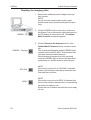
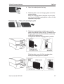
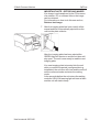
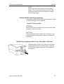
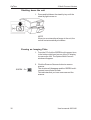
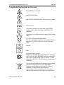
1
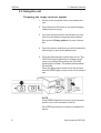
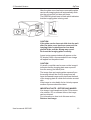
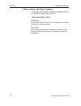
User’s Manual
for the
OpTime Standard version
and the
OpTime Multiconnect version
Number 8201146 rev. 414 (0711)
USA
OpTime
User’s Manual
for the
OpTime Standard version
and the
OpTime Multiconnect version
This unit is marked according to the Medical Device Directive
93/42/EEC (if the unit contains the CE mark)
User’s Manual for the OpTime
Number 8201146 rev. 414 (0711)
Original approved English language version
Manufactured by SOREDEX
Nahkelantie 160,Tuusula
P.O. BOX 148
FI-04301 Tuusula
Finland
Tel. +358 45 7882 2000
Fax. + 358 9 701 5261
User’s manual 8201146
I
OpTime
Soredex endeavours to produce product documentation that is accurate and up
to date. However, our policy of continual product development may result in
changes to products that are not reflected in the product documentation. Therefore, this document should not be regarded as an infallible guide to current
product specifications. Soredex maintains the right to make changes and
alterations without prior notice.
II
User’s manual 8201146
OpTime
Contents
1. Introduction ...................................................................................... 1
1.1 The OpTime ................................................................................................ 1
1.2 Warnings and precautions ........................................................................... 2
1.3 Positioning the unit ...................................................................................... 3
1.4 Handling Imaging Plates .............................................................................. 3
1.5 Cleaning Imaging Plates .............................................................................. 4
1.6 IDot identification code ................................................................................ 4
2. OpTime - Standard version .............................................................. 5
2.1 Main parts and controls ............................................................................... 5
2.2 Indicator lights ............................................................................................. 6
2.3 Using the unit ............................................................................................... 8
Preparing the image read-out system ........................................................... 8
Preparing the imaging plate ......................................................................... 9
Taking an exposure using the imaging plate ............................................... 10
Reading the imaging plate ..........................................................................11
Retrieve last image .................................................................................... 15
Image quality warning message ............................................................. 16
Removing imaging plates from the plate collector ....................................... 17
Shutting down the unit ................................................................................. 17
Erasing an Imaging Plate ........................................................................... 18
3. OpTime - Multi-Connect version .................................................... 20
3.1 Main parts and controls ............................................................................. 20
3.2 Indicator lights ........................................................................................... 21
3.3 Using the unit ............................................................................................. 23
Preparing the image read-out system .........................................................
Preparing the imaging plate .......................................................................
Taking an exposure using the imaging plate ...............................................
Reading the imaging plate .........................................................................
Retrieve last image ....................................................................................
Image quality warning message .............................................................
User’s manual 8201146
23
24
25
26
30
31
III
OpTime
Removing imaging plates from the plate collector ....................................... 31
Shutting down the unit ................................................................................. 32
Erasing an Imaging Plate ........................................................................... 32
4. Setup options ................................................................................. 35
4.1 Show Image Preview and Dental Chart ...................................................... 35
4.2 Resolution ................................................................................................. 35
4.3 Noise filtering ............................................................................................ 36
5. Cleaning and disinfecting the unit .................................................. 37
5.1 Cleaning the unit ........................................................................................ 37
5.2 Disinfecting unit ......................................................................................... 37
6. Maintenance, repair and disposal .................................................. 38
6.1 Maintenance.............................................................................................. 38
6.2 Repair ....................................................................................................... 38
6.3 Disposal .................................................................................................... 38
7. Symbols that appear on the unit .................................................... 39
8. Technical Specifications ................................................................ 40
8.1 OpTime Unit .............................................................................................. 40
8.2 Imaging Plates .......................................................................................... 41
8.3 Main dimensions ....................................................................................... 42
IV
User’s manual 8201146
Introduction
OpTime
1. Introduction
1.1 The OpTime
This manual describes how to operate the OpTime
intraoral imaging plate unit.
The unit is designed to read 0, 1, 2, and 3 size
intraoral imaging plates supplied by Soredex.
The unit works in conjunction with a PC in which
compatible dental imaging software, such as Digora
for Windows 2.5 or above, has been installed.
The OpTime can be configured to work with a single
PC, the Standard version or in a shared environment
where the unit is accessed from different PCs, the
Multi-Connect version.
Only the manufacturer’s authorized personnel are
allowed to install and configure the OpTime intraoral
imaging plate unit.
User’s manual 8201146
1
OpTime
Introduction
1.2 Warnings and precautions
CAUTION - CLASS 3B LASER RADIATION WHEN OPEN
AVOID EXPOSURE TO BEAM
CAUTION - Use of controls or adjustments or performance of procedures other than those specified
herein may result in hazardous laser radiation exposure
•
When handling imaging plates, plate covers and protective bags always take the appropriate
hygiene measures and precautions to prevent cross contamination.
•
The imaging plates are harmful if swallowed.
•
Do not move or knock the unit when it is reading an imaging plate.
•
The use of control or adjustment or performance of procedures other than those specified herein
may result in hazardous laser radiation exposure.
•
This unit must only be used to read SOREDEX OPTIME image plates and must not be used for
any other purpose. NEVER use imaging plates or protective covers from other manufacturers.
•
This unit, or its accessories, must not be modified, altered or remanufactured in any way.
•
Only the manufacturer’s authorized service personnel are authorized to carry out maintenance
and repair. There are no user serviceable parts inside the unit.
•
Infection control procedures must be observed when using accessories, such as film holders, xray tube guides and imaging plates. When using accessories always follow the manufacturer’s
instructions on how to use the accessory and prevent cross contamination from one patient to
another.
•
This device can interfere with other devices due to its EMC characteristics.
•
Other devices can interfere with this device due to their EMC characteristics.
•
This device complies with IEC 60601-1 standard. Accessory equipment connected to this device
must be in compliance with the related nationally harmonized IEC standards.
•
Equipment not suitable for use in the presence of flammable anaesthetic mixture with air or with
oxygen or nitrous oxide.
•
•
2
Only use the SKYNET SNP-PA59-M power supply unit that is supplied with the
unit. Do not use any other power supply units with the unit.
If this device will be used with 3rd party imaging application software not supplied by SOREDEX,
the 3rd party imaging application software must comply with all local laws on patient information
software. This includes, for example, the Medical Device Directive 93/42/EEC and/or FDA if
applicable.
User’s manual 8201146
Introduction
OpTime
1.3 Positioning the unit
Do NOT position the unit so that the door is in or near
very bright light.
Do NOT position the unit on a surface that can vibrate.
1.4 Handling Imaging Plates
Handle imaging plates with care. Hold them by their
edges and avoid touching the active (pale blue) surface. Also avoid situations that could scratch the
active surface. For example NEVER leave imaging
plates active side down on a surface.
Imaging Plates MUST always be used with plate
covers and protective bags as described in this
manual.
After exposing an imaging plate and removing the
imaging plate and plate cover from the protective
bag, do NOT expose the imaging plate and plate
cover to very bright light before reading the imaging
plate.
Read the imaging plate as quickly as possible after it
has been exposed.
Do not leave read or unread imaging plates in their
protective bags for long periods of time.
When imaging plates are not being used, store them
in their protective box below 33°C.
User’s manual 8201146
3
OpTime
Introduction
1.5 Cleaning Imaging Plates
If the Imaging Plates are handled with care they will
not need to be cleaned, see 1.4 Handling Imaging
Plates, above.
If the Imaging Plates are dusty the dust can be carefully wiped off using lint-free cotton or a lens cleaner. If
there are finger prints or other marks on the active
(pale blue) surface they can be removed by very
gently wiping the surface with a lint-free cloth dampened with ethanol anhydride. DO NOT rub the active
surface and DO NOT use any other cleaning agents
NEVER use abrasive cleaners to clean Imaging
Plates.
1.6 IDot identification code
The IDot allows you to identify individual imaging
plates. It also serves as an orientation marker.
4
User’s manual 8201146
2. Standard Version
OpTime
2. OpTime - Standard version
2.1 Main parts and controls
User’s manual 8201146
5
OpTime
2. Standard Version
2.2 Indicator lights
The different statuses of the indicator lights are described below.
Stand-by light on
Unit is shut down (OFF).
Press stand-by key to switch unit on.
GREEN on
Unit ready to read an imaging plate.
Insert imaging plate.
GREEN slow flashing
Unit in the energy save mode.
Press the Start key to enter ready mode.
GREEN fast flashing
Unit is reading/erasing an imaging plate.
YELLOW on
DfW not opened or untransferred image in unit.
Open DfW and the image will automatically appear.
YELLOW slow flashing
There is no Ethernet link.
YELLOW fast flashing
Unit carrying out its selftest.
6
User’s manual 8201146
2. Standard Version
OpTime
GREEN on, YELLOW on
Unit is in the Erase mode.
GREEN flashing, YELLOW on
Unit is in the Erase mode and is erasing an imaging
plate
GREEN on, YELLOW flashing
Unit is entering the energy save mode
RED flashing
ERROR. Switch the unit off and then on again. If the
red light comes on again, contact your dealer for help.
User’s manual 8201146
7
OpTime
2. Standard Version
2.3 Using the unit
Preparing the image read-out system
1. Switch on the computer that is connected to the
unit.
2. Open Digora for Windows or the dental imaging
software you are using.
3. If you are using the unit for the first time you may
wish to check and/or change the setup options.
See section 4 Setup options for more information.
4. Open the patient card where you wish to place the
new image, or open a new patient card.
5. Press the Stand-by key to switch the unit on. The
YELLOW stand-by light will turn off and unit will
carry out a selftest during which the YELLOW
warning light will flash. The selftest will last about
30 seconds.
When the plate carrier slides out of the unit door
and the GREEN light comes on the unit is ready to
use.
NOTE
If the GREEN light does not come on it indicates
that the unit is not connected to the PC.
If the RED light comes on contact your dealer for
advice.
8
User’s manual 8201146
2. Standard Version
OpTime
Preparing the imaging plate
IMPORTANT NOTE
If the imaging plate is being used for the very first time
or if it has not been used within the last five days, it
MUST be erased. See section 3. Erasing an imaging
plate, for information on how to do this.
CAUTION
When handling imaging plates, plate covers and
protective bags always take the appropriate hygiene
measures and precautions to prevent cross contamination.
1. Hold imaging plates by their edges and avoid
touching the surfaces of the plates.
Place the imaging plate you plan to use onto the
long half of the plate cover. The blue (active) side
of the imaging plate must face the plate cover and
the metal disk, on the back of the imaging plate,
must be positioned near the outer edge of the
plate cover.
2. Fold the short half of the plate cover over onto the
imaging plate.
3. Slide the plate cover and imaging plate into the
protective bag as far as it will go.
User’s manual 8201146
9
OpTime
2. Standard Version
The black side of the plate cover, must be against
the black side of the protective bag.
4. Remove the cover paper from the sealing tape.
Fold the flap over onto the sealing tape and
smooth the flap from the centre out to ensure that
the seal does not wrinkle.
Taking an exposure using the imaging plate
1. Place the sealed protective bag in the patient’s
mouth in the required position for the image you
wish to take. The back of the protective bag, the
black side, must face away from the X-ray source.
2. Select an exposure value appropriate for the
exposure you are taking. The unit can read images taken with exposure times from 0.05 to 0.63
seconds at 7 mA.
3. Protect yourself from radiation and take the exposure.
10
User’s manual 8201146
7uj7uj7
2. Standard Version
OpTime
Reading the imaging plate
1. Remove the sealed protective bag from the patient’s mouth.
uj7uj
NOTE
If a risk of cross contamination exists, wash,
disinfect and dry the protective bag before opening it.
2. Open the sealed protective bag.
3. Slide the plate cover and imaging plate out of the
protective bag.
Keep the imaging plate in the plate cover so that
you do not touch the imaging plate or allow it to be
exposed to bright light.
4. If unit door is closed and the GREEN light is
flashing, the unit is in the energy save mode,
Press the Start key. The unit door will open, the
plate carrier will slide out and the GREEN light will
stop flashing and remain on.
User’s manual 8201146
11
OpTime
2. Standard Version
CAUTION
If the GREEN and YELLOW lights are both
on, it indicates that the unit is in the Erase
mode. DO NOT attempt to read an imaging
plate when the unit is in the erase mode. To
exit the Erase mode press and hold down the
Start key until the YELLOW light goes out.
5. Slide the imaging plate and plate cover into the
plate carrier as far as they will go. The back of the
imaging plate (the black side with the metal disk)
must face the plate carrier.
A magnet will hold the imaging plate in position.
Slide the plate cover off of the imaging plate,
leaving the imaging plate in position.
12
User’s manual 8201146
2. Standard Version
OpTime
After the plate cover has been removed the plate
carrier with imaging plate will automatically slide
into the unit and the unit door will close.
The GREEN light will start to flash which indicates
that the imaging plate is being read.
CAUTION
If the plate carrier does not slide into the unit
after the plate cover has been removed, the
imaging plate is misaligned or has been
placed in the unit the wrong way round.
Re-insert the imaging plate correctly.
A read-out progress window will appear on the
PC display. After a few seconds the new image
will appear on the patient card.
CAUTION
If a small round disk can be seen on the image it
indicates that the imaging plate was exposed
from the wrong (the black) side.
The image from an imaging plate exposed from
the wrong side will be a mirror image and will
have decreased image quality because the back
of the imaging plate is metal and includes a metal
disk.
If the image is not suitable for its clinical purpose
another exposure should be taken.
IMPORTANT NOTE - RETRIEVING IMAGES
If an image is not transferred to the PC because
of a network, PC or software failure, the image
can be retrieved.
For information on how to do this see section,
Retrieve last image.
User’s manual 8201146
13
OpTime
2. Standard Version
6. After the imaging plate has been read it will be
erased and then automatically ejected from the
unit into the plate collector.
After the imaging plate has been ejected the
GREEN light will remain on and the unit door will
stay open. The unit is now ready to read the next
imaging plate
If no new imaging plate is inserted into the unit
within a certain time period the unit door will close
and the unit will enter the energy save mode.
Five seconds before the unit enters the energy
save mode the YELLOW warning light will start to
flash and the unit will start to beep.
After five seconds the plate carrier will slide back
inside the unit, the door will close, the YELLOW
light will go out and the GREEN light will start to
flash. The unit is now in the energy save mode.
If the Start button is pressed while the YELLOW
warning light is flashing, the unit will not enter the
energy save mode.
14
User’s manual 8201146
2. Standard Version
OpTime
To exit the energy save mode press the Start
button. The plate carrier will slide out and the
GREEN light will stop flashing and stay on. The
unit is now in the ready mode.
Retrieve last image
If the last image read is not transferred to the PC
because of a network, PC or software failure, the
image can be retrieved.
IMPORTANT NOTE
The LAST read image can only be retrieved if the unit
has been left connected to the power supply. If the unit
has been disconnected the image will be lost.
To retrieve the last image:
1. Correct the problem that caused the network
failure, and then reopen the new or existing patient card.
2. The last scanned image should automatically be
transferred.
If it is not, from the dental imaging software your
are using select Digora Optime Setup > Scanner page.
3. In the Retrieve Last Image field, click the check
box to retrieve the last read image.
4. Click OK to close the Digora Optime Setup
window will close.
The last read image will appear on the patient
card.
User’s manual 8201146
15
OpTime
2. Standard Version
Image quality warning message
The following WARNING message may appear on the
PC display during or after read-out:
- Degraded image quality
PROBLEM
Some of the read out lines on the image are not within
the factory set quality limits.
SOLUTION
If the image looks okay no action is necessary. If the
message appears frequently, contact your dealer for
assistance.
16
User’s manual 8201146
2. Standard Version
OpTime
Removing imaging plates from the plate collector
1. Slide the plate collector out of the unit and tip the
imaging plates out onto a flat surface. If they are
not to be used again, store them in the optional
storage box.
Shutting down the unit
1. Press and hold down the stand-by key until the
stand-by light comes on.
NOTE
If the unit remains in the energy save mode for
several hours (door closed and green light flashing), it will automatically shut down.
NOTE
If there is an untransferred image in the unit, the
unit will not automatically shut down.
User’s manual 8201146
17
OpTime
2. Standard Version
Erasing an Imaging Plate
1. Press the Stand-by key to switch the unit on. After
60 seconds the plate carrier will slide out of the
unit.
2. Press and hold down the Start key, the GREEN
light will flash, until the YELLOW light comes on.
When both lights are on the unit is in the Erase
mode.
3. Slide the imaging plate into the plate carrier as far
as it will go. The back of the imaging plate (the
black side with the metal disk) must face the plate
carrier.
A magnet will hold the imaging plate in position.
18
User’s manual 8201146
2. Standard Version
OpTime
Release the imaging plate and the plate carrier
will slide into the unit and the unit door will close.
The YELLOW light will stay on and the GREEN
light will start to flash which indicates that the
imaging plate is being erased.
4. After the imaging plate has been erased it will be
automatically ejected from the unit into the plate
collector.
The imaging plate can now be used to take an
exposure
5. To exit the Erasing mode, either wait 15 seconds
for the unit to automatically exit the mode, or press
and hold down the Start key until the YELLOW
light goes out.
User’s manual 8201146
19
OpTime
3. Multi-Connect Version
3. OpTime - Multi-Connect version
3.1 Main parts and controls
20
User’s manual 8201146
3. Multi-Connect Version
OpTime
3.2 Indicator lights
The different statuses of the indicator lights are described below.
Stand-by light on
Unit is shut down (OFF).
Press stand-by key to switch unit on.
GREEN on
Unit is reserved and ready to read an imaging plate.
Insert imaging plate.
GREEN slow flashing
Unit in the waiting mode.
Click the Multi-connect icon to reserve the unit.
GREEN fast flashing
Unit is reading/erasing an imaging plate.
YELLOW on
Imaging software not opened or untransferred image
in unit.
Open imaging software and retrieve the pending
image if necessary.
YELLOW slow flashing
There is no Ethernet link.
YELLOW fast flashing
Unit carrying out its selftest.
User’s manual 8201146
21
OpTime
3. Multi-Connect Version
GREEN on, YELLOW on
Unit is in the Erase mode.
GREEN flashing, YELLOW on
Unit is in the Erase mode and is erasing an imaging
plate
GREEN on, YELLOW flashing
Unit is exiting the reserved mode. If required again
click the Multi-connect icon to reserve the unit.
RED flashing
ERROR. Switch the unit off and then on again. If the
red light comes on again, contact your dealer for help.
22
User’s manual 8201146
3. Multi-Connect Version
OpTime
3.3 Using the unit
Preparing the image read-out system
1. Switch on the PC that is connected to the unit.
2. Open Digora for Windows or the dental imaging
software you are using.
3. If you are using the unit for the first time you may
wish to check and/or change the setup options.
See section 4 Setup options for more information.
4. Open the patient card where you wish to place the
new image, or open a new patient card.
geg
r
5. Press the Stand-by key to switch the unit on. The
YELLOW stand-by light will turn off and unit will
carry out a selftest during which the YELLOW
warning light will flash and the unit door will open.
The selftest will last about 30 seconds.
When the unit door closes and the GREEN light
starts to flash the unit is in the wait mode and is
ready to be reserved.
NOTE
If the GREEN light does not come on it indicates
that the unit is not connected to the PCs.
If the RED light comes on contact your dealer for
advice.
User’s manual 8201146
23
OpTime
3. Multi-Connect Version
Preparing the imaging plate
IMPORTANT NOTE
If the imaging plate is being used for the very first time
or if it has not been used within the last five days, it
MUST be erased. See section 3 Erasing an
imaging plate, for information on how to do this.
CAUTION
When handling imaging plates, plate covers and
protective bags always take the appropriate hygiene
measures and precautions to prevent cross contamination.
1. Hold imaging plates by their edges and avoid
touching the surfaces of the plates.
Place the imaging plate you plan to use onto the
long half of the plate cover. The blue (active) side
of the imaging plate must face the plate cover and
the metal disk, on the back of the imaging plate,
must be positioned near the outer edge of the
plate cover.
2. Fold the short half of the plate cover over onto the
imaging plate.
3. Slide the plate cover and imaging plate into the
protective bag as far as it will go.
24
User’s manual 8201146
3. Multi-Connect Version
OpTime
The black side of the plate cover, must be against
the black side of the protective bag. bag.
4. Remove the cover paper from the sealing tape.
Fold the flap over onto the sealing tape and
smooth the flap from the centre out to ensure that
the seal does not wrinkle.
Taking an exposure using the imaging plate
1. Place the sealed protective bag in the patient’s
mouth in the required position for the image you
wish to take. The back of the protective bag, the
black side, must face away from the X-ray source.
2. Select an exposure value appropriate for the
exposure you are taking. The unit can read images taken with exposure times from 0.05 to 0.63
seconds at 7 mA.
3. Protect yourself from radiation and take the exposure.
User’s manual 8201146
25
7uj7
OpTime
3. Multi-Connect Version
Reading the imaging plate
1. Remove the sealed protective bag from the patient’s mouth.
NOTE
If a risk of cross contamination exists, wash,
disinfect and dry the protective bag before opening it.
GREEN - On
GREEN - Flashing
YELLOW
GRAY
26
2. Click the GREEN multi-connect icon, which is in
the System Tray in the bottom right-hand corner of
the PC display, to reserve the unit. The Optime
Multi-Connect window will appear.
3. Click the Reserve the Scanner button, in the
Optime Multi-Connect window, to reserve scanner.
The window will disappear and the GREEN multiconnect icon will start to blink. This indicates that
you have now reserved the scanner.
Note that when the scanner is in the reserved
mode, the GREEN light on the unit will stop flashing and stay on, and the scanner door will open.
NOTE
If the multi-connect icon is YELLOW, it indicates
that the unit has been reserved by someone else.
Wait until the unit is free.
NOTE
If the multi-connect icon is GRAY, it indicates that
the unit has not been switched on or is just starting
up and is not ready for use.
Switch the unit on and/or wait until the unit is ready
for use.
User’s manual 8201146
3. Multi-Connect Version
OpTime
4. Open the sealed protective bag.
5. Slide the plate cover and imaging plate out of the
protective bag.
Keep the imaging plate in the plate cover so that
you do not touch the imaging plate or allow it to be
exposed to bright light.
6. Slide the imaging plate and plate cover into the
plate carrier as far as they will go. The back of the
imaging plate (the black side with the metal disk)
must face the plate carrier.
A magnet will hold the imaging plate in position.
Slide the plate cover off of the imaging plate,
leaving the imaging plate in position.
User’s manual 8201146
27
OpTime
3. Multi-Connect Version
IMPORTANT NOTE
If the YELLOW light starts to flash and the unit
starts to beep as you are inserting the imaging
plate it indicates that the reserved time has
elapsed and the unit is exiting the reserved mode.
DO NOT continue to insert the imaging plate.
Reserve the unit again and then re-insert the
imaging plate.
After the cover has been removed the plate carrier with imaging plate will automatically slide into
the unit and the unit door will close.
The GREEN light will start to flash which indicates
that the imaging plate is being read.
CAUTION
If the plate carrier does not slide into the unit
after the plate cover has been removed, the
imaging plate is misaligned or has been
placed in the unit the wrong way round.
Re-insert the imaging plate correctly.
A read-out progress window will appear on the
PC display. After a few seconds the new image
will appear on the patient card.
CAUTION
If a small round disk can be seen on the image it
indicates that the imaging plate was exposed
from the wrong (the black) side.
The image from an imaging plate exposed from
the wrong side will be a mirror image and will
have decreased image quality because the back
of the imaging plate is metal and includes a metal
disk.
If the image is not suitable for its clinical purpose
another exposure should be taken.
28
User’s manual 8201146
3. Multi-Connect Version
OpTime
IMPORTANT NOTE - RETRIEVING IMAGES
If an image is not transferred to the PC because
of a network, PC or software failure, the image
can be retrieved.
For information on how to do this see section,
Retrieve last image.
7. After the imaging plate has been read it will be
erased and then automatically ejected from the
unit into the plate collector.
After the imaging plate has been ejected the
GREEN light will remain on and the unit door will
stay open. The unit is now ready to read the next
imaging plate
If no new imaging plate is inserted into the unit
within a certain time period (configured during
installation) the unit door will close and the unit will
exit the reserved mode and enter the waiting
mode.
A few seconds before the unit enters the waiting
mode the YELLOW warning light will start to flash
and the unit will start to beep.
User’s manual 8201146
29
OpTime
3. Multi-Connect Version
After a few seconds the plate carrier will slide
back inside the unit, the door will close, the YELLOW light will go out and the GREEN light will
start to flash. The unit is now in the wait mode.
Retrieve last image
If the last image read is not transferred to the PC
because of a network, PC or software failure, the
image can be retrieved.
IMPORTANT NOTE
The LAST read image can only be retrieved if the unit
has been left connected to the power supply. If the unit
has been disconnected the image will be lost.
To retrieve the last image:
1. Correct the problem that caused the network
failure, and then reopen the new or existing patient card.
YELLOW
2. The multi-connect icon will be YELLOW and the
tool tip will say Image pending which means that
there is an untransferred image in the unit.
Click the Icon and the Optime Multi-Connect
window will appear.
3. Click the Read Pending Image button to retrieve
the last read image.
The last read image will appear on the patient
card.
30
User’s manual 8201146
3. Multi-Connect Version
OpTime
NOTE
Check the name associated with the pending
image. The unit will remain reserved for the operator who scanned, but was unable to transfer,
the pending image.
Image quality warning message
The following WARNING message may appear on the
PC display during or after read-out:
- Degraded image quality
PROBLEM
Some of the read out lines on the image are not within
the factory set quality limits.
SOLUTION
If the image looks okay no action is necessary. If the
message appears frequently, contact your dealer for
assistance.
Removing imaging plates from the plate collector
1. Slide the plate collector out of the unit and tip the
imaging plates out onto a flat surface. If they are
not to be used again, store them in the optional
storage box.
User’s manual 8201146
31
OpTime
3. Multi-Connect Version
Shutting down the unit
1. Press and hold down the stand-by key until the
stand-by light comes on.
NOTE
If there is an untransferred image in the unit, the
unit will not automatically shut down.
Erasing an Imaging Plate
1. From the PC click the GREEN multi-connect icon,
in the bottom right-hand corner of the PC display,
to reserve the unit. The Optime Multi-Connect
window will appear.
GREEN - On
32
2. Click the Reserve Scanner button to reserve
scanner.
The window will disappear and the GREEN multiconnect icon will start to flash.
This indicates that you have now reserved the
scanner.
User’s manual 8201146
3. Multi-Connect Version
OpTime
3. Press and hold down the Start key, the GREEN
light will flash, until the YELLOW light comes on.
When both lights are on the unit is in the Erase
mode.
4. Slide the imaging plate into the plate carrier as far
as it will go. The back of the imaging plate (the
black side with the metal disk) must face the plate
carrier.
A magnet will hold the imaging plate in position.
Release the imaging plate and the plate carrier
will slide into the unit and the unit door will close.
The YELLOW light will stay on and the GREEN
light will start to flash which indicates that the
imaging plate is being erased.
User’s manual 8201146
33
OpTime
3. Multi-Connect Version
5. After the imaging plate has been erased it will be
automatically ejected from the unit into the plate
collector.
The imaging plate can now be used to take an
exposure
6. To exit the Erasing mode, either wait 15 seconds
for the unit to automatically exit the mode, or press
and hold down the Start key until the YELLOW
light goes out.
34
User’s manual 8201146
4. Setup options
OpTime
4. Setup options
The unit has several setup options that allow you to
set the image quality to your requirements.
To select the setup options:
1. From the dental imaging software you are using
select Digora Optime Setup > Scanner page.
4.1 Show Image Preview and Dental Chart
If you click the Show Image Preview and Dental
Chart check box to select this option, an image
preview window will appear after an image has been
read.
In the preview window there are severals controls that
allow you to manipulate the image and adjust the
image quality before the image is saved.
Tooth numbers can also be assigned to the tooth/
teeth that appear on the image.
NOTE:
Your dental imaging software may not support this
feature. Refer to the documentation supplied with your
dental imaging software for more information.
4.2 Resolution
In the Image Scanning section, you can select either
Super or High.
Super gives a pixel size of 40μ
High a pixel size of 64μ.
Super will give you better resolution images, but you
will use more memory space as the image files are
larger.
User’s manual 8201146
35
OpTime
4. Setup options
4.3 Noise filtering
By default noise filtering is selected.
It makes the images appear smoother when they are
taken at lower doses.
36
User’s manual 8201146
5. Cleaning and disinfecting the unit
OpTime
5. Cleaning and disinfecting the unit
WARNING
Switch off and disconnect the unit before cleaning or
disinfecting it.
Do not allow any liquid to enter the unit.
5.1 Cleaning the unit
Use a non abrasive cloth moistened with either:
- cool or lukewarm water,
- or soapy water,
- or mild detergent,
- or butylalcohol,
- or ethanol (ethyl alcohol) 96%
to clean the unit. After cleaning wipe the unit with a
non abrasive cloth moistened with plain water.
Never use solvents or abrasive cleaners to clean the
unit. Never use unfamiliar or untested cleaning
agents. If you are not sure what the cleaning agent
contains, DO NOT use it.
If you use a spray cleaning agent DO NOT spray it
directly at the open or closed unit door.
5.2 Disinfecting unit
CAUTION
Wear gloves and other protective clothing when disinfecting the unit.
Wipe the unit with a cloth dampened with a suitable
disinfectant solution such as ethanol 96% Never use
abrasive, corrosive or solvent disinfectants. All surfaces must be dried before the unit is used.
WARNING
Do not use any disinfecting sprays as the vapor could
ignite causing injury.
Disinfecting techniques for both the unit and the room
where the unit is used must comply with all local and
national regulations and laws concerning such equipment and its location.
User’s manual 8201146
37
OpTime
6. Maintenance, repair and disposal
6. Maintenance, repair and disposal
6.1 Maintenance
The unit does not require any regular maintenance.
6.2 Repair
If the unit is damaged or malfunctions in any way,
repairs must only by carried out by a service representative authorized by the manufacturer.
6.3 Disposal
At the end of useful service life of the device, its spare
parts, its replacement parts and its accessories make
sure that you follow all local, national and international
regulations regarding the correct and safe disposal
and/or recycling of the device, its spare parts, its
replacement parts and its accessories.
The device, its spare parts, its replacement parts and
its accessories may include parts that are made of or
include materials that are non-environmentally friendly
or hazardous. These parts must be disposed of in
accordance with all local, national and international
regulations regarding the disposal of nonenvironmentally friendly or hazardous materials.
The locations of all parts that are made of or include
materials that are non-environmentally friendly or
hazardous can be found in the device service manual
and/or installation manual.
38
User’s manual 8201146
7. Symbols that appear on the unit
OpTime
7. Symbols that appear on the unit
DANGEROUS VOLTAGE
LASER RADIATION
IMPORTANT INFORMATION (Refer to user’s manual)
Direct current
Connector for single user interface cable (RJ45)
straight cable, transmit/receive swapped at PTC
connector.
Connector for multiuser interface cable (RJ45 straight
cable)
CE (0537) Symbol MDD 93/42/EEC
This unit is marked according to the Medical Device
Directive 93/42/EEC (if the unit contains the CE
mark)
Standby
Start
UL Classification symbol
MEDICAL EQUIPMENT WITH RESPECT TO ELECTRIC SHOCK, FIRE AND MECHANICAL HAZARDS
ONLY IN ACCORDANCE WITH UL 60601-1, CAN/
CSA C22.2 NO.601.1 5D42. (if the unit contains the
UL symbol)
This symbol indicates that the waste of electrical and
electronic equipment must not be disposed as
unsorted municipal waste and must be collected
separately. Please contact an authorized
representative of the manufacturer for information
concerning the decommissioning of your equipment.
User’s manual 8201146
39
OpTime
8. Technical Specifications
8. Technical Specifications
8.1 OpTime Unit
Digital Optime Unit
DXR 50 Classification
IEC60601-1
- Class 1 equipment. No applied part
- Continuous operation
- IPX0 (enclosed equipment without protection against
ingress of liquids
Laser Safety Classification CLASS 1 LASER PRODUCT
EN 60825-1 + A1:2002 + A2:2001
Dimensions (H x W x D)
191mm x 221mm x 394mm (7.5in x 8.7in x 15.5in)
Weight
7 kg (15.5 lb)
Operating voltage
100 – 250 V, 50 60 Hz
Operating current
Less than 1.5 A
Pixel size, selectable
40 µm (Super), 64 µm (High)
Bit depth
14 bits grayscale
Clinical resolution
10 lp/mm
Spatial resolution
12.5 lp/mm
Readout time
4.3 – 7.6 s
Image on-screen time
6-9s
Total processing time
9 - 22 s
Interface cable
UTP (RJ-45) Ethernet required, not supplied (max. 2.5m).
Connection to the PC must meet IEC 60601-1 and/or
corresponding IEC harmonized national standard.
Operating environment
+10°C - +40°C, 30 – 90 RH%, 700 – 1060 mbar
Operating position
Horizontal, on a stable, vibration-free surface
Storage / transportation
-10°C - +50°C, 0 – 90 RH%, 500 – 1080 mbar
environment
40
User’s manual 8201146
8. Technical Specifications
OpTime
8.2 Imaging Plates
Soredex imaging plates
Size
Dimensions (mm)
Image size (pixels), 40 µm
Image size (KB), 40 µm
Image size (pixels), 64 µm
Image size (KB), 64 µm
Storage environment
Cleaning
Material
Disposal
Size 0
Size 1
Size 2
Size 3
22 x 31
24 x 40
31 x 41
27 x 54
550 x 775 600 x 1000
775 x 1025
675 x 1350
833
1172
1552
1780
484 x 344 625 x 375
641 x 484
844 x 422
325
458
606
695
Imaging plates must be stored in their protective box
below 33°C. The box must be kept closed to remain dust
free.
Use lint-free cotton or a lens cleaner to wipe the imaging
plates. Use a lint-free cloth dampened with ethanol
anhydride to remove stains that do not come off easily.
Do not use any other cleaning solvents.
Europium activated barium fluorohalide
Imaging plates are problem waste. Return them to the
manufacturer for disposal. Never use damaged imaging
plates.
Disposable protective covers
Material
Polyethylene
Packaging
Supplied in boxed rolls for all image plate sizes
Disposal
Observe relevant national requirements.
User’s manual 8201146
41
OpTime
8. Technical Specifications
8.3 Main dimensions
42
User’s manual 8201146