1
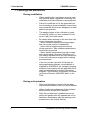
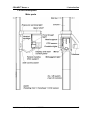
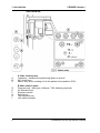
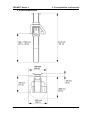
ENGLISH CRANEX® Novus e Installation and Set-up Manual 208668 rev. 2 (2012-10) CRANEX® Novus e Installation and Set-up Manual Medical Device Directive 93/42/EEC CRANEX® Novus e Installation and Set-up Manual Number 208668 Ver. 2 (2012-10) Original approved English language version Manufactured by SOREDEX, PaloDEx Group Oy. Nahkelantie 160,Tuusula P.O. BOX 148 FI-04301 Tuusula, Finland Tel. +358 (0)10 270 2000 Fax. + 358 9 701 5261 Installation and set-up manual 208668 III SOREDEX® / CRANEX® / DIGORA® / SCANORA® are registered trademarks of SOREDEX. SOREDEX endeavours to produce product documentation that is accurate and up to date. However, our policy of continual product development may result in changes to products that are not reflected in the product documentation. Therefore, this document should not be regarded as an infallible guide to current product specifications. SOREDEX maintains the right to make changes and alterations without prior notice. IV Installation and set-up manual 208668 Contents 1. Introduction...................................................................................... 1 1.1 About this manual...................................................................................... 1 1.2 Associated documentation........................................................................ 1 1.3 Warnings and precautions........................................................................ 2 During installation.................................................................................... 2 During unit operation............................................................................... 2 1.4 Unit description......................................................................................... 3 Main parts................................................................................................ 3 Unit controls............................................................................................ 4 1.5 Disposal of the transportation packaging.................................................. 5 2. Pre-installation requirements......................................................... 6 2.1 The Unit..................................................................................................... 6 2.2 The PC...................................................................................................... 8 2.3 The dental imaging software .................................................................... 8 2.4 Space requirements.................................................................................. 8 2.5 Unit dimensions......................................................................................... 9 2.6 Fixing hole dimensions............................................................................ 10 2.7 Fixing hardware and installation and setup tools.....................................11 Fixing hardware......................................................................................11 Installation tools......................................................................................11 Calibration and setup tools.....................................................................11 3. Installing the unit........................................................................... 12 3.1 Preparing the unit for installation............................................................. 12 3.2 Attaching the unit to the wall................................................................... 14 3.3 Exposure switch...................................................................................... 20 3.4 Connecting the unit to the power supply................................................. 21 3.5 Preparing the PC..................................................................................... 22 Installation and set-up manual 208668 V 3.6 Connecting the unit to the PC................................................................. 23 Connection options................................................................................ 23 Standalone ..............................................................................................................23 Network....................................................................................................................23 Connection methods............................................................................. 24 Direct Connection....................................................................................................24 IP based connection................................................................................................24 Connection using the Direct Connection method.................................. 26 Connection using the IP based method................................................. 28 Manually changing the IP address........................................................ 32 Multi-connect......................................................................................... 34 3.7 Activating the optional bitewing program................................................. 36 4. Checking the alignment and finishing the installation.............. 37 4.1 Checking the alignment of the CCD Sensor........................................... 37 4.2 Checking the image geometry (ball-pin phantom test)............................ 39 4.3 Checking the positioning lights................................................................ 41 Midsagittal light...................................................................................... 41 Frankfort light........................................................................................ 42 Focal trough light................................................................................... 42 4.4 Completing the Installation...................................................................... 43 5. Aligning the unit............................................................................ 44 5.1 Aligning the CCD sensor......................................................................... 44 5.2 Adjusting the image geometry................................................................. 46 Center ball not round............................................................................. 46 Distances between center ball and left and right balls not equal.......... 47 5.3 Aligning the positioning lights.................................................................. 49 Midsagittal and frankfort........................................................................ 49 Focal trough.......................................................................................... 51 5.4 Calibrating the CCD sensor.................................................................... 52 VI Installation and set-up manual 208668 CRANEX® Novus e 1. Introduction 1. Introduction 1.1 About this manual This manual explains how to install and set up the CRANEX® Novus e digital panoramic dental x-ray unit (the unit). You will need to operate the unit during the alignment and checking procedure. Make sure that you know how to operate the unit before starting to install and set up the unit. It is also essential that person installing and setting up the unit should have attended the manufacturer's service training course. 1.2 Associated documentation The CRANEX® Novus e User's manual. The CRANEX® Novus e Service manual (not supplied in the delivery). The installation and user manuals for the dental imaging software to be used with the unit, for example SCANORA or DIGORA® for Windows (not in the USA). Installation and set-up manual 208668 1 1. Introduction CRANEX® Novus e 1.3 Warnings and precautions During installation • When installing the unit always observe local and national safety regulation concerning the installation and use of dental x-ray equipment. • Failure to install the unit in an approved location according to these installation instructions may cause the device to be dangerous to both patient and operator. • The aperture plate in the collimator is made of lead (Pb) which is a toxic material. Do not touch it with your bare hands. • Be careful when working on the unit when the covers have been removed. - Some mechanical parts have sharp edges that can cause injuries if mishandled. - Some internal components become hot during operation. Take suitable precautions to avoid burning yourself. - Some electric components are high voltage and can be lethal if touched. Whenever you are making adjustments to the unit disconnect it from the main power supply before making the adjustment. • If the unit is to be used with a 3rd party imaging application software, not produced or supplied by SOREDEX, the 3rd party imaging software must comply with all applicable local laws and regulations on patient information software. This includes, for example, the Medical Device Directive 93/42/EEC and / or the FDA. During unit operation • Read and familiarize yourself with the warnings and precautions in the unit User's Manual. • When checking the alignment of the radiation beam protect yourself from radiation. • After the unit has been installed and set up, advise the people who will operate the unit to familiarize themselves with the warnings and precautions in the User's Manual. 2 Installation and set-up manual 208668 CRANEX® Novus e 1. Introduction 1.4 Unit description Main parts Installation and set-up manual 208668 3 1. Introduction CRANEX® Novus e Unit controls A. B. C. D. E. F. G. H. I. A. Side control panel Lights key - switches the positioning lights on and off. Up / down keys Return key, drives rotating unit to the patient in/out position (PIO) B. Main control panel Program keys - adult pan, child pan, TMJ, bitewing (optional) kV selection keys Exposure values Service key Test exposure key Unit status indicator 4 Installation and set-up manual 208668 CRANEX® Novus e 1. Introduction 1.5 Disposal of the transportation packaging The unit is transported in a corrugated cardboard box that is attached to a wooden pallet. Inside the box preformed expanded polystyrene packaging material protects the unit from shock and damage. Packaging material Weight (kg) (lb) Cardboard box and lid 21.0 46.3 Wooden pallet 7.4 16.3 Expanded polystyrene 7.6 16.8 Total weigh36.0 79.4 When disposing of the transportation packaging materials make sure that you follow all local, national and international regulations regarding the correct and safe disposal and/or recycling of these materials. Some transportation packaging materials may be non-environmentally friendly. These transportation packaging materials must be disposed of in accordance with all local, national and international regulations regarding the disposal of non-environmentally friendly materials. NOTE: It is advisable to keep some transportation packaging so that units can be repacked and easily and safely moved to new locations if required. Installation and set-up manual 208668 5 2. Pre-installation requirements CRANEX® Novus e 2. Pre-installation requirements 2.1 The Unit • The unit is supplied in one box on a pallet. The dimensions of the box with pallet are:Length Width Height 191 cm 85 cm 103 cm 76 in 34 in 41 in • The assembled unit weighs 120 kg (265 lb). Make sure that the floor where the unit is to be installed can support this weight. • The unit must be permanently attached to the wall or if this is not possible to the show stand. • If the unit is to be permanently attached to a wall make sure that the fixing hardware to be used to attach the unit to the wall and the wall itself can withstand a continuous pull-out force of at least 300 kg (660 lb). • The fixing hardware (NOT SUPPLIED) to be used to permanently attach the unit to the wall must be the correct type for the wall material. The diameter of the fixing hardware MUST be 10 mm (3/8 in). DO NOT use smaller diameter fixing hardware. • If the wall is made of thin material, you may have to use a reinforcing plate on the rear side of the wall to hold the fixing hardware. • If the wall is not strong enough to support the unit or if you are not sure if the wall will support the unit, use the show stand. 6 Installation and set-up manual 208668 CRANEX® Novus e 2. Pre-installation requirements • If the area where the unit is to be installed is subject to earthquakes, and the unit is to be permanently attached to the wall, then the base of the column must be permanently attached to the floor. The fixing hardware (NOT SUPPLIED) to be used must be the correct type for the floor and floor material. The diameter of the fixing hardware MUST be 8 mm (5/16 in). • The place where the unit is to be installed and the position from where the user will take exposures must be correctly shielded from the radiation that is generated when the unit is operated. Since radiation safety requirements vary from country to country and state to state it is the responsibility of the installer to ensure that all safety requirements are met. • Do not install the unit in environments where there are corrosive or explosive vapours. • Special steps regarding EMC need to be taken when installing the unit. For more information refer to the EMC declaration in the user's manual. • The unit must be installed at least 1.85 m (73 in) away from any non-medical electrical or electromechanical equipment. • The unit must be connected to its own dedicated power supply: - 100 to 120 VAC or - 220 to 240 VAC • Extension cables MUST NOT be used with the unit. Installation and set-up manual 208668 7 2. Pre-installation requirements CRANEX® Novus e 2.2 The PC • The PC to be used with the unit must be installed in a location that meets all local and national safety requirements with regards the connection of a PC to an x-ray device. • The connection of the unit to the PC must meet EN60601-1 requirements. The PC must be positioned at least 1.85 mm (73 in) away from the unit. • The use of ACCESSORY equipment not complying with the equivalent safety requirements of this equipment may lead to a reduced level of safety of the resulting system. Consideration relating to the choice shall include: - use of the accessory in the PATIENT VICINITY - evidence that the safety certification of the ACCESSORY has been performed in accordance to the appropriate IEC 601-1 and/or IEC 6011-1 harmonized national standard. 2.3 The dental imaging software The dental imaging software, for example SCANORA or DIGORA® for Windows (not in USA), that is installed in the PC used to with the unit must be MDD compliant . 2.4 Space requirements When installing the unit make sure that: - there is enough space at the front and sides of the unit to allow patients to enter and exit the unit easily. Patients in wheelchairs will require more space than standing patients. - the unit is positioned at least 1.85 mm (73 in) away from any non-medical electrical or electromechanical equipment. - the unit is positioned so that the operator, when protected from radiation, can see and hear the patient during an exposure. 8 Installation and set-up manual 208668 CRANEX® Novus e 2. Pre-installation requirements 2.5 Unit dimensions Installation and set-up manual 208668 9 2. Pre-installation requirements CRANEX® Novus e 2.6 Fixing hole dimensions 10 Installation and set-up manual 208668 CRANEX® Novus e 2. Pre-installation requirements 2.7 Fixing hardware and installation and setup tools The following tools and hardware are required to install and set up the unit. NOTE: THESE ARE NOT INCLUDED IN THE DELIVERY OF THE UNIT, UNLESS OTHERWISE STATED. Fixing hardware WALL attachment requires two sets of 10 mm (3/8 in) diameter fixing hardware. WALL and FLOOR attachment requires two sets of 10 mm (3/8 in) AND two sets of 8 mm (5/16 in) diameter fixing hardware. The type and length of hardware to be used will depend on the wall material and floor material to which the unit is to be attached. IMPORTANT NOTE: Fixing hardware is not required if the show stand is used. Refer to the separate instructions supplied with the show stand. Installation tools - Electric drill - Spanners (wrenches) 7, 10, 17 (two) mm AF - Hexagon socket wrenches (Allen keys) 1.5 - 8 mm - Slot blade screwdrivers 0.5 x 3mm, 0.6 x 3.5 - Torx screwdrivers T20, T25, T30 - Spirit level - Pliers and wire cutters - Scissors / Knife - Transportation wheels (pt. no. 200830) (Optional, not supplied with the unit) Calibration and setup tools - Ball-pin alignment tool (pt. no. 201916) - Test tool (line pair phantom) for countries where this calibration tool is required. (pt. no 6904430) Installation and set-up manual 208668 11 3. Installing the unit CRANEX® Novus e 3. Installing the unit 3.1 Preparing the unit for installation 1. Transport the boxed unit to the location where the unit is to be installed. 2. Remove the straps that hold the box to the pallet. 3. Lift off the top of the box and then the sides. 12 Installation and set-up manual 208668 CRANEX® Novus e 3. Installing the unit 4. Remove all the accessories, the accessory box and as much packaging material as possible. NOTE: DO NOT remove the packaging material that protects the upper shelf and the rotating unit. 5. Fold down the end of the box that is nearest the hinged section part of the column and then slide the unit over the edge of the pallet so that you can access the underside of the hinged section of the column. 6. Support the hinged column section before loosening the screws that hold it to prevent it falling and causing damage or injury. Loosen the screws (the securing nuts are inside the column) on the sides of the column that hold the hinged column section in the vertical position. Turn the hinged column section down so that it is horizontal. Secure it in position with the two screws supplied (M10 x 16), the fixing holes are on the underside (rear) of the column. Tighten the two screws (M10 x 16) on the sides of the column. Installation and set-up manual 208668 13 3. Installing the unit CRANEX® Novus e IMPORTANT NOTE: If the unit is to be attached to the show stand (pt. no. 9802666), refer to the separate installation instructions supplied with the show stand. 7. Lift the top of the column and slide the packing piece that supported it underneath so that you can access the underside of the column. Attach the two connecting rods to the two screws at the top rear of the column. Attach the wall bracket to the connecting rods with the washers and nuts. 3.2 Attaching the unit to the wall 1. CAUTION - HEAVY OBJECT A minimum of two persons are required for the following task. Transport the unit to the place where it is to be installed. NOTE: The transportation wheels (optional) are attached to the base of the column with two M10 screws and can be used to wheel the unit to the place where it is to be used. 2. Mark the position of the two fixing holes on the wall according to the dimensions given in the section 2.6 Fixing hole dimensions. 14 Installation and set-up manual 208668 CRANEX® Novus e 3. Installing the unit Alternatively, lift the unit into the position where it is to be used and then, using the wall bar as a template, mark the positions where the holes must be drilled. Hold a spirit level on the side of the column and then on the front to help to position the unit so that it is as vertical as possible. 3. Drill two holes with diameters suitable for the 10 mm (3/8 in) fixing hardware being used, and then attach the unit to the wall with the appropriate fixing hardware. Do not fully tighten the screws yet. 4. Remove the packaging material that protects the rotating unit and vertical carriage. 5. Place the spirit level widthwise on the upper shelf and level the unit in the left/right direction. Make small adjustments by loosening the wall bar fastenings and moving the top of the column to the left or the right to level the unit. Make large adjustments by moving the base of the column left or right. 6. When the unit is level in the left/right direction place the spirit level lengthwise on the upper shelf and level the unit in the forwards/backwards direction. Adjustments can be made by moving the base of the column backwards or forwards. Installation and set-up manual 208668 15 3. Installing the unit CRANEX® Novus e NOTE If the wall bracket alone does not hold the unit in position rigidly enough, or the unit is to be used in an area prone to earthquakes attach the base of the column to the floor. Make sure that the unit is level and then mark the positions of the two fixing holes on the floor and then drill two holes of a suitable size for the 8 mm (5/16 in) floor fixing hardware to be used 7. Check once more that the unit is vertical and then tighten all the fixing screws and wall bar fastenings. 8. Pull the front cover from the upper shelf and then remove the two (2) screws that hold the top cover in position and then slide it off. 9. From the upper shelf, unscrew the guide pin and two holding screws from the base plate. DO NOT remove the base plate or loosen the nuts that attach it to the unit. 16 Installation and set-up manual 208668 CRANEX® Novus e 3. Installing the unit 10.Rotate the guide pin assembly and insert it into the hole in the base plate. Note that the plain section of the guide pin must be downwards and the nut on top. IMPORTANT NOTE: If the guide pin does not fully enter the hole in the base plate (the top of bearing is NOT level with the top of the base plate) the rotating unit must be moved slightly. To do this remove the transportation screws and packing pieces (see step 12), and then slide the rotating unit gently backwards or forwards until the guide pin drops into place. Installation and set-up manual 208668 17 3. Installing the unit CRANEX® Novus e 11.Secure the guide pin in position with the two holding screws. 12.Remove the four (4) transportation screws (painted RED) and four (4) packing pieces that hold the rotating unit to the upper shelf. Now rotate the rotating unit to the Patient in/ out position (PIO). Refer to the user's manual. 18 Installation and set-up manual 208668 CRANEX® Novus e 3. Installing the unit NOTE: If the unit ever has to be relocated replace the packing pieces, transportation screws and the guide pin assembly (step 9) BEFORE removing the unit from the wall or exhibition stand. 13.Attach the covers to the bottom of the column. Attach the Front Cover, A, to the front of the column with the special long screws (4), they are inserted from the rear. Do not tighten them yet. Attach the Side Covers, B, to the sides of the column. Note that the front edge of the Side Covers is positioned between the column and the Front Cover. The rear edge is attached to the back of the column with two screws. Tighten all the screws. Installation and set-up manual 208668 19 3. Installing the unit CRANEX® Novus e 3.3 Exposure switch 1. Attach the exposure switch holder to the side of the unit using two (2) screws. If the user does not want to have the exposure switch positioned on the unit attach the exposure switch, within the range of the spiral lead, to where requested. Make sure that the eposure switch is positioned so that the user can protect themself from radiation and can see the patient during an exposure. 2. Connect the exposure switch cable to the connector at the bottom rear of the column and then place the exposure switch on the exposure switch holder. 20 Installation and set-up manual 208668 CRANEX® Novus e 3. Installing the unit 3.4 Connecting the unit to the power supply The unit must be connected to its own dedicated power supply: - 100 to 120 VAC or - 220 to 240 VAC No other equipment should be connected to the same power supply. Extension cables MUST NOT be used to connect the unit to the power supply. 1. The power supply must be equipped with circuit breaker. 2. Connect one end of the power lead to the back of the unit and the other end to the power supply. Observe any national and local electrical requirements with regards the connection of dental x-ray equipment to a power supply. Installation and set-up manual 208668 21 3. Installing the unit CRANEX® Novus e 3.5 Preparing the PC NOTE: The PC and any other external device(s) connected to the system must meet the IEC 60950 standard (minimum requirements). Devices that do not meet the IEC 60950 standard must not be connected to the system as they may pose a threat to operational safety. 1. Position the PC to be used with the unit at least 1.85 m (73 in) away from the unit. Make sure that the patient cannot touch the PC while being x-rayed NOTE: If the PC to which the unit is to be connected is to be part of a larger system make sure that all the other system components and devices are installed, connected and configured correctly. Refer to the documentation supplied with the other components and devices for information on how to do this. 2. Switch the PC on and install the dental imaging software to be used with the device. For information on how to do these refer to the installation/configuration documentation supplied with the dental imaging software. IMPORTANT NOTE: During the installation when the Select Features window appears, make sure that you select the CRANEX Novus e option. 22 Installation and set-up manual 208668 CRANEX® Novus e 3. Installing the unit 3.6 Connecting the unit to the PC The unit supports 10Base-T/100Base-TX Ethernet connections. The PC must be connected to the unit in accordance with IEC 60601-1-1. Connection options Standalone With the standalone configuration the unit is connected to a PC, and the unit then reserves the whole network interface card. The unit and PC then function as a single standalone system with no access to other networks. If it is necessary for the PC to be connected to another network the PC will require two network interface cards. Network With the network configuration the unit is connected to the PC via a network device. With this configuration the PC is connected to the unit and to other networks with a single network card. The unit is also accessible from other PC's in the same network (same subnet). For the network configuration you may need a new IP address for the unit from your local system administrator. Installation and set-up manual 208668 23 3. Installing the unit CRANEX® Novus e Connection methods The unit can be connected to the PC in two ways, Direct connection or IP based connection. Both of these connection methods allow the unit to be used in either Standalone or Network Configuration. Direct Connection Direct Connection is a connection method based on the unit serial number for establishing a connection between the unit and the PC . Direct connection is not based on IP protocol but instead utilizes a proprietary Ethernet protocol. NOTE: In some configurations the PC firewall or other network devices may prevent direct connection from operating. Direct connection requires traffic to be allowed between the PC and unit through the network devices and the PC firewall in inbound/outbound direction for Ethernet protocol ID 0x6000. If there are difficulties with the direct connection use the IP based connection method instead. IP based connection IP based connection uses IP Protocol to establish a connection between the unit and the PC. It requires the IP addresses of both the unit and the PC to be configured correctly. IMPORTANT NOTE: The default IP address of the unit is: 194.9.227.251 and the subnet mask is fixed to 255.255.255.0. The unit offers two alternatives for configuring its IP address, Remote and Manual. With the Remote alternative the unit receives its IP address from the PC. With the Manual alternative the user sets the IP address of the unit using the Graphical User Interface (GUI) of the unit. It is recommended that Remote alternative is used when configuring the IP address of the unit. However, if problems occur, due to firewalls etc., use Manual alternative instead. 24 Installation and set-up manual 208668 CRANEX® Novus e 3. Installing the unit The Remote alternative is explained as part of the section Connection using IP based connection method. The Manual alternative is explained in section Manually changing the IP address. IMPORTANT NOTE: The unit can have any IP address but the unit and PC must always be in the same subnet. For example IP for PC 194.9.227.250 and IP for the unit 194.9.227.251 and the subnet mask is fixed to 255.255.255.0. Installation and set-up manual 208668 25 3. Installing the unit CRANEX® Novus e Connection using the Direct Connection method 1. Standalone configuration. Connect one end of the Ethernet cable to the unit (the connector at the rear of the column) and the other end to the PC. Network configuration. Connect one end of the Ethernet cable to the unit (the connector at the rear of the column) and the other end to the network. 2. Switch the Unit on. 3. PC: Start the PC and then open the dental imaging software that you installed. 4. PC: SCANORA: In the Tools / Cranex Novus e Setup window select the Settings page. DfW: In the Options / Cranex Novus e Setup window select the Settings page. In the Device Connection section, click the Direct Connection radio button and then key in the complete device Serial Number of the unit (it is on the type label) into the Device serial number field. 26 Installation and set-up manual 208668 CRANEX® Novus e 3. Installing the unit Select the correct Network Interface Card (NIC) from the Computer network connection drop down list. NOTE: If there is more than one NIC in the PC make sure that you select the one that is connected to the device. Click OK to save the settings. 5. The unit will automatically connect to the PC within 5-15 seconds. Installation and set-up manual 208668 27 3. Installing the unit CRANEX® Novus e Connection using the IP based method 1. Standalone configuration: Connect one end of the Ethernet cable to the unit (the connector at the rear of the column) and the other end to the PC. Network configuration: Connect one end of the Ethernet cable to the unit (the connector at the rear of the column) and the other end to the network. 2. Switch the Unit on. 3. PC: Start the PC and then open the dental imaging software that you installed. 4. PC: SCANORA: In the Tools / Cranex Novus e Setup window select the Settings page. DfW: In the Options / Cranex Novus e Setup window select the Settings page. In the Device Connection section, click the IP based radio button to select it. Then click the Enable changing IP address check box to activate the IP-address field. 28 Installation and set-up manual 208668 CRANEX® Novus e 3. Installing the unit 5. Touch the service button on the main control panel of the unit. IMPORTANT NOTE: The unit can have any IP address but the unit and PC must always be in the same subnet. The subnet mask of the unit is fixed to 255.255.255.0. NOTE: With the network configuration the default IP address of the unit must be changed to the IP address obtained from your local IP administrator. With standalone configuration, you can avoid changing the IP address of the unit by setting the IP address of the PC to the same sub net as the default value of the unit. After changing the PC IP address in this way proceed to step 11 to finish the configuration. 6. The configuration screen will appear on the display. It shows the unit serial number, the firmware version numbers and several function buttons, IP Settings, Installation commands and, optionally, Bitewing Activation. Select IP Settings NOTE: See section 4 for information about Installation Commands and section 3.7 for information about Bitewing Activation. Installation and set-up manual 208668 29 3. Installing the unit CRANEX® Novus e 7. The IP configuration modes will appear on the screen, Remote or Manual. Select Remote. 8. The IP address window will appear which shows the current IP address of the unit. 30 Installation and set-up manual 208668 CRANEX® Novus e 3. Installing the unit 9. Standalone configuration: PC: In the IP-address field key in the desired IP address of the unit, for example 194.9.227.250, and then click the Send to Device ... button. Network configuration: PC: Key in the new IP address (obtained from the network administrator) into the IP-address field key and press the Send to Device… button. 10.The new IP address will appear on the screen. 194.9.227.250 Touch the OK button to accept the IP address and then the Arrow button to return to the main screen. 11.PC: Click the OK button to close the settings window. NOTE: If the remote IP address setting fails use the MANUAL method. See section Manually changing the IP address. Installation and set-up manual 208668 31 3. Installing the unit CRANEX® Novus e Manually changing the IP address The IP address of the unit can be changed manually. NOTE: Always set the IP address of the PC before changing the IP address of the unit. 1. Touch the service button on the main control panel of the unit. 2. The configuration screen will appear on the display. It shows the unit serial number, the firmware version numbers and several function buttons, IP Settings, Installation commands and, optionally, Bitewing Activation. Select IP Settings NOTE: See section 4 for information about Installation Commands and section 3.7 for information about Bitewing Activation. 3. The IP configuration modes will appear on the screen, Manual or Remote. Touch the Manual button. 32 Installation and set-up manual 208668 CRANEX® Novus e 3. Installing the unit 4. The Manual IP address connection screen will appear. Key in the new IP address. When the new IP address has been keyed in the OK (tick) button will become active. Touch the OK (tick) button to accept the change and return to the main display. Touch Arrow button to discard the change and return to the main display. 5. PC: SCANORA: In the Tools / Cranex Novus e Setup window select the Settings page. DfW: In the Options / Cranex Novus e Setup window select the Settings page. In the Device Connection section, click the IP based radio button to select it. Then click the Enable changing IP address check box to activate the IP-address field. 6. PC: Key in the new IP address into the IPaddress field. 194.9.227.253 7. PC: Click the OK button to close the settings window. The Ready indicator will turn green. Installation and set-up manual 208668 33 3. Installing the unit CRANEX® Novus e Multi-connect Multi-connect allows the unit to be used by several PCs within a network. A PC must "reserve" the unit before it can be used. 1. PC: SCANORA: In the Tools / Cranex Novus e Setup window select the Settings page. DfW: In the Options / Cranex Novus e Setup window select the Settings page. 2. PC: Click the Use Multi-Connect check box to select it and then, from the drop down list, select a unique Workstation identifier number (between 1 and 8) for the PC being configured. Additional workstation information, for example, user name, location etc, can be entered into the field next to the work station identifier number. The Device Autorelease timeout is the length of time that the unit will remain reserved and usable by a PC. After the set time elapses the PC automatically releases the unit so that it can be used by another PC in the network (the unit can be reserved in advance from another PC). The default setting is 300 seconds. This can be changed by keying in a new value. 34 Installation and set-up manual 208668 CRANEX® Novus e 3. Installing the unit 3. PC: Click OK to connect the PC to the unit. NOTE: An automatic technique will automatically locate the unit within the local area network and connect the PC. 4. PC: Repeat the above process for all the other PCs in the network. Make sure that you give each PC a different Workstation identifier. 5. Check the installation by starting image capture using the imaging software. If the Use Multi-Connect was selected the Workstation identifier of the PC (1 - 8) being used will appear on the unit display. Installation and set-up manual 208668 35 3. Installing the unit CRANEX® Novus e 3.7 Activating the optional bitewing program NOTE: If the Bitewing Activation button does NOT appear it indicates that the bitewing program has been installed at the factory 1. Order the bitewing License Key from SOREDEX Customer Service. The order code is 900669 Bitewing Program Upgrade. When ordering you need to give the Serial Number of the unit in which the bitewing program will be activated. SOREDEX Customer Service will e-mail the license key to you. 2. Switch on the unit and touch the service button to enter the service mode. 3. Click the Bitewing Activation button. 4. A keypad will appear which allows you to enter the license code. Enter the activation code, press OK (tick) and the bitewing program will be activated. Press the Back button twice to return to the main menu. 5. Restart the unit to activate the bitewing program. 36 Installation and set-up manual 208668 CRANEX® Novus e 4. Checking the alignment and finishing the installation 4. Checking the alignment and finishing the installation 4.1 Checking the alignment of the CCD Sensor 1. PC: Prepare the unit for an exposure. NOTE: If the dental imaging software prompts an error message "Please calibrate the device" on startup, perform CCD re-calibration as described in section 5.4. 2. Remove the chin rest. 3. Touch the service button on the main control panel of the unit to open the configuration window. 4.Select Installation Commands. 5. The PIN number screen will appear. This is a security feature to prevent the user from accidentally accessing the installation / service commands. Key in 1204 and touch the OK key. Installation and set-up manual 208668 37 4. Checking the alignment and finishing the installation CRANEX® Novus e 6. The service function will appear on the screen. Select Still Mode. 7. Protect yourself from radiation. Press and hold down the exposure switch to take an exposure. 8. PC: Use the dental imaging software to examine the image that appears. If the CCD sensor is correctly positioned the image will show a vertical black line (the beam) in the middle of a vertical light gray area (the CCD aperture). Both the beam (black line) and the CCD aperture (light gray area) must be vertical and the bottom edge of the beam (black line) must be between 0.1 and 2 mm from the bottom edge of the image. If the beam (black line) is not in the middle of the CCD aperture (the gray area) or the CCD aperture (gray area) is not vertical, the CCD sensor must be adjusted. See 5.1 Aligning the CCD sensor. 9. Touch the Arrow button to exit the Still Mode and return to the main menu. 38 Installation and set-up manual 208668 CRANEX® Novus e 4. Checking the alignment and finishing the installation 4.2 Checking the image geometry (ball-pin phantom test) 1. PC: Prepare the unit for an exposure. 2. Replace the chin rest. PAN 3. Set up the unit to take an adult panoramic exposure at 70 kV. Refer to the unit user's manual for information on how to do this. 5. Attach the ball-pin tool to the chin support. 6. Protect yourself from radiation. Press and hold down the exposure switch to take an exposure. 7. PC: Use the measuring tools in the dental imaging software to examine the dimensions of the balls that appear on the image. Magnify the image so that you can accurately measure the dimensions. Installation and set-up manual 208668 39 4. Checking the alignment and finishing the installation CRANEX® Novus e If the image geometry is correct the center ball must be round with no more than 0.2 mm difference between the horizontal diameter and the vertical diameter. Also the distance from the center ball to the furthest left-hand ball (Distance left) and the furthest right-hand ball (Distance right) must be the same, with no more than ±2.0 mm difference between them. . If the center ball is NOT ROUND and/or the distances between the balls are NOT WITHIN THE TOLERANCE, then the rotating unit (RU) or the chin rest must be adjusted. See 5.2 Adjusting the image geometry. IMPORTANT NOTE: In some cases you may have to adjust the position of both the rotating unit AND the chin rest. 40 Installation and set-up manual 208668 CRANEX® Novus e 4. Checking the alignment and finishing the installation 4.3 Checking the positioning lights Midsagittal light 1. Attach the chinrest and a rod to the support holder. Press the light button to switch the patient positioning lights on. The light beam must be vertical and strike the center of the rod If the beam is not in the correct position it must be adjusted. See 5.3 Adjusting the positioning lights. Installation and set-up manual 208668 41 4. Checking the alignment and finishing the installation CRANEX® Novus e Frankfort light 1. Draw a horizontal line on a sheet of paper parallel to one side. Remove the chin rest and hold the piece of paper on the chin rest support 2. Press the light key. The frankfort light must be parallel to the line on the piece of paper. If the beam is not in the correct position it must be adjusted. See 5.3 Adjusting the positioning lights. Focal trough light 1. Attach the ball phantom to the support holder. 2. Press the light button to switch the patient positioning lights on. The light beam must strike the line that crosses the ball phantom If the beam is not in the correct position it must be adjusted. See 5.3 Adjusting the positioning lights. 42 Installation and set-up manual 208668 CRANEX® Novus e 4. Checking the alignment and finishing the installation 4.4 Completing the Installation Check that the unit functions correctly: - Take a test exposure to verify that the unit operates correctly and the image is transferred successfully to the PC. Protect yourself from radiation when taking the exposure. - Check the up/down keys drive the unit up and down. - Check that the light key switches the positioning lights on and off. - Check that the lights come on when the mirror is opened. - Check that when the emergency switch is pressed the unit stops operating. Finally replace all the covers that were removed. Installation and set-up manual 208668 43 5. Aligning the unit CRANEX® Novus e 5. Aligning the unit 5.1 Aligning the CCD sensor If the sensor was not correctly aligned after carrying out the alignment check (4.1 Checking the alignment of the CCD Sensor) the sensor must be repositioned and new beam images taken to confirm that it is correctly positioned. 1. Remove the inner sensor cover from the rotating unit, it is held in place with four (4) screws 2. To adjust the CCD sensor loosen the four nuts (A) that hold the CCD sensor in place and then adjust its position with the two screws (B) on the left-hand side. 44 Installation and set-up manual 208668 CRANEX® Novus e 5. Aligning the unit Adjust and recheck the position of the CCD sensor until the beam is vertical and centered in the middle of the CCD aperture. 3. Touch the Arrow button to exit the Still Mode and return to the main menu. Installation and set-up manual 208668 45 5. Aligning the unit CRANEX® Novus e 5.2 Adjusting the image geometry IMPORTANT NOTE: In some cases you may have to adjust the position of both the rotating unit AND the chin rest. Center ball not round If the center ball is NOT ROUND then the position of the rotating unit (RU) must be must be adjusted. 1. Loosen the two nuts that hold the guide pin assembly in place. Turn the adjusting nut counter clockwise to move the rotating unit towards the column and clockwise to move it away from the column. 46 Installation and set-up manual 208668 CRANEX® Novus e 5. Aligning the unit 2. Re-tighten the guide pin assembly nuts after the adjustment. 3. Take another ball-pin exposure to confirm the center ball is round. Also verify that the distances from center ball to left and right pins are equal, if not proceed to the next section, Distances between left and right pins not equal. Distances between center ball and left and right balls not equal If the distances between the center ball and the left and right balls are DIFFERENT then the chin support (CS) must be must be adjusted. 1. To adjust the chin support, first remove the Chin Support Holder (1 screw accessible from the underside of the patient support handle). Set screw 2. Loosen the set screw that holds the Lower Shelf Screw (the horizontal screw) in position and turn it to adjust the position of the Chin Support Holder. Installation and set-up manual 208668 47 5. Aligning the unit CRANEX® Novus e If the right-hand distance is greater that the left (C), move the chin rest to the left. If the left-hand distance is greater that the right (D), move the chin rest to the right. CAUTION: DO NOT loosen the screws (2) that attach the Chin Support Holder to the Patient Handle. 3. Take another ball-pin exposure to confirm the unit is now correctly aligned. Readjust if required. 4. After the adjustment has been done retighten the set screw and replace the Chin Support Holder. 48 Installation and set-up manual 208668 CRANEX® Novus e 5. Aligning the unit 5.3 Aligning the positioning lights Midsagittal and frankfort 1. Remove the corner piece, it pulls off. 2. Remove the lower cover (2 screws). The midsagittal light can now be accessed and adjusted, see step 5. Installation and set-up manual 208668 49 5. Aligning the unit CRANEX® Novus e 3. To access the frankfort light remove the side profile left assembly (4 screws). CAUTION: Be careful not to damage the flat cables that attach the exposure warning light and control panel to the unit. 4. Remove the mirror assembly. It is held in place with 6 screws located behind the mirror. 5. Both the midsagittal and frankfort lights have similar adjusting mechanisms. Loosen the clamping screw on the light module and rotate the light to position beam vertically. For left/ right beam movements loosen the nuts/screws that hold the light module bracket in position and adjust the laser lights accordingly. 50 Installation and set-up manual 208668 CRANEX® Novus e 5. Aligning the unit Focal trough 1. Loosen the five (5) screws that hold the sensor inner cover in place and then remove the cover. 2. Loosen the clamping screw on the light module and then rotate the light to position beam vertically. To adjust the beam in the up/down left/right directions loosen the nuts/screws that hold the light module bracket in position and adjust the laser lights accordingly. . Installation and set-up manual 208668 51 5. Aligning the unit CRANEX® Novus e 5.4 Calibrating the CCD sensor NOTE! The CCD sensor is calibrated at the factory and thus does not normally need to be calibrated again. However, if the dental imaging software prompts an error message "Please calibrate the device" on startup, perform CCD re-calibration as instructed below. 1. PC: Prepare the unit for an exposure. 2. Touch the service button on the main control panel of the unit to open the configuration window. 3. Select Installation Commands. 4. The personal identification number (PIN) screen will appear. Key in 1204 and touch the OK key. Then select Image Calibration. 5. Remove the chin rest and make sure that there is nothing between the sensor and tubehead. 52 Installation and set-up manual 208668 CRANEX® Novus e 5. Aligning the unit 6. Protect yourself from radiation, and take an exposure. 7. PC: Use the dental imaging software to examine the image. It should be evenly grey all over with no granularity nor horizontal lines/stripes. If the image is not evenly gray repeat the calibration until it is. If artefacts appear on the image make sure that there is nothing between the sensor and the tubehead. 8. Touch the Arrow button to exit Image Calibration. Installation and set-up manual 208668 53