1
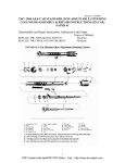
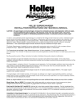
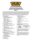
INSTALLATION INSTRUCTIONS
FOR MODELS 4165 & 4175
R-6210-3 & R-8679
TO PRESERVE YOUR WARRANTY, THESE INSTRUCTIONS MUST BE READ THROUGHLY AND
COMPLETELY BEFORE AND DURING INSTALLATION.
The 6210-3 and 8679 carburetors have been designated and calibrated as direct “bolt on” replacement carburetors for 1965-1970 Chevrolet
passenger vehicles (only) originally equipped with a Rochester Quadra-Jet carburetor. (Specific recommendations and descriptions for each
carburetor list number are shown in the accompanying chart on the last page of the instruction sheet.)
NOTE: Use of these carburetors on other G.M. or Chrysler applications with spreadbore intake manifolds and/or Rochester Quadro-Jet
carburetors will probably result in poor engine performance. This results from the fact that carburetors intended for use on other
applications have different requirements in the area of fuel delivery rate, gasket sealing characteristics, ignition spark advance, choke
operation, and power enrichment. Holley Carburetor division cannot and will not be responsible for any actual or alleged engine or
other damage or injury that results from misapplication (voids warranty) of any of the carburetors listed above. If you are in doubt about
proper carburetor applications, consult the Holley catalog. If for some reason, you have purchased the wrong carburetor for your
application, return it to your dealer (before installation) and get the proper carburetor. No warranty will be issued for any misapplication
once the carburetor has been installed. Some parts provided with the carburetor might not be used on your installation. Extra parts
have been provided because the parts that are required for one model year might be different from those of another year.
INSTALLATION INSTRUCTIONS:
1.
Remove the air cleaner, carefully disconnecting any vacuum lines. Mark these lines, so they can be reassembled to the cleaner in the
same manner.
2.
Remove the existing carburetor by following the procedure outlined below:
A. Remove the steel fuel line fitting carefully.
B. Remove the throttle linkage and automatic transmission controls at the throttle lever. Remove the throttle return spring, noting how
the spring is anchored.
C. Remove the PCV hose from the front of the carburetor.
D. Remove the spark advance hose(s), noting that the left upper front is a manifold vacuum attachment and the right lower front is a
“timed” vacuum attachment (if so equipped).
E. Remove the fresh air hose from the upper rear of the carburetor (if so equipped), noting it as the fresh air hose.
F. Remove the gulp valve hose (only found on some California cars equipped with A.I.R. emission control systems) from the lower rear
of the carburetor.
G. Detach the choke rod from the original carburetor. Be sure to note how it “pulls” to close the choke plate or whether it “pushes” to
close the choke plate. See Illustration 7.
H. Remove two (2) front attaching bolts and two (2) rear attaching nuts. Lift free the linkage bracket (if so equipped), located at the right
rear attaching nut, and remove the carburetor by lifting straight up.
I.
Remove all original manifold studs. Insert the four (4) studs provided. New studs should be threaded securely into the manifold.
3.
WARNING: Use the proper gaskets! Three (3) types of gasketing will be found on the vehicles for which this carburetor is designed:
Illustration 1
NOTE: See Illustration 9.
Illustration 2
A.
B.
C.
A steel reinforced gasket plus a thin stainless steel plate (used to cover the exhaust heat track or slot in the front of the intake
manifold) can be found. Carefully remove both the steel plate and the gasket. Clean the manifold surface. Install the new gasket
supplied with the carburetor (See Illustration 1, gasket B). Reinstall the steel plate (See Illustration 2). The thin gasket found in the
carburetor should not be used. A new stainless steel plate can be purchased under Holley P/N 108-20. NOTE: See Illustration 9.
If there is a large aluminum and fiber heat shield that extends well beyond the throttle body, this must remain in place. The gasket
packed with the carburetor is placed on top of the heat shield. See Illustration 1, gasket A.
If there is a standard type gasket with no extra metal gasket or heat shield, replace this with the thin one supplied with the carburetor.
See Illustration 1, gasket A.
Illustration 3
4.
To install the new Holley carburetor, the following procedure is suggested prior to assembly on the manifold:
A. Assemble to the Holley throttle lever in the appropriate locations (this can be determined by comparison with the original carburetor)
any balls or lever extensions that were used on the original carburetor. If a ball exists on the original carburetor lever that cannot be
removed, a corresponding ball can be found in the parts package. See Illustration 3.
B. For 1966 and 1967 “California Only” vehicles, the sealing plug in the rear gulp valve tube must be removed (use screwdriver) before
the carburetor is placed on the manifold. (See Illustrations 4 & 5). These carburetors have been produced using two different throttle
body designs. If your unit does not have the gulp valve tube cast integrally in the throttle body (i.e. if it looks like Illustration 5), it will
be necessary to remove the sealing plug with a screwdriver. Install a 1/8” close nipple and 1/8” pipe coupler to provide a mount for
the gulp valve hose. See Illustration 6.
Illustration 4
Illustration 5
Illustration 6
WARNING: Do not overtighten the close nipple and/or pipe coupler because it can crack the throttle body.
C.
5.
On late model “big” block engines, the lower portion of the primary throttle lever may have to be removed. This is determined by
placing the carburetor on the manifold and operating the throttle lever to the wide-open position. If the lower part interferes, remove
the two screws holding the lower lever on and remove the lower lever. See Illustration 3.
Place the carburetor on the manifold. Reposition the throttle bracket, if used. (NOTE: On some applications, the throttle cable mounting
bracket must have a corner removed to allow it to be reassembled on the mounting stud). Install nuts on the top threads only until all nuts
have been started. This allows the carburetor to be shifted to facilitate nut installation. Cross tighten the mounting nuts alternately.
WARNING: Overtightening may result in warped or cracked carburetor bodies.
6.
Reconnect the throttle and transmission linkage and throttle return spring. Operate the linkage to assure correct travel by opening to wide
open throttle. Operate the linkage from inside the vehicle and have someone check to assure complete opening of the throttle plates.
Readjust the throttle bracket/cable, if necessary. Readjust the throttle operated transmission switch, if necessary (automatic transmission
vehicles only). Check the chassis service manual for proper adjustment procedures.
WARNING: Check the assembled linkage to make sure that there is no binding or sticking during any part of throttle operation. A binding
throttle could result in uncontrolled engine speed.
7.
Reconnect the choke rod, installing in the rear hole to pull close and in the front hole to push close. Operate the choke link to assure free
choke travel (holding the throttle lever partially open). See Illustration 7.
Illustration 7
8.
Reconnect the appropriate hoses to the carburetor, noting the correct fitting from Illustrations 4 & 7. Plug any ports that are not used with
the rubber plugs provided.
9.
Reconnect the fuel line to the front of the carburetor. CAUTION: In some cases, it may be necessary to reform the line to align with the
carburetor fitting. DO NOT induce any sharp bends.
10. Remove the air cleaner stud from the original carburetor and install it on the new carburetor.
11. On A.I.R. (air pump) equipped vehicles, connect the air pump control valve sense line to one of the manifold vacuum sources provided.
Connect the gulp valve hose to the rear of the vehicle, if so equipped.
12. Recheck all the vacuum hoses to assure they are attached properly. Carburetor fittings that are not used are capped with the rubber plugs
provided.
13. Start the engine and check the fuel inlet fitting for fuel leaks.
14. Preset the idle mixture as follows:
A. Open the idle needles to full rich position (counterclockwise). DO NOT remove the idler limiter caps.
B. Preset each needle as follows:
1. 327-350 engines 1/2 turn in from full rich.
2. 396-402 engines 1/4 turn in from full rich.
15. Set the idle speed to the manufacturer’s specification on the tag in the engine compartment or from the appropriate service manual. If the
above data is unavailable, use the following guidelines: NOTE: Always set the idle speed with the parking brake on.
All Automatic Transmissions—600 R.P.M. in drive
All 396-427 Manual—800 R.P.M. in neutral
All Other Manuals—700 R.P.M. in neutral
NOTE: Use only the carburetor speed screw to achieve this speed. If idle quality is unacceptable at this setting, the idle mixture may be
adjusted a MAXIMUM OF 1/4 TURN FROM THE INITIAL SETTING.
It is preferable to use an exhaust gas C.O. (carbon monoxide) analyzer to achieve these settings.
Idle settings should not exceed 1.0% CO on 68’-69’ vehicles and .5% on 70 vehicles to assure compliance with Federal Emission
Standards.
SPECIAL AIR CLEANERS
Some air cleaners require slight rotation for installation and the cleaner locator should be modified accordingly. Connect the vacuum hose.
1. For high performance open-element cleaners, the clean air tube elbow must be removed from the lower tray and the resulting hole plugged
with a plug provided. Connect the rocker cover hose to the new adapter elbow, as in Illustration 8. Adapters may be purchased as Holley
P/N 17-8.
2.
For Cowl induction cleaners, replace the spacer from the original carburetor with Holley spacer P/N 17-13. For special Cowl induction
Camaros, remove the upper portion of the cleaner ring and discard. Install the cleaner spacer onto the carburetor and reinstall the cleaner.
Illustration 8
Illustration 9
NOTICE: Holley Model 4165 (spreadbore) carburetors that have carbon deposits in the areas shown by the arrows will not be accepted for
warranty. The deposit is evidence of improper installation (not using the stainless steel plate where required) for which Holley cannot
assume liability.
WARNING: Inadequate clearance between the air cleaner and the throttle lever could result in uncontrolled engine speed.
CAUTION: Check the clearance between the air cleaner and the hood before closing the hood completely.
OPERATING INSTRUCTIONS
1.
Cold Starting Procedures:
For cold engines, the following steps should be followed:
A. Depress the accelerator pedal to the floor and allow it to return to normal position (this charges the manifold with fuel and sets the
choke).
B. With the foot off the pedal, crank the engine until it fires.
C. Repeat steps A and B should the engine fail to run after the initial start. As indicated in the manufacturer’s operating instruction
manual, full power operation is not recommended until the engine reaches the correct operating temperature.
2.
Fast Idle Speeds:
The factory setting on fast idle speeds for these carburetors is adequate for the majority of vehicles. Should the particular application
require adjustment, the following procedure should be used:
A. With the engine running and in neutral, advance the throttle and place the fast idle cam such that the fast idle speed screw contacts
the top step of the cam. On this step, set 1600 RPM with the engine warm.
B. If step A is correctly set, the idle speed on the last or low step of the cam will be 1200 or 1300 RPM.
MAINTENANCE WARNING: Fuel system components, including fuel lines and the carburetor, should be inspected periodically to assure no
fuel leakage and the soundness of hoses. Today’s controlled emissions engines provide higher temperatures in the engine compartment.
These high temperatures promote faster aging of non-metallic materials.
Hoses that exhibit surface cracks when bent to a 180° position should be replaced. The presence of liquid fuel demands tightening of the
fittings, hose replacement, and retorquing of the fuel system component flange nuts (where applicable). Tightening of carburetor fuel bowl
screws should provide 25-30 in./lbs. of torque in a clockwise direction. Periodically, recheck the torque of the fuel bowl screws, such as at
regular maintenance intervals.
GENERAL
Correct engine timing, spark plug gaps and heat range, distributor point condition and gap, condenser and wiring, valve lash, condition of PCV
valve, and correct operation of the exhaust heat valve are very important to the optimum efficiency and performance.
For additional information, consult the Holley Carburetor and Manifolds (H.P. Books) and the Holley Service Guide No. 2.
Holley Carburetor Features and Recommendations:
Divorced*
Hand
Center Inlet
Single Inlet Side-Pivot
Vacuum
Emission
Recommendation
Choke
Choke
“Dual-Feed” (Fuel
Floats (No External Fuel
Sec.
Compliance
Level) Adjustment
Level Adjust.)
(1965-1970)
0-6210
X
X
X
1965-1970
(650 CFM)
327-402 CID
0-8679
X
X
X
X
1965-1970
(650 CFM)
327-402 CID
*Due to casting requirements for the divorced choke, carburetors equipped with divorced chokes cannot be converted to hand chokes.
Copyright © 1992
Printed in U.S.A.
199R-8020-3
Holley
Performance Products Inc.