1
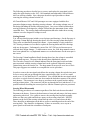
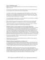
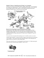
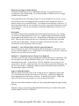
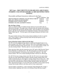
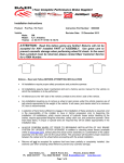
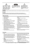
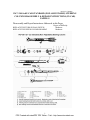
Revised: 17JA2009
1967–1968 A&F-CAR STANDARD (NON-ADJUSTABLE) STEERING
COLUMN DISASSEMBLY & REPAIR INSTRUCTIONS (IN-CAR)
PAPER #1
Disassembly and Repair Instructions Addressed in this Paper
REPLACE THE TURN SIGNAL SWITCH
REPLACE THE UPPER COLUMN BEARING
Degree of Difficulty
Moderate
Moderate
1
PDF Created with deskPDF PDF Writer - Trial :: http://www.docudesk.com
The following procedures describe how to remove and replace the turn signal switch
and/or the upper bearing on the 1967–1968 standard (non-adjustable) General Motors
A&F-car steering columns. Note, this paper describes repair procedures without
removing the steering column from the car.
All General Motors 1967 and 1968 passenger cars came equipped with the first
generation Saginaw energy absorbing steering columns. All steering columns were of
this design (including tilt and the telescoping types). In a severe frontal collision these
steering columns were designed to collapse forward into the instrument cluster with a
controlled force. The steering shafts and transmission shift tubes inside these steering
columns were also designed to collapse as well.
Getting Started
You will note that this paper includes several pictures and drawings. On the first page is
a Steering Column Blowup drawing that shows all of the steering column detail parts.
These parts are identified by numerical callouts. A great number of early production
1967 steering columns were recalled to replace the steering shafts and lower bearings
with new design parts. Unfortunately, most of the 1967 GM service literature never
reflected these design changes. To make matters worse, the 1968 shop manuals seem to
have been updated in a very haphazard manner so even that literature for the most part is
not correct.
The Steering Column Installation Detail drawing shows how the column is assembled
into the dash structure. The parts in this drawing have alphabetical callouts.
The Chevrolet Chassis Service Manual indicates that the turn signal switch and other
parts associated with the steering column head can be replaced without the steering
column being removed from the car. The shop manual is not specific as to how to do it.
This paper suggests two methods to accomplish the service procedure.
In order to remove the turn signal switch from the steering column, the switch wires must
be free to move and pass up through the large capsule bracket (M), as well as a small
metal cover #15, the shift bowl #12, and shroud. You will find that the turn signal switch
wires have a curved electrical connector down under the dash that connects to the vehicle
body harness. This connector is too large to pass between the capsule bracket and the
steering column jacket. (The connector will pass up through the bowl and shroud.) Two
possible methods describing the removal process with the column in place are presented.
Steering Wheel Disassembly
The following procedures are common regardless of the final switch removal method.
Disconnect the battery. Remove the horn button or horn pad and remove the horn contact
and steering wheel nut. Use a puller to remove the steering wheel and hub assembly.
Make sure that your puller and bolts are square to the steering wheel hub. NEVER,
hammer on the end of the steering column shaft in order to try and release the hub.
There should be an indentation on the hub as well as a matching mark on the end of the
steering shaft. They should be in alignment. If there are no marks, use a crayon or
grease pencil to the mark the orientation of both parts.
2
PDF Created with deskPDF PDF Writer - Trial :: http://www.docudesk.com
Upper Column Disassembly
Remove the screws holding the plastic trim cover from under the instrument panel and
remove the cover.
On Chevelle steering columns with a column shift automatic, remove the indicator wire
by removing the screw at the bottom of the steering column.
On Camaro steering columns with automatic trans and the shift lever on the column,
remove the screws securing the PRNDL dial retainer and dial and remove them. Slide
the indicator out of the shift bowl and remove the indicator. Remove the cap and bulb
from the turn signal switch housing if so equipped.
On steering columns with the shift lever on the column, drive out the shift lever retaining
pin from the shift bowl #12 and remove the lever.
Slide the upper bearing preload spring and the canceling cam off of the steering shaft.
Remove the turn signal lever screw and remove the lever. Push the hazard warning
switch in, then unscrew and remove the hazard knob. Remove the c-clip #3, the thrust
washer #4, and the wave washer #5 from the steering column shaft.
Method #1–Remove Curved Connector from Turn Signal Switch Wires
Go down under the dash and disconnect the curved turn signal switch connector from the
vehicle body harness. Use the wire from a heavy paper clip or use a very thin blade
screwdriver and insert it into the connector from the contact side to disengage each wire
and contact. There should be a small molded square channel in the connector that will
guide you to a metal tang on the contact that holds it in place. Once you depress the tang
and the wire and contact should come right out of the connector. You should take a small
knife blade and bend the tang back out so that it will engage the connector correctly when
the parts are reassembled. Make sure that you note the wire locations so that you will
reinstall them in the correct order.
Without the curved turn signal switch connector the wires will be free to pass right up
and out of the steering column.
Method #2- Remove Capsule Bracket & Wiring Cover
Go down under the dash and unfasten the four bolts that hold the capsule bracket (M) to
the steering column jacket. Then remove the two nuts (F) and the forward bolt (H) and
washer that hold the capsule bracket up into the instrument panel. Don’t lose the wedge
(G) that is sandwiched between the capsule bracket and the dash bracket by bolt (H).
IMPORTANT: With the capsule bracket removed the steering column will not be
supported up into the instrument panel. The steering column should NEVER be allowed
to just hang cantilevered under the dash (held only by the attachments at the floor and the
flexible coupling). Allowing the steering column to hang will place very large loads on
the lower column bearing #19 and the mast jacket #14 which could cause failure.
3
PDF Created with deskPDF PDF Writer - Trial :: http://www.docudesk.com
Method #2- Remove Capsule Bracket & Wiring Cover (Continued)
Therefore you must have an assistant hold the steering column in place or you must prop
the column in its original position. Once the capsule bracket and the cover are removed,
the turn signal switch wires and connector can be pulled up through the shift bowl
housing #12 and the shroud. Proceed to the next procedure.
Removal of the Turn Signal Switch & Bearing Housing Assembly
Most people get a little frustrated while taking apart or reassembling the 1967-68
standard steering column because they don't realize that turn signal switch #6 and the
attached bearing assembly #7, cover #8, and plate #10 are all attached together. They
“cam lock” into the steering column jacket #16 and all come off together as a unit (see
picture below).
Loosen the three turn signal switch mounting screws #2 until the switch cover can be
rotated counter-clockwise. It may be necessary to push on top of the screws to loosen the
cover assembly. Lift the whole switch and attached housing off, while pulling the turn
signal switch wires up and out of the steering column.
Then remove the three screws #2 and springs #9 from the plate #10. Finish removing the
turn signal switch from the bearing assembly #7 and cover #8.
4
PDF Created with deskPDF PDF Writer - Trial :: http://www.docudesk.com
Replacing the Upper Column Bearing
The upper column bearing is part of the bearing housing. It is a press fit from the
steering wheel side of the housing. The GM part number is 7800269 and it is no longer
available from GM dealers.
The bearing that is part of bearing assembly #7 was not designed to be serviced. It was a
press fit into the die cast housing and there is a thin lip on the housing bore that was
staked or spun over to retain the bearing. The bearing has been known to come loose. If
this is the problem that you are correcting, you can try to epoxy glue the bearing case into
the housing bore. You can also attempt to carefully peen limited areas of the case over
on the bearing.
Reassembly
Assemble the upper bearing assembly and the turn signal switch into the cover, feeding
the switch wires through the back of the cover. Align the signal switch and the bearing
housing holes with the holes in the cover. Install the three mounting screws through the
holes. Slide the three springs onto the screw ends and place the lock plate in position
over the screws and springs. Turn the screws three turns into the lock plate. (There
should still be a little movement of the lock plate.)
Method #1 – Curved Turn Signal Switch Connector Removed
Feed a length of the switch wires through the shift bowl housing #13 and shroud. Feed
the loose ends through the cover. Reinstall the curved connector on the wires. Make sure
that the wires are in the correct location.
Method #2 – Capsule Bracket & Wiring Cover Removed
Feed the switch wires and connector through the shift bowl housing #13 and shroud. Pull
the turn signal wires flat and reinstall the metal cover. Set the capsule bracket in place
and install the four bolts. Torque them to 15 ft-lbs. Install the two rear nuts (F) and
torque them to 20 ft-lbs. Insert the wedge (G) to the distance required to fill the gap. Do
not force it any further. Holding the wedge in position, install the capsule bracket bolt
(H) and washer, tighten to 20 ft-lbs.
Upper Column Reassembly
Place the signal switch unit on top of the column jacket #14, aligning the tangs on the
I.D. of the lock plate with the slots in the top of the jacket. Push the turn signal unit
down applying pressure and twist it clockwise. It should lock into place. Tighten the
three screws in a criss-cross sequence to avoid cocking the lock plate.
Slide the wave washer and thrust washer over the steering shaft against the upper bearing
housing.
Slide the C-ring over the steering shaft and install it into the groove in the steering shaft.
MAKE SURE IT IS FULLY SEATED!
5
PDF Created with deskPDF PDF Writer - Trial :: http://www.docudesk.com
Upper Column Reassembly (Continued)
Place the turn signal lever in position and secure it with a screw. Screw the hazard
warning button into place.
On Camaros so equipped, install the bulb and cap. Install indicator into shift bowl.
Install dial and retainer with screws.
Reinstall shift lever and drive retaining pin to hold it in place if required.
The steering column position inside the vehicle body should not have changed during the
previous procedures. Therefore, it should not be necessary to realign the steering column
to the flexible coupling on the gear.
Snap the turn signal wire connector into the vehicle body harness.
Reattach the shift indicator pointer if so equipped. Reattach the plastic trim cover under
the instrument panel.
Caution: The turn signal switch must be in the neutral position when assembling
the canceling cam. Slide the canceling cam and upper bearing preload spring onto end
of the steering shaft.
Align the mark on the steering wheel hub with the steering shaft. Reinstall the steering
wheel and hub, torque the steering wheel nut to 35 ft-lbs. Reinstall the horn button or
pad.
Reconnect the battery.
[email protected]
67-68A&FStdColumnD&R1Rev17JA2009.doc
6
PDF Created with deskPDF PDF Writer - Trial :: http://www.docudesk.com