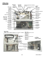
1
Installation, Operation,
Technical Service and
Replacement Parts Manual
_______________________
Ice Cube Makers
GT36x, GT56x, GB56x,
GB106x
_______________________
Stacking Instructions
Multiple GB56x or GB106x
_______________________
Ice Cube Crushers
T27x
_______________________
Pre-charged Remote AirCooled Condenser
RC214APV
_______________________
KDIndustries, Inc.
1525 East Lake Road
Erie. PA 16511-1088 U.S.A.
(800) 840-9577
FAX: (800) 548-9392
www.kold-draft.com
September 2010
KOLD-DRAFT
Installation, Operation, Technical Service Specifications and Replacement Parts Manual
Ice Cube Makers
GT36x, GT56x GB56x, GB106x
Stacking Instructions
Multiple GB56x or Multiple GB106x
Ice Cube Crushers
T27x
Pre-charged Remote Air-Cooled Condenser
RC214APV (For GB106xR)
Copyright 2010 KDIndustries
Unauthorized reproduction of this manual is freely permitted for all purposes except for monetary
gain.
It is not guaranteed that this service manual is up to date, technically correct, complete, or free from
writing problems or that the product is free from minor flaws or that it meets the needs of the
customer.
September 16, 2010
-2-
KOLD-DRAFT
Table of Contents
Safety Information ................................................................................................................................. 5
Ice Maker Identification ......................................................................................................................... 6
Serial Number Plate Location ............................................................................................................ 6
Date Code Key .................................................................................................................................. 6
Model Number Key ............................................................................................................................ 7
Installation ............................................................................................................................................. 8
Pre-Install Checklist ........................................................................................................................... 8
Additional Pre-install Information for Cooling Tower Applications (L models).................................. 10
Assembly ............................................................................................................................................ 10
Unpacking ....................................................................................................................................... 10
Assembly Procedure ....................................................................................................................... 10
Rear Deflectors: .................................................................................................................................. 12
Initial Start Procedure ......................................................................................................................... 12
Ice Machine Cleaning Procedure ........................................................................................................ 13
Specifications ...................................................................................................................................... 15
Machine Capacities ......................................................................................................................... 15
Electrical Use and Machine Dimensions/Weight ............................................................................. 16
Water Fill Levels, Cycle Times and Harvest Weights ...................................................................... 17
Cube Information ............................................................................................................................. 17
Typical Refrigerant Operating Pressures......................................................................................... 17
Components........................................................................................................................................ 17
Mechanical Components ................................................................................................................. 17
GB106x Series Unique Components ............................................................................................... 21
Controller ......................................................................................................................................... 22
Sequence of Operation ....................................................................................................................... 24
Ice Making Sequence ...................................................................................................................... 24
Ice Bin Full/Cleaning Mode.............................................................................................................. 25
Description of Each Process ........................................................................................................... 25
Fill ................................................................................................................................................ 25
Freeze.......................................................................................................................................... 25
Lower ........................................................................................................................................... 25
Harvest ........................................................................................................................................ 26
Raise............................................................................................................................................ 26
Ice Bin Full ................................................................................................................................... 26
Cleaning Mode............................................................................................................................. 26
Abnormal-Water Plate Re-Opens ................................................................................................ 26
Shutdown-High Pressure ............................................................................................................. 26
Start Methods...................................................................................................................................... 26
Ice Making Mode Start Up ............................................................................................................... 26
Cleaning Mode Start Up .................................................................................................................. 27
GT36x, GT56x, GB56x Wiring Diagram .............................................................................................. 28
GB1064 A & L Wiring Diagram ........................................................................................................... 29
GB106xR Wiring Diagram ................................................................................................................... 30
Compressor Test Procedure ............................................................................................................... 31
Test Procedure for a Short Circuit to Ground (Ground Fault) .......................................................... 32
Test Procedure for Continuity And Proper Resistance .................................................................... 32
Test Procedure for Compressor Electrical Components ................................................................. 33
Testing The Run Capacitor:............................................................................................................. 33
Testing The Start Capacitor:............................................................................................................ 33
-3-
KOLD-DRAFT
Additional Service Information ......................................................................................................... 34
Water Plate Up/Down Position and Adjustment .................................................................................. 34
Water Plate Alignment ........................................................................................................................ 36
Web Thickness Adjustment................................................................................................................. 37
Actuator Motor Electrical Tests ........................................................................................................... 37
Probe Test Procedure ......................................................................................................................... 38
Water Plate Replacement ................................................................................................................... 39
Instructions For GB1064 Water Fill Adjustment .................................................................................. 40
Troubleshooting .................................................................................................................................. 42
Parts Diagrams ................................................................................................................................... 47
GT36x Parts .................................................................................................................................... 47
GT56x Parts .................................................................................................................................... 48
GB56x Parts .................................................................................................................................... 49
GB106x Parts .................................................................................................................................. 50
Parts List ............................................................................................................................................. 52
Stacking Instructions ........................................................................................................................... 56
Installation, Operation, Technical Service and Replacement Parts Manual ........................................ 59
Ice Crusher Installation ....................................................................................................................... 60
Pre-Install Checklist ......................................................................................................................... 61
Assembly/Installation ....................................................................................................................... 61
Initial Start-Up.................................................................................................................................. 66
Crusher Operation .............................................................................................................................. 66
Ice Crusher Cleaning Procedure ......................................................................................................... 67
Adjustment And Lubrication ................................................................................................................ 67
Wiring Diagram ................................................................................................................................... 68
Pre-Charged Remote Air Cooled Condenser Installation .................................................................... 69
Installation ........................................................................................................................................... 70
Pre-Install checklist ......................................................................................................................... 70
Installation ....................................................................................................................................... 70
Specifications .................................................................................................................................. 71
Minimum Total Charge Required ..................................................................................................... 71
Electrical Information ....................................................................................................................... 73
Removing From Service .................................................................................................................. 73
-4-
KOLD-DRAFT
Safety Information
Special attention should be given to potential hazard labeling on the equipment and the signal words
and symbols that are used throughout this manual.
Note: Note is used to notify personnel of installation, operation or maintenance information which is
important, but not a cause of personal injury or property damage.
Warning:
Indicates a potentially hazardous situation that could cause death or serious injury.
Caution:
Indicates a potentially hazardous situation that could result in minor or moderate
injury. It may also be used to alert against unsafe practices
Danger:
Indicates that an imminently hazardous situation exists, which, if not avoided, will
result in death or serious injury.
Note:
Check for freight damage before proceeding with the equipment installation. Be sure to
inspect the equipment carefully for any damage that may not have been evident on the outside
of the carton. Contact the freight carrier immediately to report any damage and file a claim.
Read the entire manual before installing, operating or servicing the machine
To ensure optimal efficiency and productivity follow these installation instructions exactly.
All machines have been tested and adjusted for correct performance at the factory.
Knowledge of proper installation and service procedures is essential for the safe operation and
maintenance of KOLD-DRAFT equipment. Refer all installation and service work to qualified
technicians.
This equipment must be installed in compliance with the applicable federal, state/province,
and/or local plumbing, electrical, and health/sanitation codes and requirements.
Always disconnect the power supply before servicing the equipment or when the equipment
will not be used for a period of time. Some circuits remain energized when the machine is
switched off.
Never operate equipment that has been damaged or does not have all the protective covers in
place.
Never operate equipment that has been altered from the original KOLD-DRAFT specifications.
Use of non-approved parts when servicing KOLD-DRAFT equipment will void the equipment
warranty.
Warning:
Use only genuine KOLD-DRAFT replacement parts, Use of non-approved parts
when servicing KOLD-DRAFT equipment may create a safety hazard, cause
equipment damage, property damage and will void the warranty.
-5-
KOLD-DRAFT
Ice Maker Identification
Serial Number Plate Location
See the following for the location of the serial number plate.
KDINDUSTRIES, INC. ERIE, PA. U.S.A.
GB564AK
000000
208-230V/60HZ/1PH
5HT
30oz. R-404a
Note: A complete model number and date code are essential for the accurate selection of
replacement parts. The sticker will be applied to the front of the top cross member of the machine
Date Code Key
5K = 2000
5A = 2001
5B = 2002
5C = 2003
5D = 2004
5E = 2005
5F = 2006
5G = 2007
5H = 2008
5J = 2009
M = JANUARY
N = FEBRUARY
P = MARCH
YEAR KEY
6K = 2010
7K = 2020
6A = 2011
7A = 2021
6B = 2012
7B = 2022
6C = 2013
7C = 2023
6D = 2014
7D = 2024
6E = 2015
7E = 2025
6F = 2016
7F = 2026
6G = 2017
7G = 2027
6H = 2018
7H = 2028
6J = 2019
7J = 2029
MONTH KEY
R = APRIL
U = JULY
S = MAY
V = AUGUST
T = JUNE
W = SEPTEMBER
EXAMPLE
5HS = MAY, 2008
-6-
8K = 2030
8A = 2031
8B = 2032
8C = 2033
8D = 2034
8E = 2035
8F = 2036
8G = 2037
8H = 2038
8J = 2039
X = OCTOBER
Y = NOVEMBER
Z = DECEMBER
KOLD-DRAFT
Model Number Key
Note: Model numbers mentioned in this manual that look like GB56x are used to refer to general
families of machines. The “x” could stand for any combination of a machine’s electrical
characteristics, condenser type and cube size
GB
5
6
1
A
HK
Cube Size
C
Full Cube
HK Half Cube
Condenser Type
A
Air Cooled Condenser, Self Contained
L
Liquid Cooled Condenser, Self Contained
R Remote Air Cooled Condenser
Electrical Characteristics
1
115 Volt 60 Hz 1 ph (2 wires + ground)
4
208-230 Volt 60 Hz 1 ph (2 wires + ground)
5
208-230 Volt 60 Hz 3 ph (3 wires + ground)
7
230 Volt 50 Hz 1 ph (2 wires + ground)
8 220-380 Volt 50 Hz 3 phase plus neutral (4 wires + ground)
Modification Code
6
R-404a Tecumseh compressor/POE lubricant/Energy Efficient
Series
3
300 Series
5
500 Series
10 1000 Series
Cabinet Width
GB 42" Wide
GT 30" Wide
-7-
KOLD-DRAFT
Installation
Warning:
Do not operate equipment that has been damaged..
Refer all maintenance to qualified personnel.
Instruct all personnel in the proper use of the equipment..
Clean up any liquid spills immediately.
Always install equipment on a stable and level surface
All models are intended for indoor use only. Do not install the equipment in unprotected
outdoor areas.
Always securely attach individual component sections together. (Bins, Bagging Machines,
Dispensers, Crushers, Ice Machines etc.
Do not install the equipment in wet areas
Do not locate the equipment near any heat source, in direct sunlight, in high ambient areas,
or without proper clearance for ventilation. Placing equipment in these locations will result
in reduced capacities, high system pressures and may cause equipment failure
Pre-Install Checklist
□ Ambient air temperatures at the install location are between 45°F (7°C) and 90°F(32°C)
□ The machine will have the minimum clearances listed below.
GT36x
GT56x
GB56x
□
□
□
□
□
□
□
□
□
Left Side
4"(10cm)
4"(10cm)
4"(10cm)
Right Side Rear
Top
4"(10cm) 4"(10cm) 1"(2.5cm)
4"(10cm) 4"(10cm) 1"(2.5cm)
8"(20cm) 8"(20cm) 1"(2.5cm)
GB106x 4"(10cm) 8"(20cm) 8"(20cm) 1"(2.5cm)
Each ice maker and each ice bin must have separate drains. Models equipped with a liquid
condenser that does not recirculate coolant must have a drain for each condenser.
The drain hose or pipe will remain a constant diameter from the machine to the drain
The building drain must be able to accommodate all the drain water from the ice machine
operation.
Individual drains will not be directly connected to a common manifold, drain or standpipe. If
individual drains are to be discharged into a common manifold, drain or standpipe, a minimum
38mm (1.5”) air gap must be provided at each connection. This is to prevent any backflow of
drain water into the ice maker or ice bin.
Drain lines will be installed with a minimum drop of 1” per 3’ run (2.5cm per meter run).
The temperatures of the water supply fall between 45°F (7°C) and 90°F(32°C)
The water supply must be potable, not laden with sediment and have free chlorine levels no
greater than 0.2ppm.
A minimum 5 psig (0.034 MPa) dynamic water supply pressure is required for proper operation
of the ice maker water valve. Please note that on liquid cooled ice machines, where the same
water supply is used for both condenser cooling and the potable water supply, the demand for
condenser coolant may cause the supply pressure to drop. This is most notable at the time of
peak load, at the beginning of the freeze cycle. The maximum water supply pressure is 100
psig (0.6 MPa).
All water lines have been purged before connection.
All KOLD-DRAFT models are intended to be installed with a permanent connection to the field
electrical supply. Drop cord connections are not to be used with this equipment. Always be
-8-
KOLD-DRAFT
□
□
□
□
sure the power supply is the same as the ice machine’s electrical specification, which is listed
on the serial number tag on the front of the top frame cross member
Each ice maker must be connected to the grid through its own dedicated fuse or HACR type
circuit breaker.
Each ice maker must be connected to a separate protected circuit with no other loads.
Fused disconnects, installed adjacent to each ice maker, are recommended and may be
required by local codes. These components must be supplied by the installer.
Electrical service must fall within the voltage tolerances listed below
Nominal (V)
115 (1 Series)
208-230 (4 and 5 Series)
No-Load Maximum Full-Load Minimum
(V)
(V)
126
104
250
198
230 (7 Series)
250
210
220/380 (8 Series)
420/3 phase
210/1 phase
□ Breaker or fuse service must be no greater than the maximum rating as specified on the rating
label attached to the back of the machine.
□ The minimum circuit ampacity listed on the back of the machine does not indicate a typical
running current value. Use the minimum ampacity value for sizing branch circuit conductors up
to 26 feet (8 meters) in length. For a conductor length over this length, increase the wire gauge
as required by code.
Danger:
Failure to comply with these regulations may cause serious injury or death and
cause damage to the machine and its surroundings.
Caution:
Free chlorine levels above .2 ppm are corrosive to the stainless steel components of
this machine and will void the product warranty. Please contact your local water
conditioning expert for recommendations about your specific water supply, or consult
the factory.
Note:
Ambient temperatures higher than the maximum specification will result in reduced capacities
and high system pressures in air-cooled models. Temperatures lower than the minimum will
cause the machine to malfunction due to an inability to eject the ice from the evaporator.
Ambient temperatures less than 60°F (15°C) may cause the bin thermostat to malfunction.
Clearance must be provided for ventilation and access for service. Ventilation is especially
important for models with air-cooled condensers. Failure to provide adequate clearance may
result in reduced capacities and high system pressures.
Ice machine drains and bin drains may be insulated to prevent condensation.
The use of water treatment may increase the intervals between cleaning operations and the
overall machine life.
If a water pressure regulator is used, the recommended setting is 30 to 50 psig (0.2 MPa to 0.3
MPa) dynamic.
Do not connect the ice machine to a hot water supply line. Insulate the water line from sources
of heat for greater operating efficiency. Supply water temperatures higher than the
recommended maximum will cause reduced capacities.
Normal protector size is based on rated voltage and operation at lower than extreme
temperature limits. Branch circuit conductors may be sized to allow increasing the protector
value up to the specified maximum. This may avoid nuisance protector opening under harsh
operating conditions.
-9-
KOLD-DRAFT
Additional Pre-install Information for Cooling Tower Applications (L models)
The ice machine does not need to be modified for use with a cooling tower provided the cooling tower
is properly designed for the application. Information regarding the amount of heat rejection, as well
as the pressure drop through the condenser and liquid valves is required to properly select or design
a cooling tower application for an ice machine.
Coolant entering the condenser must not exceed 90°F (32.2°C).
Coolant exiting the condenser must not exceed 110°F (43.3°C).
Allow for a pressure drop of 7 psi (48 kPa) between the liquid coolant inlet and outlet of the
condenser.
The condenser liquid control valve will regulate the flow of coolant through the condenser, thereby
controlling the high side pressure in the ice machine.
Assembly
Unpacking
Unpacking a KOLD-DRAFT machine can be done by prying off the boards that are holding the
cardboard box to the shipping pallet. The box can then be lifted vertically to expose the machine.
Tools to complete this job would include a claw hammer or some other form of pry-bar.
Assembly Procedure
1. Remove the ice machine front-cover panel, top-cover panel and side-cover panels from the ice
machine frame.
2. Remove all shipping materials from the ice machine. Cut off the water plate shipping strap.
3. For proper operation the ice machine and ice bin must be on a level surface. If the surface the
ice bin will be installed on is not level use shims or the adjusters on the ice bin legs to bring the
machine to level. If shims were used, seal the bin to the floor using a sealant with NSF
certification. If there are gaps larger than 1/8” (3mm) install a cove molding around the bottom
of the bin to reduce the gap and seal the cove molding to the floor with the approved sealant.
4. Confirm that the following holes are installed in the bin top: a hole corresponding to the ice
drop zone, drain pan outlet, bin level probe and the threaded mounting holes for the supplied
bolts at the four corners of the machine. The hole for the drain pan outlet should be 2”(5cm) in
diameter to allow sufficient access for the clamp. Drain hoses for drain pan outlets in GT36x,
GT56xA, GB56x and the lower halves of GB106x models get directed through the back of the
ice bin. Drain hoses for drain pan outlets in GT56xL and the upper halves of GB106x models
get directed through pre-cut holes in the back of the ice machine frames. Drain pans should
never be allowed to drain directly into the ice bin. After installation, seal around the drain tube
where it leaves the machine.
Note: All KOLD-DRAFT bins will have a provision for the drain pan outlet tube to exit the rear
of the bin. Ice machines that will be used on bins not manufactured by KOLD-DRAFT will
require a drain riser adapter made by KOLD-DRAFT to allow sufficient clearance for the drain
pan outlet tube to exit the back of the assembly.
- 10 -
KOLD-DRAFT
5. Install gasketing on top of bin if not already installed. Gasket material must be positioned so
that it extends to the outside edge of the perimeter of the ice maker chassis when the icemaker is in place. To apply the gasket peel away the white backing strip and press firmly in
place.
6. Carefully lift the ice machine and position it on the ice storage bin. Securely attach the ice
machine to the ice storage bin with the supplied bolts or other non-corroding hardware if not
installed on a KOLD-DRAFT bin, or if installed with an accessory such as a crusher, Follow the
installation instructions with the other equipment.
Danger:
It is highly recommended that 2 or more people perform this job depending on
the size of the ice machine, if the machine falls it could cause serious injury or
death
7. Make all plumbing and electrical connections to the ice machine and ice storage bin in
accordance with local regulations.
8. Remove the strap securing the bin level probe and install through the bottom of the ice
machine. Ice machines on top of other ice machines or ice crushers should have the bin probe
stuck through the bottom of the machine directly above the bin. The hole for the bin probe will
be in the same location on all variations of these machines, just to the right of the ice-making
compartment or the ice chute in GT56x applications.
GT Models
GB Models
- 11 -
KOLD-DRAFT
9. Install the ice deflectors.
Front Deflectors:
Rear Deflectors:
Initial Start Procedure
1. Be sure that the on-off switch is in the “off” position and the ice-clean switch is in the “clean”
position.
2. Turn on the power and water supply and check all supply lines for leaks.
3. Make sure all pump and water tank hoses are connected, then pour 1/2 quart (1/2 liter) of
clean potable water into the circulation system to lubricate and prime the pump(s).
Note: this can be done by either pouring the water directly onto the evaporator, the evaporator
is equipped with drain holes for this purpose and to allow melted frost to drain into the water
tank. In tight spaces a funnel and hose can be used to pour water onto the evaporator.
Alternatively the water can slowly be poured into the clear control stream box on the front of
the water plate or between the evaporator and the top left wall of the water plate.
4. Move the on-off switch to the “on” position and observe the water flowing from the distributor
tube filling the water tank. Also, observe that the water pump is circulating water through the
system. A momentary sucking cavitation sound is normal at the beginning of the process when
the water level is low. The water fill is complete when the water level in the probe tube reaches
the high-level probe. Observe that the water valve is de-energized by ensuring water has
stopped flowing through the distributor tube. Check that there are no water leaks from the
hoses or water tank into the drain pan.
Note: For GB106x models, observe that the water fill difference between the upper and lower
water tanks measured from the top of the control stream box is less than ⅛ inch (3 mm) for “C”
models and ¼ inch (6 mm) for “HK” models.
- 12 -
KOLD-DRAFT
5. Pull down on the right side of the water plate, stretching the springs until the water plate switch
is disengaged, observe that the pump stops and the actuator motor rotates the cam arms
counter-clockwise. Observe that the cam arms continue to turn, opening the water plate fully,
dumping the water in the tank. After a moment, the cam arm rotation will reverse and close the
water plate. The cam arm rotation will stop when the water plate is fully closed and the water
fill process will repeat.
6. Move the ice-clean switch to the “ice” position, the water plate will cycle down and up one
more time dumping the water. When this completes the machine will begin to make ice,
observe that the compressor and the condenser fan motor, if so equipped, begin to run. If
possible with liquid cooled models ensure there is water flow during the ice making cycle.
7. Test the bin level control operation by holding ice against it. Adjust the controller, if required, to
shut off the ice machine within 30 seconds of contact between the ice and probe.
8. Make sure that the drain pan, ice deflectors and stacking chute (GB106x models and stacked
ice machines only) are properly installed. Replace and secure all the cabinet panels. The front
panel gets secured to the machine with the provided stainless steel sheet metal screws.
9. Discard all the ice from the start-up cycles, then clean and sanitize the ice storage bin
according to the instructions provided with the bin.
10. Complete and mail the registration certificate to the factory. Leave all instructions with the
owner/user.
Ice Machine Cleaning Procedure
NOTE: Use a clean plastic bottle fitted with a stopper that has a pouring tube and a vent to facilitate
mixing and pouring of the specified solutions.
1.
Mix one bag of KD ice machine cleaner (55R01000B) with one quart (.95 Liter) of clean, warm
water.
2.
If the ice machine is operating, wait until the ice falls out of the evaporator, then move the IceClean Switch to the “Clean” position.
3.
Empty the storage bin and turn off any other ice machines on the same bin.
4.
After the water fill is complete, turn off the ice machine. While pinching the water level control
tube, remove it from the probe cap. Hold the water level control tube high enough so that the
water does not overflow, release the control tube and pour about half the cleaning solution into
the top of the probe tube. Pinch the control tube again and reassemble the probe tube to the
cap. Pour the remaining cleaning solution
into the control stream box.
5.
Turn on the ice machine and allow the solution to circulate for 15 minutes then pull down on
the right side of the water plate. This will cause it to open and dump the cleaning solution and
then refill with water. Repeat the dump process three times to be sure all the cleaning solution
is rinsed out of the machine.
- 13 -
KOLD-DRAFT
6.
Mix a sanitizing solution containing 1 ounce (30 mL) 5-1/4% sodium hypochlorite (household
bleach or equivalent) and 1 quart (.95 Liter) clean water.
7.
Using the same process as in step #4, pour half of the sanitizing solution into water level probe
tube and the other half into the control stream box.
8.
Allow the solution to circulate for 15 minutes. Pull down on the right side of the water plate, to
cause it to open and dump the sanitizing solution and then refill with water. Repeat this
process two times to be sure all the cleaning solution is rinsed out of the machine. If
necessary, adjust the water level probes to the proper levels.
9.
While the cleaning and sanitizing solutions are circulating, clean and rinse all accessible parts
and surfaces of the ice machine with clean towels and . Mix a cleaning solution containing 8
tablespoons (1/2 cup) (96g) baking soda and 1 Gal. (3.8 Liter) of warm water and a sanitizing
solution containing 1 teaspoon (5 mL) 5-1/4% sodium hypochlorite and two quarts (1.9 Liter) of
clean water.
10.
After cleaning has been completed, move the Ice-Clean Switch to the “Ice” position. Check the
operation of the machine, particularly the water level and subsequent ice cube formation.
Adjust the water level probes if needed.
- 14 -
KOLD-DRAFT
Specifications
Machine Capacities
Capacity and Energy Input Ratings
Model Number
Lb (Kg) per 24hr
90/70 Ambient/Water
kWh/100# (kJ/kg)
Lb (Kg) per 24hr
Water Use, gal/100# (l/kg)
70/50 Ambient/Water
kWh/100#
(kJ/kg)
Potable
Condenser
Cubes per cycle
GT361AC
216 (98)
7.95 (631)
270 (122.47)
5.96 (473)
22 (1.84)
n/a
63
GT361AHK
255 (116)
7.31 (581)
332 (150.59)
5.12 (406)
23.6 (1.97)
n/a
126
GT361LC
262 (119)
5.56 (441)
309 (140.16)
4.56 (362)
22.2 (1.85)
165.3 (13.79)
63
GT361LHK
316 (143)
5.18 (411)
373 (169.19)
4.25 (337)
22.9 (1.91)
180.7 (15.08)
126
GT364AC
215 (97)
7.57 (601)
269 (122.01)
5.68 (450)
22.1 (1.8)
n/a
63
GT364AHK
255 (116)
6.91 (548)
332 (150.59)
4.84 (384)
23.6 (1.97)
n/a
126
GT364LC
255 (115)
5.76 (457)
301 (136.53)
4.72 (374)
22 (1.8)
163.4 (13.63)
63
GT364LHK
303 (137)
5.34 (424)
358 (162.38)
4.38 (347)
23.2 (1.94)
188.5 (15.73)
126
GT561AC
369 (167.22)
6.63 (526)
458 (207.74)
5.04 (400)
16.6 (1.39)
n/a
108
GT561AHK
453 (205.44)
6.19 (491)
575 (260.81)
4.52 (358)
20.4 (1.7)
n/a
216
GT561LC
447 (202.56)
5.15 (408)
510 (231.33)
4.43 (351)
13.2 (1.1)
137.4 (11.47)
108
GT561LHK
500 (226.89)
4.85 (384)
580 (263.08)
4.07 (323)
17.1 (1.43)
175.9 (14.68)
216
GT564AC
380 (172.19)
6.88 (545)
471 (213.64)
5.23 (415)
16.7 (1.39)
n/a
108
GT564AHK
433 (196.49)
5.99 (475)
550 (249.47)
4.37 (346)
18.4 (1.54)
n/a
216
GT564LC
429 (194.43)
5.14 (407)
489 (221.80)
4.42 (350)
16.9 (1.41)
175.6 (14.65)
108
GT564LHK
494 (224.26)
4.73 (375)
573 (259.90)
3.97 (315)
15.9 (1.33)
144.2 (12.03)
216
GB561AC
360 (163)
7.1 (563)
446 (202.30)
5.40 (428)
25 (2.1)
n/a
108
GB561AHK
428 (194)
6.6 (524)
544 (246.75)
4.82 (382)
25 (2.1)
n/a
216
GB561LC
420 (190)
5.5 (437)
479 (217.27)
4.73 (375)
25 (2.1)
142 (11.9)
108
GB561LHK
500 (227)
5.0 (397)
580 (263.08)
4.20 (333)
25 (2.1)
148 (12.4)
216
GB564AC
357 (162)
7.2 (571)
443 (200.94)
5.47 (434)
25 (2.1)
n/a
108
GB564AHK
424 (192)
6.5 (516)
538 (244.03)
4.75 (377)
25 (2.1)
n/a
216
GB564LC
460 (209)
5.2 (413)
524 (237.68)
4.47 (354)
25 (2.1)
150 (12.5)
108
GB564LHK
460 (209)
5.2 (413)
534 (242.21)
4.37 (346)
25 (2.1)
165 (13.8)
216
GB1064AC
725 (329)
6.1 (484)
906 (411)
4.58 (363)
23 (1.9)
n/a
216
GB1064AHK
823 (373)
5.6 (445)
1045 (474)
4.09 (324)
26.5 (2.2)
n/a
432
GB1064LC
835 (379)
4.46 (354)
952 (432)
3.84 (304)
16.1 (1.34)
141.8 (11.83)
216
GB1064LHK
GB1064RC &
RC214APV
GB1064RHK
& RC214APV
900 (408)
4.6 (365)
1044 (473)
3.86 (306)
24 (2.0)
163 (13.6)
432
760 (345)
5.9 (468)
950 (431)
4.43 (351)
25 (2.1)
n/a
216
850 (386)
5.6 (444)
1080 (490)
4.09 (324)
25 (2.1)
n/a
432
- 15 -
KOLD-DRAFT
Electrical Use and Machine Dimensions/Weight
Amps
Model Number
Min Circuit
Amps
Dimensions - inches (cm)
Max
CA Power
Fuse/Breaker
Tier
Ship Weight
W
D
H
Ship Weight #(kg)
GT361AC
12
15
1
30.1 (76.5)
25.7 (65.3)
16.9 (42.9)
180 (82)
GT361AHK
12
15
1
30.1 (76.5)
25.7 (65.3)
16.9 (42.9)
180 (82)
GT361LC
11.1
15
2
30.1 (76.5)
25.7 (65.3)
16.9 (42.9)
174 (79)
GT361LHK
11.1
15
2
30.1 (76.5)
25.7 (65.3)
16.9 (42.9)
174 (79)
GT364AC
6.5
15
2
30.1 (76.5)
25.7 (65.3)
16.9 (42.9)
180 (82)
GT364AHK
6.5
15
2
30.1 (76.5)
25.7 (65.3)
16.9 (42.9)
180 (82)
GT364LC
6
15
1
30.1 (76.5)
25.7 (65.3)
16.9 (42.9)
174 (79)
GT364LHK
6
15
2
30.1 (76.5)
25.7 (65.3)
16.9 (42.9)
174 (79)
GT561AC
18.6
30
1
30.1 (76.5)
25.7 (65.3)
30.7 (78)
228 (103)
GT561AHK
18.6
30
1
30.1 (76.5)
25.7 (65.3)
30.7 (78)
228 (103)
GT561LC
17.7
30
1
30.1 (76.5)
25.7 (65.3)
30.7 (78)
218 (99)
GT561LHK
17.7
30
1
30.1 (76.5)
25.7 (65.3)
30.7 (78)
218 (99)
GT564AC
9.5
15
1
30.1 (76.5)
25.7 (65.3)
30.7 (78)
228 (103)
GT564AHK
9.5
15
1
30.1 (76.5)
25.7 (65.3)
30.7 (78)
228 (103)
GT564LC
9.1
15
1
30.1 (76.5)
25.7 (65.3)
30.7 (78)
218 (99)
GT564LHK
9.1
15
1
30.1 (76.5)
25.7 (65.3)
30.7 (78)
218 (99)
GB561AC
18.6
30
1
42.3 (107.4)
31.1 (79)
17 (43.2)
207 (94)
GB561AHK
18.6
30
1
42.3 (107.4)
31.1 (79)
17 (43.2)
207 (94)
GB561LC
17.7
30
1
42.3 (107.4)
25.63 (65.1)
17 (43.2)
185 (84)
GB561LHK
17.7
30
1
42.3 (107.4)
25.63 (65.1)
17 (43.2)
185 (84)
GB564AC
9.5
15
1
42.3 (107.4)
31.1 (79)
17 (43.2)
207 (94)
GB564AHK
9.5
15
1
42.3 (107.4)
31.1 (79)
17 (43.2)
207 (94)
GB564LC
9.1
15
1
42.3 (107.4)
25.63 (65.1)
17 (43.2)
185 (84)
GB564LHK
9.1
15
1
42.3 (107.4)
25.63 (65.1)
17 (43.2)
185 (84)
GB1064AC
16.3
25
1
42.3 (107.4)
31.1 (79)
33.7 (85.6)
348 (158)
GB1064AHK
16.3
25
1
42.3 (107.4)
25.7 (65.3)
33.7 (85.6)
312 (142)
GB1064LC
15.4
25
1
42.3 (107.4)
25.7 (65.3)
33.7 (85.6)
312 (142)
GB1064LHK
15.4
25
1
42.3 (107.4)
25.7 (65.3)
33.7 (85.6)
312 (142)
18.1
30
1
42.3 (107.4)
25.7 (65.3)
33.7 (85.6)
335 (152)
18.1
30
1
42.3 (107.4)
25.7 (65.3)
33.7 (85.6)
335 (152)
40.75 (103.5)
22.75 (57.8)
30.2 (76.6)
160 (73)
GB1064RC &
RC214APV
GB1064RHK
& RC214APV
RC214APV
- 16 -
KOLD-DRAFT
Water Fill Levels, Cycle Times and Harvest Weights
Model Group and Cube Type
GB56x
Water Fill Level inches (mm) *
C
HK
C
HK
2.75 (70)
2.75 (70)
2.75 (70)
2.75 (70)
31
24
31
24
7.70 (3.49)
7.10 (3.22)
15.40 (6.98)
14.20 (6.44)
Approximate Cycle Time (Minutes)
Approximate Harvest Weight-lbs. (kg)
GB106x
*Note: Rough measurement from top edge of water tank to water level in control tube after water fill is
complete. Additional fine adjustments may be required.
Cube Information
Cube Type
Cube Dimensions in. (mm) Cube Weight oz. (g)
C (Full Cube)
1.25 x 1.25 x 1.25 (31 x 31 x 31)
HK (Half Cube)
1.25 x 1.25 x .62 (31 x 31 x 15)
Cubes per Cycle
GB56x
GB106x
1.15 (32.6)
108
216
.53 (15.0)
216
432
Typical Refrigerant Operating Pressures
High Side(Discharge Pressure) (R-404a)
Approximate Liquid
Approximate Air Cooled
Cooled
See Note 1
1650 kPa (See Note 3)
Measurement Point
Approximate Low Side
(Suction Pressure)
Beginning of Freeze Cycle
50 PSI (345 kPa)
Just Before Defrost Cycle
Begins
12 to 20 PSI (80 to 140 kPa)
See Note 2
1650 kPa (See Note 3)
70 to 150 PSI (480 to 1030
kPa)
150 PSI (1030 kPa)
150 PSI (1030 kPa)
During Defrost Cycle
Note 1- High side pressure in air cooled models, at the beginning of the freeze cycle, is likely to be higher than 250 PSI
(1720 kPa)
Note 2- High side pressure in air-cooled models, at the end of the freeze cycle, is likely to be lower than 250 PSI (1720
kPa).
Note 3- 240 PSI (1650 kPa) is equivalent to 101°F (38°C) condensing temperature
Components
Mechanical Components
Refrigerant Compressor: Provided to pump refrigerant through the refrigeration system. See the serial
number plate for refrigerant specification and electrical characteristics.
- 17 -
KOLD-DRAFT
Condenser: All air-cooled and liquid-cooled models are provided with a self-contained refrigerant
condenser to remove heat from the refrigeration system. These condensers are designated in the
model number as (“A”) air-cooled and (“L”) liquid-cooled. Remote air-cooled condensers are also
available for some models. These are designated as (“R”) in the model number. (See the remote aircooled section of the manual for information on these models.)
Condenser Fan and Motor: Provided with all air-cooled (“A”) models to draw air through the
condenser.
Liquid Regulator Valve: Provided with all liquid-cooled (“L”) models to regulate the flow of coolant
through the condenser and maintain a specified refrigerant discharge pressure.
Heat Exchanger: Provided to sub-cool the refrigerant, ensuring that the refrigerant is liquid at the inlet
of the expansion valve.
Filter Drier: Provided as insurance that all moisture and impurities are removed from the refrigeration
system.
Thermostatic Expansion Valve: Maintains the proper flow of refrigerant, through the system, as the
load changes during the ice making cycle.
Evaporator: A plated copper evaporator is found in all models. The evaporator provides the five
freezing surfaces for ice cube formation.
Defrost Valve: Directs compressor discharge gas to the evaporator, warming it to release the ice
cubes during the harvest cycle.
Water Tank: Provided as a sump to hold the water required to make one batch of ice cubes.
Water Solenoid Valve: Opens to allow potable water to enter the ice machine and closes when the
water tank is filled to the correct level.
Note: There is a strainer in the water valve inlet, which protects the water valve from particles in the
water supply. If the need for cleaning this strainer is frequent, an external water filter should be
provided.
Water Plate: Functions as a water manifold with a flat surface and to regulate the web thickness
between the cubes . This surface is positioned close to the evaporator and acts to form the sixth side
of the ice cubes. The water plate surface has one spray hole for each cell in the evaporator, to
provide water to the freezing surfaces. The water plate surface also has two drain holes under each
cell, to allow unfrozen water to return to the water tank to be re-circulated. The water plate swings
down during the harvest cycle to allow the ice cubes to fall out of the evaporator.
Note: If at any time during the Fill, Freeze, or Circulate cycle the water plate is manually opened the
controller will switch to the step 3 of the ice making sequence on page 24.
Water Pump: Continuously circulates the water from the water tank, through the water plate during
the ice making cycle. The water pump also operates during the wash cycle to circulate cleaning and
sanitizing solution.
- 18 -
KOLD-DRAFT
Actuator Motor: Rotates the cam arms counter-clockwise, at the beginning of the ice harvest cycle, to
lower the water plate, so the ice can fall out of the evaporator. It then rotates clockwise, at the end of
the harvest cycle, to close the water plate for the next ice making cycle.
Actuator Motor Capacitor: Installed between the two actuator motor windings, the function of this
capacitor is to determine the direction of the rotation of the actuator motor.
Cam Arms: These are attached to the actuator motor output shaft and function initially to separate
the water plate from the evaporator and then to support the water plate as it opens fully.
Water Plate Springs: Function as the connection between the cam arms and the water plate. They
also act as a safety mechanism, stretching if any ice remains on the water plate surface as it is
closing against the evaporator.
Drain Pan: Provided to catch the dreg water at the end of the ice making / cleaning and sanitizing
cycles and directs it to the drain.
Ice Deflectors-Front and Rear: Provided to direct the falling ice to the storage bin.
Controller: Controls the ice machine utilizing multiple sensors. Provides power directly to many of the
ice machine components, through solid-state relay outputs and indirectly to the compressor and
condenser fan motor, if so equipped, by operation of a contactor.
The controller also provides status indication of the ice machine and components as well as
diagnostics for service personnel.
On-Off Switch: The “On” position provides power to the controller to operate the ice machine. The
“Off” position interrupts power to the controller to shut down the ice machine.
Caution:
Switching the machine “off” does not de-energize circuits, disconnect power before
servicing.
Ice-Clean Switch: The “Ice” position signals the controller to provide full operation of the ice machine.
The “Clean” position signals the controller to exclude operation of the contactor and thereby the
compressor and condenser fan motor if so equipped
This position is useful for cleaning the ice machine and for test procedures where operation of the
compressor is not required or desired.
Ice Level Probe: Senses when the ice bin is full- Contact between this probe and the ice in the
storage bin will signal the controller to shut off the ice machine. When ice is removed from the probe,
the ice machine will restart.
Adjustment: While holding ice against the probe tube, turn the adjustment knob on the
controller to shut off the ice machine within one minute. A warmer (CCW) adjustment will shut
off the ice machine sooner. A colder (CW) adjustment will delay shut off.
Evaporator Temperature Probe: Senses the temperature of the evaporator. During the defrost cycle,
the evaporator must warm sufficiently to release the ice. This probe signals the controller to
terminate the defrost cycle, after the ice has fallen out of the evaporator, and start the next ice making
cycle.
- 19 -
KOLD-DRAFT
Note: A secondary function of this probe is to signal the controller to shut off the ice machine if the
evaporator should overheat.
Adjustment: Turn the adjustment knob on the controller warmer (CCW), only if the defrost time
is insufficient to drop all the ice from the evaporator, before the water plate
begins to
close. The defrost time should be increased no more than is required to ensure all the
ice has fallen from the evaporator.
Control Stream: This is a small clear box, divided into two sections and located on the front face of
the water plate. It is a “safety valve” that ensures evacuation of the water reservoir so that harvest
cycles will begin without undue delay. Water flowing into the left section of the box is returned to the
water tank and re-circulated through the system. Water flowing into the right section of the box is
drained out of the system. The velocity of the stream flowing in the box, during the ice making cycle,
is an indicator of the water pressure inside the water plate. This pressure will increase as the ice
cubes fill out in the evaporator, covering the drain holes provided for each cell. This pressure
increase will cause the stream, normally flowing into the left section of the box, to flow over the
partition and into the right section, draining the system of excess water.
Adjustment: Turn the Philips head screw located behind the expansion valve such that the
stream of water falls to the left of the control stream box partition, during the early portion of
the ice making cycle, before the cubes are full.
Water Level Probe Assembly: This assembly consists of three stainless steel probes which are
positioned in a clear water level tube. The water level tube is mounted in front of the water tank and
is connected to it by a hose. The water level in the tank is visible in the tube.
The water level probes are positioned in the water level tube. The longest is a reference probe and
the tip of this probe is at the bottom of the tube. The next longest probe is the “LOW PROBE.” When
the water level is low enough to separate from the tip of this probe, the controller is signaled to start
the harvest cycle. The shortest probe is the “HIGH PROBE.” When the water level touches the tip of
this probe during the water fill, the controller will de-energize the water inlet valve.
Adjustment: The reference probe should be adjusted all the way down. The “Low Probe”
should be adjusted so the tip is approximately .60” (15 mm) from the bottom of the probe tube.
The “High Probe” determines how much water is taken into the system at the beginning of a
cycle. It is adjusted as required by the size of the cube (“C” or “HK”) and the desired fullness
(dimple size) of each cube. Typically all cubes should have a small dimple at the end of the
freeze cycle. Lack of a dimple in the cubes is an indicator that the water tank level is too high
at the start of the cycle.
Note: Making cubes without a dimple will reduce ice machine capacity and may damage the
water plate surface in extreme cases. If the control stream is draining water for more than 15
seconds, at the end of the ice making cycle, the water level in the tank is too high. Lower the
high probe or raise the low probe slightly, until proper operation is evident.
Plate Up Switch: This switch is actuated by the water plate and informs the controller about the
position of the plate—fully up or not fully up. If this switch is not actuated when the water plate
closes, because ice is remaining on the water plate surface, the actuator motor will reverse and
reopen the water plate. This will continue until the surface is clear.
- 20 -
KOLD-DRAFT
Adjustment: The switch should be actuated when the front cam arm is between the 10 o’clock
and 11 o’clock positions. The switch is closed when the “plate up” LED is lit. Adjust the
actuation point by adjusting the height of the white actuation screw on the water plate.
Note: Do not bend the switch lever to make this adjustment.
Arms Up Switch: This switch acts to limit the clockwise rotation of the actuator motor. It informs the
controller when the cam arms are in the “12 o’clock” position (water plate up), so the actuator motor
can be de-energized.
Adjustment: The switch operator, which is attached to the output shaft of the actuator motor,
can be rotated on the shaft and fixed in place with a set screw. When adjusted properly, the
cam arm will stop in the “12 o’clock” position. The motor stops when the flat spot on the switch
operator allows the switch lever to drop down.
Note: The front water plate spring must be on the left side of the cam hub when the water
plate is fully closed (cam arm in the 12 o’clock position).
Arms Down Switch: This switch acts to limit the counter-clockwise rotation of the actuator motor. It
informs the controller when the cam arms are in the “7 o’clock” position (water plate down), so the
actuator motor can be de-energized.
Adjustment: The switch operator, which is attached to the output shaft of the actuator motor,
can be rotated on the shaft and fixed in place with a set screw. When adjusted properly, the
cam arm will stop in the “7 o’clock” position. The motor stops when the flat spot on the switch
operator allows the switch lever to drop down. Do not allow under-travel or over-travel so that
the water plate is not in the most fully-open position (critical with HK models)
Contactor: Provided with all models to carry the compressor load. On self-contained and remote aircooled models, the condenser fan motor is also connected to the contactor. The contactor coil is
rated for line voltage and the contacts are rated for definite purpose applications (FLA and LRA).
High Pressure Cutoff: A manual reset pressure switch is provided, which will open the circuit to the
contactor coil if the discharge pressure should reach 435 psig (2.38 MPa gauge).
GB106x Series Unique Components
Stacking Chute: Provided to direct the ice, from the upper ice making section, down through the
lower ice making section of these machines.
Ice Deflectors-Upper Front and Rear: Provided to direct the falling ice, from the upper ice making
section, to the stacking chute.
- 21 -
KOLD-DRAFT
Controller
Programming Port
Machine Status
Water Level Sensor
Sequence
Evaporator Temperature
Reset Button
Input Status
Temperature Sensor Port
Bin Full Adjustment
Fault Codes
Switch Input Port
Water Rinse
Jumper (Left)
Dual Evaporator
Jumper (Right)
Factory Use Only
AC Outputs
Machine Status: Displays the position of the Ice/Clean switch or an Alarm.
Sequence: Displays the current stage of the ice making process. (See Page 24 for more information)
Input Status: Displays the status of the individual sensors for the ice making process.
Fault Codes: The electronic control will monitor for the following conditions and shut down the ice
machine as required to prevent damage to the equipment.
Note: The controller will need to be reset to clear these error codes.
>10
If at any time the evaporator temperature exceeds 120F the controller will shut down the ice
maker and provide LED fault indicators.
>20
If the water tray automatically cycles three times due to a water plate obstruction the controller
will shut down the ice maker and provide LED fault indicators.
>30
If the Freeze cycle exceeds 60 minutes the controller will shut down the ice maker and provide
LED fault indicators.
>40
If the Freeze cycle lasts less than 5 minutes three times consecutively before an automatic
harvest the controller will shut down the ice maker and provide LED fault indicators.
- 22 -
KOLD-DRAFT
>50
If the Harvest cycle exceeds 20 minutes the controller will shut down the ice maker and
provide LED fault indicators.
>60
If the Fill cycle exceeds 5 minutes the controller will shut down the ice maker and provide LED
fault indicators.
>70
If the evaporator temperature during the Fill cycle is less than 31F the controller will energize
the Defrost Valve until the evaporator temperature reaches 41F and provide a temporary LED
fault indicator.
Stacked Jumpers:
Under normal operation all machines will have a jumper across the left pins. If this jumper is
removed the water valve will stay energized to thoroughly rinse the water plate during the
water plate lowering, harvest and water plate rising cycles.
Note: The machine will need reset for the controller to acknowledge this change.
The right jumper is used to tell the controller when it is being used on a dual evaporator
machine (GB1064 models only). This is set at the factory and should never be removed.
Programming Port: Used by service technicians to alter or update the controllers software.
Water Level Sensor: Port for water level sensor probes.
Evaporator Temperature Adjustment: To increase the temperature of the evaporator at which the
water plate closes, turn this dial counterclockwise. To decrease, turn the dial clockwise. The operator
can adjust the harvest termination temperature between 35 and 60F.
Note: After adjustment the controller must be reset.
Reset Button: Reboots the controller.
Temperature Sensor Port: For evaporator and bin temperature sensor probes.
Bin Full Adjustment: To increase the temperature at which the ice level probe reacts to contact with
ice in the bin turn the dial clockwise. To decrease, turn the dial counterclockwise. The temperature
range for this adjustment is between 33 and 45F.
Note: After adjustment the controller must be reset.
Switch Input Port: For the on/off, ice/clean and limit switches
Factory Use Only: Used to display diagnostic codes to a LCD monitor used only by service the
factory.
Output: AC output for powering the fan(s), compressor, water pump(s), actuator motor(s),
Contactor(s) and valves.
- 23 -
KOLD-DRAFT
Sequence of Operation
The following tables describe the general states and sequence of operation for the ice machine
models in ice-making mode with an additional table depicting the status when the ice bin is full and
the cleaning mode. The charts provide information about the inputs to the controller and the
corresponding AC outputs associated with each part of the ice making cycle.
Note:
Abnormal operation of the ice machine is covered in the Fault Condition section of the manual.
The sequence of operation for GB106x models is identical to the GB56x and all models utilize
the same controller.
Note: GB106x models employ two each of the following electrical components and controls:
Condenser Fan Motor (air cooled models only)
Actuator Motor
Water Pump
Defrost Valve
Water Plate Switch
Arms-Up Switch
Arms-Down Switch
Ice Making Sequence
Step 1
Fill
Step 2
Freeze
Step 3
Lower
Step 4
Harvest
Step 5
Raise
Control
Status
Status
Status
Status
Status
Bin Level Probe
Warm/Not Full
Warm/Not Full
Warm/Not Full
Ice-Clean Switch
Contactor
Water Plate Switch
Evaporator Temperature
Probe
Ice
Closed
Up
Ice
Closed
Up
Ice
Closed
Down
Warm/Not
Full
Ice
Closed
Down
N/A
Cold
Cold
Warming
Warm
Low
Level/Rising
Arms Up
None
High/Level
Falling
Arms Up
Forming
Low
Low
Low
Arms Lowering
Fully Formed
Arms Down
Fully Formed
Arms Rising
None
On
On
On
On
On
Closed
On
Closed/
De-energized
Open/
Energized
Closed
On
Closed/
De-energized
Closed/
De-energized
Open
Off
Open/
Energized
Closed/
De-energized
Actuator Motor
Off
Off
Control Stream
Low
Low to High
Opening
Off
Open/
Energized
Open/
Energized
On/CCW
Rotation
Off
Closing
Off
Closed/
De-energized
Open/
Energized
On/CW
Rotation
Off
Water Level Control
Arms-Up/Down Switches
Ice
Compressor (Condenser
Fan)
Water Plate
Water Pump
Defrost Valve
Water Valve
- 24 -
Off
Off
Warm/Not Full
Ice
Closed
Down
KOLD-DRAFT
Ice Bin Full/Cleaning Mode
Ice Bin Full
Control
Bin Level Probe
Ice-Clean Switch
Contactor
Water Plate Switch
Evaporator Temperature
Probe
Water Level Control
Arms-Up/Down Switches
Ice
Compressor (Condenser
Fan)
Water Plate
Water Pump
Defrost Valve
Water Valve
Actuator Motor
Control Stream
Status
Cleaning Mode
Status
Cold/Bin Full
Ice
Open
Up or Down
Warm or cold
Clean
Open
Up
Warm or Cold
Low or High
Water Plate Up or
Down
None or Fully Formed
Warm
High*
Off
Open or Closed
Off
Closed
Closed
Off
Off
Off
Closed
On
Closed
Closed*
Off
Low
Water Plate Up
None
*Note: If the water level is low, the water valve will open to fill the water tank.
Description of Each Process
The following sequence begins with the cuber as shipped from the factory with the water plate(s)
closed and ready to begin a normal ice making cycle.
Fill
The water solenoid valve will be energized only until the water level reaches the high water level
probe, and the water pump will run when the water plate is closed.
Freeze
Once the water fill cycle has been completed, the water solenoid valve will remain de-energized until
the following harvest cycle. The water level in the liquid level probe tube lowers as the water is frozen,
but no additional water will be introduced during the freeze cycle. The control stream runs
continuously during the freeze cycle with the water returning to the water tank through the hole which
can be seen through the control stream box to the left of the dam in the box. The control stream is a
"safety valve" to insure the ability to initiate harvest rather than an ice quality control, and it should
never need to go over the dam for more than 15 seconds before harvest begins.
Note: No water, other than condensation, should drip or run to the drain pan from the control stream
or from the water tank during the freeze cycle. The water level in the liquid level probe tube must get
below the level of the low water level probe initiate the harvest cycle. If there is an excess of water in
the water tank, the water pump outlet pressure increases when the evaporator cells are full, and the
control stream rises and flows over the dam to the drain pan to evacuate the liquid level control tube.
Lower
When the water level in the liquid level probe tube is below the low water level probe the controller
senses the absence of continuity between the probes. Power is applied to the defrost valve coil
allowing hot gas to circulate through the evaporator. The evaporator begins to defrost, and the water
- 25 -
KOLD-DRAFT
plate begins to open immediately. When the cam arms down switch is activated the water plate will
stop.
Harvest
As long as the evaporator remains cold, the water plate(s) remain in the open position with the water
solenoid valve de-energized. The defrost valve remains energized, and the evaporator(s) become
warm enough to release the ice which drops by gravity into the ice storage area.
Raise
After the ice is out and the evaporator(s) warm to the reset temperature required by the controller the
actuator motor(s) will be energized to close the water plate(s) The water solenoid valve will be
energized to begin the water fill for the next ice-making cycle, the defrost valve will be de-energized,
and the evaporator will begin to cool.
Ice Bin Full
When the level of ice reaches the bin probe, the ice maker stops automatically, and it remains off until
the bin probe warms up when the ice level is lowered. Note: in remote condenser models (r), the
compressor continues to run after bin control shutdown until the low-side is pumped down to the
setting of the pumpdown controller. This pressure should be between 5 and 10 psig and must never
be vacuum.
Cleaning Mode
All of the cuber's operational components except refrigeration are able to function with the make
ice/clean switch in the clean position. Simply placing this switch in the cleaning position does not
complete the cleaning and sanitizing of the cuber. Instructions pertaining to the cleaning of a machine
can be found on page 13 of this manual.
Note: The frequency of the need for cleaning is determined by the supply water characteristics. The
cuber should be cleaned no less frequently than once each 6 months, and it may require more
frequent cleaning. The requirement for sanitizing frequency may be contained in local health code
regulations.
Abnormal-Water Plate Re-Opens
If the plate up switch is not properly actuated, due to mis-adjustment, weak springs, or an obstruction
to the water plate travel, such as ice which did not slide off of the plate, the actuator motor will
immediately reverse and re-open the water plate.
Shutdown-High Pressure
All models are provided with a high pressure cutoff which interrupts power only to the compressor,
and to the condenser fan motor if so equipped, when the high-side pressure rises to the cutoff setting.
The high pressure cutoff requires manual resetting to restore power in all models. When this happens
in air and remote cooled models be sure there is sufficient airflow, a clean condenser, and a properly
functioning fan motor. In liquid cooled models make sure the liquid regulator valve is adjusted
properly and that there is sufficient flow of coolant.
Start Methods
Ice Making Mode Start Up
At power up in the ice making mode the electronic control will monitor the following criteria:
- 26 KOLD-DRAFT
If the evaporator temperature is colder than the Harvest Termination temperature at start up the
controller will switch to the Lower state.
If there is an obstruction preventing the water plate from closing the Plate Up switch at startup, the
controller will switch to the Lower state.
If the water plate is not in the up position at start up and the evaporator temperature is warmer than
the Harvest Termination temperature, the controller will switch to the Raise state.
Cleaning Mode Start Up
At power up in the wash mode the electronic control will monitor the following criteria:
If there is an obstruction preventing the water plate from closing the Plate Up switch at startup, the
controller will switch to the “Lower” state.
If the water plate is not in the up position at start up, the controller will switch to the “Raise” state.
- 27 -
KOLD-DRAFT
GT36x, GT56x, GB56x Wiring Diagram
Compressor Wiring
GT361 Models Only
GT36x, GT56x, GB56x
- 28 -
KOLD-DRAFT
GB1064 A & L Wiring Diagram
Note: A wiring diagram for remote condenser models (GB106xR)is on the following page.
Compressor Wiring
- 29 -
KOLD-DRAFT
GB106xR Wiring Diagram
- 30 -
KOLD-DRAFT
Compressor Test Procedure
Warning:
Refer all service work to qualified technicians.
Knowledge of proper installation and service procedures is essential to the safe
maintenance of KOLD-DRAFT equipment.
Do not operate equipment that has been damaged.
Always disconnect the power supply before servicing the equipment. Some circuits remain
energized when the ice machine is switched off.
Never operate the ice maker with any covers, panels or other parts removed or not properly
secured.
Never modify the circuitry of KOLD-DRAFT equipment from the original specifications.
Use only genuine KOLD-DRAFT replacement parts.
Use of non-approved parts when servicing KOLD-DRAFT equipment may create a safety
hazard or cause equipment and property damage.
Use of non-approved parts, when servicing KOLD-DRAFT equipment, will void the
equipment warranty.
Disconnect all electrical power before removing the protective terminal cover.
Never energize the system unless the protective terminal cover is securely fastened.
Never energize the system unless the compressor is properly connected to ground.
Never reset a circuit breaker or replace a fuse without checking for a short circuit to ground.
An open fuse or tripped circuit breaker is an indication of a ground fault. Energizing a
compressor with a ground fault may cause terminal pin ejection, which will allow oil and
refrigerant to spray out of the system. This oil spray, combined with an electrical spark, can
ignite causing harm to personnel and property.
Discharge all capacitors with a 20,000 ohm resister before working with them or removing
them from the ice machine. This must be done to avoid damage to measuring devices and
the risk of electrical shock.
Caution:
Failure to comply with all KOLD-DRAFT service guidelines may cause personal
injury, equipment or property damage and voiding of the product warranty.
Note:
When servicing KOLD-DRAFT ice machine refrigeration systems, all work performed must be
consistent with the best refrigeration service practices. These systems must remain clean, dry
and properly charged with refrigerant, in order for the ice machine to operate as designed.
See the Remote Air-Cooled Condenser section of the manual for additional service information
related to these ice machines.
All KOLD-DRAFT ice machine models utilize CSR (capacitor start/capacitor run) compressors.
Each model includes a potential start relay, a start capacitor and a run capacitor, in the
compressor circuitry, to start and operate these compressors properly and with maximum
efficiency. All compressors also include thermal protectors—external on GT36x, GT56x, and
GB56x models and internal on GB106x models. This procedure will help diagnose problems
with these compressors and all related components.
- 31 -
KOLD-DRAFT
Test Procedure for a Short Circuit to Ground (Ground Fault)
1. Disconnect all electrical power to the system, making sure all power legs are open.
2. Remove the protective terminal cover. Inspect for evidence of overheating at any connection.
Overheating is an indication that a compressor motor problem exists. Disconnect all leads
from the terminal pins.
3. Check the compressor for a ground fault using an ohm meter or a high potential ground tester.
Connect one lead to the copper suction line and connect the other lead to one of the terminal
pins. Repeat this procedure for the two remaining terminal pins. If the instrument indicates
any resistance less than 2 mega ohms between any pin and the suction line (compressor
housing), a ground fault exists.
4. If a ground fault exists, replace the compressor. Do not reconnect the compressor or re-use
any leads or terminal connectors that exhibit signs of overheating.
Test Procedure for Continuity And Proper Resistance
1. If no ground fault has been found, determine if there is an open or short circuited motor
winding or if the thermal protector is open.
2. Allow time for the thermal protector to reset. This may take as long as an hour for internal type
thermal protectors.
3. For single phase compressors, test the continuity of the start winding by measuring between
terminal pins C and S. Test the continuity of the main winding by measuring between terminal
pins C and R. If there is no continuity in either winding, replace the compressor.
4. For three phase compressors, test the continuity of the windings by measuring between each
pair of terminal pins: 1-2, 2-3 and 1-3. If there is no continuity between any set of terminal
pins, replace the compressor.
5. If continuity is found in all motor windings, measure the resistance (ohms) of the windings.
6. For single phase compressors, measure between each pair of terminal pins: C-S, C-R and SR. The sum of the resistance measured between C-S and C-R should equal the resistance
measured between S-R, plus or minus a small deviation. Proper resistance may be confirmed
by comparing the measured resistance to the resistance specifications for specific compressor
models. If the resistance is not correct, replace the compressor. If the specifications are not
found on the ice machine, please contact the factory.
7. For three phase compressors, measure between each pair of terminal pins: 1-2, 2-3 and 1-3.
The resistance measured between each pair of pins should always be greater than zero and
within 10% of one another. Proper resistance may be confirmed by comparing the measured
resistance to the resistance specifications for specific compressor models. If the resistance is
not correct, replace the compressor. If the specifications are not found on the ice machine,
please contact the factory.
- 32 -
KOLD-DRAFT
Test Procedure for Compressor Electrical Components
1. Testing The Potential Relay:
2. Before testing the relay, be sure it is the one specified for use with the ice machine compressor
and the mounting position of the relay is correct.
3. Measure for continuity between terminals 5 and 2—if there is no continuity, replace the relay.
4. Measure for continuity between terminals 2 and 1—if there is no continuity, the contacts are
open and the relay must be replaced.
5. The relay may also malfunction if the supply voltage is 10% higher or lower than the rated
voltage or if the relay is loosely mounted, allowing it to vibrate or if it is used in conjunction with
an incorrect start capacitor.
Testing The Run Capacitor:
1. Before testing the run capacitor, be sure it is the one specified for use with the ice machine
compressor.
2. After making sure the capacitor is discharged, disconnect it and test the value with a
capacitance meter. If the measured value is more than 10% higher or lower than the rated
value, replace the run capacitor.
3. The capacitor may also malfunction if the supply voltage is more than 10% higher than the
rated voltage.
Testing The Start Capacitor:
1. Before testing the start capacitor, be sure it is the one specified for use with the ice machine
compressor.
2. After making sure the capacitor is discharged, disconnect it and test the value with a
capacitance meter. If the measured value less than the rated value or more than 20% higher
than the rated value, replace the start capacitor.
3. As an alternative, test the run capacitor by determining if there is continuity across the
terminals. Use a meter set to the R x 1 scale. If there is continuity the capacitor is shorted and
must be replaced.
4. Another alternative is to set the meter to the R x 100,000 scale. If there is no needle deflection
on an analog meter when placing the probes across the capacitor terminals or if infinite
resistance is indicated on a digital meter, the capacitor is open and needs to be replaced.
5. The capacitor may also malfunction if the relay contacts are not working properly, or if the
capacitor is subjected to prolonged operation of the start cycle, because the start relay is
incorrect, the starting load is too high, or the supply voltage is more than 10% lower than the
rated voltage.
- 33 KOLD-DRAFT
Additional Service Information
Testing the External Thermal Protector:
After allowing sufficient time for the thermal protector to reset, disconnect it and test for
continuity across the terminals. If there is no continuity, replace the thermal protector.
Disconnect and test the compressor wiring by confirming that there is continuity between relay
terminal 5 and compressor terminal C and also between terminals 2 and S as well as 4 and R.
Replace the potential relay if all other tests do not reveal the problem. A new relay will
eliminate any electrical problems that cannot be determined with the previous testing. If a new
relay does not correct the operation, the compressor may have a mechanical problem.
Note: Excessive short cycling may be caused by a faulty thermal protector, but it also may be caused
by other malfunctioning system components such as the bin thermostat, Ice-Off-Wash switch, and
contactor or high pressure cut-out.
Water Plate Up/Down Position and Adjustment
When the water plate is up (closed), the spring end of the cam arm must be in the 12 o’clock
position, with the spring on the left side of the cam arm hub. The arms up switch lever (front) will be
down and the arms down switch lever (back) will be up. When the water plate opens, the cam arm
turns counter clockwise until the arms down switch operator allows the arms down switch lever to
drop. When the water plate is fully down (open), the cam arm should be in the seven o’clock position;
the spring should be aligned with the cam arm. When closing again, the cam arm will turn clockwise,
until the arms up switch operator allows the arms up switch lever to drop.
The positions of the cam arms, when the water plate is open and closed, may be adjusted by
loosening the set screws and rotating the switch operators as required. Baseline positions of the
switch operators for the front and back are 11 and 4 o’clock when the water plate is up. When the
water plate is down, positions for the front and back switch operators are 6 o’clock and 11 o’clock
Note: The front operator is for adjusting the arms up switch and the back operator is for adjusting the
arms down switch.
Up Position
If the cam arm in the up position is too far clockwise from 12 o’clock rotate the front switch
operator clockwise to stop the arm’s rotation earlier
If the cam arm in the up position is too far counterclockwise from 12 o’clock rotate the front
switch operator counterclockwise to stop the arm’s rotation later
Down Position
If the cam arm in the down position is too far clockwise from 7 o’clock rotate the back switch
operator clockwise to stop the arm’s rotation later
If the cam arm in the down position is too far counterclockwise from 7 o’clock rotate the back
operator counterclockwise to stop the arm’s rotation earlier
- 34 -
KOLD-DRAFT
NOTE: Component relationships and/or operation, other than described, indicate component failure,
maladjustment or improper reassembly when servicing the ice machine.
- 35 -
KOLD-DRAFT
Water Plate Alignment
If the water plate is not aligned with the evaporator, the cubes may appear cloudy or misshapen.
Dimension “A” is not adjustable. If this dimension is out of tolerance, the evaporator or water plate
mounting components may be damaged.
Adjustments to dimension “B” can be made by sliding the front and rear hinges along the left edge of
the water plate. Lightly tap the hinges as required to align the water plate with the evaporator.
Alignment is correct when the space between the evaporator and the water plate is equal in front and
in back.
“A” = 1.5” ± 3/32” (38 mm ± 2.5 mm)“B” = 5/16” ± 1/16”(8 mm ± 1.5 mm)
- 36 -
KOLD-DRAFT
Web Thickness Adjustment
The web thickness between cubes (the gap between the bottom of the evaporator and the water plate
surface) can be adjusted by inserting or removing shims between the support channels and the
evaporator support posts or the cam shaft bearing brackets. Loosen the actuator motor mounting
screws before inserting or removing shims between the channels and cam shaft bearing brackets.
The web thickness specification for both C and HK models is 1/16”(2mm)
Actuator Motor Electrical Tests
The following tests are for troubleshooting the actuator motor and related circuits:
Use an AC voltmeter set for the proper range. Voltages in the tables are measure across the motor
reversing capacitor (between the colored motor lead wires.
If there is no ice in the evaporator(s) and the water plate(s) is(are) not fully closed (with the water
plate switch(es) pushed up and the “ARMS UP” LED on), the actuator motor(s) and pump(s) should
be running. If not, be sure there is power to the motor(s) and also that the motor(s) is(are) not
overheated and off due high temperature. Allow the motor to cool down before starting the test
procedure.
Always refer to the proper wiring diagram when troubleshooting.
Motor winding resistances at 75˚ F (24˚ C) out of the circuit are as follows:
REX 115 volt motors, white to black or yellow, approximately 95 ohms
REX 230 volt motors, white to red or yellow, approximately 400 ohms
Voltages for Actuator motor electrical tests
- 37 -
KOLD-DRAFT
Voltage Reading
115 volt motors, reads 180-240 or
230 volt motors, reads 290-370
Line voltage for any voltage motor
Line voltage for any voltage motor
in one actuator switch position and
0 volts in the other position
115 volt motors, reads 180-240 or
230 volt motors, reads 290-370
in one actuator switch position and
0 volts in the other position
0 volts in both actuator switch
positions. Be sure there is power
to the motor (line voltage) by
leaving one probe on either
capacitor lead and placing the
other probe on the white motor
lead.
Actuator Motor Test Parameters
Capacitor
Motor
Good
Good
Open
Open and
→
Good
One motor winding
open
Good
One motor winding
open
Shorted or
→
Both motor windings
open
Remedy
Tap gear case to align
bearings
Replace capacitor
Replace capacitor and
Replace motor
Disconnect the actuator
motor from the circuit and test
the winding resistance. If
approximately 500 ohms from
white to red or yellow, replace
the capacitor. If the
resistance is erratic, replace
the motor.
Probe Test Procedure
Water Level Probes:
Water level probes can be tested at any temperature and are good if they exhibit continuity (0 ohms
resistance) along the length, between the probe wire and the connector at the controller.
It is advisable to flex the probe at the two connections, while testing for continuity, to eliminate the
possibility of an intermittent failure.
Evaporator Temperature and Ice Level Probes:
The evaporator temperature probe and the ice level probe are designed to have a nominal resistance
of 5650 ohms at 32° F (0°C). To test these probes they must be placed in ice water 32°F (0°C) for a
minute and then checked for resistance while the tube is still in the ice water. A probe is considered
good if it exhibits a resistance value between 5400 and 5900 ohms at 32° F (0°C). Probes with values
outside this range should be replaced.
- 38 -
KOLD-DRAFT
Water Plate Replacement
1. Turn off water and open plate until cams are in the 9:00 position then turn off the power.
2. Remove the control stream drain hose.
3. Remove water level probe assembly by sliding it to the right beyond the control stream box
and lift. Disconnect tube assembly from main tank.
4. Remove the pump mounting screw holding the water plate brace, the inlet, and outlet hoses
from the pump.
5. Pry plastic hinge brackets away from the plate.
6. Unhook the main springs from the water plate.
7. Remove the screws that mount the control module box. Pull the module forward to disconnect
front cam.
8. Slide the water plate and tank to the right without turning and slide it forward out of the
machine.
9. Remove the spring bosses, water plate brace, water
deflector, pressure pads and the four screws holding
the tank to the water plate. Remove plastic bolt from
shoulder on water plate and place in new plate.
10. Attach the tank to new water plate with two #6 mach.
screws on the left side and two #10 sheet metal
screws on the front and back.
Note: The speed nuts on the front and back holes
are no longer required.
11. With the open end of the water plate to the right, slide
it back into the machine and to the left of its normal
position.
12. Hook up the main springs to the water plate, rear
spring first.
13. Hook on and snap into place the plastic hinge
brackets
14. Secure the pump mounting screw holding the water
plate brace.
15. Remove the water level probe assembly and
reposition the control stream drain tube. Position and
secure the control module box to mounting bracket.
Check adjustment of plastic lift bolt. Reconnect
harvest switch, if present.
16. Water plate must be aligned with the evaporator per
drawing illustration.
- 39 -
KOLD-DRAFT
Instructions For GB1064 Water Fill Adjustment
Note: This applies only for GB1064 machines with serial numbers before 607945.
Because water pressures vary between the factory and install locations, water fill levels between the
top and bottom water tanks will also vary. The water fill difference between the upper and lower water
tanks should be less than 1/8 in (3 mm). A dynamic water pressure of 30 psig (0.2 MPa) minimum is
required to ensure consistent water fill performance. Before adjusting the water fill levels be sure that
the Water Level Probes are properly adjusted and no hoses are kinked. Refer to the Service Manual
for the adjustment specifications according to cube size.
To Adjust For Equal Fill:
1. Place the selector in the “CLEAN” mode, switch the Power Switch to “ON”.
2. Pull down on the right side of either water plate, stretching the springs until the actuator motors
rotate the cam arms counter-clockwise. Observe that the cam arms continue to turn, opening
the water plates fully, dumping the water in the tanks. It may be necessary to turn the power off
with the water plates fully open in order to completely drain the water tanks. At this point, the
cam arm rotation will reverse and close the water plates. The cam arm rotation will stop when
the water plates are fully closed and the water fill will occur. When the fill water reaches the
“high-level probe” the water fill valve is de-energized and the water fill stops. A small amount of
water will drain back from the water fill tubing to the lower water tank.
3. Compare the water levels in the probe tube and the upper section control stream overflow to
determine if the upper and lower water tanks are filling within the specified maximum
difference
4. If the top tank level is lower than the bottom tank level by more than ⅛ inch (3 mm) for “C”
models and ¼ inch (6 mm) for “HK” models, squeeze the restrictor clamp to reduce the bottom
tank fill rate. If the top tank level is more than ⅛ inch (3 mm) for “C” models and ¼ inch (6 mm)
for “HK” models 1/8” higher than the lower tank level, open the restrictor clamp to increase the
lower tank fill rate. Small adjustments are recommended. When the adjustment appears to be
correct, dump the water by pulling down on a water plate, as above, allow the water tanks to fill
again and re-check the levels.
- 40 -
KOLD-DRAFT
- 41 -
KOLD-DRAFT
Troubleshooting
Problem
Ice machine is not
operating.
Compressor is not
operating. Water pump and
other components are
operating normally. See
compressor test procedure
for more information.
Condenser fan motor is not
operating on air-cooled
models. Compressor is
operating
Defrost performance slow.
Possible Cause
Solution
On-Off switch in "Off" position
Move switch to "On" position.
No power at ice machine. Circuit
protector open.
Ice machine off because bin is full
of ice.
Ice machine off because bin level
probe is defective.
Ice machine off as if bin is full.
Ambient temp below 50°F (10°C).
Replace fuse or reset breaker. Check circuit for
overload condition.
Use ice or move ice away from bin level probe.
Replace bin level probe.
Ambient temperature must be 60°F (15°C) minimum.
Ice-Clean switch in "Clean"
position.
Move switch to "Ice" position.
High pressure cut-out open on air
cooled models. Condenser dirty.
Clean condenser and reset high pressure cut-out.
Confirm proper operating pressures.
High pressure cut-out open on air
cooled models. Air circulation
through condenser is insufficient
or hot air is recalculating through
the condenser.
Provide adequate spacing between the ice machine
and walls, ceilings or other equipment. See
installation instructions for spacing requirements.
Confirm proper pressures.
High pressure cut-out open on
liquid cooled models. Coolant
liquid interrupted or insufficient
Restore adequate coolant liquid supply and reset high
pressure cut out. Confirm proper operating pressures.
High pressure cut-out open on
liquid cooled models. Interior of
condenser has a mineral build-up.
Clean or replace condenser.
High pressure cut-out open.
Refrigeration system is
overcharged.
Remove refrigerant and recharge the system to
specifications.
Compressor thermal protector
open because of low voltage
condition.
Allow thermal protector to reset. Measure voltage at
contactor while compressor is running. Correct power
supply problem if voltage is lower than specified on
the ice machine electrical plate. See compressor test
procedure for more information.
Compressor thermal protector
open because of defective run
capacitor.
Replace run capacitor. See compressor test
procedure for more information.
Contactor is defective.
Check for voltage at coil terminals. Replace contactor
if it does not close when the coil is energized.
Compressor start capacitor or
relay defective
Test and replace these parts if defective. See
compressor test procedure for more information.
Compressor is defective.
Replace compressor. See compressor test procedure
for more information.
Fan motor protector open.
Replace motor if it does not run when cool or at
normal operating conditions.
Fan motor defective
Replace motor.
Condenser sub-cooling >11°C at
the middle point of the freeze
cycle on liquid-cooled models.
System is overcharged with refrigerant. Remove
refrigerant and recharge the system to specifications.
Condenser liquid regulating valve
not closing fully during defrost on
liquid-cooled models.
Adjust, repair or replace liquid regulating valve.
- 42 -
KOLD-DRAFT
Air cooled ice machine installed in
a low ambient temperature
location.
Ice frozen into the water plate
surface. Thick web between ice
cubes.
Ice frozen into the water plate
surface. Cubes are fully formed
without small dimples.
Water plate re-opens
immediately after closing.
Water plate closes but reopens before water fill is
completed.
Water plate will not close
after defrost.
Ambient temperature must be 60°F (15°C) minimum.
Adjust web thickness to specifications.
Reduce the water fill level until ice cubes are
produced with small dimples.
Ice cubes have large dimples or
are hollow at the end of the freeze
cycle. Batch weight is too light.
Increase the water level until ice cubes are produced
with small dimples.
Evaporator grids are distorted.
Carefully straighten grids or replace evaporator if the
damage is severe.
"Water plate up" switch lever is
not being pushed up completely.
Adjust "water plate up" switch actuator on water plate
until it pushes up the switch lever completely.
Water plate is prevented from
closing by some obstruction such
as ice remaining on the water
plate surface.
Water plate springs are stretched
or weak and allow the water plate
to drop slightly as the water fills
the tank. The "water plate up"
switch lever is allowed to drop
and re-open the water plate.
A water plate spring is broken or
disconnected from the cam arm
or the water plate.
Eliminate obstruction. Adjust the evaporator
temperature probe so all ice is out of the evaporator
before the water plate begins to close.
Replace defective springs.
Replace broken spring or reattach disconnected
spring.
Evaporator temperature probe is
defective and not sensing warm
evaporator temperature.
Test probe and replace if defective.
Actuator motor output shaft is
tuning but front cam is not turning.
Cam pin is broken or missing.
Actuator motor will not run. No
voltage measured at actuator
motor.
Actuator motor will not run. No
voltage measured at actuator
motor and controller output
terminal.
Actuator motor will not run.
Voltage measured at actuator
motor. Actuator motor or
capacitor defective.
Actuator motor overheated. Open
thermal overload.
- 43 -
Inspect operation of arms up and arms down
switches. Adjust or replace if defective.
Test controller and replace if defective.
Replace defective actuator motor or capacitor. See
actuator motor test procedure for additional
information.
Let motor cool and determine why motor is running
continuously.
KOLD-DRAFT
Defrost does not initiate
when water level drops
below low water level
probe.
Defrost cycle ends and
water plate closes before all
ice is out of the evaporator.
Water level probe does not sense
that the water level is low.
Be sure there is no continuity path between the
probes through water or mineral deposits on the probe
cap. Make sure the cap is clean and dry especially
after cleaning the ice machine.
Water level probes are OK but no
voltage measured at the controller
output terminals to the actuator
motor, water valve or defrost
valve.
Test controller and replace if defective.
Evaporator temperature
adjustment is set too cold and
terminates defrost too early.
Adjust evaporator temperature adjustment counterclockwise (warmer) to extend defrost time.
The evaporator temperature
probe has poor contact with the
evaporator and terminates defrost
too early.
Be sure the evaporator temperature probe is fully
inserted into the evaporator probe holder.
Evaporator grids are distorted,
slowing the fall of the ice from the
evaporator.
Carefully straighten grids or replace evaporator if the
damage is severe.
Slow water fill.
The water supply pressure must be a minimum of 5
PSI (34 kPa) dynamic at the water valve. Be sure that
the supply line is of adequate size. This is especially
important for liquid cooled models where the potable
water and condenser coolant water are supplied by
the same water line. Check for restrictions in the
water supply line including clogged filters. Check the
water line strainer and clean it if needed.
Cold potable water supply.
This is normal operation of the unit, if the water supply
is too cold. Very cold water will not rinse the ice
residue from the water plate, causing it to build up and
affect normal operation.
Ice frozen into the water plate
surface. Thick web between ice
cubes.
Adjust web thickness to specifications.
Ice frozen into the water plate
surface. Cubes are fully formed
without small dimples.
Reduce the water level until ice cubes are produced
with small dimples.
Over-freezing
Be sure that the control stream does not go over the
dam for longer than 15 seconds.
Cold potable water supply.
Very cold water will not rinse the ice residue from the
water plate thoroughly.
Defrost valve opens during
water fill.
Ice remains attached to the
water plate surface at the
end of defrost.
- 44 -
KOLD-DRAFT
Water valve will not close.
Potable water level
continues to rise after
contacting the tip of the
high water level probe,
during the fill cycle.
Water valve will not open.
Potable water level never
reaches the high water
level reaches the high
water level probe, during
the fill cycle.
No voltage measured at water
valve coil. Water valve
remains open because of water
supply problem.
The water supply pressure must be a minimum of 5 PSI
(34 kPa) dynamic at the water valve. Be sure that the
supply line is of adequate size. This is especially
important for liquid cooled models where the potable
water and condenser coolant water are supplied by the
same water line. Check for restrictions in the water
supply line including clogged filters. Check the water line
strainer and clean it if needed.
No voltage measured at water
valve coil. Water valve
remains open because of dirty
or defective water valve.
Disassemble and clean water valve if needed. Make sure
the bleed holes in the valve diaphragm are open.
Replace water valve if defective.
Line voltage measured at water
valve coil.
Test for continuity through the high level probe and the
reference probe. Replace the probe if the continuity is
broken.
Water level probes test OK, but
line voltage measured at water
valve coil.
Test controller and replace if defective.
No voltage measured at water
valve coil because of an
abnormal probe continuity
path.
Be sure there is no continuity path between the probes
through water or mineral deposits on probes through
water or mineral deposits on probes through water or
mineral deposits on the probe cap. Make sure the cap is
clean and dry especially after cleaning the ice machine.
Test controller and replace if
defective. No voltage
measured at water valve coil
and controller output terminal
because of defective controller.
Water valve closes when water
contacts the tip of the low
water level probe, because the
low and high water level
probes are reversed in the
water level probe terminal plug.
Test controller and replace if defective.
Relocate and reinstall the probe wires, in the probe
terminal plug or replace the water level probe set.
- 45 -
KOLD-DRAFT
Poorly formed or
cloudy ice cubes.
Actuator motor turns
clockwise at start of
defrost.
Cam arms are
improperly positioned
when the water plate is
fully opened and/or
closed.
Water plate pressure is low. Pump
operating improperly because of low
supply voltage.
Measure the supply voltage with the ice machine
running. Be sure voltage is within the specified
tolerances.
Water plate pressure is low. Improper
pump installed in ice machine.
Be sure the pump being used is proper for the ice
machine model.
Water plate pressure is low. Water
plate is cracked or leaking
Ice cubes have large dimples or are
hollow at the end of the freeze cycle.
Water plate is out of alignment with
evaporator.
Ice cubes do not break apart after
defrost because of thick web between
cubes.
Ice cubes have uneven dimples.
Dimples are larger on right side of
evaporator because of low refrigerant
charge.
Ice cubes have uneven dimples.
Dimples are larger on right side of
evaporator because of high evaporator
superheat.
Ice cubes have uneven dimples.
Dimples are larger on left side of
evaporator and ice may freeze into the
right side surface of the water plate
because of low evaporator superheat.
Arms up and arms down switches are
defective, or the relationship between
the switches and switch operators is
improper.
Arms up and arms down switch wiring
is incorrect.
Repair or replace water plate.
Increase the water level until ice cubes are produced
with small dimples.
Re-align water plate. See the water plate alignment
illustration for more information
Adjust spacing between evaporator and water plate.
See the web thickness adjustment illustration for more
information.
Remove refrigerant and recharge the system to
specifications.
Adjust the expansion valve to decrease the
evaporator superheat.
Adjust the expansion valve to increase the evaporator
superheat.
Confirm proper operation of the arms up and arms
down switches and replace if needed. Confirm proper
settings of the switch operators and adjust as
required.
Correct switch wiring.
The relationship between the switches
and switch operators is improper.
Adjust switch operators so the cam arms are at the 12
o'clock position when the water plate is fully closed
and at the 7 o'clock position when the water plate is
fully open. See the cam arm, switch and switch
operator relationship illustration for more information.
- 46 -
KOLD-DRAFT
Parts Diagrams
GT36x Parts
Water Plate
GT36xC
102141501
GT36xHK
102141601
Evaporator
GT36xC
102142101
GT36xHK
102142001
Front Cam
Evap/Bin Temp Sensor Assembly GBR00969
102143901
Rear Cam
GBR00949 Actuator
Motor
Water Deflector GT361 (115V)
102140901
102141001
GT364 (230V)
102123801
Spring (2x)
GBR00909
Plate/Cam Switch (3x)
102138001
Probe Tube Assembly
102140401
High
Pressure
Cut-Out
102105501
Filter Drier
GBR02750
Expansion
Valve
102118802
Ice/Clean
Switch
102138501
Water Tank
102142301
Controller
102138201
Water Pump
GT361 (115V)
102138701
GT364 (230V)
102138801
On/Off
Switch
102138601
Fuse Holder
with 4A fuse
102140801
Drain Pan
102142201
Defrost
Valve Coil
GT361
102101101
GT364
102101201
Right Side
Air Cooled
Water Valve
Serial Numbers Before 607945
GT361 (115V)
102138301
GT364 (230V)
102138401
Serial Numbers After 607945
GT361 (115V)
102141201
GT364 (230V) Fan Motor
102141101
GT361 (115V)
102139201
GT364 (230V)
102139301
Condenser
102141901
Defrost
Valve Body
102100801
Fan Blade
102101602
Compressor
GT361
(115V)
102140701
GT364
(230V)
102141701
Right Side
Liquid Cooled
Water Valve
Serial Numbers Before 607945
GT361 (115V)
102138301
GT364 (230V)
102138401
Serial Numbers After 607945
GT361 (115V)
102141201
GT364 (230V)
102141101
Defrost
Valve Coil
GT361
102101101
GT364
102101201
Defrost
Valve Body
102100801
Compressor
GT361 (115V)
102140701
GT364 (230V)
102141701
Condenser
102102101
- 47 -
KOLD-DRAFT
GT56x Parts
Water Plate
GT56xC
GBR00200
GT56xHK
GBR00270
Filter Drier
GBR02750
Evaporator
GT56xC
GBR00148
GT56xHK
GBR00167
Front Cam
GBR00969
Rear Cam
GBR00949
Evap/Bin Temp Sensor Assembly
102144001
Plate/Cam Switch (3x)
102138001
Spring (2x)
GBR00909
High Pressure Cut-Out
102105501
Expansion Valve
GBR02359
Defrost Valve Coil
GT561 (115V)
102101101
GT564 (230V)
102101201
Probe Tube Assembly
102140501
Water Pump
GT561 (115V)
102138701
GT564 (230V)
102138801
Actuator
Motor
GT561 (115V)
102123802
GT564 (230V)
102123802
Water Tank
102143301
Water Deflector
GBR00202
Drain Pan
102137801
Fan Blade
1021016021021016
Fan Motor
02
GT561 (115V)
102139201
GT564 (230V)
102139301
Ice/Clean Switch
102138501
Controller
102138201
Fuse Holder
with 4A fuse
102140801
Compressor
GT561 (115V)
102119128
GT564 (230V)
102119131
On/Off Switch
102138601
Right Side
Water valve in same location on “A” and “L” models.
Defrost Valve
Coil
GT561
102101101
GT564
102101201
Defrost
Valve Body
102101001
Water Valve
Serial Numbers Before 607945
GT561 (115V)
102138301
GT564 (230V)
102138401
Serial Numbers After 607945
GT561 (115V)
102141201
GT564 (230V)
102141101
Left Side
Liquid Cooled
Liquid Regulator Valve
GAR00701D
Condenser (Liquid Cooled)
102102101
Condenser (Air Cooled)
102101803
- 48 -
KOLD-DRAFT
GB56x Parts
Water Plate
GB56xC
GBR00200
GB56xHK
GBR00270
Probe Tube Assembly
102140401
Evaporator
GB56xC
GBR00148
GB56xHK
GBR00167
Evap/Bin Temp Sensor Assembly
102143901
Plate/Cam Switch (3x)
102138001
Drier
GBR02750
Expansion Valve
GBR02359
Ice/Clean Switch
102138501
Water Pump
GB561 (115V)
102138701
GB564 (230V)
102138801
Drain Pan
102137801
Controller
102138201
Water Tank
102143301
Spring (2x)
GBR00909
Water Deflector
GBR00202
Front Cam
GBR00969
Rear Cam
GBR00949
Fuse Holder
with 4A fuse
102140801
On/Off Switch
102138601
Water Valve
Serial Numbers Before 607945
GB561 (115V)
102138301
GB564 (230V)
102138401
Serial Numbers After 607945
GB561 (115V)
102141201
GB564 (230V)
102141101
Liquid Regulator Valve
GAR00701D
Condenser
102102101
Compressor
GB561 (115V)
102119128
GB564 (230V)
102119131
Defrost
Valve Coil
GB561
102101101
GB564
102101201
Defrost
Valve Body
102100801
Compressor
GB561 (115V)
102119128
GB564 (230V)
102119131
Fan Motor
GB561 (115V)
102139201
GB564 (230V)
102139301
Actuator Motor
GB561 (115V)
102123802
GB564 (230V)
102123802
High Pressure Cut-Out
102105501
Defrost Valve Coil
GB561 (115V)
102101101
GB564 (230V)
102101201
Water Valve
Serial Numbers Before 607945
GB561 (115V)
102138301
GB564 (230V)
102138401
Serial Numbers After 607945
GB561 (115V)
102141201
GB564 (230V)
102141101
Condenser
102101802
Fan Blade
1021016021021016
02
- 49 -
KOLD-DRAFT
GB106x Parts
Evaporator
GB106xC
GBR00148
GB106xHK
GBR00167
Water Plate
GB106xC
GBR00200
GB106xHK
GBR00270
Drier
GBR02750
Expansion Valve
GBR02359
Water Pump
GB1064A/GB1064R
102140301
GB1064L
102138801
Plate/Cam Switch
102138001
Actuator Motor
102123802
Defrost Valve Coil
GB1064
102101201
Defrost Valve Body
GB106xA/L
102101001
GB106xR
102100801
Defrost Valve Coil
102101201
High Pressure
Cut-Out
102105501
Drain Pan
102137801
Probe Tube Assembly
102140401
Drier
GBR02750
Expansion Valve
GBR02359
Water Pump
GB1064A/GB1064R
102140301
GB1064L
102138801
Water Tank
GB106xHK
GAR00203
GB106xC
102143301
Drain Pan
102137801
Evap/Bin Temp
Sensor Assembly
102143901
Spring (4x)
GBR00909
Water Deflector
GBR00202
Defrost Valve Body
GB106xA/L
102101001
GB106xR
102100801
Ice/Clean Switch
102138501
Controller
102138201
Fuse Holder
with 4A fuse
102140801
On/Off
Switch
102138601
GB1064R Side
Harvest Regulator Valve
102122001
Head Pressure Control Valve
GBR02351
GBR02351
Water Valve
Serial Numbers Before 607945
102139101
Serial Numbers After 607945
102141301
Liquid Line Solenoid
Valve Body
102101001
Compressor
102119126
Liquid Line Solenoid
Valve Coil
102101201
Receiver
102102302
- 50 -
KOLD-DRAFT
GB1064A Side
Defrost
Valve Coil
GB1064
102101101
Fan Blade
102101602
Fan Motor
GT561 (115V)
102139201
GT564 (230V)
102139301
Defrost
Valve Body
102101001
Water Valve
Serial Numbers Before 607945
102139101
Serial Numbers After 607945
102141301
Defrost
Valve Coil
102101101
Compressor
102119126
Defrost
Valve Body
102101001
GB1064L Side
Defrost
Valve Coil
102101101
Defrost
Valve Body
102101001
Water Valve
Serial Numbers Before 607945
102139101
Serial Numbers After 607945
102141301
Defrost
Valve Coil
102101101
Defrost
Valve Body
102101001
Condenser
102102101
Compressor
102119126
- 51 -
KOLD-DRAFT
Parts List
Description
Model(s)
Actuator Motor
GT361
102140901
Actuator Motor
GT561, GB561
102123801
Actuator Motor
GT364, GT564, GB564, GB1064
102123802
Actuator Motor Box Cover
GT36x
102143401
Actuator Motor Box Cover
GT56x, GB56x, GB106x
102137201
Actuator Motor Capacitor
GT361, GT561, GB561
102124101
Actuator Motor Capacitor
GT364, GT564, GB564, GB1064
102124102
Cam (Front)
All
GBR00969
Cam (Rear)
All
GBR00949
Cam Pin
All
102121001
Cam Shaft
GT36x
102141801
Cam Shaft
GT56x, GB56x, GB106x
GBR00942
Cam Shaft Bracket
All
GBR00937
Cam Shaft Shim Set
All
GBR00580
Compressor
GT361
102140701
Compressor
GT364
102141701
Compressor
GT561, GB561
102119128
Compressor
GT564, GB564
102119131
Compressor
GB1064
102119126
Condenser-Air Cooled
GT36xA
102141901
Condenser-Air Cooled
GT56xA
102101803
Condenser-Air Cooled
GB56xA, GB1064A
102101802
Condenser-Liquid Cooled
GT36Xl, GT56xL, GB56xL, GB106xL
102102101
Contactor-Single Pole 120V Coil
GT361, GT561, GB561
102103501
Contactor-Single Pole 240V Coil
GT364, GT564, GB564, GB1064
102103601
Control Box Cover
GT36x
102142501
Control Box Cover
GT56x
102142601
Control Box Cover
GB56x, GB106x
102137301
Controller
All
102138201
Defrost Valve Body
GT56x, GB56x, GB106xA/L
102101001
Defrost Valve Body
GT36x, GB106xR
102100801
Defrost Valve Coil
GT361, GT561, GB561
102101101
Defrost Valve Coil
GT364, GT564, GB564, GB1064
102101201
Drain Pan
GT36x
102142201
Drain Pan
GT56x, GB56x, GB106x
102137801
Drain Tube
All
102120101
Drier
All
GBR02750
Evap/Bin Temperature Probe Assembly
GT36x, GB56x, GB106x
102143901
Evap/Bin Temperature Probe Assembly
GT56x
102144001
Evaporator "C"
GT36x
102142101
Evaporator "C"
GT56x, GB56x, GB106x
GBR00148
Evaporator "HK"
GT36x
102142001
Evaporator "HK"
GT56x, GB56x, GB106x
GBR00167
- 52 -
Part Number
KOLD-DRAFT
Evaporator Shim Set
All
GBR00111
Evaporator Spacer Set
All
GBR00113
Expansion Valve
GT36x
102118802
Expansion Valve
GT56x, GB56x, GB106x
GBR02359
Fan Blade
GT36x, GT56x, GB56x, GB106x
102101602
Fan Motor
GT361, GT561, GB561
102139201
Fan Motor
GT364, GT564, GB564, GB1064
102139301
Fan Motor Support
All
102121404
Front Panel
GT36x
102143701
Front Panel
GT56x
102143801
Front Panel
GB56x
102137901
Front Panel
GB106x
102144101
Fuse Holder With Fuse 4amp
All
102140801
Harvest Regulator Valve
GB106xR
102122001
Head Pressure Control Valve
GB106xR
GBR02351
High Pressure Cut-Out (Manual Reset)
All
102105501
Hose Kit
All
GBR02087
Ice Deflector Kit
GT36x
102143101
Ice Deflector Kit
GT56x
102143201
Ice Deflector Kit
GB56x, GB106x Lower
102137601
Ice Deflector Kit
GB106x Upper
102139701
Ice-Clean Switch
All
102138501
Left Side Panel
GT36x
102142701
Left Side Panel
GT56x
102142801
Left Side Panel
GB56x
102137101
Left Side Panel
GB106x
102139401
Liquid-Line Solenoid Valve Body
GB106x
102101001
Liquid-Line Solenoid Valve Coil
GB106x
102101201
Liquid Regulator Valve
All
GAR00701D
On-Off Switch
All
102138601
Plate/Cam Switch
All
102138001
Probe Tube Assembly
GT56x
102140501
Probe Tube Assembly
GT36x, GB56x, GB106x
102140401
Pump-Down Control
GB106xR
102105202
Receiver
GB106xR
102102302
Relay Box Assembly
GT361
102142401
Right Side Panel
GT36x, GB56x
102137501
Right Side Panel
GT56x
102142901
Right Side Panel
GB106x
102139501
Run Capacitor
GT561, GB561
102119704
Run Capacitor
GT564, GB564
102104401
Run Capacitor
GB1064
102119702
Spring
All
GBR00909
Spring Boss
All
GBR00951
Stacking Chute
GB106x
102139601
- 53 -
KOLD-DRAFT
Start Capacitor
GT561, GB561
102119508
Start Capacitor
GT564, GB564
102119502
Start Capacitor
GB1064
102119509
Start Relay
GT561, GB561
102104709
Start Relay
GT564, GB564
102104706
Start Relay
GB1064
102104713
Top Panel
GT36x
102143501
Top Panel
GT56x
102143601
Top Panel
GB56x, GB106x
102137401
Water Deflector
GT36x
102141001
Water Deflector
GT56x, GB56x, GB106x
GBR00202
Water Distributor Tube
GT36x
102143001
Water Distributor Tube
GT56x, GB56x, GB106x
GBR00403
Water Plate "C"
GT36x
102141501
Water Plate "C"
GT56x, GB56x, GB106x
GBR00200
Water Plate "HK”
GT36x
102141601
Water Plate "HK”
GT56x, GB56x, GB106x
GBR00270
Water Plate Hinge Set
All
GBR0028206
Water Plate Plug Set
All
GBR00223
Water Pump
GT361, GT561, GB561
102138701
Water Pump
GT364, GT564, GB564, GB1064L
102138801
Water Pump
GB1064A & R
102140301
Water Supply Tube
All
102137001
Water Tank
GT36x
102142301
Water Tank
GB106xHK
GAR00203
Water Tank
GT56x,GB56x, GB106xC
102143301
Water Tank Screen
All
GBR00245
Water Valve Serial Numbers Before 607945
GT361, GT561, GB561
102138301
Water Valve Serial Numbers Before 607946
GT364, GT564, GB564, GB1064
102138401
Water Valve Serial Numbers Before 607946
GB1064
102139101
Water Valve Serial Numbers After 607944
GT361, GT561, GB561
102141201
Water Valve Serial Numbers After 607945
GT364, GT564, GB564
102141101
Water Valve Serial Numbers After 607944
GB1064
102141301
- 54 -
KOLD-DRAFT
ACTUATOR MOTOR KIT APPLICATION LIST
Model Number
102129202
102123802 102123901 102123902
206121201 102129201
102123801
102124001
208/240V
208/240V 115V Timer 208/230V
115V 60HZ 115V 60HZ
115V 60HZ
Motor Cover Kit
50/60HZ
50/60HZ
Kit
Timer Kit
Energy Efficient
GT361
GB561, GT561
GB564, GT364
GB1064
2-Required
Classic
GB421, GB431, GB441, GB451, GT551
GB427, GB434, GB437, GB444, GB447, GB454,
GB457, GB624, GB627, GB634, GB637, GB644,
GB647, GB654, GB657, GT554, GT557
GB1224, GB1225, GB1244, GB1245, GB1254,
GB1255, GB1257, GB1258
2-Required
GT331, GT341, GT351
GT334, GT337, GT344, GT347, GT354, GT357,
Electronic
GB401, GB402, GB406, GB503, GB603, GT301,
GT306, GT401, GT402, GT406, GT503, GT603,
IS401, IS503
GB903, GB1003, GB1204, GB1205
2-Required
GB407, GB507, GT307, GT407, GT507, IS507
GB1208
2-Required
Electro-Mechanical
GB1, GB2, GB5, GB7, GS6, GT1,
GT7, GT8, GY3, IS1, IS5, IS7, MD1, MD5
GB4
2-Required
2-Required
GB1F, GB7F, GS6F, GT1F, GT7F, GY3F, IS7F
Other
T175 crusher, TKN2 agitator, AKD agitator
- 55 -
KOLD-DRAFT
Stacking Instructions
Caution:
Knowledge of proper installation and service procedures is essential to the safe operation
and maintenance of KOLD-DRAFT equipment. Refer all installation and service work to
qualified technicians.
Always disconnect the power supply before servicing the equipment or when the equipment
will not be used for a period of time. Some circuits remain energized when the ice machine
is switched off.
Never operate equipment that has been damaged or does not have all the protective covers
in place.
Never operate equipment that has been altered from the original KOLD-DRAFT
specifications.
Special attention should be given to potential hazard labeling on the equipment and the
signal words and symbols that are used throughout this manual.
Instruct all personnel in the proper use of the equipment.
Clean up any spillage immediately.
Failure to comply with all KOLD-DRAFT installation guidelines may cause personal injury,
equipment or property damage and may void the product warranty.
For stacking 2 or more KOLD-DRAFT 6 series energy efficient ice-making machines.
1. Remove the cabinet panels from the upper and lower ice machines.
2. Mount the frame spacers on the top side panel flanges of the lower ice machine frame.
3. Position so the spacer holes are aligned with the holes in the frame.
4. Position the front panel hanger on the top front rail as shown
- 56 -
KOLD-DRAFT
5. Apply the gasket provided to the top of the lower ice machine frame as shown. Place the
gasket over the frame spacers to secure them in position.
6. Position the stacking chute in the lower machine as shown. Locate on the support channels,
against the partition wall.
7. Carefully lift the upper machine and place it on top of the lower machine and align the frames.
Fasten the frames together using the screws, washers and lock nuts provided
Danger:
It is highly recommended that 2 or more people perform this job depending on
the size of the ice machine, if the machine falls it could cause serious injury or
death
- 57 -
KOLD-DRAFT
8. Replace the front and back deflectors of the top ice machine with the deflectors provided in
the stacking kit. Install the deflectors into the slots in the back wall and front rail. Push down
on the deflectors until they engage beside the stacking chute and snap in place.
9. Feed the bin probe from the upper machine, through one of the holes in the upper machine
condensing unit pan and position in one of the holes in the lower ice machine condensing
unit pan and adjust as required.
- 58 -
KOLD-DRAFT
Installation, Operation, Technical Service and Replacement Parts
Manual
Ice Cube Crushers
T27x
(For KOLD-DRAFT GB series Ice Makers)
KOLD-DRAFT
KOLD-DRAFT
- 59 -
KOLD-DRAFT
Check for freight damage before proceeding, even though damage to the carton may not have been
evident, check for hidden damage and contact freight carrier immediately if necessary to file a claim.
This equipment must be installed in compliance with the applicable federal, state/province and/or
local plumbing, electrical and health/sanitation codes and requirements.
Caution:
Risk of personal injury, property damage, equipment failure or fire.
Refer all maintenance to qualified personnel.
Risk of personal injury, property damage, equipment failure or fire.
Never operate this equipment with covers, panels or other parts removed or not properly
secured.
Warn all users to clean up spillage immediately, keep storage bin doors closed, and report
any apparent leakage or unusual sounds to maintenance personnel.
Proper installation must include KOLD-DRAFT® GB Series Ice maker mounted above
Crusher.
Ice Crusher Installation
Notes:
Check for freight damage before proceeding with the equipment installation. Be sure to inspect
the equipment carefully for any damage that may not have been evident on the outside of the
carton. Contact the freight carrier immediately to report any damage and file a claim.
To ensure optimal efficiency and productivity these installation instructions should be followed
accurately.
All machines have been tested and adjusted for correct performance at the factory.
This equipment must be installed in compliance with the applicable federal, state/province,
and/or local plumbing, electrical, and health/sanitation codes and requirements.
Warning:
Do not operate equipment that has been damaged..
Refer all maintenance to qualified personnel.
Instruct all personnel in the proper use of the equipment..
Clean up any liquid spills immediately.
Always install equipment on a stable and level surface
All models are intended for indoor use only. Do not install the equipment in unprotected
outdoor areas.
Always securely attach individual machines together
Do not install the equipment in wet areas
Do not locate the equipment near any heat source, in direct sunlight, in high ambient areas,
or without proper clearance for ventilation. Placing equipment in these locations will result
in reduced capacities, high system pressures and may cause equipment failure
- 60 -
KOLD-DRAFT
Pre-Install Checklist
□ All KOLD-DRAFT models are intended to be installed with a permanent connection to the field
electrical supply. Drop cord connections are not to be used with this equipment. Always be
sure the power supply is the same as the ice machine’s electrical specification which is listed
on the serial number tag on the front of the top frame cross member
□ Each ice crusher must be connected to the grid through its own dedicated fuse or HACR type
circuit breaker.
□ Each ice crusher must be connected to a separate protected circuit with no other loads.
□ Fused disconnects, installed adjacent to each ice maker, are recommended and may be
required by local codes.
□ Electrical service must fall within the voltage tolerances listed below
Nominal (V)
No-Load Maximum Full-Load Minimum
(V)
(V)
115 (1 Series)
126
104
208/230 (4 Series)
250
210
□ Breaker or fuse rating must be no greater than the maximum rating as specified on the rating
label attached to the back of the machine.
□ The minimum circuit ampacity listed on the back of the machine does not indicate a typical
running current value. Use the minimum ampacity value for sizing branch circuit conductors up
to 8 meters (26 feet) in length. For a conductor length over 8 meters, increase the wire gauge
as required by code.
Danger:
Failure to comply with these regulations may cause serious injury or death and
cause damage to the machine and its surroundings.
Assembly/Installation
1. Position the ice storage bin maintaining the minimum clearances specified in the ice maker
instructions.
2. Level the bin with adjusters on its legs, or by shimming if the bin is to be sealed to the floor. If
there are gaps between the bin and the floor greater than 1/8 inch, install a cove molding
around the bin bottom. Seal the bin (and molding) to the floor with NSF Certified RTV sealant
(Dow-Corning RTV 732 or equivalent).
3. Install gasketing on top of bin if not already installed. Gasket material must be positioned so
that it extends to the outside edge of the perimeter of the ice crusher chassis when the ice
crusher is in place. To apply the gasket peel away the white backing strip and press firmly in
place.
4. Place the crusher on a flat surface. If the floor is a rough or marring surface place a large rag
or rubber mat on the floor to the left of the crusher and stand the crusher on its left side.
- 61 -
KOLD-DRAFT
5. Position the bottom guard so that the right side flange is hung over the ice breaker bar.
6. Install the left side flange over the mounting studs and secure in place with the supplied 1/4-20
lock nuts.
Note: Use care when positioning the ice crusher on the bin so that the guard is not damaged.
Be sure to check for internal bin components such as deflectors, dividers etc., which may
interfere with the guard during installation.
7. Carefully lift the crusher and place onto the gasketed bin. Remove the front cover and note the
alignment of the mounting holes in the chassis if mounting means are provided on the bin.
Follow the bin installation instructions for securing the crusher to the bin.
Note: The plastic selector knob must be removed before the front cover can be removed on
older machines.
8. Insert the straight thermostat holder tube into the rubber grommet located directly behind the
crusher motor. Route the crushed ice thermostat capillary tube through the straight thermostat
tube holder. Ensure that the capillary tube is slightly protruding from the bottom of the tube
holder.
- 62 -
KOLD-DRAFT
9. Place the cube ice thermostat capillary tube into the bent thermostat tube holder. Ensure that
the capillary tube is slightly protruding from the bottom of the tube holder. Mount the tube
holder as shown using the supplied hardware. Tighten the clamp screws. The picture below is
a view of the right side of the crusher assembly from within the crusher frame. This portion will
be above the un-crushed cube side of the bin.
10. Install gasketing on top of crusher.
11. Remove the ice maker cabinet panels, lift and position ice maker on top of gasketed crusher
and align the mounting holes. Install cap screws, lock washers and nuts.
12. Mount the ice maker safety switch as shown. If not provided, locate and drill two 3/16 inch dia.
holes in the ice maker lower front rail. Mount the safety switch support with the #8-32 screws
and lock nuts provided.
- 63 -
KOLD-DRAFT
Notes:
The crusher is designed to operate in conjunction with one or two KOLD-DRAFT® ice makers.
Two motor control relay blocks are provided and a relay coil must be installed for each ice
maker used. Each relay coil must have a voltage rating matching the voltage of the ice maker,
regardless of the crusher motor voltage. T271 crushers are supplied with 115V relays. T274
crushers are supplied with 208-230V relays. The relay coils are installed through the opening
in the control box. A third relay is provided for controlling one or two ice makers with the same
set of bin thermostats. This relay coil voltage rating is matched to the crusher motor voltage
and is provided with the crusher.
A dual safety switch system is employed in the crusher design to break the circuit to the motor.
If either the front panel of the crusher or the front panel of the bottom ice maker is removed, a
switch will open the motor circuit. The crusher safety switch is mounted in the crusher control
box.
13. Install a grommet in the pre-cut hole in the floor of the ice maker’s compressor compartment
directly behind the controller box.
14. Push the safety switch wire assembly (wires with insulated 90 ° flag terminals) and the motor
control wire assembly (wires with piggyback terminals) through the grommet into the ice maker
15. Connect the safety switch wires from the crusher to the "Common" and "Normally Open"
terminals of the ice maker safety switch (the two outer terminals). (See Wiring Diagram)
Note: There are two motor control wire assemblies of different lengths. When using a stacked
machine the shorter wire assembly gets connected to the lower ice maker and the longer wire
gets connected to the upper ice maker. If the ice maker is not a stacked unit the longer wire is
unused
Warning:
The safety switches do not de-energize all circuits in the crusher or circuits in the ice
maker. Before cleaning or servicing this equipment disconnect all power supplies.
16. Disconnect the white plug assembly from the ice maker hot gas valve. (If installing a GB1064
ice maker there are two hot gas valves. Use the lower of the two to connect the crusher).
17. Connect piggyback terminals of the motor control wire assembly to the tabs of the hot gas
valve on the ice maker.
18. Reconnect the white plug assembly to the piggyback terminals of the motor control wire
assembly as shown below.
- 64 -
KOLD-DRAFT
19. Locate the bin thermostat of the ice machine and cut the probe off of the end of the cable
20. Route the cable through one of the small holes in the bottom of the ice machine and into the
back of the crusher control box
21. Pull the cable out through the front of the crusher control box and cut off the cable to a
manageable length.
22. Strip the outer cable jacket back about 3”. Then strip the red and black wires back about ¼”.
23. Connect the stripped wires to the left relay as shown.
Upper Ice Maker Thermostat (If Installed)
Lower Ice Maker Thermostat
24. Turn off the breaker or disconnect the fuse that will service the machine.
25. Make all electrical connections to the electrical service in a manner that complies with local
code
- 65 -
KOLD-DRAFT
Note:
If two separate ice making machines (for example two GB1064 models stacked) are installed
the bin thermostats of both ice makers will need to be connected to the crusher.
Ensure that the thermostat cable is not routed through the ice chute. Do not run the cable
through the same hole that the safety switch wire assembly and the motor control wire
assembly are run through.
Initial Start-Up
1.
2.
3.
Ensure all electrical connections were made properly and turn on the electrical service.
Note: There is no on switch, the machine will run when the ice-maker tells it to.
Adjust the bin thermostat to turn off the ice maker before the ice level is above the guard
screen.
Adjust the thermostats to shut off the ice maker approximately 1 minute after the ice contacts
the capillary tubes.
Notes:
If ice is allowed to collect above the screen it will not clear when the ice below is removed. This
condition will cause ice to pile up in the chute of the crusher and ultimately, damage the ice
maker
The use of the bottom guard will reduce the effective volume of the bin
Crusher Operation
With the crusher knob in the crushed position, ice falling from the ice maker will be directed by the
selector plate through the crusher mechanism and deposited into the left side of the bin.
The crusher motor is powered through a relay which is energized by the hot gas valve circuit of the
ice maker. The selector knob must be in the crushed position to close a switch and complete the
circuit to the motor. Additionally, the front panel safety switches must be depressed (covers on) for
motor operation.
With the crusher knob in the "CUBE" position, ice falling from the ice maker will bypass the crusher
mechanism and be dumped into the right side of the bin. The crusher motor will not be energized.
- 66 -
KOLD-DRAFT
Ice Crusher Cleaning Procedure
Danger:
Disconnect or turn off all ice machine and crusher fuses or breakers before cleaning either
machine
Do not use ammonia solutions or strong detergents in cleaning the crusher
Never use appliance polishes, finish preservatives or cleaners in areas that
could contact ice.
Warning:
Always clean the ice maker first, following the ice maker cleaning instructions.
Remove all ice from the bin before starting the cleaning procedure.
Clean and sanitize storage bin last.
1. Remove ice maker panels, ice chute, deflectors, drain pan, crusher front panel and belt guard.
2. Wash interior with a solution of 2 tablespoons of baking soda per quart of clean water 140 °. F.
(60 ° C) max The crusher ice hopper can be accessed from the front and left side of the ice
maker. Use a long handled brush to clean inside the hopper, as crusher teeth can cause injury.
3. The bottom area of the crusher ice hopper can be accessed from inside the ice bin. Use a long
handled brush.
4. Wipe down internal cabinet walls with a cloth soaked in cleaning solution.
5. Rinse with clean tap water.
6. Sanitize all ice contact surfaces with a solution of 1/2 teaspoon 5-1/4% sodium hypochlorite
(chlorine bleach) per quart of clean tap water (minimum 100 PPM free chlorine). A spray bottle
will facilitate this process.
7. Pour the remaining solution into the crusher chute, slowly, while rotating the cutter wheel by
hand turning the pulley.
8. After adjusting and lubricating crusher (See following section), replace all enclosure panels
and connect the electrical supply.
9. Exterior surfaces may be cleaned by standard methods suitable to the stainless steel finish.
Adjustment And Lubrication
1. Oil the crusher motor (if ports are provided) and grease the shaft bearings.
(Do not over-lubricate)
2. Check the belt and pulleys for excessive wear. Adjust the belt tension to deflect 5/32 inch with
two pounds applied to the center of the span.
3. Tighten any loose set screws, machine screws, nuts and electrical connections.
- 67 -
KOLD-DRAFT
Wiring Diagram
- 68 -
KOLD-DRAFT
Pre-Charged Remote Air Cooled Condenser Installation
Note:
Check for freight damage before proceeding with the equipment installation. Be sure to
inspect the equipment carefully for any damage that may not have been evident on the outside
of the carton. Contact the freight carrier immediately to report any damage and file a claim.
To ensure optimal efficiency and productivity these installation instructions should be followed
accurately.
All machines have been tested and adjusted for correct performance at the factory.
Warning:
Do not operate equipment that has been damaged..
Refer all maintenance to qualified personnel.
Instruct all personnel in the proper use of the equipment..
Clean up any liquid spills immediately.
Always install equipment on a stable and level surface
Never operate this equipment with covers, panels, guards or other parts removed or not
properly secured.
KOLD-DRAFT reserves the right to disallow any warranty claims which result from the use
of non KOLD-DRAFT condensers and/or line sets.
Read the entire manual before installing, operating or servicing the machine
- 69 -
KOLD-DRAFT
Installation
Note:
Check for freight damage before proceeding with the equipment installation. Be sure to inspect
the equipment carefully for any damage that may not have been evident on the outside of the
carton. Contact the freight carrier immediately to report any damage and file a claim.
To ensure optimal efficiency and productivity these installation instructions should be followed
accurately.
All machines have been tested and adjusted for correct performance at the factory.
This equipment must be installed in compliance with the applicable federal, state/province,
and/or local plumbing, electrical, and health/sanitation codes and requirements.
Pre-Install checklist
□ All KOLD-DRAFT models are intended to be installed with a permanent connection to the field
electrical supply. Drop cord connections are not to be used with this equipment. Always be
sure the power supply is the same as the ice machine’s electrical specification which is listed
on the serial number tag on the front of the top frame cross member
□ Each ice maker must be connected to the grid through its own dedicated fuse or HACR type
circuit breaker.
□ Each ice maker must be connected to a separate protected circuit with no other loads.
□ Fused disconnects, installed adjacent to each ice maker, are recommended and may be
required by local codes.
□ Breaker or fuse service must be no greater than the maximum rating as specified on the rating
label attached to the back of the machine.
□ The minimum circuit ampacity listed on the back of the machine does not indicate a typical
running current value. Use the minimum ampacity value for sizing branch circuit conductors up
to 8 meters (26 feet) in length. For a conductor length over 8 meters, increase the wire gauge
as required by code.
□ Remote condenser ambient air temperature: 110°F (43°C) maximum
□ Try to keep the compressor warmer than the condenser. In most installations, the ice maker
runs enough so that residual motor heat minimizes liquid migration to the crankcase. If the ice
maker is in a cool location, or if it will be OFF for extended periods, a crankcase heater should
be installed.
□ Avoid placing the condenser in the exhaust air stream of other equipment or within a distance
equal to the width of the condenser from a wall or another piece of equipment. Stay away from
kitchen exhaust fans to prevent grease accumulation on the fins. Use a curb, which extends
above the deepest expected pond in the condenser area of the roof.
Installation
1. Unpack the condenser and install the mounting legs.
2. Fasten the condenser to its mounting surface using methods that will satisfy the building codes
in your area. The condenser must not be lower than the receiver.
3. The line sets are packed separately, with the quantity and length marked on the carton. Make
sure that the lines are correct for your installation.
4. A single circuit condenser installation, which uses one line set, will require a 1-3/4" dia. hole to
pass the lines through a ceiling or wall. The lines for a 2 circuit condenser require a 2" dia.
hole.
5. Each line set consists of a 3/8" liquid line, and a 1/2" insulated discharge line. Connect the 3/8"
line to the lower (liquid) fitting on the condenser, and to the "Refrigerant In" on the ice maker.
- 70 -
KOLD-DRAFT
The 1/2" line connects to the upper (inlet) fitting on the condenser, and the "Refrigerant Out"
on the ice maker.
6. Each fitting on the line sets, condenser and ice maker is self-sealing, and should be tightened
1/4 turn more than hand tight. Always use a backup wrench to prevent tubing twist when
tightening these fittings.
7. The condenser fan motor requires power supply provisions that comply with all applicable code
requirements. The Ice Maker is provided with wire connection pigtails that include an L1 red
wire for connection to the fan motor circuit along with L2 and Grounding conductors.
Caution:
For multiple-circuit installations fan power must be provided separately by a circuit
that will not be interrupted so that the fan motor will run continuously
8. The refrigerant lines should be routed inside the building or otherwise mechanically protected
wherever possible.
Remote condenser Ice Maker models from the factory are provided with adequate refrigerant charge
to accommodate all acceptable condenser ambient temperatures and up to 50 ft. refrigerant lines.
The Ice Maker Nameplate label on the rear of the cabinet indicates the factory charge amount,
maximum total charge, and refrigerant type. Ice makers are provided with re-sealable refrigerant line
connection couplings.
Specifications
MODEL
NUMBER
RC214APV
VOLTAGE
DESCRIPTION
W" x D" x H"
Gross Wt
(Lbs)
208-230/60/1
0.7 FLA
1 Circuit - 2 Ton - R/404a
Precharged Remote Condenser
20-1/8 x 34-3/4 x
30 w/legs & guard
160
Minimum Total Charge Required
Caution:
Refrigerant charges must be accurately weighed
Note:
The factory charge in dual-evaporator models is 168 oz (10.5 lb) R-404a.
The maximum total system charge for dual-evaporators is 208 oz (13 lb) R-404a.
The basic charge for a dual-evaporator model is 3 lb R-404a.
To determine the total charge add the following to the basic charge below:
1. For each 10 feet of 3/8” O.D. liquid return tubing add 6 oz of R-404a.
o
2. For each 10 feet of ½” O.D. compressor discharge line >70 F add ½ oz R-404a.
o
3. For each 10 feet of ½” O.D. compressor discharge line <70 F add 11 oz R-404a (assume that
o
at least 15’ will be <70 F if not certain).
4. Use the following amounts of R-404a according to the condenser model and the MINIMUM
ambient temperature expected at the condenser:
- 71 -
KOLD-DRAFT
RC214APV
+60 F
2.3 lb
o
+40 F
2.9 lb
o
+20 F
3.2 lb
0o F
3.3 lb
o
-20 F
3.5 lb
o
EXAMPLE: Calculate the minimum total system charge for a GB1060R Ice Maker with an
o
RC214APV (single-circuit, 2-ton) condenser and 30 feet of interconnecting tubing with -20 F
minimum condenser ambient temperature. The calculation would be as follows: 3 lb(basic charge) +
o
o
16.5 oz (15’ of ½” O.D. discharge line at <70 F) + 0.75 oz (15’ of ½” O.D. discharge line at >70 F) +
o
3.5 lb (flooded condenser at -20 F) = 121.25 oz (7.6 lb). The factory charge for GB1060R models is
10.5 lb.
Caution:
Do not exceed the specified maximum total system charge.
Interconnecting lines over 50’ are not recommended.
Lines must be pitched upward toward the condenser with no “droops” or traps.
Note: The compressor will start immediately when power is applied, regardless of the “On/Off” or the
"Make Ice/Clean" switch positions, if the low-side pressure is at or above the pump-down controller
cut-in setting and the high-pressure cutout is not open. Be sure that the compressor stops when the
low-side pressure is between 5 and 15 psig.
- 72 -
KOLD-DRAFT
Electrical Information
Removing From Service
When the ice maker is determined to be no longer useable please be sure that it is rendered safe for
storage or disposal. All applicable recycling measures should be exercised to avoid injury and harm
to the environment.
The manufacturer and/or seller is not responsible for any harm to people, animals, property, and
the environment caused by incorrect installation and/or disposal.
- 73 -
KOLD-DRAFT