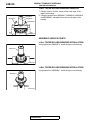
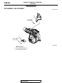
1
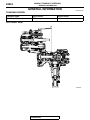
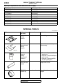
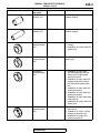
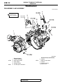
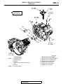
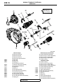
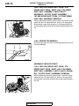
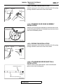
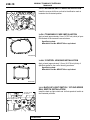
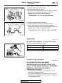
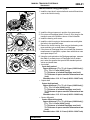
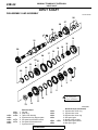
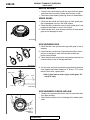
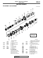
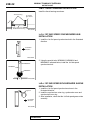
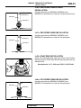
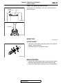
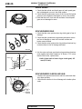
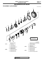
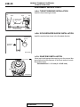
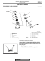
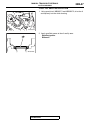
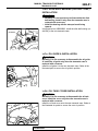
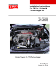
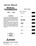
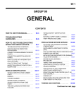
22B-1
GROUP 22B
MANUAL
TRANSAXLE
OVERHAUL
CONTENTS
GENERAL INFORMATION . . . . . . . .
22B-2
GENERAL SPECIFICATIONS . . . . . .
22B-3
SERVICE SPECIFICATIONS. . . . . . .
22B-3
FASTENER TIGHTENING
SPECIFICATIONS . . . . . . . . . . . . . . .
22B-4
SEALANTS AND ADHESIVES . . . . .
22B-4
LUBRICANTS . . . . . . . . . . . . . . . . . .
22B-5
DISASSEMBLY AND ASSEMBLY . . . . . . .
22B-29
INSPECTION. . . . . . . . . . . . . . . . . . . . . . . .
22B-35
REVERSE IDLER GEAR . . . . . . . . . . 22B-37
DISASSEMBLY AND ASSEMBLY . . . . . . .
22B-37
INSPECTION. . . . . . . . . . . . . . . . . . . . . . . .
22B-39
CONTROL HOUSING . . . . . . . . . . . . . 22B-40
DISASSEMBLY AND ASSEMBLY . . . . . . .
22B-6
SPECIAL TOOLS. . . . . . . . . . . . . . . .
22B-8
TRANSAXLE . . . . . . . . . . . . . . . . . . .
22B-12
DISASSEMBLY AND ASSEMBLY . . . . . . .
22B-12
INSPECTION . . . . . . . . . . . . . . . . . . . . . . .
22B-19
TRANSAXLE ADJUSTMENT . . . . . . . . . . .
22B-19
22B-22
DISASSEMBLY AND ASSEMBLY . . . . . . .
22B-22
INSPECTION . . . . . . . . . . . . . . . . . . . . . . .
22B-27
22B-40
SELECT LEVER . . . . . . . . . . . . . . . . . 22B-43
DISASSEMBLY AND ASSEMBLY . . . . . . .
ADJUSTMENT SNAP RING AND
SPACERS . . . . . . . . . . . . . . . . . . . . .
INPUT SHAFT . . . . . . . . . . . . . . . . . .
OUTPUT SHAFT. . . . . . . . . . . . . . . . . 22B-29
22B-43
CLUTCH HOUSING . . . . . . . . . . . . . . 22B-44
DISASSEMBLY AND ASSEMBLY . . . . . . .
22B-44
TRANSAXLE CASE . . . . . . . . . . . . . . 22B-48
DISASSEMBLY AND ASSEMBLY . . . . . . .
22B-48
CENTER DIFFERENTIAL. . . . . . . . . . 22B-53
DISASSEMBLY AND ASSEMBLY . . . . . . .
22B-53
TRANSFER . . . . . . . . . . . . . . . . . . . . . 22B-56
DISASSEMBLY AND ASSEMBLY . . . . . . .
22B-56
22B-2
MANUAL TRANSAXLE OVERHAUL
GENERAL INFORMATION
GENERAL INFORMATION
M1222000100874
TRANSAXLE MODEL
Transaxle model
Engine model
Vehicle model
W5M6A-1-A1ZA
4B11
CZ4A
SECTIONAL VIEW
AK703412
TSB Revision
22B-3
MANUAL TRANSAXLE OVERHAUL
GENERAL SPECIFICATIONS
GENERAL SPECIFICATIONS
M1222000201056
GEAR RATIO TABLE
Item
Specification
Transaxle model
W5M6A
Transaxle type
5-speed
Transaxle gear ratio
1st
2.857
2nd
1.950
3rd
1.444
4th
1.096
5th
0.761
Reverse
2.892
Final reduction ratio
4.687
SERVICE SPECIFICATIONS
Item
M1222000300685
Standard value
Limit
139 −141 (5.48 −5.55)
−
Transaxle
Distance between the control shaft (in neural) and shift
cable bracket mm (in)
Distance between the select lever (3rd-4th speed position) 139.2 −140.8 (5.481 −5.543)
and shift cable bracket mm (in)
−
Input shaft preload mm (in)
0.10 −0.17 (0.0039 −0.0067)
−
Output shaft preload mm (in)
0.15 −0.21 (0.0059 −0.0083)
−
Center differential preload mm (in)
0.06 −0.12 (0.0024 −0.0047)
−
Input shaft taper roller bearing end play mm (in)
0.01 −0.09 (0.0004 −0.0035)
−
Synchronizer inner ring rear end to outer ring rear end
clearance mm (in)
−
0.5 (0.02)
Output shaft 3rd speed gear end play mm (in)
0.01 −0.09 (0.0004 −0.0035)
−
Output shaft taper roller bearing end play mm (in)
0.01 −0.09 (0.0004 −0.0035)
−
Synchronizer inner ring rear end to outer ring rear end
clearance mm (in)
−
0.5 (0.02)
Reverse idler gear thrust washer end play mm (in)
0 −0.11 (0 −0.0043)
−
Synchronizer ring back surface to gear clearance mm (in)
−
0.5 (0.02)
Input shaft
Output shaft
Reverse idler gear
TSB Revision
22B-4
MANUAL TRANSAXLE OVERHAUL
FASTENER TIGHTENING SPECIFICATIONS
FASTENER TIGHTENING SPECIFICATIONS
M1222013900342
TRANSAXLE
Item
Specification
Reverse shift lever
24 ± 4 N⋅ m (17 ± 2 ft-lb)
Clutch housing-transaxle case mounting bolt
50 ± 5 N⋅ m (37 ± 3 ft-lb)
Reverse idler gear shaft mounting bolt
78 ± 7 N⋅ m (57 ± 4 ft-lb)
Poppet spring
32 ± 2 N⋅ m (24 ± 1 ft-ld)
Control housing mounting bolt
24 ± 4 N⋅ m (17 ± 2 ft-lb)
Select lever
24 ± 4 N⋅ m (17 ± 2 ft-lb)
Harness bracket
24 ± 4 N⋅ m (17 ± 2 ft-lb)
Back-up light switch
32 ± 2 N⋅ m (24 ± 1 ft-ld)
1st-2nd speed rail switch
32 ± 2 N⋅ m (24 ± 1 ft-ld)
Hanger bracket
24 ± 4 N⋅ m (17 ± 2 ft-lb)
Stud adapter
50 ± 5 N⋅ m (37 ± 3 ft-lb)
Shift cable bracket
24 ± 4 N⋅ m (17 ± 2 ft-lb)
Transaxle-transfer mounting bolt
69 ± 9 N⋅ m (51 ± 6 ft-lb)
Stopper bracket mounting bolt
19 ± 3 N⋅ m (14 ± 2 ft-lb)
Select lever-select lever bracket connecting nut
11 ± 2 N⋅ m (97 ± 17 in-lb)
Clutch release bearing retainer mounting bolt
10 ± 2 N⋅ m (88 ± 17 in-lb)
Oil guide B
10 ± 2 N⋅ m (88 ± 17 in-lb)
Center differential drive gear mounting bolt
133 ± 4 N⋅ m (98 ± 2 ft-lb)
TRANSFER
Item
Specification
Transfer heat protector
10 ± 2 N⋅ m (88 ± 17 in-lb)
Drive shaft heat protector
9.0 ± 1.0 N⋅ m (79 ± 8 in-lb)
SEALANTS AND ADHESIVES
M1222000500720
Item
Specified sealant
Mating face for transaxle case and clutch housing
Mitsubishi Part No. MD997740 or equivalent
Mating face for transaxle case and control housing
Steel ball
3M™STUD Locking No.4710 or equivalent
Center differential drive gear bolt
Air breather bracket
Three bond 1501 or equivalent
.
TSB Revision
MANUAL TRANSAXLE OVERHAUL
LUBRICANTS
22B-5
FORM-IN-PLACE GASKET (FIPG)
Disassembly
This transaxle has several areas where the
form-in-place gasket (FIPG) is used for sealing. To
ensure that the FIPG fully serves its purpose, it is
necessary to observe some precautions when applying it. Bead size, continuity and location are of paramount importance.
Too thin a bead could cause leaks. Too thick a bead,
on the other hand, could be squeezed out of location,
causing blocking or narrowing of fluid passages. To
prevent leaks or blocking of passages, therefore, it is
absolutely necessary to apply the FIPG evenly without a break, while observing the correct bead size.
FIPG hardens as it reacts with the moisture in the
atmospheric air, and it is usually used for sealing
metallic flange areas.
Parts sealed with a FIPG can be easily removed
without need for the use of a special method. In
some cases, however, the FIPG in joints may have to
be broken by tapping parts with a mallet or similar
tool.
CAUTION
When re-applying liquid gasket (FIPG), be sure
that:
1. Residues of FIPG are cleared from all the ins
and outs of parts;
2. Surfaces to be coated with FIPG are wiped
clean carefully with a quick-drying degreaser
like isopropyl alcohol.
3. FIPG is correctly applied in accordance with
FIPG Application.
.
.
Surface Preparation
Thoroughly remove all substances deposited on the
FIPG application surface, using a gasket scraper.
Make sure that the FIPG application surfaces is flat
and smooth. Also make sure that the surface is free
from oils, greases and foreign substances. Do not fail
to remove old FIPG that may remain in the fastener
fitting holes.
.
FIPG Application
Applied FIPG bead should be of the specified size
and free of any break. FIPG can be wiped away
unless it has completely hardened. Install the mating
parts in position while the FIPG is still wet (in less
than 10 minutes after application). Do not allow FIPG
to spread beyond the sealing areas during installation. Avoid operating the transaxle or letting oils or
water come in contact with the sealed area before a
time sufficient for FIPG to harden (approximately one
hour) has passed.
FIPG application method may vary from location to
location. Follow the instruction for each particular
case described later in this manual.
LUBRICANTS
M1222000400660
Item
Specified sealant
Transaxle oil
Mitsubishi Genuine DiaQueen NEW MULTI GEAR
OIL API classification GL-3, SAE 75W-80
Control shaft oil seal lip gear oil
Oil seal (transaxle case)
Select lever shoe
Mitsubishi Part No. 0101011 or equivalent
Input shaft oil seal lip gear oil
Retinax A
TSB Revision
22B-6
MANUAL TRANSAXLE OVERHAUL
ADJUSTMENT SNAP RING AND SPACERS
ADJUSTMENT SNAP RING AND SPACERS
Snap ring (For adjustment of input shaft rear bearing end play)
Thickness mm (in)
Thickness mm (in)
1.23 (0.0484)
1.55 (0.0610)
1.27 (0.0500)
1.59 (0.0626)
1.31 (0.0516)
1.63 (0.0642)
1.35 (0.0531)
1.67 (0.0657)
1.39 (0.0547)
1.71 (0.0673)
1.43 (0.0563)
1.75 (0.0689)
1.47 (0.0579)
1.79 (0.0705)
1.51 (0.0594)
Spacer (For adjustment of input shaft end play)
Thickness mm (in)
Thickness mm (in)
0.80 (0.0315)
1.16 (0.0457)
0.83 (0.0327)
1.19 (0.0469)
0.86 (0.0339)
1.22 (0.0480)
0.89 (0.0350)
1.25 (0.0492)
0.92 (0.0362)
1.28 (0.0504)
0.95 (0.0374)
1.31 (0.0516)
0.98 (0.0386)
1.34 (0.0528)
1.01 (0.0398)
1.37 (0.0539)
1.04 (0.0409)
1.40 (0.0551)
1.07 (0.0421)
1.43 (0.0563)
1.10 (0.0433)
1.46 (0.0575)
1.13 (0.0445)
1.49 (0.0587)
Snap ring (For adjustment of output shaft 3rd speed gear end play)
Thickness mm (in)
Thickness mm (in)
2.23 (0.0878)
2.47 (0.0972)
2.27 (0.0894)
2.51 (0.0988)
2.31 (0.0909)
2.55 (0.1004)
2.35 (0.0925)
2.59 (0.1020)
2.39 (0.0941)
2.63 (0.1035)
2.43 (0.0957)
2.67 (0.1051)
TSB Revision
M1222012000799
MANUAL TRANSAXLE OVERHAUL
ADJUSTMENT SNAP RING AND SPACERS
Snap ring (For adjustment of output shaft rear bearing end play)
Thickness mm (in)
Thickness mm (in)
1.31 (0.0561)
1.55 (0.0610)
1.35 (0.0531)
1.59 (0.0626)
1.39 (0.0547)
1.63 (0.0642)
1.43 (0.0563)
1.67 (0.0657)
1.47 (0.0579)
1.71 (0.0673)
1.51 (0.0594)
Spacer (For adjustment of output shaft end play)
Thickness mm (in)
Thickness mm (in)
0.86 (0.0339)
1.19 (0.0469)
0.89 (0.0350)
1.22 (0.0480)
0.92 (0.0362)
1.25 (0.0492)
0.95 (0.0374)
1.28 (0.0504)
0.98 (0.0386)
1.31 (0.0516)
1.01 (0.0398)
1.34 (0.0528)
1.04 (0.0409)
1.37 (0.0539)
1.07 (0.0421)
1.40 (0.0551)
1.10 (0.0433)
1.43 (0.0563)
1.13 (0.0445)
1.46 (0.0575)
1.16 (0.0457)
1.49 (0.0587)
Snap ring (For adjustment of reverse idler gear thrust washer end play)
Thickness mm (in)
Thickness mm (in)
1.77 (0.0697)
2.12 (0.0835)
1.82 (0.0717)
2.17 (0.0854)
1.87 (0.0736)
2.22 (0.0874)
1.92 (0.0756)
2.27 (0.0894)
1.97 (0.0776)
2.32 (0.0913)
2.02 (0.0795)
2.37 (0.0933)
2.07 (0.0815)
2.42 (0.0953)
TSB Revision
22B-7
22B-8
MANUAL TRANSAXLE OVERHAUL
SPECIAL TOOLS
Spacer (For adjustment of center differential case end play)
Thickness mm (in)
Thickness mm (in)
1.07 (0.0421)
1.34 (0.0528)
1.10 (0.0433)
1.37 (0.0539)
1.13 (0.0445)
1.40 (0.0551)
1.16 (0.0457)
1.43 (0.0563)
1.19 (0.0469)
1.46 (0.0575)
1.22 (0.0480)
1.49 (0.0587)
1.25 (0.0492)
1.52 (0.0598)
1.28 (0.0504)
1.55 (0.0610)
1.31 (0.0516)
SPECIAL TOOLS
Tool
M1222000600750
Tool number
and name
Supersession
Application
MD998917
Bearing
remover
General service tool
Removal of gears and bearings
MB990560
Rear axle shaft
bearing
remover
−
Removal of output shaft taper
roller bearing
MB990842
Drag link
bushing
remover and
installer B
−
• Removal of input shaft 5th
speed gear
• Removal of output shaft taper
roller bearing
• Removal of output shaft 5th
and 4th speed gears
MB990560
MD999601
−
Valve stem seal
installer
Installation of input shaft and
output shaft oil seal
MD998812
Installer cap
Use with installer and installer
adapter
TSB Revision
General service tool
22B-9
MANUAL TRANSAXLE OVERHAUL
SPECIAL TOOLS
Tool
Tool number
and name
Supersession
Application
MD998813
Installer-100
General service tool
Use with installer cap and
installer adapter
MD998814
Installer-200
MIT304180
Use with installer cap and
installer adapter
MD998819
General service tool
Installer adapter
(40)
• Installation of taper roller
bearing
• Installation of output shaft 5th
speed gear
MD998821
MD998821
Installer adapter
(44)
Installation of output shaft 4th
speed gear
MD998822
−
Installer adapter
(46)
• Installation of input shaft
3rd-4th speed synchronizer
sleeve and 3rd-4th speed
synchronizer hub
• Installation of input shaft 5th
speed synchronizer sleeve
and 5th speed synchronizer
hub
• Installation of input shaft 4th
speed gear sleeve
• Installation of input shaft 5th
speed gear sleeve
• Installation of input shaft taper
roller bearing
• Installation of output shaft 3rd
speed gear
MD998824
General service tool
Installer adapter
(50)
• Installation of output shaft 1st
gear sleeve
• Installation of output 1st-2nd
speed synchronizer hub
• Installation of output 2nd
speed gear sleeve
TSB Revision
22B-10
MANUAL TRANSAXLE OVERHAUL
SPECIAL TOOLS
Tool
Tool number
and name
Supersession
Application
MD998830
−
Installer adapter
(66)
Removal of center differential
taper roller bearing
MD999566
Claw
Removal of control housing oil
seal
General service tool
MB990947
MB990947-01 or
Lower arm push general service tool
arbor
Removal of control housing slide
ball bearing
MB990984
Mount bushing
remover and
installer arbor
−
Installation of control housing
slide ball bearing
MB991246
Lower arm
bushing arbor
−
Installation of control housing oil
seal
MB991946
Pry bar
−
Removal of oil guide
MB990883
Rear
suspension
bushing arbor
MB990883-01 or
general service tool
• Removal of slide ball bearing
• Installation of slide ball bearing
MB990947
MB990883
MD999547
−
Oil seal installer
TSB Revision
• Installation of oil guide
• Installation of center
differential taper roller bearing
22B-11
MANUAL TRANSAXLE OVERHAUL
SPECIAL TOOLS
Tool
MB990847
Tool number
and name
Supersession
Application
MB992075
Handle
−
Installation of oil seal
MB992271
−
Oil seal installer
Installation of oil seal
MB991115
MB991015-01
Oil seal installer
Installation of center differential
oil seal
MB990938
Installer bar
Installation of center differential
oil seal
MB990938-01
MB992272
−
Bearing installer
Installation of center differential
taper roller bearing
MB990847
Rear
suspension
bushing
remover and
installer base
Installation of center differential
taper roller bearing
TSB Revision
MB990847
22B-12
MANUAL TRANSAXLE OVERHAUL
TRANSAXLE
TRANSAXLE
DISASSEMBLY AND ASSEMBLY
Apply gear oil to
all moving parts
before installation.
M1222016500042
50 ± 5 N·m
37 ± 3 ft-lb
3
2
24 ± 4 N·m
17 ± 2 ft-lb
24 ± 4 N·m
17 ± 2 ft-lb
32 ± 2 N·m
24 ± 1 ft-lb
10
4
5
6
7
8
24 ± 4 N·m
17 ± 2 ft-lb
1
9
69 ± 9 N·m
51 ± 6 ft-lb
AK703151AC
>>J<<
>>I<<
1.
2.
3.
4.
5.
Removal steps
Transfer assembly
Shift cable bracket
Stud adapter
Hanger bracket
1st-2nd speed rail switch
TSB Revision
>>I<<
Removal steps (Continued)
6. Gasket
7. Back-up light switch
8. Gasket
9. Harness bracket
10. Select lever
22B-13
MANUAL TRANSAXLE OVERHAUL
TRANSAXLE
24 ± 4 N·m
17 ± 2 ft-lb
11
Apply gear oil to
all moving parts
before installation.
32 ± 2 N·m
24 ± 1 ft-lb
12
50 ± 5 N·m
37 ± 3 ft-lb
13
16
18
17
20
19
22
21
14
15
78 ± 7 N·m
57 ± 4 ft-lb
50 ± 5 N·m
37 ± 3 ft-lb
AK703162AC
>>H<<
>>G<<
Removal steps
11. Control housing
12. Poppet spring
13. Gasket
14. Reverse idler gear shaft mounting
bolt
15. Gasket
16. Transaxle case
TSB Revision
Removal steps (Continued)
17. Outer race (for center differential)
18. Spacer (for center differential)
19. Outer race (for output shaft)
20. Spacer (for output shaft)
21. Outer race (for input shaft)
22. Spacer (for input shaft)
22B-14
MANUAL TRANSAXLE OVERHAUL
TRANSAXLE
Apply gear oil to
all moving parts
before installation.
40
42
41
39
43
38
30
29
2
28
44
32
33
34
24 ± 4 N·m
17 ± 2 ft-lb
35
26
36
23
27
37
46
24
31
45
25
AK703164 AC
<<A>>
<<A>>
<<B>>
<<C>>
<<D>>
<<D>>
<<D>>
<<D>>
<<D>>
<<D>>
<<D>>
<<D>>
<<E>>
Removal steps
23. Reverse shift lever
24. Reverse shift rail
25. Reverse shift fork
26. 5th-reverse speed shift rail
27. Steel ball
28. Steel ball
29. Spring pin
30. 3rd-4th speed shift rail
31. Reverse idler gear assembly
32. 3rd-4th speed shift fork
33. Snap ring
34. Shift lug
35. 5th speed shift fork
36. 5th speed shift rail assembly
37. Input shaft assembly
38. Output shaft assembly
39. 1st-2nd speed shift fork
40. 1st-2nd speed shift rail assembly
41. Spring pin
TSB Revision
>>A<<
>>A<<
>>A<<
>>A<<
>>A<<
>>A<<
Removal steps (Continued)
42. Center differential assembly
43. Outer race (for center differential)
44. Outer race (for output shaft)
45. Outer race (for input shaft)
46. Clutch housing
Installation steps
46. Clutch housing
45. Outer race (for input shaft)
44. Outer race (for output shaft)
43. Outer race (for center differential)
42. Center differential assembly
38. Output shaft assembly
37. Input shaft assembly
36. 5th speed shift rail assembly
35. 5th speed shift fork
34. Shift lug
33. Snap ring
32. 3rd-4th speed shift fork
39. 1st-2nd speed shift fork
40. 1st-2nd speed shift rail assembly
MANUAL TRANSAXLE OVERHAUL
TRANSAXLE
>>B<<
>>C<<
>>D<<
>>E<<
>>F<<
22B-15
Installation steps (Continued)
41. Spring pin
31. Reverse idler gear assembly
30. 3rd-4th speed shift rail
29. Spring pin
28. Steel ball
27. Steel ball
26. 5th-reverse speed shift rail
25. Reverse shift fork
24. Reverse shift rail
23. Reverse shift lever
DISASSEMBLY SERVICE POINTS
.
<<A>> STEEL BALL REMOVAL
Remove the steel balls at the illustrated positions from the shift
lug and 5th speed shift fork.
AK703320AC
.
<<B>> SPRING PIN REMOVAL
Knock the spring pin out of the 3rd-4th speed shift fork from the
illustrated direction.
AK703321
.
<<C>> REVERSE IDLER GEAR ASSEMBLY
REMOVAL
Pull up the input shaft and output shaft together, and remove
the reverse idler gear assembly.
AK703322
.
TSB Revision
22B-16
MANUAL TRANSAXLE OVERHAUL
TRANSAXLE
<<D>> 3RD-4TH SPEED SHIFT FORK / 5TH
SPEED SHIFT FORK / SHIFT LUG / 5TH SPEED
SHIFT RALL ASSEMBLY / INPUT SHAFT
ASSEMBLY / OUTPUT SHAFT ASSEMBLY /
1ST-2ND SPEED SHIFT FORK / 1ST-2ND SPEED
SHIFT RAIL ASSEMBLY REMOVAL
With the differential assembly raised a little, remove the 3rd-4th
speed shift fork, 5th speed shift fork, shift lug, 5th speed shift
rail assembly, output shaft assembly, 1st-2nd speed shift fork,
1st-2nd speed shift rail assembly and input shaft assembly as a
set.
AK703804
.
<<E>> SPRING PIN REMOVAL
Knock the spring pin out of the 1st-2nd speed shift fork from the
illustrated direction.
AK703324
ASSEMBLY SERVICE POINTS
.
>>A<< 3RD-4TH SPEED SHIFT FORK / 5TH
SPEED SHIFT FORK / SHIFT LUG / 5TH SPEED
SHIFT RALL ASSEMBLY / INPUT SHAFT ASSEMBLY / OUTPUT SHAFT ASSEMBLY REMOVAL
With the differential assembly raised a little, install the 3rd-4th
speed shift fork, 5th speed shift fork, shift lug, 5th speed shift
rail assembly, input shaft assembly and output shaft assembly
as a set.
.
AK703323
TSB Revision
MANUAL TRANSAXLE OVERHAUL
TRANSAXLE
22B-17
>>B<< SPRING PIN INSTALLATION
Shift rail
Install the spring pin to the shift rail so that the slit of the spring
pin aligns with the center axis of the rail as shown.
Shift fork
2.5 mm
(0.0984 inch)
Spring pin
AK703408AC
.
>>C<< REVERSE IDLER GEAR ASSEMBLY
INSTALLATION
Install the reverse idler gear assembly so that the notch of the
reverse idler gear shaft and 1st-2nd speed synchronizer sleeve
meet at the illustrated position.
1st-2nd speed
synchronizer sleeve
Reverse idler
gear assembly
AK703681AC
.
>>D<< SPRING PIN INSTALLATION
Shift rail
Spring pin
Shift fork
2.5 mm
(0.0984 inch)
Install the spring pin to the shift rail so that the slit of the spring
pin aligns with the center axis of the rail as shown.
AK703409 AC
.
>>E<< 5TH-REVERSE SPEED SHIFT RALL
INSTALLATION
Identification groove
Install the 5th-reverse speed shift rail, with its identification
groove to the clutch housing side.
Installation
direction
5th-reverse speed shift rail
AK703410AC
.
TSB Revision
22B-18
MANUAL TRANSAXLE OVERHAUL
TRANSAXLE
>>F<< REVERSE SHIFT LEVER INSTALLATION
Addition mark
Install the reverse shift lever so that its identification mark is
located at the illustrated position.
AK703326 AC
.
>>G<< TRANSAXLE CASE INSTALLATION
Apply a bead (approximately 2 mm (0.0787 inch) thick) of specified sealant to the transaxle case as shown.
Specified sealant:
Mitsubishi Part No. MD997740 or equivalent
AK703818AD
.
>>H<< CONTROL HOUSING INSTALLATION
Apply a bead (approximately 3.5 mm (0.1378 inch) thick) of
specified sealant to the control housing as shown.
Specified sealant:
Mitsubishi Part No. MD997740 or equivalent
AK703819AC
.
>>I<< BACK-UP LIGHT SWITCH / 1ST-2ND SPEED
RAIL SWITCH INSTALLATION
1st-2nd speed
rail switch
Install the back-up light switch and 1st-2nd speed rail switch at
the illustrated positions.
Back-up light switch
Control shaft
AK703332AC
.
TSB Revision
22B-19
MANUAL TRANSAXLE OVERHAUL
TRANSAXLE
>>J<< SHIFT CABLE BRACKET INSTALLATION
Control
shaft
Shift cable
139 - 141 mm
bracket
(5.4724 - 5.5512 inch)
1. Install the shift cable bracket loosely.
2. Put the control shaft into neutral.
3. Position the shift cable bracket so that the distance between
the control shaft and shift cable bracket is within the
standard value. Then fix the bracket securely.
Standard value: 139 −141 mm (5.48 −5.55 inch)
AK703153AC
Select lever
139.2 - 1
40.8 mm Shift cable
(5.4803
bracket
- 5.433 in
ch)
Select lever bracket
4. Install the select lever bracket loosely.
5. Put the select lever into the 3rd-4th speed position.
6. Position the select lever bracket so that the distance
between the select lever and shift cable bracket is within the
standard value. Then fix the bracket securely.
Standard value: 139.2 −140.8 mm (5.481 −5.543 inch)
AK703154AC
INSPECTION
M1222016600049
.
BACKUP LIGHT SWITCH / 1-2 speed rall switch
Check for continuity between terminals.
Switch Condition
Continuity
Pressed
Open
Released
Conductive
AK201630
TRANSAXLE ADJUSTMENT
M1222013800129
ADJUSTMENT BEFORE ASSEMBLY
.
SPACER SELECTION FOR INPUT SHAFT PRELOAD / OUTPUT SHAFT PRELOAD / CENTER DIFFERENTIAL PRELOAD ADJUSTMENT
<Measurement using solder>
• If soft solder is not available, select the spacer in accordance with Plastigage method.
• If the spacer appropriate for the standard value cannot be
selected using soft solder, select the spacer in accordance
with Plastigage method.
TSB Revision
22B-20
MANUAL TRANSAXLE OVERHAUL
TRANSAXLE
1. Install the input shaft, output shaft and center differential as
a set to the clutch housing.
AK703323
Solders
AK703327AC
Solders
Solders
AK703329AC
2. Put a piece of solder [1.6 mm (0.06 in) diameter, 10 mm
(0.39 in) long] on the transaxle case at the positions shown
in the illustration.
3. Install the bearing outer races on the pieces of solder.
4. Install the clutch housing to the transaxle case and tighten
the bolts to the specified torque.
5. Remove the clutch housing, then remove the bearing outer
races and take out crushed pieces of solder.
NOTE: If the pieces of solder have not crushed, use thicker
solders and repeat steps 2 to 3.
6. Measure the thickness of crushed solder with a micrometer,
select the spacers that provide the standard preload values
and install them.
• Input shaft
Input shaft preload
Spacer thickness: [T + 0.10 mm (0.0039 inch)] −[T +
0.17 mm (0.0067 inch)]
T: Thickness of crushed solder mm (inch)
Standard value: 0.10 −0.17 mm (0.0039 −0.0067 inch)
• Output shaft
Output shaft preload
Spacer thickness: [T + 0.15 mm (0.0059 inch)] −[T +
0.21 mm (0.0083 inch)]
T: Thickness of crushed solder mm (inch)
Standard value: 0.15 −0.21 mm (0.0059 −0.0083 inch)
• Center differential
Center differential preload
Spacer thickness: [T + 0.06 (0.0024 inch)] −[T + 0.12
mm (0.0047 inch)]
T: Thickness of crushed solder mm (inch)
Standard value: 0.06 −0.12 mm (0.0024 −0.0047 inch)
.
TSB Revision
MANUAL TRANSAXLE OVERHAUL
TRANSAXLE
22B-21
<Measurement using plastigage>
1. Install the input shaft, output shaft and center differential as
a set to the clutch housing.
AK703323
Plastigage
AK703327AD
Plastigage
Plastigage
AK703329AD
2. Install the thinnest spacers in position for measurement.
3. Put a piece of Plastigage [about 10 mm (0.39 in) long] on the
transaxle case at the positions shown in the illustration.
4. Install the bearing outer races.
5. Install the clutch housing to the transaxle case and tighten
the bolts to the specified torque.
6. Remove the clutch housing, then remove the bearing outer
races and take out crushed pieces of Plastigage.
7. If the pieces of Plastigage have not crushed and clearance
measurement is impossible, replace them with thicker ones
and repeat steps 3 to 5.
8. Using the scale printed on the Plastigage package, measure
the width of crushed pieces of Plastigage at their widest
part, select the spacers that provide the standard preload
values and install them.
• Input shaft
Input shaft preload
Spacer thickness: [T1 + T2 + 0.10 mm (0.0039 inch)] −
[T1 + T2 + 0.17 mm (0.0067 inch)]
T1: Thickness of crushed Plastigage mm (inch)
T2: Thickness of spacer used for measurement mm
(inch)
Standard value: 0.10 −0.17 mm (0.0039 −0.0067 inch)
• Output shaft
Output shaft preload
Spacer thickness: [T1 + T2 + 0.15 mm (0.0059 inch)] −
[T1 + T2 + 0.21 mm (0.0083 inch)]
T1: Thickness of crushed Plastigage mm (inch)
T2: Thickness of spacer used for measurement mm
(inch)
Standard value: 0.15 −0.21 mm (0.0059 −0.0083 inch)
• Center differential
Center differential preload
Spacer thickness: [T1 + T2 + 0.06 mm (0.0024 inch)] −
[T1 + T2 + 0.12 mm (0.0047 inch)]
T1: Thickness of crushed Plastigage mm (inch)
T2: Thickness of spacer used for measurement mm
(inch)
Standard value: 0.06 −0.12 mm (0.0024 −0.0047 inch)
TSB Revision
22B-22
MANUAL TRANSAXLE OVERHAUL
INPUT SHAFT
INPUT SHAFT
DISASSEMBLY AND ASSEMBLY
M1222001600667
26
27
28
29
1
14
31
15
16
19
30
18
17
20
22
21
23
7
24
25
2
3
4
6
5
8
9
Apply gear oil to
all moving parts
before installation.
10
12
11
13
AK702340AD
<<A>>
<<A>>
<<A>>
<<A>>
<<A>>
>>I<<
>>H<<
>>G<<
>>F<<
>>F<<
1.
2.
3.
4.
5.
6.
7.
Removal steps
Oil seal
Snap ring
Taper roller bearing
Synchronizer key stopper plate
5th speed synchronizer sleeve
5th speed synchronizer hub
Synchronizer key
TSB Revision
<<A>>
<<A>>
<<A>>
<<A>>
<<B>>
<<B>>
>>E<<
Removal steps (Continued)
8. Synchronizer outer ring
9. Synchronizer cone
10. Synchronizer inner ring
11. 5th speed gear
12. Needle roller bearing
13. 5th speed gear sleeve
14. 4th speed gear
MANUAL TRANSAXLE OVERHAUL
INPUT SHAFT
<<B>>
<<B>>
<<B>>
<<B>>
<<B>>
<<B>>
<<B>>
<<B>>
<<B>>
<<B>>
<<B>>
<<B>>
<<B>>
<<C>>
>>D<<
>>C<<
>>C<<
>>B<<
>>B<<
>>A<<
22B-23
Removal steps (Continued)
15. Needle roller bearing
16. 4th speed gear sleeve
17. Synchronizer outer ring
18. Synchronizer cone
19. Synchronizer inner ring
20. 3rd-4th speed synchronizer sleeve
21. 3rd-4th speed synchronizer hub
22. Synchronizer key
23. Synchronizer outer ring
24. Synchronizer cone
25. Synchronizer inner ring
26. Thrust bearing
27. 3rd speed gear
28. Needle roller bearing
29. Thrust bearing
30. Taper roller bearing
31. Input shaft
Required Special Tools:
• MD998917: Bearing remover
• MB990842: Drag link bushing remover and
installer B
• MD998812: Installer cap
•
•
•
•
MD998813: Installer-100
MD998819: Installer adapter (40)
MD998822: Installer adapter (46)
MD999601: Valve stem seal installer
DISASSEMBLY SERVICE POINTS
.
<<A>> 5TH SPEED GEAR / SYNCHRONIZER
INNER RING / SYNCHRONIZER CONE / SYNCHRONIZER OUTER RING / 5TH SPEED SYNCHRONIZER HUB / TAPER ROLLER BEARING /
SYNCHRONIZER KEY STOPPER PLATE / 5TH
SPEED SYNCHRONIZER SLEEVE REMOVAL
MB990842
MD998917
Using the special tools, MD998917 and MB990842, indicated
below, remove the 5th speed gear, 5th speed synchronizer
sleeve, 5th speed synchronizer hub, synchronizer inner ring,
synchronizer outer ring, synchronizer cone, synchronizer key
stopper plate and taper roller bearing.
AK703165AC
.
TSB Revision
22B-24
MANUAL TRANSAXLE OVERHAUL
INPUT SHAFT
<<B>> 3RD SPEED GEAR / 5TH SPEED GEAR
SLEEVE / 4TH SPEED GEAR / NEEDLE ROLLER
BEARING / 4TH SPEED GEAR SLEEVE /
SYNCHRONIZER OUTER RING / SYNCHRONIZER
CONE / SYNCHRONIZER INNER RING / 3RD-4TH
SPEED SYNCHRONIZER SLEEVE / 3RD-4TH
SPEED SYNCHRONIZER HUB / THRUST
BEARING / 3RD SPEED GEAR REMOVAL
Using special tool, MD998917, support the 3rd speed gear, and
then remove the 3rd seed gear, thrust bearings, 3rd-4th speed
synchronizer sleeve, 3rd-4th speed synchronizer hub, synchronizer outer ring, synchronizer inner ring, synchronizer cone, 4th
speed gear, needle roller bearing, 4th speed gear sleeve and
5th speed gear sleeve.
MD998917
AK703166AC
.
<<C>> TAPER ROLLER BEARING REMOVAL
Using special tool, MD998917, remove the taper roller bearing.
MD998917
AK703167 AD
ASSEMBLY SERVICE POINTS
.
>>A<< TAPER ROLLER BEARING INSTALLATION
Using the special tools, MD998812, MD998813 and
MD998819, indicated below, install the taper roller bearing.
MD998812
MD998813
MD998819
AK703168AC
.
TSB Revision
MANUAL TRANSAXLE OVERHAUL
INPUT SHAFT
22B-25
>>B<< THRUST BEARING INSTALLATION
Colorless
(thin)
Black
(thick)
3rd speed gear
Colorless
(thin)
Black
(thick)
Install the thrust bearings as shown.
AK703374AC
.
>>C<< 3RD-4TH SPEED SYNCHRONIZER HUB /
3RD-4TH SPEED SYNCHRONIZER SLEEVE
INSTALLATION
1. Install the 3rd-4th speed synchronizer hub and synchronizer
sleeve in the illustrated direction.
Identification groove
Installation
direction
AK703159AC
2. Using the special tools, MD998812, MD998813 and
MD998822, indicated below, install the 3rd-4th speed
synchronizer sleeve, 3rd-4th speed synchronizer hub,
synchronizer outer ring, synchronizer inner ring and
synchronizer cone.
3. After installation, check that the 3rd speed gear rotates
smoothly.
MD998812
MD998813
MD998822
AK703169AC
.
>>D<< 4TH SPEED GEAR SLEEVE
INSTALLATION
Using the special tools, MD998812, MD998813 and
MD998822, indicated below, install the 4th speed gear sleeve.
MD998812
MD998813
MD998822
AK703170AC
.
TSB Revision
22B-26
MANUAL TRANSAXLE OVERHAUL
INPUT SHAFT
>>E<< 5TH SPEED GEAR SLEEVE INSTALLATION
Using the special tools, MD998812, MD998813 and
MD998822, indicated below, install the 5th speed gear sleeve.
MD998812
MD998813
MD998822
AK703171AC
.
>>F<< 5TH SPEED SYNCHRONIZER HUB / 5TH
SYNCHRONIZER SLEEVE INSTALLATION
1. Install the 5th speed synchronizer hub and synchronizer
sleeve in the illustrated direction.
Identification
groove
Installation
direction
Identification
groove
AK703158AC
2. Using the special tools, MD998812, MD998813 and
MD998822, indicated below, install the 5th speed
synchronizer hub and synchronizer sleeve.
3. After installation, check that the 5th speed gear rotates
smoothly.
MD998812
MD998813
MD998822
AK703172AC
.
>>G<< TAPER ROLLER BEARING INSTALLATION
Using the special tools, MD998812, MD998813 and
MD998822, indicated below, press-fit the taper roller bearing.
MD998812
MD998813
MD998822
AK703173AC
.
TSB Revision
MANUAL TRANSAXLE OVERHAUL
INPUT SHAFT
22B-27
>>H<< SNAP RING INSTALLATION
Select and install appropriate snap ring onto the input shaft so
that the clearance of the taper roller bearing meets the standard value.
Standard value: 0.01 −0.09 mm (0.0004 −0.0035 inch)
AK703174
.
>>I<< OIL SEAL INSTALLATION
3.5 mm
(0.1378 inch)
Using special tool, MD999601, drive the oil seal as deep as
shown into place.
Oil seal
AK702519AD
MD999601
AK703175AC
INSPECTION
M1222001700330
.
INPUT SHAFT
• Check the needle bearing mounting portion of the shaft for
damage, wear and seizure.
• Check the splines for damage and wear.
AK702517AC
.
TSB Revision
22B-28
MANUAL TRANSAXLE OVERHAUL
INPUT SHAFT
NEEDLE BEARING
• Combine the needle bearing with the input shaft and gears
and check that it smoothly rotates without noise or play.
• Check the needle bearing retaining sleeve for deformation.
.
SPEED GEARS
1. Check that the helical and clutch gears of each speed gear
are not damaged or worn in the tooth surface.
2. Check that the synchronizer cone of each speed gear is not
roughened, damaged or worn in the surface.
3. Check that the inner, front and rear surfaces of each speed
gear are not damaged or worn.
AK204169AD
.
SYNCHRONIZER RING
1. Check that the outer synchronizer ring clutch gear is free of
damage.
2. Check that the synchronizer rings and synchronizer cones
are free of damage or wear in the contact surface and
broken screw threads.
3. Check that the outer synchronizer ring and synchronizer key
contact surface is free of damage and wear.
AK703376AC
A
Outer ring
Cone
Inner ring
Gear
4. Join the outer and inner synchronizer rings and synchronizer
cone together and check clearance "A" shown. If "A" is less
than the limit value, replace them.
Limit A (from back of outer ring to clutch gear): 0.5
mm (0.02 inch)
AK703161AC
.
SYNCHRONIZER SLEEVE AND HUB
• Combine the synchronizer sleeve and hub, and check that
they slide smoothly.
• Check that the sleeve is free of damage at its inside spline
ends.
AK703375
TSB Revision
22B-29
MANUAL TRANSAXLE OVERHAUL
OUTPUT SHAFT
OUTPUT SHAFT
DISASSEMBLY AND ASSEMBLY
M1222002200598
20
21
22
23
24
25
26
1
3
27
5
2
4
6
8
11
7
9
16
18
14
10
Apply gear oil to
all moving parts
before installation.
13
12
15
19
<<A>>
<<B>>
<<C>>
<<C>>
<<D>>
>>M<<
>>L<<
>>K<<
>>J<<
>>I<<
>>H<<
>>G<<
>>F<<
17
AK702341AC
Removal steps
1. Oil seal
2. Taper roller bearing
3. Snap ring
4. Taper roller bearing
5. Collar
6. 5th speed gear
7. 4th speed gear
8. Snap ring
9. 3rd speed gear
10.2nd speed gear
11. Needle roller bearing
12.Synchronizer outer ring
13.Synchronizer cone
14.Synchronizer inner ring
TSB Revision
>>D<<
<<E>>
<<E>>
>>E<<
>>C<<
<<E>>
<<E>>
<<E>>
<<E>>
<<E>>
<<E>>
<<E>>
<<E>>
<<E>>
>>B<<
>>B<<
>>A<<
Removal steps (Continued)
15.1st-2nd speed synchronizer
sleeve
16.2nd speed gear sleeve
17.1st-2nd speed synchronizer
hub
18.Synchronizer key
19.Synchronizer outer ring
20.Synchronizer cone
21.Synchronizer inner ring
22.Thrust bearing
23.1st speed gear
24.Needle roller bearing
25.Thrust bearing
26.1st speed gear sleeve
27.Output shaft
22B-30
MANUAL TRANSAXLE OVERHAUL
OUTPUT SHAFT
Required Special Tools:
• MB990560: Rear axle shaft bearing remover
• MB990842: Drag link bushing remover and
installer B
• MD998917: Bearing remover
• MD998812: Installer cap
• MD998814: Installer-200
•
•
•
•
•
•
MD998824: Installer adapter (50)
MD998822: Installer adapter (46)
MD998813: Installer-100
MD998821: Installer adapter (44)
MD998819: Installer adapter (40)
MD999601: Valve stem seal installer
DISASSEMBLY SERVICE POINTS
.
<<A>> TAPER ROLLER BEARING REMOVAL
MB990560
MB990842
1. Using a chisel or the like, knock off the roller cage of the
taper roller bearing.
2. Using the special tools, MB990842 and MB990560,
indicated below, remove the taper roller bearing.
AK703313AC
.
<<B>> TAPER ROLLER BEARING REMOVAL
MD998917
MB990842
Using the special tools, MD998917 and MB990842, indicated
below, remove the taper roller bearing.
AK703177AC
.
<<C>> 5TH SPEED GEAR / 4TH SPEED GEAR
REMOVAL
MB990842
Using the special tools, MD998917 and MB990842, indicated
below, remove the 5th speed gear and 4th speed gear.
MD998917
AK703178AC
.
TSB Revision
MANUAL TRANSAXLE OVERHAUL
OUTPUT SHAFT
22B-31
<<D>> 3RD SPEED GEAR REMOVAL
Using special tool, MD998917, remove the 3rd speed gear.
MD998917
AK703301AC
.
<<E>> NEEDLE ROLLER BEARING /
SYNCHRONIZER CONE / SYNCHRONIZER
OUTER RING / SYNCHRONIZER INNER RING /
THRUST BEARING / 2ND SPEED GEAR SLEEVE /
1ST-2ND SPEED SYNCHRONIZER HUB / 1ST
SPEED GEAR / 1ST SPEED GEAR SLEEVE
REMOVAL
Using special tool, MD998917, support the 1st speed gear
sleeve, and then remove the 2nd speed gear sleeve, 1st-2nd
speed synchronizer hub, synchronizer cones, synchronizer
outer rings, synchronizer inner rings, thrust bearings, 1st speed
gear, needle roller bearing and 1st speed gear sleeve.
MD998917
AK703302AC
ASSEMBLY SERVICE POINTS
.
>>A<< 1ST SPEED GEAR SLEEVE INSTALLATION
MD998812
Using the special tools, MD998812, MD998814 and
MD998824, indicated below, install the 1st speed gear sleeve.
MD998814
MD998824
AK703303AC
.
TSB Revision
22B-32
MANUAL TRANSAXLE OVERHAUL
OUTPUT SHAFT
>>B<< THRUST BEARING INSTALLATION
Install the thrust bearings as shown.
Thrust bearing
1st speed
gear sleeve
Needle roller bearing
AK703377AC
.
>>C<< 1ST-2ND SPEED SYNCHRONIZER HUB
INSTALLATION
1. Install the 1st-2nd speed synchronizer hub in the illustrated
direction.
Installation
direction
AK703378AC
2. Using the special tools, MD998812, MD998814 and
MD998824, indicated below, install the 1st-2nd speed
synchronizer hub.
MD998812
MD998814
MD998824
AK703304AC
.
>>D<< 1ST-2ND SPEED SYNCHRONIZER SLEEVE
INSTALLATION
Identification
groove
Installation
direction
1. Install the 1st-2nd speed synchronizer sleeve in the
illustrated direction.
2. Install the synchronizer outer ring, synchronizer cone and
synchronizer inner ring.
3. After installation, check that the 1st-2nd speed gears rotate
smoothly.
AK703379AC
.
TSB Revision
MANUAL TRANSAXLE OVERHAUL
OUTPUT SHAFT
22B-33
>>E<< 2ND SPEED GEAR SLEEVE
INSTALLATION
MD998812
Using the special tools, MD998812, MD998814 and
MD998824, indicated below, install the 2nd speed gear sleeve.
MD998814
MD998824
AK703305AC
.
>>F<< 3RD SPEED GEAR INSTALLATION
MD998812
Using the special tools, MD998812, MD998814 and
MD998822, indicated below, install the 3rd speed gear.
MD998814
MD998822
AK703306AC
.
>>G<< SNAP RING INSTALLATION
Select and install appropriate snap ring onto the output shaft so
that the clearance of the output shaft-3rd speed gear meets the
standard value.
Standard value: 0.01 −0.09 mm (0.0004 −0.0035 inch)
AK703179
.
>>H<< 4TH SPEED GEAR INSTALLATION
MD998812
Using the special tools, MD998812, MD998813 and
MD998821, indicated below, install the 4th speed gear.
MD998813
MD998821
AK703307AC
.
TSB Revision
22B-34
MANUAL TRANSAXLE OVERHAUL
OUTPUT SHAFT
>>I<< 5TH SPEED GEAR INSTALLATION
MD998812
Using the special tools, MD998812, MD998813 and
MD998819, indicated below, install the 5th speed gear.
MD998813
MD998819
AK703308AC
.
>>J<< TAPER ROLLER BEARING INSTALLATION
MD998812
Using the special tools, MD998812, MD998813 and
MD998819, indicated below, press-fit the taper roller bearing.
MD998813
MD998819
AK703309AC
.
>>K<< SNAP RING INSTALLATION
Snap ring
Select and install appropriate snap ring onto the output shaft so
that the clearance of the taper roller bearing meets the standard value.
Standard value: 0.01 −0.09 mm (0.0004 −0.0035 inch)
AK703380AC
.
>>L<< TAPER ROLLER BEARING INSTALLATION
MD998812
MD998819
Using the special tools, MD998812 and MD998819, indicated
below, install the taper roller bearing.
AK703414AC
.
TSB Revision
MANUAL TRANSAXLE OVERHAUL
OUTPUT SHAFT
22B-35
>>M<< OIL SEAL INSTALLATION
3.5 mm
(0.1378 inch)
Using special tool, MD999601, drive the oil seal as deep as
shown into place.
Oil seal
AK702519AD
MD999601
AK703176AC
INSPECTION
M1222002300294
.
OUTPUT SHAFT
• Check the needle bearing mounting portion of the shaft for
damage, wear and seizure.
• Check the splines for damage and wear.
AK702518AC
.
NEEDLE BEARING
• Combine the needle bearing with the input shaft and gears
and check that it smoothly rotates without noise or play.
• Check the needle bearing retaining sleeve for deformation.
.
TSB Revision
22B-36
MANUAL TRANSAXLE OVERHAUL
OUTPUT SHAFT
SPEED GEARS
1. Check that the helical and clutch gears of each speed gear
are not damaged or worn in the tooth surface.
2. Check that the synchronizer cones of the 1st and 2nd speed
gears are not roughened, damaged or worn in the surface.
3. heck that the inner, front and rear surfaces of each speed
gear are not damaged or worn.
AK204169AD
.
SYNCHRONIZER RING
1. Check that the outer synchronizer ring clutch gear is free of
damage.
2. Check that the synchronizer rings and synchronizer cones
are free of damage or wear in the contact surface and
broken screw threads.
3. Check that the outer synchronizer ring and synchronizer key
contact surface is free of damage and wear.
AK703376AC
A
Gear
Outer ring
Cone
Inner ring
4. Join the outer and inner synchronizer rings and synchronizer
cone together and check clearance "A" shown. If "A" is less
than the limit value, replace them.
Limit A (from back of outer ring to clutch gear): 0.5
mm (0.02 inch)
AK703160AC
.
SYNCHRONIZER SLEEVE AND HUB
• Combine the synchronizer sleeve and hub, and check that
they slide smoothly.
• Check that the sleeve is free of damage at its inside spline
ends.
AK703375
TSB Revision
22B-37
MANUAL TRANSAXLE OVERHAUL
REVERSE IDLER GEAR
REVERSE IDLER GEAR
DISASSEMBLY AND ASSEMBLY
M1222012500299
7
9
8
10
6
5
4
3
2
1
18
17
12
14
16
Apply gear oil to
all moving parts
before installation.
15
11
>>C<<
>>B<<
1.
2.
3.
4.
5.
6.
7.
8.
9.
13
AK702513AC
Removal steps
Snap ring
Thrust washer A
Thrust bearing
Reverse idler gear A
Needle bearing
Needle bearing
Synchronizer sleeve
Synchronizer ring
Synchronizer key
TSB Revision
>>A<<
>>A<<
10.
11.
12.
13.
14.
15.
16.
17.
18.
Removal steps (Continued)
Thrust bearing
Thrust washer B
Steel ball
Thrust bearing
Reverse idler gear B
Needle bearing
Needle bearing
Thrust bearing
Reverse idler gear shaft
22B-38
MANUAL TRANSAXLE OVERHAUL
REVERSE IDLER GEAR
DISASSEMBLY SERVICE POINTS
.
>>A<< THRUST BEARING INSTALLATION
Install the thrust bearing as shown.
Thin
Thich
Thich
Thin
Reverse idler
gear shaft
Thrust bearing
AK703381AC
.
>>B<< SYNCHRONIZER SLEEVE INSTALLATION
Install the synchronizer sleeve in the illustrated direction.
Identification
groove
Installation
direction
AK703156AC
.
>>C<< SNAP RING INSTALLATION
Thrust washer
.Select and install appropriate snap ring onto the reverse idler
gear shaft so that the clearance of the thrust washer A meets
the standard value.
Standard Value: 0 −0.11 mm (0 −0.0043 inch)
Snap ring
AK703318AC
TSB Revision
MANUAL TRANSAXLE OVERHAUL
REVERSE IDLER GEAR
INSPECTION
22B-39
M1222012400117
.
REVERSE IDLER GEAR
AK204103AD
1. Check that the synchronizer ring clutch gear teeth are free of
damage.
2. Check that the inside surface of the synchronizer ring cone
is free of damage and wear.
3. Check that the synchronizer ring and synchronizer key are
not damaged or worn in the contact surface.
4. Press the synchronizer ring against the gear and check
clearance "A". If "A" is less than the limit value, replace the
synchronizer ring.
Limit: 0.5 mm (0.02 inch)
.
NEEDLE BEARING
1. Assemble the needle bearing with the reverse idler shaft
and gear, and check that the bearing rotates smoothly
without noise or play.
2. Check that needle bearing retaining sleeve for deformation.
.
REVERSE IDLER GEAR
Reverse idler gear A
1. Check that the helical gear and the tooth surfaces of the
clutch gear of the reverse idler gear A are free of damage or
wear.
2. Check that the synchronizer ring of the reverse idler gear A
is not roughened, damaged or worn in the surface.
3. Check that the helical gear of the reverse idler gear is free of
damage or wear.
AK703383AC
TSB Revision
22B-40
MANUAL TRANSAXLE OVERHAUL
CONTROL HOUSING
CONTROL HOUSING
DISASSEMBLY AND ASSEMBLY
M1222013100391
12
13
4
14
11
15
10
16
9
3
8
2
19 ± 3 N·m
14 ± 2 ft-lb
1
7
5
6
AK702514AC
<<A>>
>>D<<
>>C<<
1.
2.
3.
4.
5.
6.
7.
8.
Removal steps
Stopper bracket mounting bolt
Spring washer
Stopper bracket
Lock pin
Snap ring
Return spring holder B
Return spring
Return spring holder A
Required Special Tools:
• MD999566: Claw
• MB990947: Lower arm bushing arbor
TSB Revision
<<B>>
<<C>>
>>B<<
>>A<<
Removal steps (Continued)
9. Washer
10.Interlock plate
11. Neutral return spring
12.Control shaft
13.Control shaft boot
14.Oil seal
15.Slide ball bearing
16.Control housing
• MB990984: Mount bushing remover and installer
arbor
• MB991246: Lower arm bushing arbor
MANUAL TRANSAXLE OVERHAUL
CONTROL HOUSING
22B-41
DISASSEMBLY SERVICE POINTS
.
<<A>> LOCK PIN REMOVAL
Drive out the lock pin in the direction shown.
AK703310
.
<<B>> OIL SEAL REMOVAL
Using special tool, MD999566, remove the oil seal.
MD999566
AK703311AC
.
<<C>> SLIDE BALL BEARING REMOVAL
Using special tool, MB990947, remove the slide ball bearing.
MB990947
Slide ball bearing
AK703384AC
ASSEMBLY SERVICE POINTS
.
>>A<< SLIDE BALL BEARING INSTALLATION
MB990984
Using special tool, MB990984, install the slide ball bearing in
alignment with the control housing end face taking care not to
let the bearing protrude to the oil seal installing surface.
AK703367AC
TSB Revision
22B-42
MANUAL TRANSAXLE OVERHAUL
CONTROL HOUSING
.
>>B<< OIL SEAL INSTALLATION
1. Using special tool, MB991246, install the oil seal.
2. Apply specified transmission oil to the oil seal lip area.
Specified transaxle oil:
Mitsubishi Genuine DiaQueen New Multi Gear oil SAE
75W-80 (GL-3)
MB991246
AK703312AC
.
>>C<< LOCK PIN INSTALLATION
Drive the lock pin all the way into place to the end face from the
illustrated direction.
AK703310
.
>>D<< STOPPER BRACKET INSTALLATION
Tighten the stopper bracket mounting bolts to the specified
torque in the illustrated order.
1
2
3
AK703385AC
TSB Revision
22B-43
MANUAL TRANSAXLE OVERHAUL
SELECT LEVER
SELECT LEVER
DISASSEMBLY AND ASSEMBLY
M1222012800320
1
11 ± 2 N·m
97 ± 17 in-lb
7
2
3
8
4
5
9
6
10
AK703152 AC
1.
2.
3.
4.
5.
Removal steps
Dust cover
Nut
Spring washer
Washer
Select lever bushing
>>A<<
Removal steps (Continued)
6. Select lever bracket
7. Select lever bushing
8. Dust cover
9. Select lever
10. Select lever shoe
ASSEMBLY SERVICE POINTS
.
>>A<< SELECT LEVER SHOE INSTALLATION
Apply specified grease to the sliding contact surface of the
select lever shoe.
Specified grease:
Mitsubishi Part No. 0101011 or equivalent
Select lever shoe
AK703386AC
TSB Revision
22B-44
MANUAL TRANSAXLE OVERHAUL
CLUTCH HOUSING
CLUTCH HOUSING
DISASSEMBLY AND ASSEMBLY
M1222003700596
7*
5
4
10
6
9*
8*
1
10 ± 2 N·m
88 ± 17 in-lb
2
3
AK702515 AC
>>D<<
<<A>>
>>C<<
>>B<<
1.
2.
3.
4.
5.
6.
7.
Removal steps
Clutch release bearing retainer
Oil seal
Maintenance hole cover
Cover A
Cover B
Output front oil guide
Oil tank cover (CHG)*
Required Special Tools:
• MB991946: Ply bar
• MB990883: Rear suspension bushing arbor
• MD999547: Oil seal installer
TSB Revision
>>B<<
>>A<<
Removal steps (Continued)
8. Oil tank cover (REV)*
9. Slide ball bearing (for shift rail)*
10. Clutch housing
NOTE: *Refer to the assembly service points only
when the clutch housing is replaced.
• MB992271: Oil seal installer
• MB992075: Hamdle
MANUAL TRANSAXLE OVERHAUL
CLUTCH HOUSING
22B-45
DISASSEMBLY SERVICE POINTS
.
<<A>> OUTPUT FRONT OIL GUIDE REMOVAL
Using special tool, MB991946, remove the output front oil
guide.
MB991946
AK703336AC
ASSEMBLY SERVICE POINTS
.
>>A<< SLIDE BALL BEARING (FOR SHIFT RAIL)
INSTALLATION
CAUTION
• Normally, it is not necessary to disassemble the slide
ball bearings. Install them only when the clutch housing is replaced with a new one.
• Install the bearing with the stamped mark facing
upward.
Using special tool, MB990883, install the slide ball bearings on
the new clutch housing.
MB990883
AK703333AC
.
TSB Revision
22B-46
MANUAL TRANSAXLE OVERHAUL
CLUTCH HOUSING
>>B<< OIL TANK COVER (REV) / OIL TANK
COVER (CHG) INSTALLATION
CAUTION
Normally, it is not necessary to disassemble the oil tank
covers. Install them only when the clutch housing is
replaced with a new one.
Install the oil tank covers to the new clutch housing. Stake the
projections at the illustrated positions of the clutch housing to
secure the covers in position.
AK703334AC
AK703335AC
.
>>C<< OUTPUT FRONT OIL GUIDE
INSTALLATION
CAUTION
Make sure that the output front oil guide is installed
squarely.
Using special tool, MD999547, drive the oil guide all the way
into place to the end face of the clutch housing.
MD999547
AK703337AC
.
TSB Revision
MANUAL TRANSAXLE OVERHAUL
CLUTCH HOUSING
22B-47
>>D<< OIL SEAL INSTALLATION
1. Using special tool, MB992271 and MB992075, drive the oil
seal squarely into the clutch housing.
MB992075
MB992271
AK703403AC
2. Apply specified grease to the oil seal lip area.
Specified grease:
Retinax A
AK703411AC
TSB Revision
22B-48
MANUAL TRANSAXLE OVERHAUL
TRANSAXLE CASE
TRANSAXLE CASE
DISASSEMBLY AND ASSEMBLY
M1222016300048
9
6*
7
8
10
3*
5*
A - A
1
2
10 ± 2 N·m
88 ± 17 in-lb
4*
AK702516 AC
<<A>>
>>H<<
>>G<<
>>F<<
>>E<<
>>D<<
>>C<<
Removal steps
Oil guide
Oil tank cover *
Oil guide A*
Oil guide B
Slide ball bearing (for shift
rail)*
6. Slide ball bearing (for control
shaft)*
7. Oil seal
1.
2.
3.
4.
5.
Required Special Tools:
• MB991946: Ply bar
• MB990883: Rear suspension bushing arbor
• MB991115: Oil seal installer
TSB Revision
>>B<<
>>A<<
Removal steps (Continued)
8. Steel ball
9. Air breather
10.Transaxle case
NOTE: *: Refer to the assembly service points only
when the transaxle case is replaced.
• MB990938: Installer bar
• MD999547: Oil seal installer
MANUAL TRANSAXLE OVERHAUL
TRANSAXLE CASE
22B-49
DISASSEMBLY SERVICE POINTS
.
<<A>> OIL GUIDE REMOVAL
MB991946
Using special tool, MB991946, remove the oil guides from the
transaxle case.
AK703404AC
ASSEMBLY SERVICE POINTS
.
>>A<< AIR BREATHER INSTALLATION
Identification mark
Clutch housing
side
1. Apply specified sealant to the periphery of the air breather
insertion part.
Specified sealant:
Three bond 1501 or equivalemt
2. Install the air breather to the transaxle case in accordance
with the illustrated identification mark.
AK703373AC
.
>>B<< STEEL BALL INSTALLATION
Steel ball
1. Apply specified sealant to the periphery of the transaxle
case where the steel ball is installed, then install the steel
ball onto the transaxle case.
Specified sealant:
3M™STUD Locking No.4710 or equivalent
AK703371AC
MB990883
2. Using special tool, MB990883, install the steel ball.
AK703372 AC
.
TSB Revision
22B-50
MANUAL TRANSAXLE OVERHAUL
TRANSAXLE CASE
>>C<< OIL SEAL INSTALLATION
1. Using the special tools, MB991115 and MB990938,
indicated below, install the oil seal to the transaxle case.
MB990938
MB991115
AK703406AC
2. Apply specified transaxle oil to the oil seal lip area.
Specified transaxle oil:
Mitsubishi Genuine DiaQueen New Multi Gear Oil SAE
75W-80 (GL-3)
.
>>D<< SLIDE BALL BEARING (FOR CONTROL
SHAFT) INSTALLATION
AK703405 AC
CAUTION
• Normally, it is not necessary to disassemble the slide
ball bearing. Install it only when the transaxle case is
replaced with a new one.
• Install the bearing with the stamped mark facing
upward.
Using special tool, MB990883, install the slide ball bearing (for
control shaft) to the new transaxle case.
MB990883
AK703370AC
.
TSB Revision
MANUAL TRANSAXLE OVERHAUL
TRANSAXLE CASE
22B-51
>>E<< SLIDE BALL BEARING (FOR SHIFT RAIL)
INSTALLATION
CAUTION
• Normally, it is not necessary to disassemble the slide
ball bearing. Install it only when the transaxle case is
replaced with a new one.
• Install the bearing with the stamped mark facing
upward.
Using special tool, MB990883, install the slide ball bearing (ror
shift rail) to the new transaxle case.
MB990883
AK703338AC
.
>>F<< OIL GUIDE A INSTALLATION
CAUTION
Normally, it is not necessary to disassemble the oil guide
A. Install the oil guide only when the transaxle case is
replaced with a new one.
Install the oil guide A to the new transaxle case. Stake at the
illustrated point to secure the oil guide in position.
AK703339
.
>>G<< OIL TANK COVER INSTALLATION
CAUTION
Normally, it is not necessary to disassemble the oil tank
cover. Install the cover only when the transaxle case is
replaced with a new one.
Install the oil tank cover onto the new transaxle case. Stake at
the illustrated six points to secure the cover in position.
AK703340
TSB Revision
22B-52
MANUAL TRANSAXLE OVERHAUL
TRANSAXLE CASE
.
>>H<< OIL GUIDE INSTALLATION
CAUTION
Install the oil guide squarely.
Using special tool, MD999547, drive the oil guide all the way
into place to the end face of the transaxle case.
<Input shaft side>
MD999547
AK703368AC
<Output shaft side>
MD999547
AK703369AC
TSB Revision
22B-53
MANUAL TRANSAXLE OVERHAUL
CENTER DIFFERENTIAL
CENTER DIFFERENTIAL
DISASSEMBLY AND ASSEMBLY
M1222010600074
2
1
4
3
133 ± 4 N·m
98 ± 2 ft-lb
AK703150 AC
<<A>>
>>C<<
>>B<<
Removal steps
1. Center differential drive gear
2. Taper roller bearing
Required Special Tools:
• MD998917: Bearing remover
• MD999547: Oil seal installer
• MD998812: Installer cap
• MD998813: Installer-100
<<B>>
>>A<<
Removal steps (Continued)
3. Taper roller bearing
4. Center differential assembly
• MD998830: Installer adapter (66)
• MD992272: Bearing installer
• MB990847: Rear suspension bushing remover
and installer base
DISASSEMBLY SERVICE POINTS
.
<<A>> TAPER ROLLER BEARING REMOVAL
MD999547
1. Using a chisel or the like, knock off the roller cage of the
taper roller bearing.
2. Using the special tools, MD998917 and MD999547,
indicated below, remove the taper roller bearing.
MD998917
AK703314AC
.
TSB Revision
22B-54
MANUAL TRANSAXLE OVERHAUL
CENTER DIFFERENTIAL
<<B>> TAPER ROLLER BEARING REMOVAL
MD998812
MD998917
MD998813
1. Using a chisel or the like, knock off the roller cage of the
taper roller bearing.
2. Using the special tools, MD998917, MD998812, MD998813
and MD998830, indicated below, remove the taper roller
bearing.
MD998830
AK703316AC
ASSEMBLY SERVICE POINTS
.
>>A<< TAPER ROLLER BEARING INSTALLATION
Using special tool, MB992272, install the taper roller bearing.
MB992272
AK703317AC
.
>>B<< TAPER ROLLER BEARING INSTALLATION
Using special tool, MB990847, install the taper roller bearing.
MB990847
AK703315AC
.
TSB Revision
MANUAL TRANSAXLE OVERHAUL
CENTER DIFFERENTIAL
22B-55
>>C<< CENTER DIFFERENTIAL DRIVE GEAR
INSTALLATION
1. Apply specified sealant to the entire threaded portion of the
bolt.
Specified sealant:
3M™STUD Locking No.4710 or equivalent
AK204150AD
1
12
13
2. Tighten the bolts to the specified torque of 133 ± 4 N⋅ m (98
± 2 ft-lb) in fthe illustrated order.
5
7
9
4
3
8
10
6
11
2
14
AK204149AD
TSB Revision
22B-56
MANUAL TRANSAXLE OVERHAUL
TRANSFER
TRANSFER
DISASSEMBLY AND ASSEMBLY
M1222004000385
2
10 ± 2 N·m
88 ± 17 in-lb
1
9.0 ± 1.0 N·m
79 ± 8 in-lb
AK704422AC
Removal steps
1. Drive shaft heat protector
2. Transfer heat protector
TSB Revision