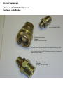
1
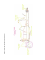
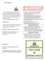
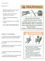
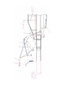
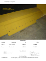
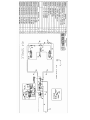
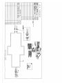
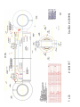
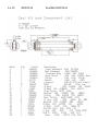
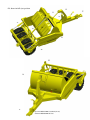
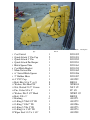
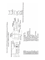
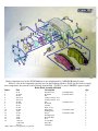
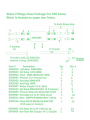
ICON
414
14 Yd. Rear Lowering Earthmover
Parts
And
Service
ICON Dealer Pre-Delivery Checklist
o Lubricate the machine with high temp grease, per the listing in the manual and
the decals on the machine.
o Plug in the hydraulic hoses per the information in the manual and on the
ICON hitch. The hoses have color coded bands and the instruction decal on
the hitch, will aid in the proper hookup. (the hydraulic hookup is only
recommended and should be adjusted to the owner/operator’s preference.
o Cycle the machine, checking performance and any possible leaks. The ICON
earthmover has been filled with hydraulic fluid and cycle checked at the
factory, however, air pockets can still exist, in the system. Check the tractor to
be sure the hydraulic valves have been adjusted to maximum flow.
o Plug in the safety lights and check the function of the stop and turn signals.
o If the machine is equipped with the optional brake package, plug the
connector into the tractor receptacle. By moving the tractor forward and
applying the brakes, resistance should be felt, from the scraper.
NOTE: ICON products are a fully assembled as possibly allowed for shipping.
Hydraulic systems are filled and cycle tested at the factory, if assembly of those
components can be allowed for shipping. Every effort is taken by ICON to simplify
predelivery by the ICON Dealer.
Should you have any questions in regard to setup or predelivery, please contact
ICON Product Support for assistance.
ICON Dealer Delivery Check List
o Give the ICON Operation/Service/Parts Manual to the Owner/Operator and
show where it may be kept on the machine.
o Have the Owner/Operator read the safety and maintenance section of the
Manual, review and answer all questions in regard. Also, review the ICON
Warranty with the Owner.
o Complete and sign the Warranty Registration Form and have the Owner read
the sign the form. Mail the Warranty Registration to ICON immediately. Write
in the model, date of purchase, and Dealer name and phone number in the area
provided in the Manual for the benefit of future questions, service, and parts.
o Emphasize that any additional Operators on the ICON machine should read
the safety section of the manual and receive instruction from an experienced
ICON Operator before proceeding.
o After 24/36 hours of running, the machine should be checked by the Dealer
according to the enclosed check list.
o Only high temp grease is recommended for use in the axle housings on the
ICON Earthmovers.
NOTE: Proper instructions to the ICON Owner/Operator on safety, operation,
maintenance and timely lubrication is essential for the longevity of the machine.
ICON Industries Commercial Earthmover
Assembly, Lube and Check List
____1. Install cutting bits, Torque retaining bolts.
____2. Locate and pin rear lift assembly. Install lift
cylinders. Torque all retaining bolts.
____3. Position and pin eject wall. Install eject
cylinder and linkage. On Series D Models
pin the floor and install cylinder.
Torque all retaining bolts. Install the depth gauge components.
____4. Locate and pin front gate and gate lift assembly.
Install lift cylinder. Torque all retaining bolts.
____5. Install front swivel hitch assembly. Torque all retaining bolts.
____6. Install axle and wheel components. Torque all retaining bolts.
Inflate tires to required PSI.
____7. Locate and assemble all hydraulic fittings, hoses and pipes. If
applicable, install tandem option package. Install front hose
holder assembly. Properly tighten fittings, taking care not to
overtighten. Install the proper markings to each hose and apply color coded hose wrap.
____8. Install safety lighting components, route wiring and install plug
retainer. Cycle and check lighting system with 12 volt system
tester.
____9. Lubricate all moving components with high temperature grease.
___10. Fill hydraulic systems with Mobil 424 hydraulic oil. Using
hydraulic pump, activate all moving parts and bleed air from the
system. Hold 3000 PSI hydraulic pressure against all cylinders,
fittings, and hoses for a minimum of 4 minutes. Check all
components for leaks.
___11. If the optional brake assembly is installed, check and cycle
brakes, bleed air if necessary.
___12. Calibrate the depth gauge.
Clean and touch up paint the machine. Attach manual/container.
Make sure each hyd. accumulator is charged to (650psi. on 800 series, 350psi on 18D’s)
___13. Apply the serial tag, operations, lube and identification decals.
Attach ICON check list to the front of the machine. Warranty
info and Dealer 36 hr. check list is located in the manual.
___14. Check safety stops to be sure that each properly engage and
lock the components in a safe and secure manner.
ICON Supervisor Signature: All of the above listed assembly and check
functions have been completed per my rigid standards.
____________________________________________________
Serial #______________
Date_________________
Checked By
__________________________________
Supervisor
Swivel Hitch Stamp____________________________
Owner’s Copy
ICON Industries Commercial Earthmover
Assembly, Lube and Check List
____1. Install cutting bits, Torque retaining bolts.
____2. Locate and pin rear lift assembly. Install lift
cylinders. Torque all retaining bolts.
____3. Position and pin eject wall. Install eject
cylinder and linkage. On Series D Models
pin the floor and install cylinder.
Torque all retaining bolts. Install the depth gauge components.
____4. Locate and pin front gate and gate lift assembly.
Install lift cylinder. Torque all retaining bolts.
____5. Install front swivel hitch assembly. Torque all retaining bolts.
____6. Install axle and wheel components. Torque all retaining bolts.
Inflate tires to required PSI.
____7. Locate and assemble all hydraulic fittings, hoses and pipes. If
applicable, install tandem option package. Install front hose
holder assembly. Properly tighten fittings, taking care not to
overtighten. Install the proper markings to each hose and apply color coded hose wrap.
____8. Install safety lighting components, route wiring and install plug
retainer. Cycle and check lighting system with 12 volt system
tester.
____9. Lubricate all moving components with high temperature grease.
___10. Fill hydraulic systems with Mobil 424 hydraulic oil. Using
hydraulic pump, activate all moving parts and bleed air from the
system. Hold 3000 PSI hydraulic pressure against all cylinders,
fittings, and hoses for a minimum of 4 minutes. Check all
components for leaks.
___11. If the optional brake assembly is installed, check and cycle
brakes, bleed air if necessary.
___12. Calibrate the depth gauge.
Clean and touch up paint the machine. Attach manual/container.
Make sure each hyd. accumulator is charged to (650psi. on 800 series, 350psi on 18D’s)
___13. Apply the serial tag, operations, lube and identification decals.
Attach ICON check list to the front of the machine. Warranty
info and Dealer 36 hr. check list is located in the manual.
___14. Check safety stops to be sure that each properly engage and
lock the components in a safe and secure manner.
ICON Supervisor Signature: All of the above listed assembly and check
functions have been completed per my rigid standards.
____________________________________________________
Serial #______________
Date_________________
Checked By
__________________________________
Supervisor
Swivel Hitch Stamp____________________________
Product Support Copy
Table Of Contents
A. Product Warranty
B. Scheduled Maintenance
C. Safety Section
D. Axle Adjustment
E. Damage While Pushing
F. Mounting/Dismounting Of Earthmover
G. 400 Series Parts Listing
H. 400 Series Components
I. Bolt Listing
J. Component Photos
K. Swivel Hitch
L. Hub/Axle Assy.
M.Brake Components
N. Cutting Edges & Components
O. Accumulator NA on 414
P. Hydraulic Components
Q. Decal & Safety Sticker Location
R. Axle Seal Replacement
Inside Front Cover
Scheduled Maintenance
A quality high temperature grease should be used when lubricating the machine. Most areas
of lube are scheduled daily, (8 to 10 hours or running). There are app. 26 grease zerks on all
ICON models, that should be greased daily. And an additional 2 zerks per axle, that should be
greased weekly, with 3 pumps of grease. Reference to their location is listed in the grease
guide, at the front of this book.
All bolts are torqued at the factory during assembly. After 24-36 hours of running, the
Dealer service should recheck the torque on the hitch, wheel, axle, and pin retaining bolts.
Each time the machine is greased, the operator or maintenance should look at these areas and
the bolts involved, to be sure none are working loose. After each 1000 hours of operation
with the machine, the above mentioned locations should be checked, and retorqued, per the
torque chart at the back of the book. The axle nuts should be adjusted the initial dealer visit.
Adjustment procedure is described in the back of this manual.
For safety, identification, and general information, all missing or damaged decals on the
machine should be replaced.
The ICON earthmovers have the interior of the bowl painted with a carbon base graphite
paint, which rejects dirt. Should that paint wear off over a period of time, replacement paint
may be ordered by the gallon through the original dealer.
The cutting bits for the earthmovers are available through ICON. The bevel is reversed as
compared to the normal bits, in order to make loading easier in tough ground. The reverse
bevel will not have the same longevity in wear as the normal bevel. Replacement bits may be
ordered from ICON, or you Dealer, refer to the cutting edge section of this manual for size
and part number.
All retaining pins have replaceable bushings. Watch the pin locations in action to review for
loose and worn operation.
Remember, the longevity of your machine will depend on proper operation and
maintenance.
Warning!
To prevent a hazardous situation, which if not avoided can result in injury or death, read
and follow these instructions!
Read and understand the operator’s manual before operating the machine. Allow no one to
operate the machine before reading the manual and being instructed on the proper operation.
Before servicing the machine, block the wheels, shut off the tractor, set the brakes, and
remove the key. If working under the machine, block the machine up for a safe and secure
working area. Apply any safety stops provided.
When working with hydraulic lines, cylinders, or fittings, wear protective clothing and
safety glasses to guard against high pressure oil leaks.
Do not allow anyone on, or near the machine while it is running, or in motion.
Do not operate the machine on a steep incline or slope that could create an imbalance or
rollover.
Grease Guide For 400 Series Earthmovers
Safety Section 3a
Safety Section 3b
Foreword
Literature Information
Maintenance
This information should be stored in the
literature holder located on the machine.
This manual contains safety information,
operating instructions, lubrication and
maintenance information.
Some of the photographs or illustrations in the
publication show details that can differ slightly
from your personal machine. Shields and covers
may have been removed to allow for
illustrations.
Constant improvement and knowledge of
product design may cause changes to your
personal machine that is not listed in this manual.
Read, understand, and keep this manual with the
machine to aid in repairs, adjustment, service and
parts identification.
Whenever a question arises regarding your
machine, or this manual, please contact Product
Support for assistance.
The maintenance section is a guide to
machine care. The illustrated step by step
procedures covers the most important of the
maintenance schedule. Regular routine
lubrication is described in less detail.
Safety
The safety section of this manual lists basic
safety precautions. In addition, this section
shows the location of safety signs and decals
used on this machine.
Read and understand the basic precautions
listed in the safety section before operating or
performing lubrication, maintenance or repair
work on this machine.
NOTE: Before any service or repair work is
performed, make certain that all safety stops
are in place.
Be certain to remove all safety stops when
repairs are complete.
Operation
This operation section is a reference guide for
the new operator and a refresher for the
experienced operator. Operating techniques
shown are basic, skill and technique will increase
with knowledge and usage of the machine.
Maintenance Intervals
Normally, all lubrication should be on a
daily basis. However, certain locations only
require lubrication on a weekly basis or
require a specific quantity. These locations
will be marked clearly, showing and
describing requirements.
Under extremely severe, dusty/wet/sandy
conditions, or if the haul is long and rough,
more frequent lubrication and inspection of
highly stressed areas is recommended.
Safety Section
General Hazard Information
Safety Section
General Hazard Information
A “Do Not Operate” warning tag or similar
warning tag should be attached to the start switch
or controls before servicing or repairing the
machine.
Know the width of your equipment in order to
maintain proper clearance when you operate the
machine(s) near fences or boundary obstacles.
Be aware of high voltage power lines or buried
power cables. If the machine comes in contact
with these hazards, serious injury or death may
occur, from electrocution.
Wear a hard hat, protective glasses, and other
protective equipment, as required.
Do not wear loose clothing or jewelry that can
snag on controls or other parts of the machine.
Make sure all protective shields and covers are
secured in place on the machine.
Obey all local regulations for the disposal of
liquids.
Do not allow unauthorized personnel on the
machine
Unless you are instructed otherwise, perform
maintenance with the machines in the servicing
position. The operation and maintenance manual
will describe the proper position.
Never put maintenance fluids (hydraulic) into
glass containers. Drain all liquids into suitable
containers.
Trapped Pressure
Pressure can be trapped in a hydraulic system.
Releasing trapped pressure can cause sudden
movement of the machine. Use caution if you
disconnect hydraulic lines or fittings. High
pressure oil that is released, can cause a hose to
whip. High pressure oil that is released, can
cause oil to spray.
Fluid penetration can cause serious injury or
death.
Fluid Penetration
Pressure can be trapped in a hydraulic
system, long after the engine has been
stopped. The pressure can cause fluid or
fittings/ends to detach rapidly, if the pressure is not released properly.
Do not remove any hydraulic components
until pressure has been relieve, or personal
injury may result. Do not disassemble any
hydraulic components or parts until the
pressure has been relieved, or personal
injury may occur.
Always use a board or protective shield
when you check for high pressure leaks.
Hydraulic fluid is under extreme pressure
and can cause serious injury and possible
death. A pin hole leak can cause severe
injury. If fluid is injected into your skin, you
must seek treatment immediately. Seek
treatment from a doctor that is familiar with
this type of injury.
Containing Fluid Spillage
Care should be taken to prevent spillage of
hydraulic fluids during maintenance, testing,
and repair of the machine. Prepare to collect
any fluid with suitable containers before
opening any system containing fluids.
Obey all local regulations for the disposal
of liquids.
Improperly disposing of waste fluids can
threaten the environment. Potentially
harmful fluids should be disposed of
according to local regulations.
Always use leakproof containers when
you drain fluids. Do not pour waste onto the
ground, or into any source of water.
Safety Section
Crushing/Cutting Prevention
Support the machine properly before you perform
any repairs or maintenance beneath that machine.
Do not rely on the cylinders to hold the machine up.
If a control is moved or a hydraulic line breaks, the
machine can fall.
Never attempt adjustments while the machine is in
motion.
Stay clear of all rotating and moving parts.
If it is necessary to remove shields or panels for
repairs/maintenance, be certain to replace them
before using the machine.
When you strike a pin or retainer with force, chips
and other debris can fly off the object.
Make sure that no one can be injured by flying
debris before striking any object. To avoid injury to
your eyes, wear protective glasses when striking any
object.
Make certain that the cylinder stops are in place
before making any adjustment/repairs under the
machine.
The stop pins should be in place on the clam
before working around the front of the machine.
Line, Tubes and Hoses
Inspect all lines and hoses for wear and chaffing.
The hoses must be properly routed and have
adequate support and the clamps should be secure.
Tighten all connections to the recommended
torque.
Do not bend high pressure lines. Do not install any
lines that are bent or damaged.
Repair any lines that are loose or damaged.
Check lines, tubes and hoses carefully. Do not use
your bare hands to check for leaks. Use a board or
cardboard to check, as high pressure fluid can enter
soft tissue.
Tighten all fittings and clamps to proper torque
specs.
About the ICON Limited Warranty……..
The ICON 400 Series scraper is designed with rear lowering and a push bumper (optional) on
the rear. The responsibility of use of this push bumper is left up to the discretion of the owner and
operator.
When push loading a pull type scraper, there are many issues to contend with so as not to
damage the scraper or the pull type tractor. The most important is the operator. The push tractor
can be an issue. Size and power must be kept within reasonable range. Should the pull tractor
operator put the scraper bit too deep into the ground, damage can occur due to undue stress on the
frog of the scraper. A straight push is necessary. Out of line or side stress can damage the rear
frame and possibly the scraper tires. Hard hits on link up with the push bumper can also damage
the machine. Whether loading single or tandem machines, care must be taken not to jackknife the
machines. Trained operators and common sense will create less damage and downtime. When
pushing in a bogged down or stuck condition, extreme care must be taken so as not to side stress
or damage the rear frame.
Due to the many ways in which the scraper can be damaged while pushing.
ICON will not Warranty damage to the scraper occurred while pushing.
NOTE: The ICON hitch is designed for safety, and one man operation — However, as with any moving part, the
potential for injury is present. Be aware of your surroundings while backing. Make certain no one is between the
scraper and the tractor while backing. Keep hands, feet and all body parts away from any machine component
that pivots, swings, or moves in any way, to avoid a potential injury.
Lock Down Ears
snap pin
Lock Down Pin
2000519 complete
Back the power unit into position, attach the hydraulic lines.
Pull the snap pin and slide the lock down pin out, allowing
the lock down ears to pivot forward.
(shown in the adjoining photo)
Position the swivel hitch above the quick hitch, and
hydraulically lower it into the cradle of the quick hitch.
Pivot the lock down ears over the adapter and replace the
lock down pin and snap pin. Valve #1 should be placed in
the #1 outlet (raise/lower) # 2 should control the gate/wall.
If the machines are being pulled as a tandem unit, Valve #3
should control the gate/wall of the tandem machine and Valve
#4 should control the raise/lower of the tandem machine.
This hook up is only recommended, the operator should
adjust for his/her own convenience.
Shown below is the current hydraulic configuration of the 800 Series Challenger. The covers are marked with a + or -, and the
ICON hoses are marked accordingly. Also the optional brake hook up is shown.
NOTE: High Pressure fluid can cause serious damage to eyes and hands. See Safety Section for safe hookup procedures.
Bolt Listing For 400 Series Earthmovers
Component
BH
NW
Qty
4
4
Description
Bolt, Hex 3/8x5” gr5
Nut, Whiz 3/8”
Hose Support
BP
WFH
NJ
20
20
20
Bolt, Plow 1x2 1/2” gr8
Washer, Flat, Hard
Nut, Jam 1” gr8
Cutting Edges & Frost Bit
BP
WFH
NJ
10
10
10
Bolt, Plow 3/4x2 1/2” gr8
Washer, Flat, Hard 3/4”
Nut, Jam 3/4” gr8
Side Cutting Edges
NJL
WFH
4001440
2
2
2
Nut, Jam Nyloc 1 1/2” gr5
Washer, Flat, Hard 1 1/2”
Key, Woodruf 1 1/8x1/4”
Clam Pins
BH
WFH
NL
8
12
12
Bolt, Hex 1 1/2x3” gr5
Washer, Flat , Hard 1/2”
Nut, Nyloc 1/2” gr2
Rear Frame Hyd. Clamps
BH
WFH
NH
6
6
6
Bolt, Hex 1 1/2”x6 gr8 SP
Washer, flat, Hard 1 1/2”
Nut, Hex 1 1/2” gr8
Swivel Hitch To Bracket
BP
WFH
NJ
6
6
6
Bolt, Plow 3/4x3” gr8
Washer, Flat, Hard 3/4”
Nut, Jam 3/4” gr8
Rear Side Cutting Edges
BH
BH
4
8
Bolt, Hex 1/2x2 gr5
Bolt, Hex 1x9” gr8
Axle Clamp Bolts
BH
WF
WFH
6
6
6
Bolt, Hex 1/2x1” gr5
Washer, Flat 1/2”
Washer, Flat, Hard 1/2”
Front Hose Holder Springs
BH
WFH
20
20
Bolt, Hex 7/8x3” Fine gr8
Washer, Flat, Hard 7/8”
Wheel Bolts
Bolt Listing Cont.
Component
BH
BH
WF
WFH
Qty
4
10
14
14
Description
Bolt, Hex 3/4x1 3/4” gr8
Bolt, Hex 3/4x1 1/2” gr8
Washer, Flat 3/4”
Washer, Flat, Hard 3/4”
Hold Downs For All 2 1/2” Pins Except ICO0222
BH
WF
WFH
NH
WF
WFH
1
1
1
1
1
1
Bolt, Hex 3/4x2 1/2” gr8
Washer, Flat 3/4”
Washer, Flat, Hard 3/4”
Nut, Hex 1 1/2” gr8
Washer, Flat 1 1/2”
Washer, Flat, Hard 1 1/2”
Center Rear Frame Pin ICO0222 Hold Down
4000067
4000591
4000720
8
8
3
Zerk Straight 1/8”
Zerk 1/8” 90 Degree
Adaptor 1/8-27-1/8NPT 90 ST Elb
Zerks
4000923
BP
2
2
Pin, Clevis 1/2x4 1/2”
Bridge Pin 1/8”
Rear Cyl. Stops
BH
WFH
NH
1
1
1
Bolt, Hex 3/4x3” gr8
Washer, Flat, Hard 3/4”
Nut, Hex 3/4” gr8
Depth Gauge Assembly
WF
BH
NW
BH
BH
6
2
4
1
1
Washer, Flat 1/2”
Bolt, Hex 1/2x1” gr5
Nut, Whiz 1/2”
Bolt, Hex 1/2x10” gr5
Bolt, Hex 1/2x6” gr5
Front Hose Cover @ Hyd. Block
BC
WFH
NW
14
14
14
Bolt, Carriage 3/4x1 1/4”
Washer, Flat, Hard 3/8”
Nut, Whiz 3/8”
Wear Strips To Swing Floor
NL
1
Nut, Nyloc 5/8” gr5
Axle Wrench Hold Down
BH
WFH
8
8
Bolt, Hex 1/2x1 1/2” gr5
Washer, Flat, Hard 1/2”
Front Hose Cover
Bolt Listing cont.
Component
Qty
BH
NH
WFH
8
8
8
Description
Bolt, Hex 1x3 1/2” gr8
Nut, Hex 1” gr8
Washer, Flat, Hard 1”
Axle Extender On Optional 26.5 Tires (Not Used On 418)
BH
WFH
NH
8
8
8
Bolt, Hex 5/8x2” gr5
Washer, Flat, Hard 5/8”
Nut, Hex 5/8” gr8
Rear Mud Scrapers
BH
WFH
NL
4000923
BP
1
1
1
1
1
Bolt, Hex 1x6” gr8
Washer, Flat, Hard 1”
Nut, Nyloc 1” gr5
Pin, Clevis 1/2x4 1/2”
Bridge Pin 1/8”
Gate Safety Stop
BH
NH
WFH
2
2
2
Bolt, Hex 1/2x4” gr5
Nut, Hex 1/2” gr5
Washer, Flat, Hard 1/2”
Side Hose Clamps
Parts Listing
414 S
Ref#
1. ICO0432
2. ICO0358
3. ICO2172
ICO2173
4. ICO0523
5. ICO0219
6. ICO1133
7. ICO0222
8. ICO0295
9. ICO1145
10. ICO0235
11. ICO1146
12. ICO0301
13. ICO1138
14. ICO1142
15. ICO1141
16. ICO0266
17. ICO0340
18. ICO0267
19. 4001295
20. 4001315
21. ICO0239
22. ICO1147
23. ICO1144
24. 2000513
25. ICO0488
26. ICO0335
27. ICO2112
28. ICO1070
29. ICO1143
30. ICO0254
31. ICO0255
32. ICO0244
33. 4000914
34. 2000460
35. 4000851
36. 4000958
37. 4000922
38. 4001034
39. 4001036
40. 4001037
41. 4000419
42. 4000911
43. 4000921
44. 4000623
45. 4000924
Part #
Description
Front Hose Bracket
Hose, Spring
Cutting Edge, (left side)
Cutting Edge, (right side)
Pin, Gate Tapered
Pin, 2 1/2” x 11 7/8”
Pin, 2 1/2” x 5 3/8”
Pin, 2 1/2” x 18 5/8”
Gate Link
Gate Arm
Hose Support
Depth Gauge
Gate (400 Series)
Rear Frame (400 Series)
Swing Floor (400 Series, 10/01/06)
Main Frame (400 Series)
Pin, 1 1/2” x 60 3/4” Floor Pin
Swing Floor Wear Strip
Floor Hinge Spacer
Tire, 23.5x25 16 ply Titan
Rim, 19.25 (5 pc. for 23.5)
Rear Cyl. Stop
Gate Safety Stop
Front Hyd. Shield
Hub Assy. (29” wide)
Axle Clamp w/groove
Axle Nut Wrench
Tandem Coupler Plate
Tandem Drawbar
Axle Extension (400 Series) NA w/26.5 tires
Rear Pin Spacer
Floor Hinge Spacer
Lift Cyl. Spacer (rear frame)
Bushing QD 2.5ID SF STL 2.5 (used w/ICO0222)
HD 360 Cast Swivel Hitch
Cutting Edge (7/8x13x35 3/4”)
Cutting Edge (7/8x16x48)
Cutting Edge (Rear)
Hyd. Cyl. (6 1/2x22 371/4”)
Hyd. Cyl. (4x50 63 3/4”)
Hyd. Cyl. (5x22 37 1/4”)
Manual Holder
Hyd. O-Ring (4 3/8OD-4ID)
Hyd. Valve Block Sequence
Hyd. Pilot Chk Valve CKEB-XCN
Hyd. Counter Valve CBEA-LHN
Qty.
1
3
1
1
2
5
7
1
1
1
1
1
1
1
1
1
2
2
2
2
2
2
1
1
2
2
1
1
1
2
1
1
2
2
1
2
1
2
1
1
2
1
2
1
1
1
400 Series Parts Listing Cont.
Ref#
Part #
46. 4000925
47. 9900007
48. 2000546
49. 2000548
50. 5001066
51. 5001067
52. 5001075
53. 5001076
54. 2000547
55. ICO2113
56. ICO2111
57. ICO0249
58. ICO0257
59. 5000617
60. 5000618
61. 4000902
62. 4000954
2000541
2000542
2000543
2000544
ICO1070
ICO2112
5000617
5000618
2000545
2000540
4001471
4001272
Description
Qty.
Hyd. Sequence Valve SCEA-LAN
Tandem Rear Hose Supports
Bolt Kit (414S)
Bolt Kit (414T)
Hydraulic Fitting Kit (S)
Hydraulic fitting Kit (T)
Hydraulic Hose Kit (S—2 v)
Hydraulic Hose Kit (T—2v)
Decal Kit 414
Front Hydraulic Covers
Mud Scrapers
Depth Gauge Retainer
Clamp, Hyd. Line 2x3 1/2”
Hose Clamp—Plastic
Hose Clamp—Cover Plate
Bushing 300251200
Bushing 300259200
1
2
1
1
1
1
1
1
1
2
2
1
4
8
4
15
1
Optional
23.5 to 26.5 Tire Upgrade
Aux. Push Block
Brake Package
Safety Light Package
Components Included In Tandem Package
U Assy Tandem Drawbar
Tandem Coupler Plate
Hose, Clamp Plastic
Hose, Clamp Covers
Tandem Hydraulics
Hub Assy 33”
Tire, 26.5x25 16ply Titan
Rim, 22x25 (5 pc. for 26.5)
(16)
(8)
1
2
ICO0346
ICO0295
Gate Link
ICO0301
3
4
ICO1142
ICO1141
ICO1138
Rear view of the 414S, 2v single, with 23.5 tires
(56) ICO2111
Shown are the spacer blocks used with
the 23.5 tires. If the optional 26.5 tires
are used, these blocks are not needed,
due to longer length of the axles.
Clam Pivot Pin (ICO0523)
Shown is the ICO0523 Clam Pivot Pin. The tapered pin is threaded for an 1 1/2” nut.
NOTE: The nut should be torqued to 600 ft. lbs.
The axle spacer is held in place by (4) 1 x 3 1/2” bolts
Axle Extension ICO1143
Axle Clamp Bolts 1 x 9”
Components of the 414 Earthmover
(9) Gate Arm ICO0346
(5) ICO0219 pin
(3
6
8)
2
x2
O
(23) IC
(12) Gate ICO0301
(22) Gate Safety Stop ICO1147
11 44
(55) IC
O
2113 F
ront Hy
d. Cove
r
(5) ICO0219
(11) ICO1146
(14) ICO1142
(21) ICO023
9
(6) ICO0420
(40
)
400
103
7
(6) ICO0420
Components (cont.) Center Rear Frame Pin
(39) 4001036
1 1/2” nut
& washer
(7) ICO0222
4000902
400954
(22) ICO0254
(33) 4000914
(33) 4000914
Same center pin configuration
in tandem operation.
Front End Components Of 400 Series
(1) ICO0432
(5) ICO0219
(2) ICO0358
Front view of tandem machine
Inside view of gate cylinder pivot . (from front)
418 Rear Frame, shown as single
unit. The pin is used for cable
attachment, should the machine
require being pulled from a stuck
situation.
ICO0218
The tandem option contains the rear
hydraulics and a slide in drawbar with
the ICON Quick Attach. It is pinned in
place with the ICO0218 pin.
ICO1070 Tandem Drawbar
ICO0218
Shown is the Heavy Duty Swivel Hitch. It is standard on the 400 series. It features a full 360 degree rotation,
cast yoke style, that attaches to the ICON Quick Attach drawbar.
It is rated for 600 hp.
The Quick Attach Drawbar and U assembly
13 , 14, & 15
6
8
17
5
1
16
3&4
17
2
7
11 & 12
Ref #
22
Description
Cast Swivel
2 Quick Attach 3” Pin Cap
3 Quick Attach 3” Pin
4 Quick Attach Pin Keeper
5 Hitch Spacer Tube
6 Cast Hitch Bracket
7 Main Vertical Pin
8 6” Swivel Hitch Spacer
9 2” Rubber Hose
10 4” PVC Cap
11 Bolt, Hex 3/4 x 2” gr. 8
12 Washer, Flat Hard 3/4”
13 Nut, Slotted 2 1/2” Course
14 Pin, Cotter 3/8 x 5”
15 Washer, Flat 2 1/2” Hard
16 Bolt, 5/8 x 3”
17 Bushing
18 O-Ring 8 7/8x8 1/2” ID
19 O-Ring 7 3/8x7” ID
20 O-Ring 5 7/8x 5” ID
21 O-Ring 4 x 3 5/8” ID
22 Wiper Seal 3 1/2 x 3 1/4”
1
Qty
Part #
1
2
1
1
1
1
1
1
1
1
8
8
1
1
1
3
4
1
1
2
2
2
ICO1092
ICO1093
ICO2052
ICO2051
ICO1061
ICO1055
ICO1062
ICO1086
ICO1087
4001292
BH 3/4
WFH 3/4
NS 2 1/2
PC 3/8
WFH 2 1/2
BH 5/8
4001271
4001272
4001286
4001275
4001274
4001298
U Assembly Drawbar and Swivel Hitch
4001050
ICO0368
ICO0370
ICO0121
ICO0369
The pivot pin
ICO0370 is held
in place with (2)
3/16 x 3 1/2”
cotter pins
ICO0123
Above are the components of the ICON Quick Attach System. Back the power unit close enough to hook the
hydraulic lines. Pull the snap pin , remove the lock down pin and pivot the ears back , out of the way.
Hydraulically raise the tongue of the machine, until it clears the u assembly then back the assembly under the
hitch, into position. Lower the hitch into the u assembly cradle and pivot the lock down ears over the adepter ,
replace the lock down pin and snap pin. Hook up is complete.
To dismount the unit, reverse procedure.
Cutting Edges & Components
Wear Strip—ICO0340
1/2 x 1 1/2” Carriage Bolts (12)
Cutting Edges
Location
Dimensions
#
CAT #
Side (2)
7/8 x 13 x 35.75
4000851
178-4080
Center
7/8 x 16 x 48
4000958
174-8002
Bolts Per Blade
4000851 ……………..6
4000958……………...8
ICO0206L & R
Cutting Edges
1 x 2 1/2” gr. 8 Plow Bolt
1” gr. 8 Jam Nuts
1” Hardened Flat Washers
Side Cutting Edges
Each side requires (5) 3/4 x 2 1/2” Plow Bolts, Hard Washers and Hex Nuts.
Hydraulics for 2 valve 400 series
The 2 valve sequence block components.
Valve Seq. Block 4001452 (4)
Pilot Check Valve CKGB-XCN 4001451 (3)
Counter Valve CBGB-LHN 4001449 (1)
Sequence Valve SCGA-LAN 4001450 (2)
2
2
4
3
4
1
behind
hose
Hydraulic Fitting listing For Single & Tandem 418’s
Single 5001066
Part #
5000835
5001068
5001071
5001070
5001072
5001073
Description
Qty
Pioneer Male Ends 8010-16P 10FB
Hyf—Adap 8MFFORx90
Hyf—Adap 12MB-8MFFOR
Hyf—Adap 8MFFOR-12MB90
Hyf—Adap 8MFFORTEE
Hyf—Adap 8MFFORBH-LN
4
2
5
9
2
____________________________________________________________________________________
Tandem 5001067
5000835
5001068
5001071
5001072
5001070
5001073
5001014
Hyf-Pioneer Male 8010-16P 10FB
Hyf—Adap 8MFFOR-8FFORx90
Hyf—Adap 12MB-8MFFOR
Hyf-Adap 8MFFORTEE
Hyf—Adap 8MFFOR-12MB90
Hyf—Adap 8MFFORBH-LN
Hyf—Pioneer FEM END 8250-16
8
2
5
2
9
6
4
Hydraulic Hose List for Single and Tandem 414 Series
Single 2V
Part #
5001077
5001078
5001079
5001080
5001081
5001082
5001083
5001084
5001085
5001086
5001087
5001089
5001090
Description
Hose, 8FFORX-8C12x177”-10MB
Hose, 8FFORX-8C12x168”-10MB
Hose, 8FFORX-8C12x287”-8FFOR
Hose, 8FFORX-8C12x212”-8FFOR
Hose, 8FFORX-8C12x311”-8FFOR
Hose, 8FFORX-8C12x45”- 8FFORX
Hose, 8FFORX-8C12x37”-8FFORX
Hose, 8FFORX-8C12x124”-8FFOR
Hose, 8FFORX-8C12x70”-8FFORX
Hose, 8FFORX-8C12x30”-8FFORX
Hose, 8FFORX-8C12x130”-8FFOR
Hose, 4FJX-3CITx49”-2MP
Hose, 4FJX-3CITx53”-2MP
Qty
2
2
1
2
1
1
1
1
1
1
1
2
1
Tandem (In addition to above)
5001088
Hose, 8FFORX-8C12x353”-8FFOR
4
5 x 22
# 4001037
Seal Kit # 4000961
6 x 22
#4001236
Seal Kit #4001434
4001036 w/bushings
Decal Set For 400 Series
Part #
1
2
3
4
5
6
7
8
9
10
11
12
13
14
15
16
17
18
19
20
21
12—15
4000931
4000935
4000937
4000938
4000940
4000941
4000960
4001473
4000396
4000702
4000949
4001435
4001445
4001446
4001248
4000372
4001432
4001415
4001495
4001477
4001497
Description
Qty
Decal, “Warning” High Pressure
Decal, “Safety/Operation/Parts”
Decal, “3 Pumps Of Grease Weekly”
Decal, “Grease Daily”
Decal, “Danger” Pinch
Decal, “ Danger” To Prevent A Hazard
Decal, “ICON” 4”
(Both sides)
Decal, Depth Gauge
Decal, Gate Gauge A-B-C-D-E
Decal, Reflective Tape
Decal, Hyd. Hose Color Code
Decal, Tire Pressure/Torque (26.5 -23.5)
Decal, Safety Stops
Decal, Remove Safety Stops
Decal, Horsepower Limits (400) (500 on 418)
Decal, Caution, Moving Parts
Decal, USA Flag
Decal, Made in USA
Decal, 400 Series (414-416-418)
Decal, T (tandem) or S (single)
Decal, Graphic Side Stripes
2
1
2
26
4
1
4
1
1
4pc. 18”
1
2
3
3
1
4
2
2
1 set
2
1 set
10
7
1—6
8
19-20
8
1
1
8
14—4
7
6
22
11
18
21
20
5 - Grease Daily (26) ea. zerk
6
17
13
ICON
418 Rear Lowering Earthmover
Parts & Service
418 Parts Listing
Item #
1.
2.
3.
4.
5.
6.
7.
8.
9.
10.
11.
12.
13.
14.
15.
16.
17.
18.
19.
20.
21.
22.
23.
24.
25.
26.
27.
28.
29.
30.
31.
32.
33.
34.
35.
36.
37.
38.
39.
40.
41.
42.
43.
44.
45.
46.
47.
48.
49.
50.
51.
52.
53.
Part #
ICO2151
ICO2152
ICO0432
ICO0358
ICO2172
ICO2173
ICO0523
ICO1133
ICO0219
ICO0222
ICO0295
ICO0346
ICO0235
ICO0239
ICO0244
ICO1144
2000461
ICO0250
ICO2118
ICO2119
ICO2117
ICO0254
ICO0255
ICO0256
ICO0257
ICO0340
ICO0267
ICO0335
ICO2113
4000914
ICO0488
4000636
4000657
2000512
4001034
4001036
4001037
4000851
4000951
4000922
4000419
4001449
4001450
4001451
4001452
4001267
9300901
ICO0464
ICO0205
ICO0350
ICO1118
ICO1117
SCR2078
Description
Front Hose Cover (r side)
Front Hose Cover (l side)
Front Hose Bracket
Hose Spring Assy.
Cutting Edge (left side)
Cutting Edge (right side)
Tapered Gate Pin
Pin, 2 1/2”x5 3/4” Ball Joint
Pin, 2 1/2”x11 7/8”
Pin, 2 1/2”x18 5/8”
Gate Link
Gate Arm
Hose Support
Rear Cyl. Stop
Lift Cyl. Spacer
Hyd. Shield
MD Cast Swivel Hitch (optional)
Gate
Rear Frame
Swing Floor
Main Frame
Rear Pin Spacer
Floor Hinge Spacer
Floor Pin, 1 1/2” x 66 3/4”
Hyd. Line Clamp
Swing Floor Wear Strip
Floor Hinge Spacer
Axle Nut Wrench
Axle Bolt Spacer
Bushing QD 2.5ID SF STL 2.5
Axle Clamp w/groove
Tire, 20.5x25-16 ply
Rim, 17x25 3 pc assy.
Hub Assy. 28” wide
Hyd Cylinder 6 1/2x22- 36 1/4”
Hyd. Cylinder 4x50 - 63 3/4”
Hyd. Cylinder 5x22 - 37 1/4”
Cutting Edge, 7/8x13x35.75”
Cutting Edge 7/8x16x60”
Rear Cutting Edge
Manual Holder
Hyd. Counter Valve CBGB-LHN
Hyd. Sequence Valve SCGA-LAN
Hyd. Pilot CHK Valve CKGB-XCN
Hyd. Valve Block Seq. #3
2 Gallon Accumulator
Accumulator Mount
Accumulator Mount
Gate Spacer
Gate Link Spacer
Pin Spacer 9/16”
Pin Spacer 7/8”
Wheel Bolt Spacer
Qty
1
1
1
3
1
1
2
7
5
1
1
1
1
2
4
1
1
1
1
1
1
1
1
2
4
2
2
1
4
2
4
4
4
4
1
1
2
2
1
2
1
1
1
1
1
1
2
1
4
2
8
5
40
418 Parts Listing - Cont.
54.
55.
56.
57.
58.
59.
60.
61
62.
63.
64.
65.
66.
ICO1147
ICO1146
2000470
2000587
2000585
2000460
5001092
5001094
2000551
2000547
2000203
ICO2021
ICO2053
Gate Stop
Depth Gauge
(Option) Brake Assy
(Option) Potentiometer
(Option) Potentiometer Tractor
SD Swivel Hitch
Kit, Hyd. Fittings (single)
Kit, Hose (single 2v)
Kit, Bolt 418 single
Kit, Decal 400 series
Kit, Lights
Brake Line Shield
821 Axle Nut
1
1
1
1
1
1
1
1
1
1
1
2
8
Parts Listing
55
7
13
54
2
1
17
24
9
6
3
4
12
18
11
13
20
36
8
37
7
10
21
19
5
24
8
34
418 shown in full eject position
12
17
11
35
37
36
20
21
40
55
18
54
17
Optional 2000461 MD Cast Hitch (shown)
Standard 2000460 HD 360 Cast
Rear Frame ICO2118
Main Frame ICO2117
A 4000902 and 4000954
bushing is used in the
center of the rear frame.
The 4000954 is slightly
oversized to allow easier
pin insertion.
Rear frame mounts to main frame using ICO1133 pins at each side and a center frame
pin ICO0222 and (2) 4000419 bushings
ICO0250 Gate.
Attaches to the main frame with (2) ICO0523 tapered
pins. These should be torqued to 650lbs.
The swing floor ICO2119. The cylinder attaches at the
top and allows the floor to pivot on (2) ICO0256 pins,
inserted at the bottom.
Wear Strips
Front view of the swing floor. The mounts
for the floor pins can be seen, along with the
side wear strip (ICO0340) mounting holes.
Gate Arm (ICO0346)
Gate Link (ICO0295)
Components of the 418
ICO0219
ICO0346
ICO0295
ICO1144
ICO1147
ICO2
15 1/ 2
ICO0250
152
ICO1146
ICO0239
ICO1133
400
103
7
ICO1133
418 in lowered position
ICO1133
40 0
103
7
ICO1133
4000922
418 shown in raised position
4001267
ICO0239
ICO2021
Tire 20.5x25 - 4000636
Rim 17x25 - 4000657
LT00055
5000908 brake coupler
5000844 welds
into coupler plate
5001014 Female
ICO0218
ICO1070
ICO0369
ICO0368
The Super Duty Cast Hitch is standard on all Models
A Medium Duty Option is available.
2000460
Shown is the 3” pin (ICO1094) used with the cast hitch. The top is milled to allow
the retainer plate (ICO1095) to bolt on using (3) 5/8 x 3” bolts.
13-14-15 under cap
6
10
8
9
1
20
zerk
16
21
5
4
3
zerk
17
2
12
11
1 1/2 x 6
(6)
zerk ea side
19
18
7
22 inside caps
Ref #
Qty
Cast Swivel
2 Quick Attach 3” Pin Cap
3 Quick Attach 3” Pin
4 Quick Attach Pin Keeper
5 Hitch Spacer Tube
6 Cast Hitch Bracket
7 Main Vertical Pin
8 6” Swivel Hitch Spacer
9 2” Rubber Hose
10 4” PVC Cap
11 Bolt, Hex 3/4 x 2” gr. 8
12 Washer, Flat Hard 3/4”
13 Nut, Slotted 2 1/2” Course
14 Pin, Cotter 3/8 x 5”
15 Washer, Flat 2 1/2” Hard
16 Bolt, 5/8 x 3”
17 Bushing
18 O-Ring 8 7/8x8 1/2” ID
19 O-Ring 7 3/8x7” ID
20 O-Ring 5 7/8x 5” ID
21 O-Ring 4 x 3 5/8” ID
22 Wiper Seal 3 1/2 x 3 1/4”
1
Description
Part #
1
2
1
1
1
1
1
1
1
1
8
8
1
1
1
3
4
1
1
2
2
2
ICO1092
ICO1093
ICO2052
ICO2051
ICO1061
ICO1055
ICO1062
ICO1086
ICO1087
4001292
BH 3/4
WFH 3/4
NS 2 1/2
PC 3/8
WFH 2 1/2
BH 5/8
4001271
4001272
4001286
4001275
4001274
4001298
Brake components used on the ICON Earthmovers are manufactured by CARLSLE Braking Systems.
Below is a list of the components currently used on the Earthmover brakes. ICON does not stock or supply
these components, they must be ordered directly from the Mfr. NOTE: Use only CARLISLE Approved parts.
Brake Head Assembly #419-888
Index
Part
Description
Qty.
1.
2.
3.
4.
5.
6.
7.
8.
9.
10.
11.
12.
13.
14.
15.
16.
84-35
43-1140
20-554
244-741-2
244-741-1
20-490
43-1299
80-717
93-986
49-402
*NSS
74-927
*NSS
*NSS
*NSS
+184-979
**306-7376
328-741
*These items not sold separately: see parts kit
Bleeder Valve
Bolt, Hex
Pin
Lining & Carrier Assy.
Lining & Carrier Assy.
Pin
Bolt, Hex
Washer
Plate, Cover
Plug, Piston
Packing Plug
Piston
Packing Piston
Retainer Ring
Boot
Torque Plate
Parts Kit
Lining Kit
(CAT #7K-4942)
(CAT #3V-0197)
(CAT #4V-7277)
(CAT #114-9304)
(CAT #114-9306)
1
4
2
1
1
2
6
6
1
2
2
4
4
4
4
1
1
1
Brake Components
Used on all ICON Earthmovers
Equipped with Brakes
5000906
M18x1.5MWO-10MJ
Front Brake Coupler
5000907
(Faster VF1815F-0.4M)
The male end is mounted on the rear of the lead scraper. (If a
tandem package is ordered).
It is standard on the AGCO Challenger tractors, if equipped
with the brake package.
Rear Brake Coupler
5000908
(Faster, VF-7/1815-M)
Cuttings Edges & Components
Wear Strip—ICO0340 (2 pcs)
1/2 x 1 1/2” Carriage Bolts (12)
Cutting Edges
Location
Side (2)
Dimensions
7/8 x 13 x 35.75
#
4000851
CAT #
178-4080
Center
7/8 x 16 x 60
4000951
174-8001
If a straight cut for finish work is required, a 13” center blade is available from CAT
Center SC
7/8 x 13 x 60
4000619
4T6620
Center
7/8 x 19 x 60 (More aggressive cut) 4001013
Bolts Per Blade
4000851 ……………..6
4000951……………...10
ICO0206L & R
ICO2172/2173
Cutting Edges
1 x 2 1/2” gr. 8 Plow Bolt
1” gr. 8 Jam Nuts
1” Hardened Flat Washers
Side Cutting Edges
Each side requires (5) 3/4 x 2 1/2” Plow Bolts, Hard Washers and Hex Nuts.
4” longer for deeper cut
Hydraulics for 2 valve 400 series
The 2 valve sequence block components.
Valve Seq. Block 4001452 (4)
Pilot Check Valve CKGB-XCN 4001451 (3)
Counter Valve CBGB-LHN 4001449 (1)
Sequence Valve SCGA-LAN 4001450 (2)
2
2
4
3
4
1
behind
hose
Hydraulic Hose Listing For 418 Single
5001096
5001097
5001098
5001099
5001100
5001101
5001102
5001103
5001104
5001140
5001106
5001139
2
2
1
2
1
1
1
1
1
1
1
1
Hose, 12FFORX-12C12x177”-12MB
Hose, 12FFORX-12C12x168”-12MB
Hose, 12FFORX-12C12x299”-12FFORX
Hose, 12FFORX-12C12x224”-12FFORX
Hose, 12FFORX-12C12x323”-12FFORX
Hose, 12FFORX-12C12x51”-12FFORX
Hose, 12FFORX-12C12x43”-12FFORX
Hose, 12FFORX-12C12x130”-12FFORX
Hose, 12FFORX-12C12x70”-12FFORX
Hose, 12FFORX-12C12x45”-12FFORX
Hose, 12FFORX-12C12x136”-12FFORX
Hose, 16MB-12C12x31”-12FFORX
Hydraulic Fittings For 418 Single
5001001
5001047
5000833
5000793
5000983
5001011
4
2
5
9
2
4
Hyf-Parker 3/4 Male End-12FB 1
Hyf-EL, 12FFORX-12MFFOR90
Hyf-Adpt. 12MB-12MFFOR
Hyf-EL, 12MFFOR-12MB90
Hyf-Tee, 12MFFORT
Hyf-12MFFORBH-LN
Components Added To Complete Tandem
5001001
5001011
5000977
5001096
5001107
4
4
4
4
4
Pioneer Male 3/4” 12MB
Hyf-12MFFORBH-LN
Pioneer Female 3/4” 12MB
Hose, 12FFORX-12C12x177”-12MB
Hose, 12FFORX-12C12x365”-12FFORX