1
SiBE12-908
Preliminary
Service Manual / Inverter Multi System with Humidifying G-Series
SiBE12-908
Printed in Japan 01/2009 B AK
SiBE12-908
Specifications, designs and other content appearing in this brochure are current as of January 2009 but subject to change without notice.
Inverter Multi System
with Humidifying
G-Series
[Applied Models]
Inverter Multi : Heat Pump
SiBE12-908
Inverter Multi System
with Humidifying
G-Series
zHeat Pump
Indoor Unit
CTXU25G2V1B
CTXU35G2V1B
CTXU42G2V1B
CTXU50G2V1B
Outdoor Unit
2MXU40GV1B
2MXU50GV1B
Table of Contents
i
SiBE12-908
ii
Table of Contents
SiBE12-908
Part 4
Function and Control
1. Main Functions........................................................................................2
1.1
1.2
1.3
1.4
1.5
1.6
1.7
1.8
1.9
1.10
1.11
1.12
1.13
1.14
Frequency Principle..................................................................................2
Thermostat Control...................................................................................4
Automatic Operation.................................................................................5
Programme Dry Function .........................................................................6
Airflow Direction Control...........................................................................7
Fan Speed Control for Indoor Units..........................................................8
HUMID HEAT Operation ..........................................................................9
Fresh Air Supply Ventilation ...................................................................14
2-AREA INTELLIGENT EYE ..................................................................16
Inverter POWERFUL Operation .............................................................18
ECONO Mode ........................................................................................19
NIGHT SET Mode ..................................................................................20
Other Functions......................................................................................21
Table for Special Modes.........................................................................23
2. Function of Thermistor ..........................................................................25
2.1 Heat Pump Model...................................................................................25
3. Control Specification .............................................................................27
3.1
3.2
3.3
3.4
3.5
3.6
3.7
3.8
3.9
3.10
3.11
3.12
3.13
3.14
3.15
Function and Control
Mode Hierarchy ......................................................................................27
Automatic switching for HUMID HEAT operation room..........................28
Frequency Control..................................................................................29
Controls at Mode Changing / Start-up....................................................31
Discharge Pipe Temperature Control.....................................................33
Input Current Control..............................................................................33
Freeze-up Protection Control .................................................................34
Heating Peak-cut Control .......................................................................34
Fan Control.............................................................................................35
Liquid Compression Protection Function 2.............................................35
Defrost Control .......................................................................................36
Electronic Expansion Valve Control .......................................................37
Malfunctions ...........................................................................................41
Forced Operation Mode .........................................................................42
Additional Function.................................................................................43
1
Main Functions
SiBE12-908
1. Main Functions
1.1
Frequency Principle
Main Control
Parameters
Additional
Control
Parameters
Inverter Principle
The compressor is frequency-controlled during normal operation. The target frequency is set by
the following 2 parameters coming from the operating indoor unit:
The load condition of the operating indoor unit
The difference between the room temperature and the set temperature
The target frequency is adapted by additional parameters in the following cases:
Frequency restrictions
Initial settings
Forced cooling operation
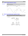
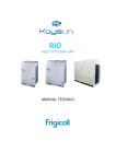
To regulate the capacity, a frequency control is needed. The inverter makes it possible to vary
the rotation speed of the compressor. The following table explains the conversion principle:
Phase
1
2
Drawing of
Inverter
Description
The supplied AC power source is converted into the DC power source for the present.
The DC power source is reconverted into the three phase AC power source with variable
frequency.
When the frequency increases, the rotation speed of the compressor increases resulting
in an increased refrigerant circulation. This leads to a higher amount of the heat
exchange per unit.
When the frequency decreases, the rotation speed of the compressor decreases
resulting in a decreased refrigerant circulation. This leads to a lower amount of the heat
exchange per unit.
The following drawing shows a schematic view of the inverter principle:
Refrigerant circulation rate (high)
DC
power
Amount of heat
exchanged air (small)
high speed
AC
power
Amount of heat
exchanged air (large)
high f
low f
Amount of heat
exchanged air (large)
Amount of heat
exchanged air (small)
low speed
50 Hz
freq=
constant 60 Hz
freq=variable
capacity=
variable
Refrigerant circulation rate (low)
2
(R2812)
Function and Control
SiBE12-908
Inverter Features
Main Functions
The inverter provides the following features:
The regulating capacity can be changed according to the changes in the outdoor air
temperature and cooling / heating load.
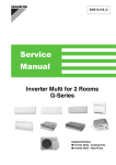
Quick heating and quick cooling
The compressor rotational speed is increased when starting the heating (or cooling). This
enables a quick set temperature.
Air discharge
temperature
45˚C
inverter
normal heat pump
Start
60
120
300
seconds
(R1187)
Even during extreme cold weather, the high capacity is achieved. It is maintained even when
the outdoor air temperature is 2°C.
Comfortable air conditioning
A detailed adjustment is integrated to ensure a fixed room temperature. It is possible to air
condition with a small room temperature variation.
Energy saving heating and cooling
Once the set temperature is reached, the energy saving operation enables to maintain the
room temperature at low power.
Frequency Limits
Forced Cooling
Operation
Function and Control
The following table shows the functions that define the minimum and maximum frequency:
Frequency limits
Low
Limited during the activation of following functions
Four way valve operation compensation. Refer to page 31.
High
Discharge pipe temperature control. Refer to page 33.
Input current control. Refer to page 33.
Compressor protection function. Refer to page 32.
Heating peak-cut control. Refer to page 34.
Freeze-up protection control. Refer to page 34.
Defrost control. Refer to page 36.
For more information, refer to “Forced operation mode” on page 42.
3
Main Functions
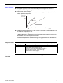
1.2
SiBE12-908
Thermostat Control
Thermostat control is based on the difference between the room temperature and the set point.
Thermostat OFF Condition
The temperature difference is in the zone A.
Thermostat ON Condition
The temperature difference is above the zone C after being in the zone A.
The system resumes from defrost control in any zones except A.
The operation turns on in any zones except A.
The monitoring time has passed while the temperature difference is in the zone B.
(Cooling / Dry : 10 minutes, Heating : 10 seconds)
Cooling / Dry
ON
Room temperature - set point
Cooling : –0.5˚C
Dry : –0.5˚C
C
B
Cooling : –2.0˚C
Dry : –2.5~–2.0˚C
A
OFF
(R4668)
Heating
Room temperature - set point
OFF
A
2.0˚C
B
C
0.5˚C
ON
(R9424)
4
Function and Control
SiBE12-908
1.3
Main Functions
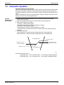
Automatic Operation
Automatic Cooling / Heating Function
When the AUTO mode is selected with the remote controller, the microcomputer automatically
determines the operation mode from cooling and heating according to the room temperature
and setting temperature at the time of the operation startup, and automatically operates in that
mode.
The unit automatically switches the operation mode to cooling or heating to maintain the room
temperature at the main unit setting temperature.
Detailed
Explanation of
the Function
1. Remote controller setting temperature is set as automatic cooling / heating setting
temperature (18 to 30°C).
2. Main unit setting temperature equals remote controller setting temperature.
3. Mode switching point are as follows.
� Heating → Cooling switching point:
Room temperature ≥ Main unit setting temperature +3.0 deg.
� Cooling → Heating switching point:
Room temperature < Main unit setting temperature –2.5 deg.
� Thermostat ON / OFF point is the same as the ON / OFF point of cooling or heating
operation.
4. During initial operation
Room temperature ≥ Remote controller setting temperature: Cooling operation
Room temperature < Remote controller setting temperature: Heating operation
Cooling Operation
Set point +3.0ºC
Set point +2.0ºC
=Thermostat OFF
Set point –2.0ºC
=Thermostat OFF
Set point –2.5ºC
Heating Operation
(R9417)
Ex: When the set point is 25°C
Cooling Operation → 23°C: Thermostat OFF → 22°C: Switch to Heating Operation
Heating Operation → 27°C: Thermostat OFF → 28°C: Switch to Cooling Operation
Function and Control
5
Main Functions
1.4
SiBE12-908
Programme Dry Function
Programme dry function removes humidity while preventing the room temperature from
lowering.
Since the microcomputer controls both the temperature and airflow volume, the temperature
adjustment and fan adjustment buttons are inoperable in this mode.
In Case of
Inverter Units
The microcomputer automatically sets the temperature and fan settings. The difference
between the room temperature at startup and the temperature set by the microcomputer is
divided into two zones. Then, the unit operates in the dry mode with an appropriate capacity for
each zone to maintain the temperature and humidity at a comfortable level.
Room temperature at
startup
Set temperature
X
Thermostat OFF point
Y
Thermostat ON point
Z
X – 2.5ºC
X – 0.5ºC
or
Y + 0.5ºC (zone B)
continues for 10 min.
X – 2.0ºC
X – 0.5ºC
or
Y + 0.5ºC (zone B)
continues for 10 min.
X – 2.0ºC
X – 0.5ºC = 17.5ºC
or
Y + 0.5ºC (zone B)
continues for 10 min.
24ºC or more
Room temperature at
startup
23.5ºC
~
18ºC
17.5ºC
18ºC
~
Zone C = Thermostat ON
Z
Zone B
Y
Zone B
+0.5ºC
Zone A = Thermostat OFF
(R6841)
6
Function and Control
SiBE12-908
1.5
Main Functions
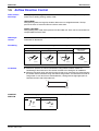
Airflow Direction Control
Power-Airflow
Dual Flaps
The large flaps send a large volume of air downwards to the floor. The flap provides an optimum
control area in cooling, heating, and dry mode.
Heating Mode
During heating mode, the large flap enables direct warm air straight downwards. The flap
presses the warm air above the floor to reach the entire room.
Cooling / Dry Mode
During cooling or dry mode, the flap retracts into the indoor unit. Then, cool air can be blown far
and pervaded all over the room.
Wide-Angle
Louvres
The louvres, made of elastic synthetic resin, provide a wide range of airflow that guarantees a
comfortable air distribution.
Auto-Swing
The following table explains the auto swing process for heating, cooling, dry, and fan :
Vertical Swing (up and down)
Cooling / Dry
Heating
Horizontal Swing
(right and left:
automatic)
Fan
5˚
15˚
30˚
30˚
50˚
30˚
55˚
70˚
65˚
(R8316)
(R8315)
3-D Airflow
30˚
80˚
45
˚
˚
45
65˚
(R8317)
(R8318)
Alternative repetition of vertical and horizontal swing motions enables uniform air-
conditioning of the entire room. This function is effective for starting the air conditioner.
When the horizontal swing and vertical swing are both set to auto mode, the airflow become
3-D airflow and the horizontal swing and vertical swing motions are alternated. The order of
swing motion is such that it turns counterclockwise, starting from the right upper point as
viewed to the front side of the indoor unit.
�
�
�
�
(R1024)
COMFORT
AIRFLOW
The vertical swing flap is controlled not to blow the air directly on the person in the room.
Heating
Cooling
5°
80°
(R8413)
Function and Control
(R4302)
7
Main Functions
1.6
SiBE12-908
Fan Speed Control for Indoor Units
Control Mode
The airflow rate can be automatically controlled depending on the difference between the set
temperature and the room temperature. This is done through phase control and Hall IC control.
For more information about Hall IC, refer to the troubleshooting for fan motor on page 116.
Phase Steps
Phase control and fan speed control contains 9 steps: LLL, LL, SL, L, ML, M, MH, H and HH.
In automatic fan speed operation, the step “SL” is not available.
Step
Cooling
Heating
LLL
LL
L
ML
M
MH
H
(R6833)
(R6834)
HH (POWERFUL)
= The airflow rate is automatically controlled within this range when the FAN setting
button is set to automatic.
Note:
1. During POWERFUL operation, fan operates H tap + 50 rpm.
2. Fan stops during defrost operation.
3. In time of thermostat OFF, the fan rotates at the following speed.
Cooling: The fan keeps rotating at the set tap.
Heating: The fan stops.
Dry: The fan will stop after keeps rotating for a few minutes at LL tap.
Automatic
Airflow Control
for Heating
On heating mode, the indoor fan speed will be regulated according to the indoor heat exchanger
temperature and the difference between the room temperature and the required set point.
Automatic
Airflow Control
for Cooling
The following drawing explains the principle of fan speed control for cooling:
fan speed
MH*
+2.5˚C
M
+2˚C
+2˚C
ML
+1.5˚C
L
Difference between room
and set temperature
+1˚C
+0.5˚C
Thermostat
setting
temperature
Note:
COMFORT
AIRFLOW Mode
8
Phase control
(R8301)
*In automatic fan speed operation, upper limit is at M tap in 30 minutes from the operation start.
The airflow rate is controlled automatically within the following steps.
Cooling: L tap – MH tap (same as AUTOMATIC)
Heating: ML tap – MH tap
The latest command has the priority between POWERFUL and COMFORT AIRFLOW.
Function and Control
SiBE12-908
1.7
Main Functions
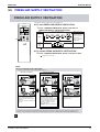
HUMID HEAT Operation
Operation
1. Select HEAT mode.
2. Set humidity.
2
1
(R9409)
∗ Refer to the operation manual for details.
Features
A world first new humidifying method has adopted
What is new in this method is to intake vapor in the outdoor air with the hygroscopic element
mounted in outdoor unit, and send indoors. This has enabled powerful and speedy
humidification apart from other company's methods which just absorb moisture in the indoor
air.
by taking in outdoor moisture
fully humidifying the room
by taking in outdoor
moisture
fully
humidifying the room
(R9410)
The room is uniformly humidified.
• Humidifier + heating operation by air conditioner
Moisture gathers around the ceiling, as it is lighter than the air even if the humidifier is
operated. The air on the floor is kept dry.
80
70
60
50
40
30
20
When using humidifier, moisture gathers around the ceiling.
(R3325)
Function and Control
9
Main Functions
SiBE12-908
• HUMID HEAT operation by URURU
This air conditioner enables uniformly humidifying the room by circulating vapor with warm
air.
80
70
60
50
40
30
20
The room is uniformly humidified.
(R3326)
Powerful humidifying ability
The humidifying capacity is 450 ml/h and equivalent to that of a normal humidifier.
The value is measured at 7°C DB / 6°C WB of outdoor air and with 4.0 m of humidifying hose
length.
No need for water supply nor cleaning
Water supply and cleaning are unnecessary as it does not have water tank, unlike
humidifiers, and there is no proliferations of bacteria.
Humidity control
The target of the humidity level is 40 to 50%RH.
You can select from Low, STD (standard), Hi (high), and CONT (continuous). The target
humidity (%) cannot be set.
Note
When the outdoor temperature and humidity are low, the humidifying capacity is decreased.
In addition, the moisture in the room may not attain sufficient humidity when the ventilation
volume is high, the preset temperature is high, or the preset humidity is HIGH.
After the “humid heating” operation starts, the relative humidity in the room lowers
temporarily. This phenomenon is caused by the increase of the saturation water vapor.
Therefore, the humidity raises gradually after the temperature reaches the preset
temperature.
In the humidifying operation, the operation sound increases by about 2 dB in the indoor unit
and 3 dB in the outdoor unit.
This system does not suppose the storage of musical instruments or the like.
Conditions for
Humidifying
Operation
Note
While heating mode, humidifying operation can be available when the following conditions 1~5
are met at the same time.
1. Indoor heat exchanger temperature is 12°C or more.
2. Outdoor temperature is from –10°C to 24°C (meanwhile, in test operation, up to 34°C is
possible). Humidifying operation does not work under –10°C.
3. Approx. 1 minute has already passed after heating operation startup. (See Note.)
4. Heating operation does not work to its full capacity. (Meanwhile, the “continuous”
humidification is selected, humidifying operation has the priority.)
5. Room humidity is under 70%RH.
Exclude the case when it is recovered from thermostat-off or when the defrosting operation
finished.
10
Function and Control
SiBE12-908
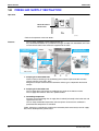
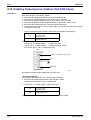
How to Check the
Motion of
Humidifying
Operation
Main Functions
You can check whether the humidifying unit is in good working order. If you set HUMID HEAT
test operation (refer to the installation manual for details), you can check even beyond the range
of the conditions for humidifying operation.
1. Hygroscopic fan .......................... Air is exhaled from the front exhaust outlet of outdoor unit.
2. Humidifying fan/heater/damper ... Warm air is blown from the duct of outdoor unit.
3. Humidification rotor ..................... The rotor is rotating with top panel off.
As for the performance, estimate from psychrometric chart with the measured temperature and
humidity of the outdoor air and of the humidified air (in front of the indoor outlet) using thermal
hygrometer.
Airflow rate (m3/min)
0.38
Humidity
Fluctuation by
Temperature
Settings
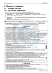
At HUMID HEAT operation, as room temperature rises, relative humidity is temporarily lowered.
This is because as room temperature rises, relative humidity is lowered even if the moisture
content is the same.
e.g.) The rise in the room temperature from 15°C to 25°C will result in the fall in humidity from
40%RH to about 22%RH.
As humidifying operation starts concurrently with heating, humidity rises gradually as shown in
the figure below.
Some room conditions (floor space, ventilation frequency, number of residents, etc.) and
temperature settings (mostly higher settings) may result in unsatisfactory humidity settings.
Humidity Fluctuation on HUMID HEAT Operation
Humidity
(%)
100
90
“HUMID HEAT” start
80
When room temperature rises,
relative humidity is lowered
even if the moisture
content is same.
70
60
Setting temp.
17
20
50
40
23
Humidity rises
gradually.
30
Heating
without humidifying
setting temp. 23
20
10
0
20
40
60
Measurement Conditions
Outdoor temp.: 7
HUMID HEAT operation setting:
Temp.; each setting as below, Humidity; “CONT” (Continuous)
Airflow rate setting: H tap
Area of the room: 26.4 m²
Humidifying hose length: 4.0 m
Ventilation: 0.75 times/hour
0.5 times of natural ventilation
0.25 times of humidity absorption by a carpet, a curtain, etc.
Function and Control
80
100
Time (min.)
(R9411)
11
Main Functions
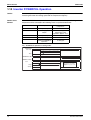
Time chart for
humidifying
operation control
SiBE12-908
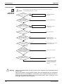
Approx. 1min. after HUMID HEAT operation start up, it repeats humidifying and drying
alternately (to protect condensation for inside the hose).
ON
HUMID HEAT
operation
OFF
Approx. 1min
Approx. 3min
Humidifying fan
and damper
ON
OFF
b'
a
b
a
b
a
b'
ON
Hygroscopic
fan
OFF
Heater
ON
Dry mode
OFF
15 sec.
15 sec.
ON
Rotor
OFF
(R9412)
. Humidifying time
Approx. 70min.
Decide time according to the outdoor temperature
and hose length set by remote controller.
. Drying time
’. Drying time
Approx. 2~10min.
Approx. 2~10min.
Decide time according to the hose length set by
remote controller.
Time chart for HUMID HEAT operation on trial mode
HUMID HEAT operation on trial mode works in the same sequence as HUMID HEAT
operation, but about 30 min. later it automatically stops.
Remark
When a room is spacious such as loft style or partitioned by accordion style curtain, the
ventilation volume is large and may not sometimes reach the set humidity.
12
Function and Control
SiBE12-908
Humidification
performance by
outdoor
temperature
Main Functions
The humidifying of this system is different from that of the normal humidifier. Therefore, the
humidifying performance varies with the outdoor temperature or installation condition.
Sufficient humidifying capacity may not be attained depending on the weather condition in
operation.
When the outdoor temperature lowers by 5°C, the humidifying capacity is decreased by about
15%.
When the outdoor humidity lowers by 20%, the humidifying capacity is decreased by about
20%.
Humidifying hose length : 4.0m
Humidifying Capacity (ml/h)
600
Outdoor relative humidity
87%RH
rated : 450ml/h
(Indoor 20ºCDB, Outdoor 7ºCDB/6ºCWB)
500
80%RH
70%RH
60%RH
50%RH
40%RH
400
300
30%RH
20%RH
200
100
0
0
2
4
6
8
10
Outdoor temperature (ºC)
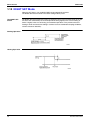
Performance
compensation by
hose length
(R9413)
The max. piping length is 15 m, but the longer the length of the humidifying hose becomes, the
less the humidifying performance becomes.
Outdoor temp. 7˚CDB, 6˚CWB
Humidifying Capacity Ratio
(Piping length = 4m nominal)
105.0%
100.0%
95.0%
90.0%
A
a
b
c
B
d
e
f
85.0%
80.0%
2
3
4
5
6
7
8
9
10
11
12
13
14
15
Hose length (m)
(R9414)
Applicable hose (Hose diameter)
A : KPMH996A10S (I.D.25mm)
B : KPMH996A15S (I.D.30mm)
Hose length setting
a : ~3.0m, b : 3.1~4.0m, c : 4.1~6.0m, d : 6.1~8.0m,
e : 8.1~10.0m, f : 10.1m~
Function and Control
13
Main Functions
1.8
SiBE12-908
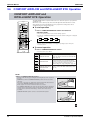
FRESH AIR SUPPLY VENTILATION
Operation
FRESH AIR SUPPLY
VENTILATION
(R9425)
∗ Refer to the operation manual for details.
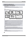
Features
The air supply ventilation system using only fresh air.
Any contaminated outdoor air is purified in two stages of indoor unit and outdoor unit. Fresh
air from which bacteria were removed is supplied into the room.
2. Pollen and dust are
removed.
Indoor
Indoor
Unit
Outdoor
1. Unpleasant odors
are decomposed.
Air Supply
Filter
Unpleasant
Odors,
Pollen
Thermal
Catalyst
3. Temperature
Control
Fresh Air
Fresh Air
Indoor Unit
Outdoor Unit
Odor
Pollen
Dust
(R9415)
1. Purifying air in the outdoor unit
Thermal catalyst containing in the humidifying rotor analyzes unpleasant odor and also
removes exhaust gases (NOX, SOX).
Manganese catalyst used to treat the automotive exhaust gas is adopted for the thermal
catalyst.
2. Purifying air in the indoor unit
The air supply filter is placed at the humidifying hose outlet of the indoor unit side.
The air supply filter removes about 97% pollen and dust.
3. Controlling temperature
The fresh air passed through the air supply filter is cooled (or heated) in the indoor unit and
supplied into the room.
You can keep comfortable temperature and also replace air because the ventilation is
performed while temperature is controlled.
Pollen, exhaust gas and odor that could not be removed by the thermal catalyst and air supply
filter will be decomposed by photocatalyst.
14
Function and Control
SiBE12-908
Main Functions
Ventilation System
The ventilation type is mainly divided into two. The convenient system is supply ventilation.
Supply Ventilation
Exhaust Ventilation
Fresh
Air
Air Supply Draft
(R5979)
Function and Control
- Quiet because the ventilation fan is located in
the outdoor unit
- Operation noise is heard because the ventilation
fan is located in the room.
- Energy saving system due to low heat loss
- Electricity charges are high because heat loss is
high.
- The room temperature changes little because
no wind enters
- Draft enters easily to prevent comfortable
temperature from being kept.
15
Main Functions
1.9
SiBE12-908
2-AREA INTELLIGENT EYE
The following functions can be performed by a human motion sensor (INTELLIGENT EYE).
1. Reduces the capacity when there is no human in the room in order to save electricity.
(energy saving operation)
2. Divides the room into plural areas and detects existence of humans in each area.
Shifts the airflow direction to the area having no human automatically to avoid direct airflow
on humans.
Processing
1. Detection method by INTELLIGENT EYE
sampling (20msec)
Sensor output
1sec
If the sensor detects the outputs 10 times/sec.
or more, it judges humans exist.
High
Low
(Condition of 10 times or more output)
Detection signal ON
from the sensor OFF
(Human motion)
(Continue 3 sec.)
If the detection signal (ON) continues 3 sec. or more,
it judges humans exist.
Human detection ON
signal
OFF
(R2821)
This sensor detects human motion by receiving infrared rays and displays the pulse wave
output.
A microcomputer in an indoor unit carries out a sampling every 20 msec. and if it detects 10
cycles of the wave in one second in total (corresponding to 20msec.× 10 = 200msec.), and
when the ON signal continues 3 sec., it judges human is in the room as the motion signal is
ON
INTELLIGENT EYE sensor is divided into 2 areas and detects humans in each area.
Image of 2-AREA INTELLIGENT EYE
Wall
Indoor unit
Area B
Top view
Area A
· A microcomputer judges human existence in
area A and B by the sensor signal from each
(R3854)
16
Function and Control
SiBE12-908
Main Functions
2. The motions in energy saving operation (for example: in cooling)
within 20
minutes.
Human detection ON
signal
OFF
(From area A or B)
20 min.
20 min.
RESET.
Cooling : Set temp. + 2˚C
Heating : Set temp. - 2˚C
Set temp.
INTELLIGENT EYE ON
LED
OFF
Remote controller
INTELLIGENT EYE ON
button
OFF
Operation
ON
OFF
Fan speed ( 1)
Set speed
Set speed
Set speed - 60 rpm
OFF
(R8350)
When a microcomputer doesn’t have a signal from the sensor in 20 minutes, it judges that
nobody is in the room and operates the unit in temperature shifted 2°C from the set
temperature. (Cooling/Dry : 2°C higher, Heating : 2°C lower and AUTO : according to the
operation mode at that time.)
1
★ In case of FAN mode, the fan speed reduces by 60 rpm.
3. Airflow direction in 2-AREA INTELLIGENT EYE operation
Detection method: The opposite area of detected area is set as the target direction.
Wall
Top view
Indoor unit
Left
Right
Human
Area B
1.
2.
3.
4.
Area A
(R3853)
Detection signal ON in both area A and B: Shift the airflow direction to area B (left side)
Detection signal ON in area A: Shift the airflow direction to area B (left side)
Detection signal ON in area B: Shift the airflow direction to area A (right side)
Detection signal OFF in both area A and B: No change
* When the detection signal OFF in both area A and B, the unit starts energy saving operation.
Others
The dry operation can not command the setting temperature with a remote controller, but
internally the set temperature is shifted by 1°C.
Function and Control
17
Main Functions
SiBE12-908
1.10 Inverter POWERFUL Operation
Outline
In order to exploit the cooling and heating capacity to full extent, operate the air conditioner by
increasing the indoor fan rotating speed and the compressor frequency.
Details of the
Control
When POWERFUL button is pushed in each operation mode, the fan speed / setting
temperature will be converted to the following states in a period of 20 minutes.
Operation mode
Fan speed
COOL
H tap + 50 rpm
DRY
Dry rotating speed +
50 rpm
HEAT
H tap + 50 rpm
FAN
AUTO
H tap + 50 rpm
Same as cooling /
heating in POWERFUL
operation
Remote controller set
temperature
18°C
Normally targeted
temperature in dry
operation; Approx. –2°C
30°C
—
The target is kept
unchanged
Ex.) : POWERFUL operation in cooling mode.
Target temp.
Set temp.
It should be the lower limit of cooling temperature.
18˚C
POWERFUL ON
It counts 20 min. also in the remote controller.
POWERFUL OFF
Fan
50rpm
H tap
20min.
Ending condition: "or" in 1 to 3
1. After the lapse of 20 minutes.
2. Stop
3. POWERFUL operation is OFF.
Set tap
(R4606)
18
Function and Control
SiBE12-908
Main Functions
1.11 ECONO Mode
Outline
The "ECONO mode" reduces the maximum operating current and power consumption by
approx. 30% during start up etc..
This mode is particularly convenient for energy-saving-oriented users. It is also a major bonus
for those whose breaker capacities do not allow the use of multiple electrical devices and air
conditioners.
It is easily activated from the wireless remote controller by pushing the ECONO button.
When this function is ON, the maximum capacity is also down. (Approx. 20%)
This function can only be set when the unit is running. Pressing the operation stop button
causes the settings to be canceled.
This function and POWERFUL operation cannot be used at the same time. The latest
command has the priority.
Power
consumption
and current
Normal
Econo Mode
Time
(R4300)
Details
ECONO mode can be activated while the unit is running. The remote controller can send the
ECONO command when the unit is in COOL, HEAT, DRY, or AUTO operation.
When the ECONO command is valid, the input current is under reducing control.
(Refer to "Input current control" on page 33.)
Function and Control
19
Main Functions
SiBE12-908
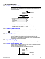
1.12 NIGHT SET Mode
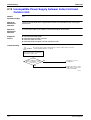
When the OFF timer is set, the NIGHT SET circuit automatically activates.
The NIGHT SET circuit maintains the airflow setting made by users.
The NIGHT SET
Circuit
The NIGHT SET circuit continues heating or cooling the room at the set temperature for the first
one hour, then automatically raises the temperature setting slightly in the case of cooling, or
lowers it slightly in the case of heating, for economical operations. This prevents excessive
heating in winter and excessive cooling in summer to ensure comfortable sleeping conditions,
and also conserves electricity.
Cooling Operation
Heating Operation
20
Function and Control
SiBE12-908
Main Functions
1.13 Other Functions
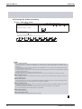
1.13.1 Multi-Colored Indicator Lamp
Features
Current operation mode is displayed in color of the lamp of the indoor unit which changes in 6
colors. Operating status can be monitored even in automatic operation in accordance with the
content of actual operation.
Multi-colored
indicator lamp
(R9426)
z The lamp color changes according to the operation.
z Heating......................................................Red
z HUMID HEAT............................................Orange
z Cooling......................................................Blue
z DRY ..........................................................Green
z FAN...........................................................White
z The lamp color also changes according to the optional function.
z FRESH AIR SUPPLY VENTILATION .......White
(Only for the first 2 seconds during operation of the air conditioner.)
z Standby state (ex. mode conflict)..............Yellow
1.13.2 WEEKLY TIMER Operation
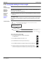
Up to 4 timer settings can be saved for each day of the week (up to 28 settings in total).
Those 3 items of “ON / OFF”, “temperature” and “time” can be set.
Refer to “WEEKLY TIMER Operation” on page 86 for detail.
1.13.3 Hot Start Function
In order to prevent the cold air blast that normally comes when heating is started, the
temperature of the heat exchanger of the indoor unit is detected, and either the airflow is
stopped or is made very weak thereby carrying out comfortable heating of the room.
*The cold air blast is also prevented using a similar control when the defrosting operation is
started or when the thermostat gets turned ON.
1.13.4 Signal Receiving Sign
When the indoor unit receives a signal from the remote controller, the unit emits a signal
receiving sound.
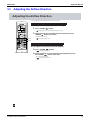
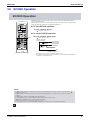
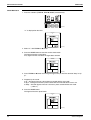
1.13.5 ON/OFF Button on Indoor Unit
An ON/OFF button is provided on the front panel of the unit. Use this button when the remote
controller is missing or if its battery has run out.
Every press of the button switches from ON to OFF or from OFF to ON.
ON/OFF button
(R9408)
Function and Control
21
Main Functions
SiBE12-908
Push this button once to start operation. Push once again to stop it.
This button is useful when the remote controller is missing.
The operation mode refers to the following table.
Heat Pump
Mode
Temperature setting
Airflow rate
AUTO
25°C
AUTO
In the case of multi system operation, there are times when the unit does not activate with
this button.
<Forced operation mode>
Forced operation mode will be set by pressing the ON/OFF button for between 5 to 9 sec. while
the unit is not operating.
See page 42 for the detail of "Forced Operation Mode".
Note:
When the ON/OFF button is pressed for 10 sec. or more, the operation will be stopped.
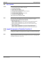
1.13.6 Titanium Apatite Photocatalytic Air-Purifying Filter
This filter combines the Air Purifying Filter and Titanium Apatite Photocatalytic Deodorizing
Filter in a single highly effective unit. The filter traps microscopic particles, decompose odours
and even deactivates bacteria and viruses. It lasts for 3 years without replacement if washed
about once every 6 months.
1.13.7 Air Filter (Prefilter)
The air filter net is impregnated with a safe, odorless mold preventative to make the filter
virtually immune to mold.
1.13.8 Auto-restart Function
Even if a power failure (including one for just a moment) occurs during the operation, the
operation restarts in the condition before power failure automatically when power is restored.
(Note) It takes 3 minutes to restart the operation because the 3-minute standby function is
activated.
22
Function and Control
SiBE12-908
Main Functions
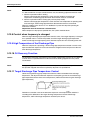
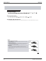
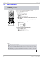
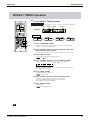
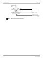
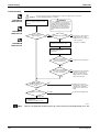
1.14 Table for Special Modes
Indoor [ON/OFF] 5~9 sec.
[CANCEL] 5 sec.
A
Forced operation mode
B
Easy diagnosis mode
• Indoor [ON/OFF]
• Left for 15 min.
• [CANCEL] 5 sec.
• Left for 60 sec.
Mode selection view:
Select with TEMP
or
button.
5C
Service check mode
2
T
Trial operation mode
3
P5
Pipe set mode
1
Left for 60 sec.
[MODE]
Diagnosis
• [MODE] 5 sec.
• Left for 60 sec.
[MODE]
Trial operation ON
• Operation OFF
• Left for 30 min.
[MODE]
Hose length setting
Normal mode
Normal mode
[MODE]
+
TEMP
+
TEMP
[MODE] 2 sec.
4
PC
5
[MODE]
Pipe check mode
Hose length check
• [MODE] 5 sec.
• Left for 60 sec.
[MODE] Hose Dry
operation ON
• [MODE] 5 sec.
Drying mode
• [MODE] 5 sec.
• Left for 30 min.
6
H
Humiditying airflow
rate setting mode
[MODE] Airflow rate
setting
7
L
Monitor brightness
setting mode
[MODE] Monitor brightness • [MODE] 5 sec.
setting
• Left for 60 sec.
• Left for 60 sec.
(R9416)
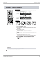
A. Forced operation mode:
The buzzer beeps, and the timer and multi-colored indicator lamp illuminate.
Refer to page 42 for detail.
B. Easy diagnosis mode:
You can identify the error code in a quite simple way but some of the error codes do not appear
on the LCD.
Refer to the Check Method 1 on page 97 for detail.
1. Service check mode:
You can identify the error code for diagnosis.
Refer to the Check Method 2 on page 98 for detail.
Function and Control
23
Main Functions
SiBE12-908
2. Trial operation mode:
You can select a mode for trial operation on the remote controller.
The operation continues for approx. 30 minutes.
Refer to the installation manual on page 57 for detail.
3. Pipe set mode:
You can set the humidifying hose length and then check the preset value.
Refer to the installation manual on page 56 for detail.
4. Pipe check mode:
You can check the preset value of the humidifying hose length.
Refer to the installation manual on page 56 for detail.
5. Drying mode:
Hose Dry operation is a forced drying operation for humidifying hose.
The operation continues for approx. 30 minutes.
Cooling, heating, or dry operation is not available during Hose Dry operation.
Refer to the installation manual on page 57 for detail.
6. Humidifying airflow rate setting mode:
Humidifying airflow rate setting mode allows to fine-tune the speed of the humidifying fan
around ±10% relative to Automatic. Set high to increase the airflow rate, or set to low to
decrease.
7. Monitor brightness setting mode:
The brightness of the multi-colored indicator lamp can be adjusted H (high), L (low), or OFF.
24
Function and Control
SiBE12-908
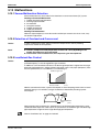
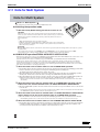
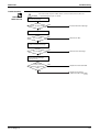
Function of Thermistor
2. Function of Thermistor
2.1
Heat Pump Model
Expansion valve
E
EVA
EVB
A
Four way valve
D
B
C
Compressor
(R7042)
A Outdoor Heat
Exchanger
Thermistor
1. The outdoor heat exchanger thermistor is used for controlling target discharge temperature.
The system sets a target discharge temperature according to the outdoor and indoor heat
exchanger temperature, and controls the electronic expansion valve opening so that the
target discharge temperature can be obtained.
2. The outdoor heat exchanger thermistor is used for detecting disconnection of the discharge
thermistor when cooling.
When the discharge pipe temperature becomes lower than the outdoor heat exchanger
temperature, the discharge pipe thermistor is judged as disconnected.
3. The outdoor heat exchanger thermistor is used for high pressure protection during cooling
operation.
B Discharge
Pipe Thermistor
1. The discharge pipe thermistor is used for controlling temperature of the discharge pipe.
If the temperature of discharge pipe (used in place of the inner temperature of the
compressor) rises abnormally, the operating frequency drops or the operation halts.
2. The discharge pipe thermistor is used for detecting disconnection of the discharge
thermistor.
C Gas Pipe
Thermistor
1. In cooling, the gas pipe thermistors are used for gas pipe isothermal control.
The system controls electronic expansion valve opening so that gas pipe temperature in
each room becomes equal.
Function and Control
25
Function of Thermistor
SiBE12-908
D Indoor Heat
Exchanger
Thermistor
1. The indoor heat exchanger thermistors are used for controlling target discharge temperature.
The system sets a target discharge pipe temperature according to the outdoor and indoor
heat exchanger temperature, and controls the electronic expansion valve opening so that
the target discharge temperature can be obtained.
2. The indoor heat exchanger thermistor is used to prevent freezing.
During the cooling operation, if the temperature drops abnormally, the operating frequency
becomes lower, then the operation halts.
3. The indoor heat exchanger thermistor is used for anti-icing control.
During the cooling operation, if the heat exchanger temperature in the room where operation
is halted becomes -1°C, or if the room temperature - heat exchanger temperature in the
room where operation is halted becomes ≥10°C, it is assumed as icing.
4. The indoor heat exchanger thermistor is used to heating peak-cut control.
During heating operation, if the temperature rises abnormally, the operating frequency
becomes lower, then the operation halts.
5. During heating: the indoor heat exchanger thermistors are used for detecting disconnection
of the discharge pipe thermistor.
When the discharge pipe temperature become lower than an indoor heat exchanger
temperature, a disconnected discharge pipe thermistor can be detected.
The indoor heat exchanger thermistors are also used for preventing abnormal high pressure.
6. When only one indoor unit is operating, the indoor heat exchanger thermistor is used for
sub-cooling control.
The actual sub-cooling is calculated from the liquid pipe temperature and the heat
exchanger temperature. The system controls the electronic expansion valve opening to
reach the target sub-cooling.
E Liquid Pipe
Thermistor
1. When only one indoor unit is heating, the indoor liquid pipe thermistor is used for a subcooling control.
The system calculates the actual sub-cooling with the liquid pipe temperature and the
maximum heat exchanger temperature between rooms, and controls the opening of the
electronic expansion valve to reach the target sub-cooling.
2. When all indoor units are heating, the liquid pipe thermistor is used for liquid pipes
isothermal control.
The system controls electronic expansion valves to make liquid pipe temperatures the
average of present temperature of each room.
26
Function and Control
SiBE12-908
Control Specification
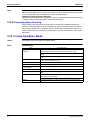
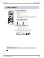
3. Control Specification
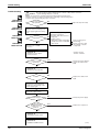
3.1
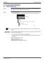
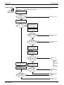
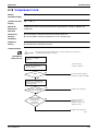
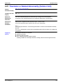
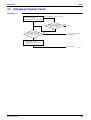
Mode Hierarchy
Outline
There are two modes; the mode selected in user’s place (normal air conditioning mode) and
forced operation mode for installation and providing service.
Detail
1. For heat pump model
There are following modes; stop, cooling (includes drying), heating (include defrosting)
Air conditioner control mode
Forced operating mode
Forced cooling (for Pump Down Operation)
Normal operating mode
Cooling
Heating
Defrosting
Stop mode (except for cooling/heating modes by indoor command)
Preheat operation
During C (capacitor) is discharging
Stop
(R2829)
Note:
Decision of the
operation mode
Unless specified otherwise, an indoor dry operation command must be regarded as cooling
operation.
In this multi system, when both 2 indoor units are operating, one of them may enter the standby
mode by the following conditions.
The units in the 2 rooms are different in operation mode
The indoor units in both 2 rooms are set to HUMID HEAT operation or FRESH AIR SUPPLY
VENTILATION
Refer to the following pages for detail.
“Note for multi” on page 91.
“HUMID HEAT operation” on page 77.
“FRESH AIR SUPPLY VENTILATION” on page 79.
Function and Control
27
Control Specification
3.2
SiBE12-908
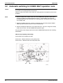
Automatic switching for HUMID HEAT operation room
Outline
When the indoor units in both 2 rooms are set to HUMID HEAT operation, priority will be given
to the indoor unit starting operation first basically.
However, priority will be given to the indoor unit starting operation subsequently under certain
conditions.
Detail
1. When the indoor units in both 2 rooms are set to HUMID HEAT operation, priority will be
given to the indoor unit starting operation first (Unit 1), and the indoor unit will go into
humidifying operation while the indoor unit starting operation subsequently (Unit 2) will go
into standby mode.
2. When the humidity of the Unit 1 reaches a target level, the unit which performs HUMID
HEAT operation switches from Unit 1 to Unit 2 automatically.
3. When the temperature decreases in the room of the Unit 1, the Unit 2 will go into standby
mode, then, the Unit 1 will start HUMID HEAT operation again.
Carry out priority room setting to prevent the room of HUMID HEAT operation from switching
automatically.
How to carry out priority room setting
Cut the jumper of the outdoor unit PCB.
Cut the JP9 → Room-A will be set as the priority room.
Cut the JP10 → Room-B will be set as the priority room.
JP9
JP10
(R9428)
28
Function and Control
SiBE12-908
3.3
Control Specification
Frequency Control
Outline
Frequency that corresponds to each room’s capacity will be determined according to the
difference in the temperature of each room and the temperature that is set by the remote
controller.
The function is explained as follows.
1. How to determine frequency.
2. Frequency command from an indoor unit. (The difference between a room temperature and
the temperature set by the remote controller.)
3. Frequency command from an indoor unit. (The ranked capacity of the operating room).
4. Frequency initial setting.
5. PI control.
Frequency changes by PI control < repeats when frequency becomes lower
Command frequency X repeats when frequency becomes lower
Each drooping function
Input current control, etc.
Upper limit frequency
FMAX
Command frequency
Limit frequency
Initial frequency
PI control
Defrost control (*)
Lower limit frequency
FMIN
Each upper limit function
Compressor protection function
Skip control
Target frequency
Each lower limit function
Four-way valve operating compensation, etc. (*)
*; only for heat pump model
(R1375)
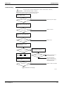
Detail
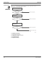
How to Determine Frequency
The compressor frequency will finally be determined by taking the following steps.
For Heat Pump Model
1. Determine command frequency
Command frequency will be determined in the following order of priority.
1.1 Limiting frequency by drooping function
Input current, discharge pipes, low Hz high pressure limit, peak cutting, freeze prevention,
dew prevention, fin thermistor temperature.
1.2 Limiting defrost control time
1.3 Forced cooling
1.4 Indoor frequency command
2. Determine upper limit frequency
Set a minimum value as an upper limit frequency among the frequency upper limits of the
following functions:
Compressor protection, input current, discharge pipes, Low Hz high pressure, peak cutting,
freeze prevention, defrost.
3. Determine lower limit frequency
Set a maximum value as an lower limit frequency among the frequency lower limits of the
following functions:
Four way valve operating compensation, draft prevention, pressure difference upkeep.
4. Determine prohibited frequency
There is a certain prohibited frequency such as a power supply frequency.
Function and Control
29
Control Specification
SiBE12-908
Indoor Frequency Command (∆D signal)
The difference between a room temperature and the temperature set by the remote controller
will be taken as the “∆D signal” and is used for frequency command.
Temperature
difference
∆D
signal
Temperature
difference
∆D
signal
Temperature
difference
∆D
signal
Temperature
difference
∆D
signal
0
2.0
4
4.0
8
6.0
C
0.5
∗Th
OFF
1
2.5
5
4.5
9
6.5
D
1.0
1.5
2
3
3.0
3.5
6
7
5.0
5.5
A
B
7.0
7.5
E
F
∗Th OFF = Thermostat OFF
Indoor Unit Capacity (S value)
The capacity of the indoor unit is a “S” value and is used for frequency command.
ex.)
Capacity
S value
2.5 kW
3.5 kW
25
35
Frequency Initial Setting
< Outline >
When starting the compressor, or when conditions are varied due to the change of the operating
room, the frequency must be initialized according to the total of a maximum ∆D value of each
room and a total value of Q (ΣQ) of the operating room (the room in which the thermostat is set
to ON).
Q value: Indoor unit output determined from indoor unit volume, airflow rate and other factors.
PI Control (Determine Frequency Up/Down by ∆D Signal)
1. P control
Calculate a total of the ∆D value in each sampling time (20 seconds), and adjust the
frequency according to its difference from the frequency previously calculated.
2. I control
If the operating frequency is not change more than a certain fixed time, adjust the frequency
up and down according to the Σ∆D value, obtaining the fixed Σ∆D value.
When the Σ∆D value is small...lower the frequency.
When the Σ∆D value is large...increase the frequency.
3. Limit of frequency variation width
When the difference between input current and input current drooping value is less than 1 A,
the frequency increase width must be limited.
4. Frequency management when other controls are functioning
When each frequency is drooping;
Frequency management is carried out only when the frequency droops.
For limiting lower limit
Frequency management is carried out only when the frequency rises.
5. Upper and lower limit of frequency by PI control
The frequency upper and lower limits are set depending on the total of S values of operating
room. When low noise commands come from the indoor unit more than one room or when
outdoor unit low noise or quiet commands come from all the rooms, the upper limit frequency
must be lowered than the usual setting.
30
Function and Control
SiBE12-908
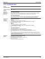
3.4
Control Specification
Controls at Mode Changing / Start-up
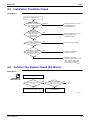
3.4.1 Preheating Operation
Outline
Operate the inverter in the open phase operation with the conditions including the preheating
command from the indoor, the outdoor air temperature and discharge pipe temperature.
Detail
Preheating ON Condition
When outdoor air temperature is below 10.5ºC and discharge pipe temperature is below
10.5ºC, inverter in open phase operation starts. (The power consumption of compressor
during preheating operation is 35 W.)
OFF Condition
When outdoor air temperature is higher than 12ºC or discharge pipe temperature is higher
than 12ºC, inverter in open phase operation stops.
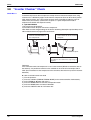
3.4.2 Four Way Valve Switching
Outline
During the heating operation current must be conducted and during cooling and defrosting
current must not be conducted. In order to eliminate the switching sound (as the four way valve
coil switches from ON to OFF) when the heating is stopped, the delay switch of the four way
valve must be carried out after the operation stopped.
Detail
The OFF delay of four way valve
Energize the coil for 150 sec after unit operation is stopped.
3.4.3 Four Way Valve Operation Compensation
Outline
At the beginning of the operation as the four way valve is switched, acquire the differential
pressure required for activating the four way valve by having output the operating frequency,
which is more than a certain fixed frequency, for a certain fixed time.
Detail
Staring Conditions
1. When starting compressor for heating.
2. When the operating mode changes from the previous time.
3. When starting compressor for starting defrosting or resetting.
4. When starting compressor for the first time after the reset with the power is ON.
5. When starting compressor after operation stop by the cooling / heating mode change-over
malfunction.
Set the lower limit frequency to
Hz for 60 seconds with any conditions with 1 through 5
above.
Cooling
40 class
56Hz
50 class
40Hz
Heating
68Hz
54Hz
3.4.4 3-Minute Standby
Prohibit to turn ON the compressor for 3 minutes after turning it off.
(Except when defrosting. )
Function and Control
31
Control Specification
SiBE12-908
3.4.5 Compressor Protection Function
When turning the compressor from OFF to ON, the upper limit of frequency must be set as
follows. (The function must not be used when defrosting.)
FCG 1
32
40 class 50 class
62
55
FCG 2
FCG 3
72
90
70
85
TCG 1
TCG 2
140
180
150
180
TCG 3
300
300
Function and Control
SiBE12-908
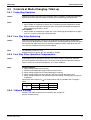
3.5
Control Specification
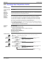
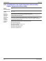
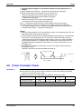
Discharge Pipe Temperature Control
Outline
The discharge pipe temperature is used as the compressor's internal temperature. If the
discharge pipe temperature rises above a certain level, the operating frequency upper limit is
set to keep this temperature from going up further.
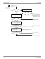
Detail
Divide the Zone
A
B
A
B
C
D
C
Keep
D
110
103
102
101
(R2836)
Management within the Zones
Zone
Stop zone
Drooping zone
Keep zone
Return / Reset zone
3.6
Control contents
When the temperature reaches the stop zone, stop the compressor and
correct abnormality.
Start the timer, and the frequency will be drooping.
Keep the upper limit of frequency.
Cancel the upper limit of frequency.
Input Current Control
Outline
Detect an input current by the CT during the compressor is running, and set the frequency
upper limit from such input current.
In case of heat pump model, this control is the upper limit control function of the frequency
which takes priority of the lower limit of four way valve activating compensation.
Detail
The frequency control will be made within the following zones.
When a “stop current” continues for 2.5 seconds after rushing on the stop zone, the compressor
operation stops.
If a “drooping current” is continues for 1.0 second after rushing on the drooping zone, the
frequency will be 2 Hz drooping.
Repeating the above drooping continues until the current rushes on the drooping zone without
change.
In the keep zone, the frequency limit will remain.
In the return / reset zone, the frequency limit will be cancelled.
Limitation of current drooping and stop value according to the outdoor air temperature
1. In case the operation mode is cooling
The current droops when outdoor air temperature becomes higher than a certain level
(model by model).
2. In case the operation mode is heating (only for heat pump model)
The current droops when outdoor air temperature becomes higher than a certain level
(model by model).
Function and Control
33
Control Specification
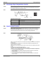
3.7
SiBE12-908
Freeze-up Protection Control
Outline
During cooling operation, the signals being sent from the indoor unit allow the operating
frequency limitation and then prevent freezing of the indoor heat exchanger. (The signal from
the indoor unit must be divided into the zones as the followings.
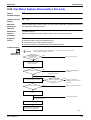
Detail
Conditions for Start Controlling
Judge the controlling start with the indoor heat exchanger temperature after 2 sec from
operation start and after 30 sec from changing number of operation room.
Control in Each Zone
(Reference)
Heat exchanger
thermistor temperature
Return from stop
13˚C
Reset zone
7˚C
Up zone
5˚C
Keep zone
3˚C
0˚C
Drooping zone
Stop zone
(R4561)
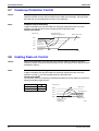
3.8
Heating Peak-cut Control
Outline
During heating operation, the signals being sent from the indoor unit allow the operating
frequency limitation and prevent abnormal high pressure. (The signal from the indoor unit must
be divided as follows.)
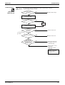
Detail
Conditions for Start Controlling
Judge the controlling start with the indoor heat exchanger temperature after 2 min from
operation start and
sec from changing number of operation room.
Control in Each Zone
The maximum value of heat exchange intermediate temperature of each indoor unit controls the
following (excluding stopped rooms).
(Reference)
When increase
When decrease
30
2
Stop zone
65˚C
55˚C
Drooping zone
Keep zone
54˚C
52˚C
Up zone
50˚C
Heat exchanger
thermistor
temperature
34
Reset zone
(R9851)
Function and Control
SiBE12-908
3.9
Control Specification
Fan Control
Outline
Fan control is carried out according to the following conditions.
1. Fan ON control for electric component cooling fan
2. Fan control when defrosting
3. Fan OFF delay when stopped
4. ON/OFF control when cooling operation
5. Fan control when the number of heating rooms decreases
6. Fan control when forced operation
7. Fan control in indoor / outdoor unit quiet operation
8. Fan control during heating operation
9. Fan control in the POWERFUL mode
10.Fan control for pressure difference upkeep
Detail
Fan OFF Control when Stopped
Fan OFF delay for 60 seconds must be made when the compressor is stopped.
Tap Control in Indoor / Outdoor Unit Quiet Operation
1. When Cooling Operation
When the outdoor air temperature is higher than 37°C, the fan tap must be set to H.
When the outdoor air temperature is 18 ~ 37°C, the fan tap must be set to M.
When the outdoor air temperature is lower than 18°C, the fan tap must be set to L.
2. When Heating Operation
When the outdoor air temperature is lower than 4°C, the fan tap must be set to H.
When the outdoor air temperature is 4 ~ 12°C, the fan tap must be set to M.
When the outdoor air temperature is higher than 12°C, the fan tap must be set to L.
3.10 Liquid Compression Protection Function 2
Outline
In order to obtain the dependability of the compressor, the compressor must be stopped
according to the conditions of the temperature of the outdoor air and outdoor heat exchanger.
Detail
Operation stops depending on the outdoor air temperature.
Compressor operation turns OFF under the conditions that the system is in cooling operation
and outdoor air temperature is below 10°C.
Function and Control
35
Control Specification
SiBE12-908
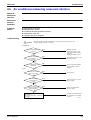
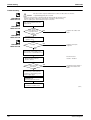
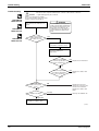
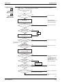
3.11 Defrost Control
Outline
Defrosting is carried out by the cooling cycle (reverse cycle). The defrosting time or outdoor
heat exchanger temperature must be more than its fixed value when finishing.
Detail
Conditions for Starting Defrost
The starting conditions must be made with the outdoor air temperature and heat exchanger
temperature. Under the conditions that the system is in heating operation, 6 minutes after the
compressor is started and more than 30 minutes of accumulated fine pass since the start of the
operation or ending the defrosting.
Conditions for Canceling Defrost
The judgment must be made with heat exchanger temperature. (40 class : 4°C~12°C, 50 class :
4°C~15°C)
Frequency
PI control
0 Hz
60 sec.
Compressor
120 sec.
530 sec.
30 sec.
ON
OFF
Four way valve
ON
OFF
5 sec.
5 sec.
Fan
ON
OFF
120 sec.
Operating room
electronic expansion
valve opening
Operation stopped room
electronic expansion
valve opening
450 pulse 40 class: 350 pulse
50 class: 300 pulse
140 pulse
350 pulse
40 class: 160 pulse
50 class: 200 pulse
450 pulse
Initial opening
0 pulse
Initial opening
(R7163)
36
Function and Control
SiBE12-908
Control Specification
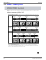
3.12 Electronic Expansion Valve Control
Outline
The following items are included in the electronic expansion valve control.
Electronic expansion valve is fully closed
1. Electronic expansion valve is fully closed when turning on the power.
2. Pressure equalizing control
Room Distribution Control
1. Gas pipe isothermal control
Liquid pipe temperature control (with all ports connected and all rooms being airconditioned)
2. SC control
Open Control
1. Electronic expansion valve control when starting operation
2. Control when frequency changed
3. Control for defrosting
4. Oil recover control
5. Control when a discharge pipe temperature is abnormally high
6. Control when the discharge pipe thermistor is disconnected
7. Control for indoor unit freeze-up protection
Feedback Control
1. Discharge pipe temperature control
Function and Control
37
Control Specification
SC control
Control when frequency changed
Control for abnormally high discharge
pipe temperature
Oil recovery control
Indoor freeze prevention control
Liquid pipe temperature control
Dew buildup prevention control for
indoor rotor
The followings are the examples of control which function in each mode by the electronic
expansion valve control.
Gas pipe isothermal control
Detail
SiBE12-908
Fully closed when power is turned ON
×
×
×
×
×
×
×
×
Open control when starting
×
×
×
{
×
{
×
{
(Control of target discharge pipe temperature)
×
×
{
{
{
{
×
{
Control when the operating room is changed
×
×
×
{
×
{
×
{
(Control of target discharge pipe temperature)
{
×
{
{
×
{
×
{
Pressure equalizing control
×
×
×
×
×
×
×
×
Open control when starting
×
×
×
{
×
×
×
×
(Control of target discharge pipe temperature)
×
{
{
{
×
×
×
×
Control when the operating room is changed
×
×
×
{
×
×
×
×
(Control of target discharge pipe temperature)
×
×
{
{
×
×
{
×
(Defrost control FD=1)
×
×
×
×
×
×
×
×
Pressure equalizing control
×
×
×
×
×
×
×
×
Open control when starting
×
×
×
{
×
×
×
×
Control of discharge pipe
thermistor disconnection
Continue
×
{
{
×
×
×
{
×
Stop
Pressure equalizing control
×
×
×
×
×
×
×
×
Operation pattern
{ : function
× : not function
When power is turned ON
Cooling, 1 room operation
Cooling, 2 rooms operation
Stop
Heating, 1 room operation
Heating, 2 rooms operation
Stop
Heating, 1 room operation
(R9427)
38
Function and Control
SiBE12-908
Control Specification
3.12.1 Fully Closing with Power On
Initialize the electronic expansion valve when turning on the power, set the opening position and
develop pressure equalizing.
3.12.2 Pressure Equalization Control
When the compressor is stopped, open and close the electronic expansion valve and develop
pressure equalization.
3.12.3 Opening Limit
Outline
Limit a maximum and minimum opening of the electronic expansion valve in the operating room.
Detail
A maximum electronic expansion valve opening in the operating room : 450 pulses
A minimum electronic expansion valve opening in the operating room : 60 pulses
The electronic expansion valve is fully closed in the room where cooling is stopped and is
opened with fixed opening during defrosting.
3.12.4 Gas Pipe Isothermal Control During Cooling
When the units are operating in multiple rooms, detect the gas piping temperature and correct
the electronic expansion valve opening so that the temperature of the gas pipe in each room
becomes identical.
When the gas pipe temperature > the average gas pipe temperature → open the electronic
expansion valve in that room
When the gas pipe temperature < the average gas pipe temperature → close the electronic
expansion valve in that room
3.12.5 SC Control
Outline
Detect the temperature of liquid pipe and heat exchanger of the rooms and compensate the
electronic expansion valve opening so that the SC of each room becomes the target SC.
When the actual SC is > target SC, open the electronic expansion valve of the room.
When the actual SC is < target SC, close the electronic expansion valve of the room.
Detail
Start Functioning Conditions
After finishing the open control (630 seconds after the beginning of the operation), control all the
electronic expansion valve in the operating room.
Determine Electronic Expansion Valve Opening
Adjust the electronic expansion valve so that the temperature difference between the maximum
heat exchanger temperature of connected room and the temperature of liquid pipe thermistor
becomes constant.
3.12.6 Starting Operation / Changing Operating Room Control
Control the electronic expansion valve opening when the system is starting or the operating
room is changed, and prevent the system to be super heated or moistened.
3.12.7 Disconnection of the Discharge Pipe Thermistor
Outline
Function and Control
Detect a disconnected discharge pipe thermistor by comparing the discharge pipe temperature
with the condensation temperature. If any is disconnected, open the electronic expansion valve
according to the outdoor air temperature and the operating frequency, and operate for a
specified time, and then stop.
After 3 minutes of waiting, restart the unit and check if any is disconnected. If any is
disconnected stop the system after operating for a specified time. If the disconnection is
detected 4 times in succession, then the system will be down.
39
Control Specification
Detail
SiBE12-908
Detect Disconnection
If a 780-second timer for open control becomes over, the following adjustment must be made.
1. When the operation mode is cooling
When the discharge pipe temperature is lower than the outdoor heat exchanger
temperature, the discharge pipe thermistor disconnection must be ascertained.
2. When the operation mode is heating (only for heat pump model)
When the discharge pipe temperature is lower than the max temperature of operating room
heat exchanger, the discharge pipe thermistor disconnection must be ascertained.
When the condition of the above 1 or 2 is decided, the system will stop after operating for
continuous 9 minutes.
Adjustment when the thermistor is disconnected
When compressor stop repeats specified time, the system should be down.
3.12.8 Control when frequency is changed
When the target discharge pipe temperature control is active, if the target frequency is changed
for a specified value in a certain time period, cancel the target discharge pipe temperature
control and change the target opening of the electronic expansion valve according to the shift.
3.12.9 High Temperature of the Discharge Pipe
When the compressor is operating, if the discharge pipe temperature exceeds a certain value,
open the electronic expansion valve and remove the refrigerant to the low pressure side and
lower discharge temperature.
3.12.10 Oil Recovery Function
Outline
The electronic expansion valve opening in the cooling stopped room must be set as to open for
a certain time at a specified interval so that the oil in the cooling stopped room may not be
accumulated.
Detail
During cooling operation, every 1 hour continuous operation, the electronic expansion valves in
the operation stopped room must be opened by 80 pulses for specified time.
3.12.11 Target Discharge Pipe Temperature Control
Obtain the target discharge pipe temperature from the indoor and outdoor heat exchange
temperature, and adjust the electronic expansion valve opening so that the actual discharge
pipe temperature become close to that temperature. (Indirect SH control using the discharge
pipe temperature)
Determine a correction value of the electronic expansion valve compensation and drive it
according to the deflection of the target discharge temperature and actual discharge
temperature, and the discharge temperature variation by the 20 sec.
40
Function and Control
SiBE12-908
Control Specification
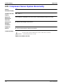
3.13 Malfunctions
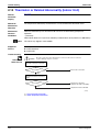
3.13.1 Sensor Malfunction Detection
Sensor malfunction may occur either in the thermistor or current transformer (CT) system.
Relating to Thermistor Malfunction
1. Outdoor heat exchanger thermistor
2. Discharge pipe thermistor
3. Fin thermistor
4. Gas pipe thermistor
5. Outdoor air thermistor
6. Liquid pipe thermistor
Relating to CT Malfunction
When the output frequency is more than 52 Hz and the input current is less than 1.25A, carry
out abnormal adjustment.
3.13.2 Detection of Overload and Overcurrent
Outline
In order to protect the inverter, detect an excessive output current, and for protecting
compressor, monitor the OL operation.
Detail
If the OL (compressor head) temperature exceeds 120~130°C (depending on the
model), the compressor gets interrupted.
If the inverter current exceeds 22 A, the compressor gets interrupted too.
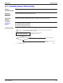
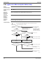
3.13.3 Insufficient Gas Control
Outline
If a power consumption is below the specified value in which the frequency is higher than the
specified frequency, it must be regarded as gas insufficient.
In addition to such conventional function, if the discharge temperature is higher than the target
discharge pipe temperature, and the electronic expansion valve is fully open (450 pulses) more
than the specified time, it is considered as an insufficient gas.
Power consumption
Insufficient gas zone
40 class: 51 Hz
50 class: 48 Hz
Frequency
(R7164)
With the conventional function, a power consumption is weak comparing with that in the normal
operation when gas is insufficient, and gas insufficiency is detected by checking a power
consumption.
Gas insufficient
zone
(R1391)
When operating with insufficient gas, although the rise of discharge pipe temperature is great
and the electronic expansion valve is open, it is presumed as an insufficient gas if the discharge
pipe temperature is higher than the target discharge pipe temperature.
Refer to “Insufficient Gas” on page 147 for detail.
Function and Control
41
Control Specification
Detail
SiBE12-908
Judgment by Input Current
When an output frequency is exceeds 51 Hz (40 class) or 48 Hz (50 class) and the input current
is less than specified value, the adjustment is made for insufficient gas.
Judgment by Discharge Pipe Temperature
When discharge pipe temperature is higher than 101°C, the electronic expansion value opening
is 450 plus (max.) and the adjustment is made for insufficient gas.
3.13.4 Preventing Indoor Freezing
During cooling, if the heat exchanger temperature in the operation stopped room becomes
below the specified temperature for the specified time, open the electronic expansion valve in
the operation stopped room as specified, and carry out the fully closed operation. After this, if
freezing abnormality occurs more than specified time, the system shall be down as the system
abnormality.
3.14 Forced Operation Mode
Outline
Forced operating mode includes only forced cooling.
Detail
Forced Cooling
Item
Forced operation allowing
conditions
Starting/adjustment
Forced Cooling
1) The indoor unit is not abnormal, but the indoor unit which is not in
the freezing prohibiting zone is present in more than 1 room.
2) The outdoor unit is not abnormal and not in the 3-minute standby
mode.
The forced operation is allowed when the above “and” conditions are
met.
When the indoor unit on/off button is pressed for continuous 5 second
as the above conditions are met.
1) Determine operating room All rooms must operate.
2) Command frequency
70Hz (40 class), 47Hz (50 class)
3) Electronic expansion
valve opening
4) Outdoor unit adjustment
5) Indoor unit adjustment
End
Others
42
It depends on the capacity of the operating indoor unit.
Compressor is in operation.
The command of forced cooling operation is transmitted to all indoor
units.
1) When the indoor units on/off button (of the unit which sent the
command) is pressed again.
2) The operation is to end automatically after 15 min.
The protect functions are prior to all others in the forced operation.
Function and Control
SiBE12-908
Control Specification
3.15 Additional Function
3.15.1 POWERFUL Operation Mode
Compressor operating frequency and outdoor unit airflow rate are increased.
3.15.2 Voltage Detection Function
Power supply voltage is detected each time equipment operation starts.
Function and Control
43
Control Specification
44
SiBE12-908
Function and Control
SiBE12-908
Part 5
Installation / Operation
Manual
1. Installation Manual ................................................................................46
1.1 Indoor Units ............................................................................................46
1.2 Outdoor Units .........................................................................................58
2. System Configuration............................................................................70
3. Operation Manual..................................................................................71
3.1
3.2
3.3
3.4
3.5
3.6
3.7
3.8
3.9
3.10
3.11
Installation / Operation Manual
Names of Parts.......................................................................................71
AUTO · DRY · COOL · HEAT · FAN Operation ......................................73
Adjusting the Airflow Direction................................................................75
HUMID HEAT Operation ........................................................................77
FRESH AIR SUPPLY VENTILATION ....................................................79
COMFORT AIRFLOW and INTELLIGENT EYE Operation....................80
POWERFUL and OUTDOOR UNIT QUIET Operation ..........................82
ECONO Operation .................................................................................83
TIMER Operation ...................................................................................84
WEEKLY TIMER Operation ...................................................................86
Note for Multi System .............................................................................91
45
Installation Manual
SiBE12-908
1. Installation Manual
1.1
Indoor Units
Indoor Unit Installation Drawings
How to attach the indoor unit.
Hook the claws of the bottom frame
to the mounting plate.
If the claws are difficult to hook,
remove the front grille.
A Mounting plate
How to remove the indoor unit.
Push up the marked area (at the
lower part of the front grille) to
release the claws. If it is difficult to
release, remove the front grille.
The mounting plate
should be installed on a
wall which can support the
weight of the indoor unit.
A Mounting
plate
Clip
Front grille
Mark (rear side)
If it is difficult to lay the humidifying
hose, cut it, lay it, and connect it using
the joint included with the outdoor unit.
Screws
(Field supply: M4 × 25L)
Do not install the trap to
the humidifying hose as
much as possible.
30mm or more
from ceiling
Install the hose with
a downward slope.
Humidifying
hose
Front panel
Cut thermal insulation
pipe to an appropriate
length and wrap it with
tape, making sure that
no gap is left in the
insulation pipe’s cut line.
50mm or more
from walls
(on both sides)
INTELLIGENT
EYE sensor
M4 × 16L
Air filters
Bottom frame
Wrap the insulation
pipe with the finishing
tape from bottom to top.
M4 × 16L
Air filters
D Air supply filter (gray)
In upward direction
(Left side)
(Right side)
Tabs
(4 locations)
B , C Titanium apatite photocatalytic
air-purifying filter
B (short)
Air supply
filter
C (long)
Service lid
Opening service lid
Service lid is opening/closing type.
Opening method
1) Remove the service lid screws.
2) Pull out the service lid diagonally
down in the direction of the arrow.
3) Pull down.
Filter frame
Air supply filter (gray)
• Hold the knob to pull up.
Filter frame
Tab
Filter frame
Holes
(4 locations)
Air filter
E
Wireless
remote
controller
Screws
(field supply: M3 × 20L)
Before screwing the remote
controller holder to the wall, make
sure that control signals are
properly received by indoor unit.
F
Remote
controller holder
INTELLIGENT EYE sensor
CAUTION
1) Do not hit or violently push the INTELLIGENT EYE sensor. This can lead to damage and malfunction.
2) Do not place large objects near the sensor. Also keep heating units or humidifiers outside the sensor’s detection area.
3
46
Installation / Operation Manual
SiBE12-908
Installation Manual
Preparation before Installation
1.
Removing and installing front panel.
• Removal method
Hook fingers on the tabs on the left and right of the main body, and open
until the panel stops. Slide the front panel sideways to disengage the
rotating shaft. Then pull the front panel toward you to remove it.
• Installation method
Align the tabs of the front panel with the grooves, and push all the way in.
Then close slowly. Push the center of the lower surface of the panel firmly to
engage the tabs.
2.
Removing and installing front grille.
Push the
rotating shaft
of the front
panel into the
groove.
Upper hook
{{{ mark area
(3 locations)
• Removal method
1) Remove front panel to remove the air filter.
2) Remove 2 screws from the front grille.
3) In front of the {{{ mark of the front grille, there are 3 upper hooks.
Lightly pull the front grille toward you with one hand, and push down on the
hooks with the fingers of your other hand.
Lightly pull the front
grille toward you with
one hand, and push
down on the hooks with
the fingers of your other
hand. (3 locations)
Push
down.
Upper hook
Upper hook
When there is no work space because the unit is close to ceiling
CAUTION
Be sure to wear protection gloves.
Place both hands under the center of the front grille, and while pushing up, pull it toward you.
1) Push up.
• Installation method
1) Install the front grille and firmly engage the upper hooks (3 locations).
2) Install 2screws of the front grille.
3) Install the air filter and then mount the front panel.
2) Pull toward you.
4
Installation / Operation Manual
47
Installation Manual
SiBE12-908
Preparation before Installation
3.
How to set the different addresses.
When 2 indoor units are installed in 1 room, the
2 wireless remote controllers can be set for
different addresses.
1) Remove the metal plate electrical wiring
cover.
(Refer to the Removal/attachment methods
of metal plate electrical wiring covers.)
2) Cut the address jumper (JA) on the printed
circuit board.
3) Cut the address jumper (J4) in the remote
controller.
J4
ADDRESS
JA
JA ADDRESS
EXIST
CUT
1
2
J4 ADDRESS
EXIST
1
CUT
2
4.
When connecting to an HA system.
(Wired remote controller, central remote controller etc.)
1) Remove the metal plate electrical
wiring cover.
(Refer to the Removal/
attachment methods of metal
plate electrical wiring covers.)
2) Attach the connection cord to the
S21 connector and pull the
harness out through the notched
part in the figure.
3) Replace the electrical wiring cover
as it was, and pull the harness
around, as shown in the figure.
HA connector
(S21)
HA connector
(S21)
Lay the HA cord as
shown in the figure.
• Removal methods of metal plate electrical wiring covers
1)
2)
3)
4)
Remove the front grille.
Remove the electrical wiring box. (1 screw)
Raise the 2 upper parts of the metal plate electrical wiring cover, pull the parts frontward, and remove the 3 tabs.
Slide the metal plate electrical wiring cover upward and remove the 2 tabs on the lower side.
2) Remove the electrical
wiring box. (1 screw)
3) Raise the 2 upper parts of the
metal plate electrical wiring cover,
pull the parts frontward, and
remove the 3 tabs.
Pull
4) Slide the metal plate electrical wiring
cover upward and remove the 2 tabs on
the lower side.
Slide
Pull
Slide
Pull
Screw
Slide
Tab
Tab
5
48
Installation / Operation Manual
SiBE12-908
Installation Manual
• Attachment methods of metal plate electrical wiring covers
Attach the metal plate electrical wiring covers as shown below.
1) Lean the metal plate electrical wiring cover as shown in the figure and attach tab (1) on the lower side to the electrical
wiring box.
2) Attach tab (2) on the lower side of the metal plate electrical wiring cover.
Tab (1)
Tab (1)
Tab (2)
3) Push in the upper part of the metal plate electrical wiring cover and attach the 3 tabs.
Tab
CAUTION
Make sure that the shaded part (
) will
not go inside the electrical wiring box.
Refrigerant Piping Work
With a multi indoor unit , install as described in the installation manual supplied with the multi outdoor unit.
1.
Flaring the pipe end.
1) Cut the pipe end with a pipe cutter.
2) Remove burrs with the cut surface facing downward
so that the chips do not enter the pipe.
3) Put the flare nut on the pipe.
4) Flare the pipe.
5) Check that the flaring is properly made.
(Cut exactly at
right angles.)
Remove burrs
Flaring
Set exactly at the position shown below.
A
Die
A
Flare tool for R410A
Conventional flare tool
Clutch-type
Clutch-type (Rigid-type) Wing-nut type (Imperial-type)
0-0.5mm
1.0-1.5mm
1.5-2.0mm
Check
Flare’s inner
surface must
be flaw-free.
The pipe end must
be evenly flared in
a perfect circle.
Make sure that the
flare nut is fitted.
WARNING
1)
2)
3)
4)
5)
6)
Do not use mineral oil on flared part.
Prevent mineral oil from getting into the system as this would reduce the lifetime of the units.
Never use piping which has been used for previous installations. Only use parts which are delivered with the unit.
Do never install a drier to this R410A unit in order to guarantee its lifetime.
The drying material may dissolve and damage the system.
Incomplete flaring may cause refrigerant gas leakage.
6
Installation / Operation Manual
49
Installation Manual
SiBE12-908
Refrigerant Piping Work
2.
Refrigerant piping.
CAUTION
1) Use the flare nut fixed to the main unit. (To prevent cracking of the flare nut by aged deterioration.)
2) To prevent gas leakage, apply refrigeration oil only to the inner surface of the flare. (Use refrigeration oil for R410A.)
3) Use torque wrenches when tightening the flare nuts to prevent damage to the flare nuts and gas leakage.
Align the centres of both flares and tighten the flare nuts 3 or 4 turns by hand. Then tighten them fully with the torque wrenches.
[Apply oil]
[Tighten]
Apply refrigeration oil to
Do not apply refrigeration
oil to the outer surface.
Torque wrench
the inner surface of the
flare.
Flare nut
Spanner
Piping union
Flare nut
Do not apply refrigeration
oil to the flare nut avoid
tightening with over torque.
Flare nut tightening torque
Gas side
Liquid side
25/35/42 class
50 class
3/8 inch
1/2 inch
1/4 inch
32.7-39.9N • m
49.5-60.3N • m
14.2-17.2N • m
(330-407kgf • cm)
(505-615kgf • cm)
(144-175kgf • cm)
2-1. Caution on piping handling.
1) Protect the open end of the pipe against dust and moisture.
2) All pipe bends should be as gentle as possible. Use a pipe bender
for bending.
Wall
Be sure to
place a cap.
Rain
If no flare cap is
available, cover the
flare mouth with
tape to keep dirt or
water out.
2-2. Selection of copper and heat insulation materials.
• When using commercial copper pipes and fittings, observe the following:
1) Insulation material: Polyethylene foam
Heat transfer rate: 0.041 to 0.052W/mK (0.035 to 0.045kcal/(mh•˚C))
Refrigerant gas pipe’s surface temperature reaches 110˚C max.
Choose heat insulation materials that will withstand this temperature.
2) Be sure to insulate both the gas and liquid piping and to provide insulation
dimensions as below.
Gas side
Liquid side
25/35/42 class
50 class
O.D. 9.5mm
O.D. 12.7mm
O.D. 6.4mm
Minimum bend radius
30mm or more
40mm or more
30mm or more
Thickness 0.8mm (C1220T-O)
Finishing tape
Inter-unit wiring
Gas pipe
Drain hose
Gas pipe
insulation
Liquid pipe insulation
Liquid pipe
Humidifying
hose
Gas pipe thermal insulation
Liquid pipe
thermal insulation
25/35/42 class
50 class
I.D. 12-15mm
I.D. 14-16mm
I.D. 8-10mm
Thickness 10mm Min.
3) Use separate thermal insulation pipes for gas and liquid refrigerant pipes.
7
50
Installation / Operation Manual
SiBE12-908
Installation Manual
Indoor Unit Installation
1.
Installing the mounting plate.
• The mounting plate should be installed on a wall which can support the weight of the indoor unit.
1) Temporarily secure the mounting plate to the wall, make sure that the panel is completely level, and mark the boring
points on the wall.
2) Secure the mounting plate to the wall with screws.
Recommended mounting plate retention spots and dimensions
Place a leveler on raised tab.
103
450
400
Bilt size: M10
200
Bilt size: M10
Through the wall
hole φ70mm
36
Gas pipe end
61
Liquid pipe end
175.5
149
278.5
Drain hose position
50
44.5 60.5
φ70
φ70
44.5
Use tape measure
as shown.
Position the end
of a tape measure
at .
295
45.5
45.5
56.5
115
147.5
Recommended mounting
plate retention spots.
(5 spots in all)
60.5
Keep here the piece cut out
800 from the unit for piping.
unit: mm
* The removed pipe port cover can be
kept in the mounting plate pocket.
Removed pipe
port cover
A Mounting plate
2.
Boring a wall hole and installing wall embedded pipe.
• For walls containing metal frame or metal board, be sure to use a wall
embedded pipe and wall cover in the feed-through hole to prevent possible
heat, electrical shock, or fire.
• Be sure to caulk the gaps around the pipes with caulking material to prevent
water leakage.
1) Bore a feed-through hole of 70mm in the wall so it has a down slope toward
the outside.
2) Insert a wall pipe into the hole.
3) Insert a wall cover into wall pipe.
4) After completing refrigerant piping, wiring, and drain piping, caulk pipe hole
gap with putty.
Inside
Wall embedded pipe
(field supply)
Wall hole cover
(field supply)
Outside
Caulking
φ70
Wall embedded pipe
(field supply)
8
Installation / Operation Manual
51
Installation Manual
SiBE12-908
Indoor Unit Installation
3.
Inter-unit wiring.
1) Open the front panel, then remove the service lid.
2) Pass the inter-unit wiring from the outdoor unit through the
feed-through wall hole and then through the back of the indoor
unit. Pull them through the front side. Bend the ends of tie
wires upward for easier work in advance. (If the inter-unit
wiring ends are to be stripped first, bundle wire ends with
adhesive tape.)
3) Press the bottom frame of the indoor unit with both hands to
set it on the mounting plate hooks. Make sure the wires do not
catch on the edge of the indoor unit.
4.
Hang indoor unit’s hook here.
A Mounting plate
When stripping the
ends of inter-unit wiring
in advance, bind right
ends of wires with
insulating tape.
Inter-unit wiring
Humidifying hose installation work.
CAUTION
• Be sure to use humidifying hose sold as optional accessory. (KPMH996A10S (10m set), KPMH996A15S (15m set))
1) The length of the humidifying hose needs to be set to ensure humidifying capacity. Cut off any excess hose.
Use the remote controller to set the hose length. (Refer to page 13.)
• Attach a cover to the end of each humidifying hose so that no moisture or foreign substance will go into the hose when
leaving the hose without being connected to the outdoor and indoor units.
• When laying the humidifying hose inside the wall, block the ends of the humidifying hose with tape or the like to prevent
water or anything else from entering it until it is connected to the indoor unit and outdoor unit ducts.
• Do not bend the humidifying hose more than 90˚.
• Use caution not to deform the cuff while installing the humidifying hose.
4-1. Connecting to the indoor unit.
• Connect the cuff side of the humidifying hose to the indoor unit duct.
• Use the humidifying hose of suitable length as shown below.
10m set: the 8m hose
15m set: the 2m hose
• When connecting the humidifying hoses of the indoor and outdoor units, refer to the installation manual provided to
the outdoor unit.
It is easier to connect the hose
with the front grille removed.
Pulling out the
humidifying hose in a
sideward direction.
Cuff
Humidifying
hose
Connect the
cuff side of the
humidifying
hose to the
indoor unit duct.
Insert as far as possible
so that there are no gaps.
Pulling out the
humidifying hose in a
downward direction.
• Left-back piping
Cut the cuff
at this part.
(If it is too long, cut the humidifying hose
and bond the separately sold cuff with
adhesive for vinyl to adjust the length.)
Approx. 100mm
The protrusion of the
humidifying hose from the
wall hole is about 100mm.
9
52
Installation / Operation Manual
SiBE12-908
5.
Installation Manual
Laying piping, hoses, and wiring.
• Connect the humidifying hose to the indoor unit duct.
See 4. Humidifying hose installation work for details.
• Lay the piping, drain hose and humidifying hose
according to the orientation of the piping coming out of
the unit, as shown below.
• Make sure the drain hose is sloped downward.
• Wrap the piping, drain hose and humidifying hose
together using insulation tape.
Piping bundle diagram
Inter-unit wiring
Gas pipe
Drain hose
Liquid pipe
Insulation tape
Humidifying
hose
5-1. Right-side, right-back, or right-bottom piping.
• Right-side piping
• Right-back piping
• Right-bottom piping
Cut out the
piping-through hole.
It is recommended
to use the elbow.
Install with a
downward slope.
Cut out the
piping-through hole.
Humidifying hose
Humidifying hose
Humidifying hose
1) Wrap the pipes, hoses and inter-unit wiring using insulation tape as shown in the piping bundle diagram.
2) Put all the pipes through the through-hole in the wall and hook the indoor unit onto the
3) Connect the pipes.
A
mounting plate.
A Mounting plate
5-2. Left-side, left-back, or left-bottom piping.
How to replace the drain plug and drain hose.
• Replacing onto the left side
1) Remove the insulation fixing screws on the right
to remove the drain hose.
2) Remove the drain plug on the left side and
attach it to the right side.
3) Insert the drain hose and tighten with the
screws which were removed at STEP 1).
Drain hose attachment position
* The drain hose is on the back of the unit.
Left side
Right side
Front side of unit
Attachment on the left side
Attachment on the right side
(factory default)
Indoor unit
fixing screw
Insulation
fixing screw
Drain hose
Drain hose
How to set drain plug
p.
a
No g
Do not apply lubricating oil
(refrigeration oil) when inserting.
Application of causes deterioration
and drain leakage of the plug.
Insert a hexagon wrench (4mm).
10
Installation / Operation Manual
53
Installation Manual
SiBE12-908
Indoor Unit Installation
• Left-side piping
• Left-back piping
• Left-bottom piping
Humidifying hose
Refrigerant pipe
Drain hose
Cut out the
piping-through hole.
Cut out the
piping-through hole.
Refrigerant pipe
Refrigerant pipe
Humidifying hose
1) Replace the drain plug and drain hose. (How to replace the drain plug and drain hose.)
2) Pull in the refrigerant piping and lay it so that it matches the liquid and gas piping marked on the
A
mounting plate.
3) Hook the indoor unit onto the A mounting plate.
4) Connect the pipes. If it is difficult to do, remove the front grille first.
5) Wrap the insulation on the
piping with insulation tape. If
you are not replacing the drain
hose, store it in the location
shown as right figure.
Drain hose
A Mounting plate
Caulk this hole
with putty or
caulking material.
Bind with
plastic tape.
6) While exercising care so that the inter-unit wiring do not catch indoor
unit, press the bottom edge of indoor unit with both hands until it is
firmly caught by the mounting plate hooks. Secure indoor unit to the
mounting plate with screws (M4 × 12L).
Wrap insulating tape around the bent portion
of refrigerant pipe.
Overlap at least half the width of the tape
with each turn.
Inter-unit wiring
Drain hose
A
Mounting
plate
Refrigerant
pipes
Bottom frame
H M4 × 12L (2 point)
5-3. Wall embedded piping.
Follow the instructions given under
Left-side, left-back, or left-bottom piping .
1) Insert the drain hose to this depth so it won’t be pulled out of the drain
pipe.
Insert the drain hose
to this depth so it
won’t be pulled out
of drain pipe.
Inner wall
50mm
or more
Drain hose
Outer wall
Vinyl chloride
drain pipe
(VP-30)
11
54
Installation / Operation Manual
SiBE12-908
Installation Manual
6.
Wiring.
With a multi indoor unit , install as described in the installation manual supplied with the multi outdoor
unit.
1) Strip wire ends (15mm).
2) Match wire colours with terminal numbers on indoor and outdoor unit’s terminal blocks and firmly screw wires to the
corresponding terminals.
3) Connect the earth wires to the corresponding terminals.
4) Pull wires to make sure that they are securely latched up, then retain wires with wire retainer.
5) In case of connecting to an adapter system. Run the remote controller cable and attach the S21.
6) Shape the wires so that the service lid fits securely, then close service lid.
Firmly fix the wires with
the terminal screws.
Terminal block
Electrical component box
1 2
3
Outdoor unit
Shape wires so that the
service lid will fit securely.
Firmly secure wire retainer so that
wires sustain no external stress.
Use the specified
wire type.
1 23
When wire length exceeds
10m, use 2.0mm diameter wires.
Indoor
unit
Wire retainer
LN
1
2
3
Firmly fix the wires with
the terminal screws.
H05RN
WARNING
1) Do not use tapped wires, strand wires, extensioncords, or starburst connections, as they may cause overheating, electrical
shock, or fire.
2) Do not use locally purchased electrical parts inside the product. (Do not branch the power for the drain pump, etc., from the
terminal block.) Doing so may cause electric shock or fire.
7.
Drain piping.
The drain hose should
be inclined downward.
1) Connect the drain hose, as described right.
No trap is permitted.
Do not put the end
of the hose in water.
3) When drain hose requires extension, obtain an extension hose commercially
available.
Be sure to thermally insulate the indoor section of the extension hose.
Indoor unit
drain hose
φ18
2) Remove the air filters and pour some water into the drain pan to check the water
flows smoothly.
Extension drain hose
4) When connecting a rigid polyvinyl chloride pipe
(nominal diameter 13mm) directly to the drain
hose attached to the indoor unit as with
embedded piping work, use any commercially
available drain socket (nominal diameter 13mm)
as a joint.
φ18
Heat insulation tube
(field supply)
Drain hose supplied with
the indoor unit
Commercially available drain
socket
(nominal diameter 13mm)
Commercially available rigid
polyvinyl chloride pipe
(nominal diameter 13mm)
12
Installation / Operation Manual
55
Installation Manual
SiBE12-908
b
Setting the Humidifying Hose Length
CAUTION
If the humidifying hose length is not set or it is set incorrectly, the humidifying capacity may diminish or strange sound may
occur from humidifying hose.
1.
Setting the humidifying hose length.
Set the humidifying hose length to ensure humidifying capacity. Use the remote
controller to set the humidifying hose length. When doing this, power on the unit
as communication is established between the unit and the remote controller.
Be sure to direct the remote controller toward the indoor unit while setting the
humidifying hose length.
(The humidifying hose length includes the rear of the indoor unit.)
• Set the humidifying hose length according the following procedure after
A
check the installed hose length.
LCD
B
Pipe set mode (Hose length setting)
1) Press “MODE” button and “TEMP” button (2 locations) at the same time.
(To cancel, do not operate the button for 60 seconds. The display will return to
normal.)
C
A: TEMP button
B: MODE selector button
C: CANCEL button
2) Press “TEMP
” button and select “
” (Pipe set mode).
3) Press “MODE” button to activate the Pipe set mode.
(When the unit receive signal, the sound emitted. Be sure to check the sound.
If the sound is not heard, press “MODE” button again.)
” button changes the humidifying hose length.
4) Pressing “TEMP
You may set the hose length to 6 levels:
“
”, “
“ ”, “ ” “ ”, “ ” “ ”, “ ” “ ” , “ ” ” .
5) Hold “MODE” button for more than 2 seconds.
The display changes to “
” (Pipe check mode).
6) Press “MODE” button again to activate the pipe check mode.
(Set point)
” button and select the hose length.
7) Press “TEMP
Beep sound indicate that the setting of the remote controller accords or
disaccord with the unit.
• accord: a long beep
• disaccord: a short beep
If you set the wrong humidifying hose length, press “CANCEL” button.
The display returns to step 4). Reset the hose length.
Cancel
Pipe check mode (Hose length check)
8) Hold “MODE” button for more than 5 seconds.
The humidifying hose length setting is complete and the display returns to
normal.
2.
When the unit cannot be powered on.
When setting the humidifying hose length without powering on the unit, the indoor unit does not
receive the information at step 3) and 5) shown above. However, the remote controller stores the
humidifying hose length information.
(When the customer uses the unit, the humidifying hose length information is send to the indoor unit
to be set.)
(Set point;
long beep)
13
56
Installation / Operation Manual
SiBE12-908
Installation Manual
a
Trial Operation and Testing
1.
Trial operation and testing.
1-1 Measure the supply voltage and make sure that it falls in the specified range.
1-2 Trial operation should be carried out in either cooling or heating mode.
• In cooling mode, select the lowest programmable temperature; in heating mode, select the highest programmable
temperature.
1) Trial operation may be disabled in either mode depending on the room temperature.
Use the remote controller for trial operation as described below.
2) After trial operation is complete, set the temperature to a normal level (26˚C to 28˚C in cooling mode, 20˚C to 24˚C in
heating mode).
3) For protection, the system disables restart operation for 3 minutes after it is turned off.
1-3 To perform a test run for HUMID HEAT operation, activate test run mode from the remote controller following
the instructions below and select the HUMID HEAT operation.
1-4 Carry out the test operation in accordance with the operation manual to ensure that all functions and parts,
such as louver movement, are working properly.
• The air conditioner requires a small amount of power in its standby mode. If the system is not to be used for some
time after installation, shut off the circuit breaker to eliminate unnecessary power consumption.
• If the circuit breaker trips to shut off the power to the air conditioner, the system will restore the original operation
mode when the circuit breaker is opened again.
Trial operation from remote controller
1)
2)
3)
4)
5)
2.
Press “ON/OFF” button to turn on the system.
Press “TEMP” button (2 locations) and “MODE” button at the same time.
Press “TEMP
” button and select “ ” (TEST mode).
Press “MODE” button.
Trial run mode terminates in approx. 30 minutes and switches into normal mode. To quit a trial operation, press
“ON/OFF” button.
Test items.
Test items
Symptom
(diagnostic display on RC)
Indoor and outdoor units are installed properly on solid bases.
Fall, vibration, noise
No refrigerant gas leaks.
Incomplete cooling/heating function
Refrigerant gas and liquid pipes and indoor drain hose extension are thermally
insulated.
Water leakage
Draining line is properly installed.
Water leakage
System is properly earthed.
Electrical leakage
The specified wires are used for inter-unit wiring connections.
Inoperative or burn damage
Indoor or outdoor unit’s air intake or exhaust has clear path of air.
Stop valves are opened.
Incomplete cooling/heating function
Indoor unit properly receives remote controller commands.
Inoperative
No strange noise from the humidifying hose.
Bubble sound*
Check
* When the bubble sound is heard, water may be in the humidifying hose.
Do the HOSE DRY operation.
HOSE DRY operation for humidifying hose
1) Press “TEMP” button (2 locations) and “MODE” button at the same time.
2) Press “TEMP
” button and select “D” (DRYING mode).
3) Press “MODE” button to start the HOSE DRY operation.
HOSE DRY operation will work about 30 minutes.
(To cancel the HOSE DRY operation, hold “MODE” button for more than 5 seconds.)
4) Activate test run for HUMID HEAT operation again, check that the bubble sound is not heard from the humidifying hose.
14
3P232706-1B
Installation / Operation Manual
57
Installation Manual
1.2
SiBE12-908
Outdoor Units
Outdoor Unit Installation Drawings
1.
Precautions for humidifying hose installation work.
• Moisture on the outdoor unit is brought to the indoor unit together with air around the outdoor unit during humidifying
operation. Install the outdoor unit in a clean and calm location.
• Be sure to use the humidifying hose sold as an optional accessory. (KPMH996A10S (10m set), KPMH996A15S (15m set))
CAUTION
Do not connect the embedded branch piping and the outdoor unit when only carrying out piping work without connecting the
indoor unit in order to add another indoor unit later.
Make sure no dirt or moisture gets into either side of the embedded branch piping.
See “Precautions for Laying Refrigerant Piping” on page 9 for details.
Installation of humidifying hoses, respectively, in upward direction in ROOM A and in downward direction
in ROOM B.
<Front side>
Allow 300mm of
work space below
the ceiling surface.
<Back side>
Humidifying hose
ROOM A
Wire
Humidifying hose
ROOM B
Humidifying hose
ROOM A
250mm from
wall
ROOM B
of
ch
pit s)
ole olt
(H ot b
fo
1
31
(Hole
574
pitch o
f foot b
o
lts)
If there is the danger of the unit
falling or overturning, fix the unit
with foundation bolts, or with wire
or other means.
Stop valve cover
Level mounting base
(available separately)
If the location does not have good drainage,
place the unit on a level mounting base (or a
plastic pedestal). Install the outdoor unit in a
level position. Failure to do so may result in
water leakage or accumulation.
unit: mm
Also insulate the connection on the outdoor unit.
Clamping material
Insulation tube
Tape
Stop valve cover
Use tape or insulating material on all connections
to prevent air from getting in between the copper
piping and the insulation tube.
Be sure to do this if the outdoor unit is installed
above.
3
58
Installation / Operation Manual
SiBE12-908
Installation Manual
Installation
• Install the unit horizontally.
• The unit may be installed directly on a concrete verandah or a solid place if drainage is good.
• If the vibration may possibly be transmitted to the building, use a vibration-proof rubber (field supply).
1.
Connections (connection port).
Install the indoor unit according to the table below, which shows the relationship between the class of indoor unit and the
corresponding port.
The total indoor unit class that can be connected to this unit:
2MXU40G∗
2MXU50G∗
Up to 6.0kW
Up to 8.5kW
Port
2MXU40G∗
A
25 , 35
25 , 35 , 42
B
25 , 35
25 , 35 , 42 , 50
2MXU50G∗
: Use a reducer to connect pipes.
Refer to “How to Use Reducers” for information on reducer numbers and their shapes.
How to Use Reducers
No.1
φ12.7→ φ9.5
No.2
φ12.7 → φ9.5
Gasket (1)
Gasket (2)
Use the reducers supplied with the unit as described below.
• Connecting a pipe of φ9.5 to a gas pipe connection port for φ12.7:
Inter-unit piping
No. 2
No. 1
Connection port of outdoor unit
Flare nut (for φ12.7)
Be sure to attach the gasket.
• When using the reducer packing shown above, be careful not to overtighten
the nut, or the smaller pipe may be damaged (about 2/3 - 1 the normal torque).
• Apply a coat of refrigeration oil to the threaded connection port of the outdoor
unit where the flare nut comes in.
• Use an appropriate wrench to avoid damaging the connection thread by overtightening the flare nut.
Flare nut tightening torque
Flare nut for
φ12.7
49.5–60.3N·m
(505–615kgf·cm)
Precautions on Installation
20
• Check the strength and level of the installation ground so that the unit will not cause any operating vibration or noise after installed.
• In accordance with the foundation drawing in fix the unit securely by means of the foundation bolts. (Prepare four sets of M8 or
M10 foundation bolts, nuts and washers each which are available on the market.)
• It is best to screw in the foundation bolts until their length are 20mm from the foundation surface.
4
Installation / Operation Manual
59
Installation Manual
SiBE12-908
Outdoor Unit Installation Guideline
• Where a wall or other obstacle is in the path of outdoor unit’s intake or exhaust airflow, follow the installation guidelines below.
• For any of the below installation patterns, the wall height on the exhaust side should be 1200mm or less.
Walls facing two sides
Wall facing one side
More than 50
More than 100
More than 150
More
than 100
1200
or less
More than 50
More than 50
Top view
Side view
Walls facing three sides
More than 150
More than 300
More than 50
Top view
unit: mm
Selecting a Location for Installation of
the Indoor Units
• The maximum allowable length of refrigerant piping, and the maximum allowable height difference between the outdoor and indoor
units, are listed below.
(The shorter the refrigerant piping, the better the performance. Connect so that the piping is as short as possible. Shortest allowable length per room is 3m.)
Piping to each indoor unit
ROOM A, B: 15m max.
Total length of piping between all units
30m max.
Indoor Unit
Outdoor Unit
Level
difference:
15m max.
Level
difference:
7.5m max.
If the outdoor unit is positioned higher than the
indoor units.
Level
difference:
15m max.
Level
difference:
7.5m max.
Outdoor Unit
Indoor Unit
If the outdoor unit is positioned otherwise.
(If lower than one or more indoor units.)
5
60
Installation / Operation Manual
SiBE12-908
Installation Manual
Refrigerant Piping Work
1.
Installing outdoor unit.
1) When installing the outdoor unit, refer to “Precautions for Selecting the Location” on page 2 and the “Outdoor Unit
Installation Drawings” on page 3.
2) If drain work is necessary, follow the procedures below.
2.
Drain work.
1) Use C drain plug for drainage.
2) If the drain port is covered by a mounting base or floor surface, place
additional foot bases of at least 30mm in height under the outdoor
unit’s feet.
3) In cold areas, do not use a drain hose with the outdoor unit.
(Otherwise, drain water may freeze, impairing heating performance.)
3.
Drain-water hole
Bottom frame
C Drain plug
Hose (available commercially,
inner dia. 16mm)
Refrigerant piping.
CAUTION
1) Use the flare nut fixed to the main unit. (To prevent cracking of the flare nut by aged deterioration.)
2) To prevent gas leakage, apply refrigeration oil only to the inner surface of the flare. (Use refrigeration oil for R410A.)
3) Use torque wrenches when tightening the flare nuts to prevent damage to the flare nuts and gas leakage.
Align the centres of both flares and tighten the flare nuts 3 or 4 turns by hand. Then tighten them fully with the torque wrenches.
[Apply oil]
Do not apply refrigeration
oil to the outer surface.
[Tighten]
Apply refrigeration oil to
the inner surface of the
Torque wrench
flare.
Flare nut
Spanner
Piping union
Flare nut
Do not apply refrigeration
oil to the flare nut avoid
tightening with over torque.
Flare nut tightening torque
14.2-17.2N • m
(144-175kgf • cm)
32.7-39.9N • m
Flare nut for φ9.5
(333-407kgf • cm)
49.5-60.3N • m
Flare nut for φ12.7
(505-615kgf • cm)
Flare nut for φ6.4
Valve cap tightening torque
Gas side
Liquid side
3/8 inch
1/2 inch
1/4 inch
21.6-27.4N • m
48.1-59.7N • m
21.6-27.4N • m
(220-280kgf • cm) (490-610kgf • cm) (220-280kgf • cm)
Service port cap
tightening torque
10.8-14.7N • m
(110-150kgf • cm)
6
Installation / Operation Manual
61
Installation Manual
SiBE12-908
Refrigerant Piping Work
4.
Purging air and checking gas leakage.
WARNING
1)
2)
3)
4)
•
•
•
•
Do not mix any substance other than the specified refrigerant (R410A) into the refrigeration cycle.
When refrigerant gas leaks occur, ventilate the room as soon and as much as possible.
R410A, as well as other refrigerants, should always be recovered and never be released directly into the environment.
Be sure to check for gas leaks.
Be sure to perform vacuum pumping for all the rooms at the same time.
Be sure to use the special tools for the R410A (gauge manifold, charge hose, vacuum pump, vacuum pump adapter, etc.).
Use a hexagonal wrench (4mm) to operate the stop valve rod.
All refrigerant pipe joints should be tightened with a torque wrench at the specified tightening torque.
1) Connect the charge hose protrusions (the side for pushing the pin) for low pressure and high pressure on the gauge manifold
to the gas stop valve service port for rooms A and B.
2) Fully open gauge manifold’s low-pressure valve (Lo) and high-pressure valve (Hi).
3) Apply vacuum pumping for 20 minutes or longer. Check that the compound pressure gauge reads –0.1MPa (–76cmHg).
4) After checking the vacuum, close the low pressure and high pressure valves on the gauge manifold and stop the vacuum
pump. (Leave as is for 4-5 minutes and make sure the coupling meter needle does not go back. ) If it does go back, this may
indicate the presence of moisture or leaking from connecting parts.
After inspecting all the connection and loosening then retightening the nuts, repeat steps 2) → 3) → 4).
5) Remove the valve caps on the liquid and gas stop valves at the pipes for rooms A and B.
6) Open the valve rods on the liquid stop valves for rooms A and B by turning them 90˚ counterclockwise using a hex wrench.
Close them 5 seconds later and check for gas leaks.
After checking for gas leaks, check the areas around flares on the indoor unit, and the areas around flares and valve rods on
the outdoor unit by applying soapy water.
Wipe down thoroughly after the check is complete.
7) Remove the charge hose from the gas stop valve service ports at the pipes for rooms A and B and completely open the liquid
and gas stop valves at the pipes for rooms A and B.
(Stop the valve rods as far as they go and do not attempt to turn them any further.)
8) Use a torque wrench to tighten the valve caps and service port caps on the liquid and gas stop valves at the pipes for rooms
A and B to the designated torque.
Compound
gauge
Gauge manifold
Valve cap
Low-pressure valve
Room A liquid
stop valve
Room A gas
stop valve
Room B liquid
stop valve
High-pressure valve
Charge hose
Room B gas
stop valve
Vacuum pump adapter
Vacuum pump
Service port
7
62
Installation / Operation Manual
SiBE12-908
Installation Manual
5.
Refilling the refrigerant.
Check the type of refrigerant to be used on the machine nameplate.
Precautions when adding R410A
Fill from the liquid pipe in liquid form.
It is a mixed refrigerant, so adding it in gas form may cause the refrigerant composition to change, preventing normal operation.
1) Before filling, check whether the cylinder has a siphon attached or not. (It should have something like “liquid filling siphon
attached” displayed on it.)
Filling a cylinder with an attached siphon
Filling other cylinders
Stand the cylinder upright when filling.
Turn the cylinder upside-down
when filling.
There is a siphon pipe inside, so the
cylinder need not be upside-down to
fill with liquid.
2) Be sure to use the R410A tools to ensure pressure and to prevent foreign objects entering.
6.
Charging with refrigerant.
• If the total length of piping for all rooms exceeds 20m, additionally charge with (R410A) 20g of refrigerant for each
additional meter of piping.
Important information regarding the refrigerant used
This product contains fluorinated greenhouse gases covered by the Kyoto Protocol.
Do not vent gases into the atmosphere.
Refrigerant type: R410A
GWP(1) value:
(1) GWP
1975
= global warming potential
Please fill in with indelible ink,
1 the factory refrigerant charge of the product,
2 the additional refrigerant amount charged in the field and
1 + 2 the total refrigerant charge
on the refrigerant charge label supplied with the product.
The filled out label must be adhered in the proximity of the product charging port (e.g. onto the inside of the stop valve
cover).
4
1 factory refrigerant charge of the product: see unit name plate
2 additional refrigerant amount charged in the field
1
2
3 total refrigerant charge
4 Contains fluorinated greenhouse gases covered by the Kyoto Protocol
5 outdoor unit
3
6
6 refrigerant cylinder and manifold for charging
5
NOTE:
National implementation of EU regulation on certain fluorinated greenhouse gases may require to provide the appropriate
official national language on the unit. Therefor an additional multilingual fluorinated greenhouse gases label is supplied
with the unit.
Sticking instructions are illustrated on the backside of that label.
CAUTION
1) Even though the stop valve is fully closed, the refrigerant may slowly leak out; do not leave the flare nut removed for a long
period of time.
2) Do not overfill with refrigerant. This will break the compressor.
8
Installation / Operation Manual
63
Installation Manual
SiBE12-908
Refrigerant Piping Work
Precautions for Laying Refrigerant Piping
• Cautions on pipe handling
Rain
If no flare cap is
available, cover
the flare mouth
with tape to keep
dirt or water out.
1) Protect the open end of the pipe against dust and moisture.
2) All pipe bends should be as gentle as possible. Use a pipe bender for
bending.
• Selection of copper and heat insulation materials
Finishing tape
When using commercial copper pipes and fittings, observe the following:
1) Insulation material: Polyethylene foam
Heat transfer rate: 0.041 to 0.052W/mK (0.035 to 0.045kcal/mh˚C)
Refrigerant gas pipe’s surface temperature reaches 110˚C max.
Choose heat insulation materials that will withstand this temperature.
2) Be sure to insulate both the gas and liquid piping and to provide insulation
dimensions as below.
Gas side
40 or 50class
50 class
O.D. 9.5mm
O.D. 12.7mm
Minimum bend radius
30mm or more
40mm or more
Drain hose
Gas pipe
insulation
Liquid pipe insulation
40 class
O.D. 6.4mm
Inter-unit wiring
Gas pipe
Gas pipe thermal insulation
Liquid side
Wall
Be sure to
place a cap.
Liquid pipe
Humidifying
hose
Liquid pipe
thermal insulation
50 class
I.D. 12-15mm
I.D. 8-10mm
Thickness 13mm Min.
Thickness
10mm Min.
30mm or more
Thickness 0.8mm (C1220T-O)
3) Use separate thermal insulation pipes for gas and liquid refrigerant pipes.
• Flaring the pipe end
1) Cut the pipe end with a pipe cutter.
2) Remove burrs with the cut surface facing
downward so that the chips do not enter the pipe.
3) Put the flare nut on the pipe.
4) Flare the pipe.
5) Check that the flaring is properly made.
(Cut exactly at
right angles.)
Remove burrs
Flaring
Set exactly at the position shown below.
A
Die
A
Flare tool for R410A
Conventional flare tool
Clutch-type
Clutch-type (Rigid-type) Wing-nut type (Imperial-type)
0-0.5mm
1.0-1.5mm
1.5-2.0mm
Check
Flare’s inner
surface must
be flaw-free.
The pipe end must
be evenly flared in
a perfect circle.
Make sure that the
flare nut is fitted.
WARNING
1)
2)
3)
4)
5)
6)
Do not use mineral oil on flared part.
Prevent mineral oil from getting into the system as this would reduce the lifetime of the units.
Never use piping which has been used for previous installations. Only use parts which are delivered with the unit.
Do never install a drier to this R410A unit in order to guarantee its lifetime.
The drying material may dissolve and damage the system.
Incomplete flaring may cause refrigerant gas leakage.
9
64
Installation / Operation Manual
SiBE12-908
Installation Manual
Pump Down Operation
In order to protect the environment, be sure to pump down when relocating or disposing of the unit.
1) Remove the valve caps on the liquid and the gas stop valves at the pipes for rooms A
and B.
2) Run the unit on forced cooling. (Refer to the below.)
3) After 5 to 10 minutes, close the liquid stop valves at the pipes for rooms A and B
using a hex wrench.
4) After 2 to 3 minutes, stop the FORCED COOLING operation as quickly as possible
after the gas stop valves at the pipes for rooms A and B have been shut off.
5) Turn the power breaker off.
Liquid
stop valve
Hexagonal
wrench
Close
Gas
stop valve
Valve cap
CAUTION
Run the air conditioner to cool both rooms A and B when performing a pump down.
1.
FORCED COOLING operation.
1-1. Using the indoor unit “ON/OFF” button.
1) Press the “ON/OFF” button on the indoor unit in either room A or B for 5 seconds continuously.
The units in both rooms will start.
2) FORCED COOLING operation will end after around 15 minutes and the unit will stop automatically. Press the
“ON/OFF” button on the indoor unit to FORCED COOLING operation to stop.
3) Use this method to FORCED COOLING operation when the outside temperature is 10˚C or lower.
1-2. Using the wireless remote controller.
1) Select cooling operation and press the “ON/OFF” button. (The unit will start.)
2) Press the “TEMP
” button (2 locations), and the “MODE” button at the same time.
3) Press the “MODE” button twice.
( will be displayed and the unit will go into test-run mode.)
4) Test-run mode will end after around 30 minutes and the unit will stop automatically. Press the “ON/OFF” button to
force the test-run to stop.
CAUTION
If the outside temperature is 10˚C or lower, the safety device might start, preventing operation. In this situation, warm the outside
temperature thermistor on the outdoor unit to 10˚C or warmer. Operation will start.
Connecting the Humidifying Hose
Either one of the following sets (optional accessories) is required when connecting humidifying hoses.
Prepare the 10 or 15m set according to the conditions of the site.
<Optional accessories>
KPMH996A10S (10m set)
A Joint (φ25)
Humidifying hose
B Binding band
C 8m (With cuff)
(I.D. 25mm
O.D. 35mm)
1
2
E Installation manual
D 2m (With cuff)
(I.D. 25mm
O.D. 35mm)
1
1
1
KPMH996A15S (15m set)
F Joint
(φ30)
1
G Reducing
joint
(φ30→φ25)
2
Humidifying hose
B Binding band
6
H 7.5m
(I.D.
30mm
O.D.
46mm)
1
J 3.5m
(I.D.
30mm
O.D.
46mm)
1
D 2m (With cuff)
(I.D.
25mm
O.D.
35mm)
2
E Installation
manual
1
10
Installation / Operation Manual
65
Installation Manual
SiBE12-908
Connecting the Humidifying Hose
1.
Connecting to indoor unit.
Keep the following items in mind in order to prevent the degrading of humidification performance when connecting the humidifying
hose to the indoor unit.
1) Cut the excessive portions of the humidifying hoses.
* Determine the overall length of the humidifying hoses according to the installation manual for the indoor unit.
2) Be sure to avoid traps as much as possible when installing the humidifying hoses.
3) Be careful not to crush the humidifying hoses in the case of bending the hoses at the time of
installation. Furthermore, make sure that the maximum bending radius will not exceed 90˚.
4) Check that the overall length of the humidifying hoses is definitely 3m or more.
5) Attach a cover to the end of each humidifying hose so that no moisture or foreign substance
Cover
will go into the hose when leaving the hose without being connected to the outdoor and
Humidifying
indoor units.
hose
Outdoor
Indoor
<Indoor unit>
CAUTION
• Make sure that the number of bending times will not exceed the
following limits at the time of installation.
3m-8m
:3 times
8.1m-10m :4 times
10.1m-15m :5 times
• Use the KPMH996A15S (15m set) only if the overall length of
the humidifying hoses exceeds 10m.
Connect the humidifying hose according to
the installation manual for the indoor unit.
Mark the cuff on the indoor unit side so
that the overall length of the hoses after
adjustment will be clearly known.
Connect the hose
according to the
instructions on page 12
of this manual.
Use the provided joint to connect the humidifying hoses.
Insert the joint into the humidifying hoses so that there
will be no clearance between the hoses on the joint,
and secure the position of 10mm from the end of each
hose with a binding band.
B Binding
band
<Outdoor unit>
■ Connecting KPMH996A10S (10m set)
■ Connecting KPMH996A15S (15m set)
1) Be sure to connect the C 8m hose to the indoor unit and
the D 2m hose to the outdoor unit, respectively, and join
the 2 hoses with the A joint.
• Use the KPMH996A15S (15m set) only if the overall length of the
humidifying hoses exceeds 10m.
1) Be sure to connect one of the D 2m hoses (provided with a cuff each) to
the indoor unit and the other one to the outdoor unit.
Connect the H 7.5m hose and J 3.5m hose midway to adjust the overall
length.
A Joint
J 3.5m
Outdoor unit
D 2m
Indoor unit
Indoor unit
G Reducing joint
D 2m
C 8m
H 7.5m
• Cut the C 8m hose to adjust the overall length of the
humidifying hoses.
G Reducing joint
D 2m
• Connect the 2 D 2m hoses (provided
with a cuff each) and the H 7.5m
hose all together through the G
reducing joint if the overall length of
the humidifying hoses is 11.5m or
less.
• Cut the H 7.5m hose to adjust the
overall length of the humidifying
hoses.
Outdoor unit
11
66
Installation / Operation Manual
SiBE12-908
Installation Manual
2.
Connecting to outdoor unit.
There are 2 ways to connect humidifying hoses to the outdoor unit.
<Back side>
Connecting through the path under the humidifying hoses cover
1) Connect the D humidifying hose (2m) to the humidifying duct on the back of
the outdoor unit. In that case, make sure that the centreline on the cuff of the
hose coincides with mark above the connecting port.
* The F humidifying hose cover cannot be mounted unless
coincides with the centreline.
mark
Centreline
D Humidifying hose (2m)
2) Mount the F humidifying hose cover.
Insert the 4 tabs of the cover as shown in the figure.
F Humidifying
hose cover
3) Tighten the E screw and secure the F humidifying hose cover and outdoor
unit.
E Screw
Connecting through the path above the humidifying hose cover
F Humidifying
hose cover
1) Cut out the knockout hole on the F humidifying hose cover.
2) Insert the D humidifying hose (2m) into the knockout hole.
D Humidifying
hose (2m)
3) Insert the D humidifying hose into the humidifying duct on the back of the
outdoor unit.
4) Mount the F humidifying hose cover.
Insert the 4 tabs of the cover as shown in the figure.
5) Tighten the E screw and secure the F humidifying hose cover and outdoor
unit.
E Screw
12
Installation / Operation Manual
67
Installation Manual
SiBE12-908
Wiring
WARNING
1) Do not use tapped wires, stranded wires (CAUTION 1)), extension cords, or starburst connections, as they may cause
overheating, electrical shock, or fire.
2) Do not use locally purchased electrical parts inside the product. (Do not branch the power for the drain pump, etc., from the
terminal block.) Doing so may cause electric shock or fire.
3) Be sure to install an earth leakage breaker. (One that can handle higher harmonics.)
(This unit uses an inverter, which means that it must be used an earth leakage breaker capable handling harmonics in order
to prevent malfunctioning of the earth leakage breaker itself.)
4) Use an all-pole disconnection type breaker with at least 3mm between the contact point gaps.
• Do not turn ON the safety breaker until all work is completed.
Room
A
1) Strip the insulation from the wire (20mm).
2) Connect the connection wires between the indoor and
outdoor units so that the terminal numbers match.
Tighten the terminal screws securely. We recommend a
flathead screwdriver be used to tighten the screws. The
screws are packed with the terminal board.
Outdoor unit
Room
B
Use 2.0mm diameter wires.
Be sure to use the dedicated circuits.
Indoor unit
Room A
H05RN
To room B
50Hz
220-240V
Earth leakage
circuit breaker
Safety breaker
If the length of a connection wire is
10m or more, use 2.0mm wire.
CAUTION
1) In case using stranded wires is unavoidable for some reason,
make sure to install the round crimp-style terminals on the tip.
Place the round crimp-style terminals on the wires up to the
covered part and secure in place.
2) When connecting the connection wires to
the terminal board using a single core wire,
be sure to perform curling.
Problems with the work may cause heat
and fires.
Round crimp-style
terminal
Stranded wire
OK
NG
OK
NG
3) Pull the wire and make sure that it does not disconnect. Then fix the wire in place with a wire retainer.
1
2
3
1
2
3
ROOM-B
Power supply
L
N
ROOM-A
Wire retainer
4
4
P
Firmly secure wire retainer
so wire terminations will not
receive external stress.
Also use the 2 screws ( E )
located at the bottom of
the packing case to tighten
the four locations.
Use the
specified wire
type and
connect it
securely.
Make sure the electrical
wiring does not come into
contact with the gas piping.
Shape wires so that the stop
valve cover fit securely.
Be sure to clamp the wire for
power source on this location.
Refer to the figure.
Make sure connecting the
piping and connecting
wiring fit into
.
(Incorrect handling will
make it hard to attach the
stop valve cover, causing
deformation.)
Make sure the wiring, piping and humidifying hose from the indoor unit to the
outdoor unit match.
OK
ROOM-A
ROOM-A
Liquid piping
Gas piping
ROOM-B
Wiring
A
Wiring
B
Liquid piping
Gas piping
NG
Humidifying hose
Piping
ROOM-B
Outdoor
unit
Piping
Humidifying hose
ROOM-A
Humidifying hose
Piping
Wiring
A
Wiring
B
ROOM-B
Outdoor
unit
Piping
Humidifying hose
13
68
Installation / Operation Manual
SiBE12-908
Installation Manual
Test Run and Final Check
• Before starting the test run, measure the voltage at the primary side of the safety breaker.
• Check that all liquid and gas stop valves are fully open.
• Check that piping and wiring all match.
1.
Test run and final check.
1) To test cooling, set for the lowest temperature. To test heating, set for the highest temperature. (Depending on the room
temperature, only heating or cooling (but not both) may be possible.)
2) After the unit is stopped, it will not start again (heating or cooling) for approximately 3 minutes.
3) During the test run, first check the operation of each unit individually. Then also check the simultaneous operation of
all indoor units.
Check both heating and cooling operation.
4) After running the unit for approximately 20 minutes, measure the temperatures at the indoor unit inlet and outlet. If the
measurements are above the values shown in the table below, then they are normal.
Temperature difference
between inlet and outlet
Cooling
Heating
Approx. 8˚C
Approx. 15˚C
(When running in one room)
5) During cooling operation, frost may form on the gas stop valve or other parts. This is normal.
6) Operate the indoor units in accordance with the included operation manual. Check that they operate normally.
2.
Items to check.
Check item
Consequences of trouble
Are the indoor units installed securely?
Falling, vibration, noise
Has an inspection been made to check for gas leakage?
No cooling, no heating
Has complete thermal insulation been done (gas pipes, liquid
pipes, indoor portions of the drain hose extension)?
Water leakage
Is the drainage secure?
Water leakage
Are the ground wire connections secure?
Danger in the event of a ground fault
Are the electric wires connected correctly?
No cooling, no heating
Is the wiring in accordance with the specifications?
Operation failure, burning
Are the inlets/outlets of the indoor and outdoor units free of any
obstructions? Are the stop valves open?
No cooling, no heating
Do the marks match (room A, room B) on the wiring and piping
for each indoor unit?
No cooling, no heating
Has the overall length of the humidifying hoses been set
correctly? (Note 1)
No humidification or loud operating
sound
Are the connections of the humidifying hoses correct? (Note 2)
No humidification or unusual sound in
the other room
Check
Note 1: Set the overall length of the humidifying hoses correctly according to the operation manual after the humidifying hoses are
installed.
Note 2: Check that the connections of the humidifying hoses are correct.
Ventilation in room A (tap H)
↓
Go to room B and check that there is no air distribution sound from the indoor unit.
↓
If air distribution sound is heard in room B, interchange the humidifying hoses on the outdoor unit for rooms A and B.
ATTENTION
1) Have the customer actually operate the unit while looking at the manual included with the indoor unit. Instruct the customer
how to operate the unit correctly (particularly cleaning of the air filters, operation procedures, and temperature adjustment).
2) Even when the air conditioner is not operating, it consumes some electric power. If the customer is not going to use the unit
soon after it is installed, turn OFF the breaker to avoid wasting electricity.
3) If additional refrigerant has been charged because of long piping, list the amount added on the nameplate on the reverse side
of the stop valve cover.
14
3P234246-1
Installation / Operation Manual
69
System Configuration
SiBE12-908
2. System Configuration
After the installation and test operation of the room air conditioner have been completed, it
should be operated and handled as described below. Every user would like to know the correct
method of operation of the room air conditioner, to check if it is capable of cooling (or heating)
well, and to know a clever method of using it.
In order to meet this expectation of the users, giving sufficient explanations taking enough time
can be said to reduce about 80% of the requests for servicing. However good the installation
work is and however good the functions are, the customer may blame either the room air
conditioner or its installation work because of improper handling. The installation work and
handing over of the unit can only be considered to have been completed when its handling has
been explained to the user without using technical terms but giving full knowledge of the
equipment.
70
Installation / Operation Manual
SiBE12-908
Operation Manual
3. Operation Manual
3.1
Names of Parts
Name of Parts
Indoor Unit
Indoor Unit
1. Air filter
2. Titanium apatite photocatalytic
air-purifying filter:
2
1
3
4
• These filters are attached to the inside of the air
filters.
3. Air inlet
4. Front panel
5. Panel tab
6. Room temperature and humidity sensors:
• It senses the air temperature and humidity around
the unit.
5
7. INTELLIGENT EYE sensor: (page 15.)
8. Control panel
9. Air outlet
10. Flaps (horizontal blades): (page 10.)
11. Louvers (vertical blades):
7
• The louvers are inside of the air outlet. (page 10.)
12. Air supply filter (gray): (page 29.)
13. Indoor Unit ON/OFF switch: (page 8.)
• Push this switch once to start operation.
Push once again to stop it.
12
10
11
6
9
• The operation mode refers to the following table.
Mode
Temperature setting
Airflow rate
AUTO
25˚C
AUTO
8
17 15
• This switch is useful when the remote controller is
missing.
14. Multi-monitor lamp: (page 8.)
14
• The lamp color changes according to the operation.
• AUTO ................................................... Blue/Red
• DRY...................................................... Green
• COOL................................................... Blue
• HEAT.................................................... Red
• FAN ...................................................... White
16
13
15. TIMER lamp (yellow): (page 19.)
16. INTELLIGENT EYE lamp (green): (page 15.)
17. Signal receiver:
• It receives signals from the remote controller.
• When the unit receives a signal, you will hear a
short beep.
• Operation start .................................... beep-beep
• Settings changed ................................. beep
• Operation stop ..................................... beeeeep
Outdoor Unit
18
23
Outdoor Unit
18. Air inlet: (Back and side)
19. Refrigerant piping, humidifying hose and
inter-unit cables
20. Drain hoses
21. Earth terminals:
19
24
• It is inside of this cover.
22. Air outlet
23. Humidifying hoses
24. Humidity unit
20
22
21
4
Installation / Operation Manual
71
Operation Manual
SiBE12-908
Remote Controller
Remote Controller
1. Signal transmitter:
1
• It sends signals to the indoor unit.
2. Display (LCD):
• It displays the current settings.
(In this illustration, each section is shown with its
displays ON for the purpose of explanation.)
3. FAN setting button:
• It selects the airflow rate setting.
4. HUMIDIFY/VENTILATE button:
2
• HUMID HEAT operation and FRESH AIR SUPPLY
VENTILATION (page 12.)
5. ON/OFF button:
• Press this button once to start operation.
Press once again to stop it.
5
3
6
4
6. TEMPERATURE adjustment buttons:
• It changes the temperature setting.
7. MODE selector button:
• It selects the operation mode.
(AUTO/DRY/COOL/HEAT/FAN) (page 8.)
8. POWERFUL/QUIET button:
• POWERFUL and OUTDOOR UNIT QUIET
operation (page 17.)
9. ECONO button:
• ECONO operation (page 18.)
10. SWING button:
• Flaps (horizontal blades) (page 10.)
11. SWING button:
• Louvers (vertical blades) (page 10.)
12. COMFORT/SENSOR button:
• COMFORT AIRFLOW and INTELLIGENT EYE
operation (page 15.)
13.
: WEEKLY button
: PROGRAM button
: COPY button
: BACK button
: NEXT button:
• WEEKLY TIMER operation (page 21.)
<ARC452A5>
14. SELECT button:
• It changes the ON/OFF TIMER and WEEKLY
TIMER settings. (page 19, 20, 22.)
Open
the front cover
9
10
7
8
11
15. OFF TIMER button: (page 19.)
16. ON TIMER button: (page 20.)
17. TIMER CANCEL button:
• It cancels the timer setting. (page 19, 20.)
• It cannot be used for the WEEKLY TIMER operation.
18. CLOCK button:
12
13
15
16
17
18
14
5
72
Installation / Operation Manual
SiBE12-908
3.2
Operation Manual
AUTO · DRY · COOL · HEAT · FAN Operation
AUTO · DRY · COOL · HEAT · FAN Operation
The air conditioner operates with the operation mode of your choice.
From the next time on, the air conditioner will operate with the same operation mode.
To start operation
1. Press “MODE selector” button and select a operation
mode.
• Each pressing of the button advances the mode setting in sequence.
5
4
1
AUTO
DRY
COOL
HEAT
FAN
2, 3
2. Press “ON/OFF” button.
•“
” is displayed on the LCD.
• The OPERATION lamp lights up.
Operation mode
Multi-monitor lamp
AUTO
Blue/Red
DRY
Green
COOL
Blue
HEAT
Red
FAN
White
HUMID HEAT
Orange/Yellow
(page 12.)
FRESH AIR SUPPLY
VENTILATION
Lit white for 2 seconds.
After that, return to the
color of selected
operation mode or
change to yellow in a
standby state.
(page 14.)
To stop operation
3. Press “ON/OFF” button again.
•“
” disappear from the LCD.
• Then OPERATION lamp goes off.
To change the temperature setting
4. Press “TEMPERATURE adjustment” button.
• The displayed items on the LCD will change whenever either one of the buttons is pressed.
DRY or FAN mode
The temperature setting is not
variable.
COOL mode
HEAT mode
AUTO mode
18 – 32˚C
10 – 30˚C
18 – 30˚C
Press “
” button to raise the temperature and
press “
” button to lower the temperature.
8
Installation / Operation Manual
73
Operation Manual
SiBE12-908
To change the airflow rate setting
5. Press “FAN setting” button.
DRY mode
AUTO or COOL or HEAT or FAN mode
Five levels of airflow rate setting from “
” to “
” plus “
” and “
” are
available.
The airflow rate setting is not variable.
• Indoor unit quiet operation
When the airflow is set to “
”, the noise from the indoor unit will become quieter.
Use this when making the noise quieter.
• Each pressing of the button advances the airflow rate setting in sequence.
NOTE
Notes on HEAT operation
• Since this air conditioner heats the room by taking heat from outdoor air to indoors, the heating capacity becomes smaller in lower
outdoor temperatures. If the heating effect is insufficient, it is recommended to use another heating appliance in combination with the air
conditioner.
• The heat pump system heats the room by circulating hot air around all parts of the room. After the start of heating operation, it takes
some time before the room gets warmer.
• In heating operation, frost may occur on the outdoor unit and lower the heating capacity. In that case, the system switches into defrosting
operation to take away the frost.
• During defrosting operation, hot air does not flow out of indoor unit.
• A pinging sound may be heard during defrosting operation, which, however does not mean that the air conditioner has failures.
Note on COOL operation
• This air conditioner cools the room by blowing the hot air in the room outside, so if the outside temperature is high, the performance of
the air conditioner drops.
Note on DRY operation
• The computer chip works to rid the room of humidity while maintaining the temperature as much as possible. It automatically controls
temperature and airflow rate, so manual adjustment of these functions is unavailable.
Notes on AUTO operation
• In AUTO operation, the system selects a temperature setting and an appropriate operation mode (COOL or HEAT) based on the room
temperature at the start of the operation.
• The system automatically reselects setting at a regular interval to bring the room temperature to user-setting level.
• If you do not like AUTO operation, manually change the set temperature.
Note on FAN operation
• This mode is valid for fan only.
Note on airflow rate setting
• At smaller airflow rates, the cooling (heating) effect is also smaller.
9
74
Installation / Operation Manual
SiBE12-908
3.3
Operation Manual
Adjusting the Airflow Direction
Adjusting the Airflow Direction
You can adjust the airflow direction to increase your comfort.
Adjusting the upper and lower airflow direction
To adjust the flaps (horizontal blades)
1. Press “SWING
•“
” button.
” is displayed on the LCD and the flaps will begin to swing.
2. When the flaps have reached the desired position, press
“SWING
” button once more.
• The flaps will stop moving.
1, 2
•“
” disappears from the LCD.
3, 4
Adjusting the right and left airflow direction
To adjust the louvers (vertical blades)
3. Press “SWING
•“
” button.
” is displayed on the LCD.
4. When the louvers have reached the desired position, press
the “SWING
” button once more.
• The louvers will stop moving.
•“
” disappears from the LCD.
10
Installation / Operation Manual
75
Operation Manual
SiBE12-908
Adjusting the 3-D airflow direction
To start 3-D airflow
1. 3. Press the “SWING ” button and the “SWING
” button: the “
display will light up and the flap and louvers will move in turn.
” and “
”
To cancel 3-D airflow
2. 4. Press either the “SWING
” button or the “SWING
” button.
COMFORT AIRFLOW operation
• Check COMFORT AIRFLOW operation in the section of “COMFORT AIRFLOW Operation” and “INTELLIGENT EYE Operation”. (page 15.)
NOTE
Notes on flaps and louvers angles
• When “SWING” button is selected, the flaps swinging range depends on the operation
mode. (See the figure.)
3-Dimensional (3-D) airflow
• Using 3-dimensional airflow circulates cold air, which tends to collected at the bottom of
the room, and hot air, which tends to collect near the ceiling, throughout the room,
preventing areas of cold and hot developing.
ATTENTION
• Always use a remote controller to adjust the angles of the flaps and louvers. If you attempt
to move it forcibly with hand when it is swinging, the mechanism may be broken.
• Always use a remote controller to adjust the louvers angles. In side the air outlet, a fan is
rotating at a high speed.
In DRY mode or
COOL mode
COMFORT AIRFLOW 5˚
(page 15.)
15˚
Upper limit 50˚
Lower limit
Stop operation
In HEAT mode
Stop operation
30˚
Upper limit 70˚
Lower limit
80˚
COMFORT AIRFLOW (page 15.)
In FAN mode
Upper limit
5˚
80˚
Lower limit
Stop operation
11
76
Installation / Operation Manual
SiBE12-908
3.4
Operation Manual
HUMID HEAT Operation
HUMID HEAT Operation
This function enables the humidification of a room where the air conditioner is in HEAT
operation, thus providing appropriate humidity to the room if the function is used in wintertime
during which the air is dry.
When the humidity of the room is high, the user will feel warm enough even if the set
temperature is dropped.
To start HUMID HEAT operation
1. Press “MODE selector” button, and select a Heat mode.
Select
2, 3
AUTO
DRY
COOL
HEAT
FAN
1
•“
” is displayed on the LCD.
• The multi-monitor lamp will be red.
2. Press “HUMIDIFY/VENTILATE” button, and select a
Humidity settings.
• The multi-monitor lamp will be orange.
• Each press of the button advances the humidity settings in sequence.
Remote controller
LCD
Humidity settings
Multi-monitor lamp
Continuous
High
Orange/*1Yellow
Standard
Low
HUMID HEAT operation
OFF
Refer to FRESH AIR SUPPLY
VENTILATION (page 14.)
FRESH AIR SUPPLY
VENTILATION
OFF
Red/*1Yellow
Red
*1 When the unit cannot operate HUMID HEAT operation or FRESH AIR SUPPLY VENTILATION and
go into a standby state, the multi-monitor lamp will be yellow. (page 13.)
To cancel HUMID HEAT operation
3. Press “HUMIDIFY/VENTILATE” button, and select a OFF.
• The multi-monitor lamp will be red. (*Return to HEAT operation.)
NOTE
Notes on HUMID HEAT operation
• The HUMID HEAT operation function is selectable only when the air conditioner is in HEAT operation.
• The operation sound of the air conditioner will rise by slightly while the air conditioner is in humidifying or ventilating operation.
• While the indoor unit in one room out of two is in HUMID HEAT operation, the indoor unit in the other room will go into humidification standby mode regardless of the selection of the HUMID HEAT operation function for the other room.
When the indoor unit in HUMID HEAT operation attains the target humidity, the indoor unit in humidification stand-by mode in the other
room will start HUMID HEAT operation.
• The ability of the unit to humidify drops when the outdoor temperature and humidity are low, or when the set airflow rate is low.
• The operation noise is higher than in normal HEAT.
• The outdoor noise or odor may be captured because the outdoor air is heated with the heater and resultant moisture is taken into the room for humidification.
• The top of the outdoor unit may get warm during operation, but this is not a malfunction.
• The operation noise may change depending on the outdoor temperature and humidity. (Water supply is not necessary because moisture
from the outdoor air is taken into the room.)
12
Installation / Operation Manual
77
Operation Manual
SiBE12-908
NOTE
Notes on “HUMID HEAT operation” at multi system
• When the indoor units in both 2 rooms are set to HUMID HEAT operation/FRESH AIR SUPPLY VENTILATION, the indoor unit in either
1 of the room operate HUMID HEAT operation/FRESH AIR SUPPLY VENTILATION.
(The indoor units in both 2 rooms do not simultaneously go into HUMID HEAT operation/FRESH AIR SUPPLY VENTILATION.)
Priority is given to the indoor unit in either one of the rooms already in operation. When the humidity of the room to which priority is given
reaches a target level, the humidification of the room will stop and the humidification of the other room will start automatically. (page 26.)
Refer to the following application examples
Example 1 : The indoor units in both 2 rooms are in HUMID HEAT operation.
Initial state of operation
Room A
First selected priority
Room A
Automatic switchover between 2 rooms
Room A
HUMID
HEAT
HUMID
HEAT
ORANGE
Room B
HEAT
ORANGE
Room B
HEAT
ORANGE
Room B
HUMID
HEAT
HEAT
RED
• The unit in Room B in HEAT operation
will be changed into HUMID HEAT
operation while the unit in Room A is in
HUMID HEAT operation.
The result is shown in the illustration on
the right.
• While the unit in Room A is in
“CONT” HUMID HEAT operation, the
unit in Room B will not go into
HUMID HEAT operation automatically
as right example. (The multi-monitor
lamp is yellow in a standby state.)
YELLOW
• The unit in first selected priority
operation in Room A will take
precedence, and the unit in Room B will
go into a standby state. (Yellow) When
the humidity of Room A satisfies the
preset condition, HUMID HEAT
operation in Room A will be switched to
the unit in Room B automatically.
The result is shown in the illustration on
the right.
ORANGE
• The humidification of Room A is finished,
and the unit in a standby state in Room
B will go into HUMID HEAT operation.
When the humidity of Room A drops, the
unit in Room A will be switched HUMID
HEAT operation and the unit in Room B
will be switched HEAT operation
automatically. (Because the unit in Room
A is first selected priority.)
The result is shown in the illustration on
the left.
Example 2 : The indoor units in the rooms are in HUMID HEAT operation and FRESH AIR SUPPLY VENTILATION,
respectively.
Initial state of operation
Room A
First selected priority
Room A
HUMID
HEAT
Room A
HUMID
HEAT
ORANGE
Room B
ORANGE
Room B
HEAT
HEAT
RED
• The unit in Room B in HEAT operation
will be added ventilation while the unit in
Room A is in HUMID HEAT operation.
The result is shown in the illustration on
the right.
Not appear
Room B
YELLOW
• The unit in first selected priority operation
in Room A will take precedence.
The unit in Room B keeps HEAT operation and
will go into a standby state for ventilation. (Yellow)
In case you will start ventilation the unit
in Room B, the HUMID HEAT operation
of Room A have to be stopped.
The result is shown in the illustration on the right.
HEAT/
HEA
T/
SUPPL VENTILATION
SUPPLY
VENTILATION
RED
• The unit in Room B is in HEAT operation
besides ventilation.
13
78
Installation / Operation Manual
SiBE12-908
3.5
Operation Manual
FRESH AIR SUPPLY VENTILATION
FRESH AIR SUPPLY VENTILATION
This function takes in outdoor air to refresh indoor air.
To start FRESH AIR SUPPLY VENTILATION
1. Press “HUMIDIFY/VENTILATE” button, and select a
FRESH AIR SUPPLY VENTILATION mode.
Mode
Cyclic of humidity settings
Multi-monitor lamp
HEAT
Select
1, 2
Lit white for 2 seconds.
After that, return to
the color of selected
operation mode or
change to yellow in a
standby state.
AUTO
COOL
DRY
FAN
•“
” is displayed on the LCD.
To cancel FRESH AIR SUPPLY VENTILATION
2. Press “HUMIDIFY/VENTILATE” button, and select a OFF.
•“
” disappears from the LCD.
NOTE
Notes on FRESH AIR SUPPLY VENTILATION
An example of FRESH AIR SUPPLY VENTILATION (page 26.)
Initial state of operation
Room A
First selected priority
Room A
COOL/
SUPPL VENTILATION
SUPPLY
VENTILATION
COOL/
SUPPLY VENTILATION
TION
BLUE
Room B
Room A
COOL
BLUE
Room B
BLUE
Room B
FAN/
SUPPL VENTILATION
SUPPLY
VENTILATION
Not appear
• The unit not in operation in Room B will
go into ventilation while the unit in
Room A is in COOL operation besides
ventilation.
The result is shown in the illustration on
the right.
YELLOW
• The unit in first selected priority
operation in Room A will take
precedence, and the unit in Room B will
go into a standby state. (Yellow) In case
you will start ventilation the unit in
Room B, the ventilation of Room A
have to be stopped.
The result is shown in the illustration on
the right.
WHITE
• After the ventilation of Room A is
stopped, the unit in Room B will go into
ventilation operation.
• Fresh air is taken from outdoor through the outdoor unit.
• The outdoor noise and odor may be captured because the outdoor air is taken into the room. The operation noise is slightly louder.
• When the outdoor temperature is higher than room temperature, the airflow rate of FRESH AIR SUPPLY VENTILATION will be low.
14
Installation / Operation Manual
79
Operation Manual
3.6
SiBE12-908
COMFORT AIRFLOW and INTELLIGENT EYE Operation
COMFORT AIRFLOW and
INTELLIGENT EYE Operation
The INTELLIGENT EYE incorporates infrared sensors to detect the presence of people in the
conditioned room.
When these sensors detect people, the louvers will adjust the airflow direction to an area
where people are not present. When there are no people in the sensing areas, the air
conditioner will go into energy-saving mode.
To start operation
1. Press “COMFORT/SENSOR” button and select an
operation mode.
• Choose the desired operation mode out of the following sequence.
• Each time the “COMFORT/SENSOR” button is pressed a different setting option is displayed
on the LCD.
1, 2
• When the flaps (horizontal blades) are swinging, the operating as above will stop the
movement of them.
To cancel operation
2. Press “COMFORT/SENSOR” button.
• Press the button to select “Blank”.
Display
Blank
Operation mode
Explanation
COMFORT AIRFLOW
The flaps will adjust the airflow direction upward while
cooling, and adjust the airflow direction downward while
heating. (page 16.)
INTELLIGENT EYE
The sensors will detect the movement of people in the
sensing areas and the louvers will adjust the airflow
direction to an area where people are not present. When
there are no people in the sensing areas, the air
conditioner will go into energy-saving mode. (page 16.)
COMFORT AIRFLOW and
INTELLIGENT EYE
The air conditioner will be in COMFORT AIRFLOW
operation combined with INTELLIGENT EYE operation.
(page 16.)
No function
–
NOTE
Notes on “COMFORT AIRFLOW operation”
• The flap position will change, preventing air from blowing directly on the occupants of
the room.
• POWERFUL operation and COMFORT AIRFLOW operation cannot be used at the
same time.
• The volume of air will be set to AUTO. If the upward and downward airflow direction is
selected, the COMFORT AIRFLOW function will be canceled.
• Priority is given to the function of whichever button is pressed last.
• The COMFORT AIRFLOW function makes the following airflow direction adjustments.
The flaps will move upward while cooling so that the airflow will be directed upward.
The flaps will move downward while heating so that the airflow will be directed
downward.
Cooling operation
• COMFORT AIRFLOW operation cannot be selected while FAN operation.
Heating operation
15
80
Installation / Operation Manual
SiBE12-908
Operation Manual
COMFORT AIRFLOW and
INTELLIGENT EYE Operation
“INTELLIGENT EYE” is useful for Energy Saving
Energy saving operation
• Change the temperature –2˚C in heating / +2˚C in cooling / +2˚C in dry mode from set temperature.
• Decrease the airflow rate slightly in FAN mode only. If no presence detected in the room during 20 minutes.
NOTE
Notes on “INTELLIGENT EYE operation”
• The INTELLIGENT EYE sensor according to the following situations.
Vertical angle 90˚
(Side View)
5m
90˚
Area 1
Area 2
Area 1
A person is detected in area 1.
Area 2
A person is detected in area 2.
Horizontal angle 110˚
(Top View)
55˚
5m
55˚
Area 1
Area 2
People are detected in both areas.
(Use the INTELLIGENT EYE operation in
combination with the COMFORT AIRFLOW
operation.)
The air conditioner will go into energy-saving
mode after 20 minutes.
No people are detected in the areas.
* The wind direction may differ from the
illustrated direction depending on the actions
and movements of the people in the areas.
• While the air conditioner is in INTELLIGENT EYE operation, the louvers will adjust the airflow direction. If there are people in the sensing
areas of the INTELLIGENT EYE, the louvers are controlled and airflow direction will be leftward or rightward so that the airflow will not be
directed to the people.
If no people are detected in either area 1 or 2 in 20 minutes, the air conditioner will go into energy-saving mode with the set temperature
shifted by 2˚C.
The INTELLIGENT EYE sensor may not detect the people depending on the clothes they are wearing if there are no movements of them
in the areas.
• The airflow direction will be leftward if there are people in both areas 1 and 2 or if there is a person right in front of the sensor.
• Because of the position of the sensor, people might be exposed to the airflow of the indoor unit if they are close to the border between
areas 1 and 2.
If there are people close to the border between areas or in both areas, it is recommended to use the COMFORT AIRFLOW and
INTELLIGENT EYE functions simultaneously.
When both of them are in use, flaps and louvers are controlled and the indoor unit will not direct the airflow towards the people.
• Sensor detection sensitivity changes according to indoor unit location, the speed of passersby, temperature range, etc.
• The sensor also mistakenly detects pets, sunlight, fluttering curtains and light reflected off of mirrors as passersby.
• NIGHT SET MODE (page 19.) will not go on during use of INTELLIGENT EYE operation.
NOTE
To combine “COMFORT AIRFLOW operation” and “INTELLIGENT EYE operation”
• The air conditioner can go into operation with the COMFORT AIRFLOW and INTELLIGENT EYE functions combined.
The flaps adjust the airflow direction upward (while in cooling operation) and downward (while in heating operation), during which the
sensor of the INTELLIGENT EYE is working to detect the movement of people. When the sensor detects people, the louvers will direct the
airflow in such way that it will not be blown directly on them. If there are no people, the air conditioner will go into energy-saving operation
after 20 minutes.
CAUTION
• Do not place large objects near the sensor.
Also keep heating units or humidifiers outside the sensor’s detection area. This sensor can detect undesirable objects.
• Do not hit or violently push the INTELLIGENT EYE sensor. This can lead to damage and malfunction.
16
Installation / Operation Manual
81
Operation Manual
3.7
SiBE12-908
POWERFUL and OUTDOOR UNIT QUIET Operation
POWERFUL and
OUTDOOR UNIT QUIET Operation
POWERFUL operation quickly maximizes the cooling (heating) effect in any operation mode.
You can get the maximum capacity.
OUTDOOR UNIT QUIET operation lowers the noise level of the outdoor unit by changing the
frequency and fan speed on the outdoor unit. This function is convenient during night.
To start operation
1. Press “POWERFUL and QUIET” button, and select an
operation mode.
• Choose the desired operation mode out of the following sequence.
• Each time the “POWERFUL/QUIET” button is pressed a different setting option is displayed
on the LCD.
• Selectable functions vary with each operation mode and the ON/OFF state.
•“
1, 2
” and “
” are displayed on the LCD.
While in operation in AUTO, COOL, HEAT, or HUMID HEATING mode.
While in operation in DRY or FAN mode.
While not in operation in AUTO, COOL, HEAT, or HUMID HEATING mode.
• POWERFUL operation starts in 5 seconds and ends in 20 minutes. Then the system
automatically operates again with the previous settings which were used before POWERFUL
operation.
• When using POWERFUL operation, there are some functions which are not available.
To cancel operation
2. Press “POWERFUL and QUIET” button.
• Press the button to select “Blank”.
•“
” and “
” are disappears from the LCD.
NOTE
Note on POWERFUL operation
• POWERFUL operation cannot be used together with ECONO, QUIET, or COMFORT operation.
Priority is given to the function of whichever button is pressed last.
• POWERFUL operation can only be set when the unit is running.
Pressing the operation stop button causes the settings to be canceled, and the “
” disappears from the LCD.
• POWERFUL operation will not increase the capacity of the air conditioner if the air conditioner is already in operation with its maximum
capacity demonstrated.
• In COOL and HEAT mode: To maximize the cooling (heating) effect, the capacity of outdoor unit must be increased and the airflow rate
be fixed to the maximum setting. The temperature and airflow settings are not variable.
• In DRY mode: The temperature setting is lowered by 2.5˚C and the airflow rate is slightly increased.
• In AUTO mode: The temperature can be changed only in powerful auto operation.
• In FAN mode: The airflow rate is fixed to the maximum setting.
• In HUMID HEAT mode: The operation mode changes to HEAT mode.
Note on OUTDOOR UNIT QUIET operation
• This function is available in COOL, HEAT, and AUTO modes. (This is not available in FAN and DRY mode.)
• POWERFUL operation and OUTDOOR UNIT QUIET operation cannot be used at the same time.
Priority is given to the function of whichever button is pressed last.
• OUTDOOR UNIT QUIET operation will drop neither the frequency nor fan speed if the frequency and fan speed have been already
dropped low enough.
17
82
Installation / Operation Manual
SiBE12-908
3.8
Operation Manual
ECONO Operation
ECONO Operation
ECONO operation is a function which enables efficient operation by limiting the maximum
power consumption value.
This function is useful for cases in which attention should be paid to ensure a circuit breaker
will not trip when the product runs alongside other appliances.
To start ECONO operation
1. Press “ECONO” button.
•“
” is displayed on the LCD.
To cancel ECONO operation
2. Press “ECONO” button again.
1, 2
•“
” disappears from the LCD.
Running current and
power consumption
Normal
operation
Maximum during
normal operation
Maximum during
ECONO Mode
ECONO
Mode
Time
From start up until set
temperature is reached
• This diagram is a representation for illustrative purposes only.
• The maximum running current and power consumption of the air conditioner in ECONO mode
vary with the connecting outdoor unit.
NOTE
• ECONO operation can only be set when the unit is running. Pressing the OFF button causes the setting to be canceled, and the “
disappears from the LCD.
”
• ECONO operation is a function which enables efficient operation by limiting the power consumption of the outdoor unit (operating
frequency).
• ECONO operation functions in AUTO, COOL, DRY and HEAT modes.
• In case ECONO operation is selected in QUIET operation, QUIET operation will be canceled.
• POWERFUL and ECONO operation cannot be used at the same time.
Priority is given to the function of whichever button is pressed last.
• Power consumption may not drop even if ECONO operation is used of the level of power consumption is already low.
18
Installation / Operation Manual
83
Operation Manual
3.9
SiBE12-908
TIMER Operation
TIMER Operation
Timer functions are useful for automatically switching the air conditioner on or off at night or in
the morning. You can also use OFF TIMER and ON TIMER in combination.
To use OFF TIMER operation
• Check that the clock is correct.
If not, set the clock to the present time. (page 7.)
1. Press “OFF TIMER” button.
•“
” is displayed.
•“
•“
” blinks.
” and day of the week disappears from LCD.
2. Press “SELECT” button until the time setting reaches the
point you like.
• Every pressing of either button increases or decreases the time setting by 10 minutes.
Holding down either button changes the setting rapidly.
3. Press “OFF TIMER” button again.
1, 3
4
2
•“
” and setting time are displayed on the LCD.
• The TIMER lamp lights up.
To cancel the OFF TIMER operation
4. Press “CANCEL” button.
•“
•“
” and setting time disappears from LCD.
” and day of the week are displayed on the LCD.
• The TIMER lamp goes off.
NOTE
• When TIMER is set, the present time is not displayed.
• Once you set ON, OFF TIMER, the time setting is kept in the memory. (The memory is canceled when remote controller batteries are
replaced.)
• When operating the unit via the ON/OFF TIMER, the actual length of operation may vary from the time entered by the user. (Maximum
approx. 10 minutes)
NIGHT SET MODE
When the OFF TIMER is set, the air conditioner automatically adjusts the temperature setting (0.5˚C up in COOL, 2.0˚C down in HEAT) to
prevent excessive cooling (heating) for your pleasant sleep.
19
84
Installation / Operation Manual
SiBE12-908
Operation Manual
TIMER Operation
To use ON TIMER operation
• Check that the clock is correct.
If not, set the clock to the present time. (page 7.)
1. Press “ON TIMER” button.
•“
” is displayed.
•“
” blinks.
•“
” and day of the week disappears from LCD.
2. Press “SELECT” button until the time setting reaches the
point you like.
• Every pressing of either button increases or decreases the time setting by 10 minutes.
Holding down either button changes the setting rapidly.
3. Press “ON TIMER” button again.
2
•“
” and setting time are displayed on the LCD.
• The TIMER lamp lights up.
1, 3
4
To cancel ON TIMER operation
4. Press “CANCEL” button.
•“
” and setting time disappears from LCD.
•“
” and day of the week are displayed on the LCD.
• The TIMER lamp goes off.
To combine ON TIMER and OFF TIMER
• A sample setting for combining the two timers is shown below.
Display
(Example)
Present time: 23:00
(The unit operating)
OFF TIMER at 0:00
ON TIMER at 14:00
Combined
ATTENTION
In the following cases, set the timer again
• After a breaker has turned OFF.
• After a power failure.
• After replacing batteries in the remote controller.
20
Installation / Operation Manual
85
Operation Manual
SiBE12-908
3.10 WEEKLY TIMER Operation
WEEKLY TIMER Operation
Up to 4 timer settings can be saved for each day of the week. It is convenient if the WEEKLY TIMER is set according to the family’s
life style.
Using in these cases of WEEKLY TIMER
An example of WEEKLY TIMER settings is shown below.
Example: The same timer settings are made for the week from Monday through Friday while different timer settings
are made for the weekend.
[Monday]
Make timer settings up to programs 1-4. (page 22.)
Program 1
Program 2
Program 3
Program 4
ON
OFF
ON
OFF
8:30
17:30
25˚C
27˚C
6:00
25˚C
27˚C
ON
[Tuesday]
to
[Friday]
22:00
OFF
ON
OFF
Use the copy mode to make settings for Tuesday to Friday, because these settings are the same
as those for Monday. (page 24.)
Program 1
Program 2
Program 3
Program 4
ON
OFF
ON
OFF
8:30
17:30
25˚C
27˚C
6:00
[Saturday]
[Sunday]
22:00
No timer settings
Make timer settings up to programs 1-4. (page 22.)
Program 1
Program 2
Program 3
Program 4
ON
OFF
OFF
ON
19:00
21:00
25˚C
8:00
27˚C
10:00
27˚C
25˚C
ON
27˚C
OFF
OFF
ON
•Up to 4 reservations per day and 28 reservations per week can be set in the WEEKLY TIMER. The effective use of the copy
mode ensures ease of making reservations.
•The use of ON-ON-ON-ON settings, for example, makes it possible to schedule operating mode and set temperature
changes. Furthermore, by using OFF-OFF-OFF-OFF settings, only the turn-OFF time of each day can be set. This will turn
OFF the air conditioner automatically if the user forgets to turn it OFF.
21
86
Installation / Operation Manual
SiBE12-908
Operation Manual
WEEKLY TIMER Operation
To use WEEKLY TIMER operation
Setting mode
• Make sure the day of the week and time are set. If not, set the day of the week and time. (page 7.)
Program 1
Program 2 Program 3
ON
OFF
ON
8:30
17:30
OFF
25˚C
[Monday]
6:00
Program 4
27˚C
22:00
Setting Displays
1
3, 5, 7
2, 4, 6
Day and number settings
ON/OFF settings
Time settings
Temperature settings
1. Press “PROGRAM” button.
• The day of the week and the reservation number of the current day will be displayed.
• Programs 1-4 settings can be made per day.
2. Press “SELECT” button to select the desired day of the
week and reservation number.
• Pressing the “SELECT” button changes the reservation number and the day of the week.
3. Press “NEXT” button.
• The day of the week and reservation number will be set.
•“
” and “
” blink.
4. Press “SELECT” button to select the desired mode.
• Pressing the “SELECT” button changes “
ON TIMER
OFF TIMER
” or “
” setting in sequence.
blank
• In case the reservation has already been set, selecting “blank” deletes the reservation.
• Go to STEP 9 if “blank” is selected.
5. Press “NEXT” button.
• The ON/OFF TIMER mode will be set.
•“
” and the time blink.
6. Press “SELECT” button to select the desired time.
• The time can be set between 0:00 and 23:50 in 10 minute intervals.
• To return to the ON/OFF TIMER mode setting, press “BACK” button.
• Go to STEP 9 when setting the OFF TIMER.
7. Press “NEXT” button.
• The time will be set.
•“
” and the temperature blink.
22
Installation / Operation Manual
87
Operation Manual
SiBE12-908
8. Press “SELECT” button to select the desired temperature.
• The temperature can be set between 10˚C and 32˚C.
Cooling: The unit operates at 18˚C even if it is set at 10 to 17˚C.
Heating: The unit operates at 30˚C even if it is set at 31 to 32˚C.
• To return to the time setting, press “BACK” button.
• The set temperature is only displayed when setting the ON TIMER.
9. Press “NEXT” button.
• The temperature will be set and go to the next reservation setting.
• To continue further settings, repeat the procedure from STEP 4.
10. Press “PROGRAM” button to complete the setting.
• Be sure to direct the remote controller toward the indoor unit and check for a receiving tone
and flashing the operation lamp.
10
•“
” is displayed on the LCD and WEEKLY TIMER operation is activated.
• The TIMER lamp lights up.
9
8
• A reservation made once can be easily copied and the same settings used for another day of
the week.
Refer to Copy mode . (page 24.)
NOTE
Notes on WEEKLY TIMER operation
• Do not forget to set the time on the remote controller first.
• The day of the week, ON/OFF TIMER mode, time and set temperature (only for ON TIMER mode) can be set with WEEKLY TIMER.
Other settings for ON TIMER are based on the settings just before the operation.
• Both WEEKLY TIMER and ON/OFF TIMER operation cannot be used at the same time. The ON/OFF TIMER operation has priority if it is
set while WEEKLY TIMER is still active. WEEKLY TIMER is activated after the reserved ON/OFF TIMER operation is completed.
• Only the time and set temperature set with the weekly timer are sent with the “PROGRAM” button.
Set the weekly timer only after setting the operation mode, the fan strength, and the fan direction ahead of time.
• Shutting the breaker off, power failure, and other similar events will render operation of the indoor unit’s internal clock inaccurate. Reset
the clock. (page 7.)
• The “BACK” button can be used only for the ON/OFF TIMER mode and time settings.
It cannot be used to go back to the reservation number.
23
88
Installation / Operation Manual
SiBE12-908
Operation Manual
WEEKLY TIMER Operation
Copy mode
• A reservation made once can be copied another day of the week. The whole reservation of the
selected day of the week will be copied.
Program 1
Program 2 Program 3
ON
OFF
ON
8:30
17:30
25˚C
[Monday]
6:00
Program 4
OFF
27˚C
22:00
COPY
Program 1
1, 6
[Tuesday]
to
[Friday]
Program 2 Program 3
ON
OFF
ON
8:30
17:30
25˚C
6:00
Program 4
OFF
27˚C
22:00
3, 5
Setting Displays
2, 4
Confirmation display
Copy display
Paste display
Normal display
1. Press “PROGRAM” button.
2. Press “SELECT” button to confirm the day of the week to
be copied.
3. Press “COPY” button.
• This activates copy mode.
• The whole reservation of the selected day of the week will be copied.
4. Press “SELECT” button to select the destination day of the
week.
5. Press “COPY” button.
• The reservation will be copied to the selected day of the week.
• To continue copying the settings to other days of the week, repeat STEP 4 and STEP 5.
6. Press “PROGRAM” button to complete the setting.
• Exit copy mode.
•“
” is displayed on the LCD and WEEKLY TIMER operation is activated.
NOTE
COPY MODE
• The entire reservation of the source day of the week is copied in the copy mode.
Detailed settings can be made after the copy is completed.
24
Installation / Operation Manual
89
Operation Manual
SiBE12-908
Confirming a reservation
• The reservation can be confirmed.
Setting Displays
Normal display
Confirmation display
1. Press “PROGRAM” button.
• The day of the week and the reservation number of the current day will be displayed.
1, 3
2. Press “SELECT” button to select the day of the week and
the reservation number to be confirmed.
• Pressing the “SELECT” button displays the reservation details.
4, 6, 7
3. Press “PROGRAM” button.
• Exit confirming mode.
2, 5
•“
” is displayed on the LCD and WEEKLY TIMER operation is activated.
• The TIMER lamp lights up.
To deactivate WEEKLY TIMER operation
4. Press “WEEKLY” button while “
” is displayed on
the LCD.
• The “
” will disappear from the LCD.
• The TIMER lamp goes off.
• To reactivate the WEEKLY TIMER operation, press the “WEEKLY” button again.
• If a reservation deactivated with “WEEKLY” button is activated once again, the last reservation
mode will be used.
To delete reservations
The individual reservation
• Refer to Setting mode . (page 22.)
When selecting desired mode at STEP 4 in setting mode, select “blank”. The reservation will
be deleted.
The reservations for each day of the week
• This function can be used for deleting reservations for each day of the week.
• It can be used while confirming or setting reservations.
5. Press “SELECT” button to select the day of the week to be
deleted.
6. Hold the “WEEKLY” button for 5 seconds.
• The reservation of the selected day of the week will be deleted.
All reservations
7. Hold the “WEEKLY” button for 5 seconds.
• Be sure to direct the remote controller toward the indoor unit and check for a receiving tone.
• This operation is not effective while WEEKLY TIMER is being set.
• All reservations will be deleted.
25
90
Installation / Operation Manual
SiBE12-908
Operation Manual
3.11 Note for Multi System
Note for Multi System
〈〈 What is a “Multi System”? 〉〉
This system has one outdoor unit connected to multiple indoor units.
Selecting the operation mode
B
room
Outdoor
unit
1. With the Priority Room Setting present but inactive or not
present.
A
Living
room
When more than one indoor unit is operating, priority is given to the first unit that was turned on.
In this case, set the units that are turned on later to the same operation mode (*1) as the first unit.
Otherwise, they will enter the Standby Mode, and the operation lamp will flash; this does not
indicate malfunction.
(*1)
• COOL, DRY and FAN mode may be used at the same time.
• AUTO mode automatically selects COOL mode or HEAT mode based on the room temperature.
Therefore, AUTO mode is available when selecting the same operation mode as that of the room
with the first unit to be turned on.
〈CAUTION〉
Normally, the operation mode in the room where the unit is first run is given priority, but the following situations are exceptions, so please
keep this in mind.
If the operation mode of the first room is FAN Mode, then using HEAT Mode in any room after this will give priority to HEAT.
In this situation, the air conditioner running in FAN Mode will go on standby, and the operation lamp will flash.
HUMID HEAT operation/FRESH AIR SUPPLY VENTILATION
• When the indoor units in both 2 rooms are set to HUMID HEAT operation/FRESH AIR SUPPLY VENTILATION, the indoor unit in either 1 of the
room operate HUMID HEAT operation/FRESH AIR SUPPLY VENTILATION.
(The indoor units in both 2 rooms do not simultaneously go into HUMID HEAT operation/FRESH AIR SUPPLY VENTILATION.)
Priority is given to the indoor unit in either one of the rooms with the mode selected earlier. The indoor unit in the other room with mode
selected later will change its state according to the operation mode with humidifying operation/ventilation settings. Refer to the following
examples 1 through 4. Neither one of the indoor units cannot go into humidifying operation/ventilation while the indoor units are in a standby
state. (Refer to the information on selecting operation mode.)
1. When the indoor units in both 2 rooms are set to HUMID HEAT operation.
1) Priority will be given to the indoor unit in the first selected room, and the indoor unit will go into humidifying operation while
the indoor unit in the second selected room will go into a humidifying operation standby state.
The multi-monitor indicator will be lit yellow in approx. 20 seconds.
2) When the humidity of the first selected room reaches a target level, the indoor unit will go into a humidifying operation
standby state. Then the indoor unit in the other room will go into HUMID HEAT operation automatically.
3) When the humidity of the first selected room drops, the indoor unit of the room will return to HUMID HEAT operation. At
that time, the indoor unit in the second selected room will go into a humidifying operation standby state.
• When the indoor unit in the first selected room is in “CONT” humidifying the indoor unit of the second selected room will not switch
automatically.
2. When the indoor unit in the first selected room is in HUMID HEAT operation and the
indoor unit in the second selected room is in FRESH AIR SUPPLY VENTILATION.
1) When the HUMID HEAT operation of the indoor unit in the first selected room stops, the ventilation of the second selected
room will start.
• Even though the humidity of first selected room reaches a target level, the ventilation of the second selected room will not start unless
the HUMID HEAT operation of the indoor unit in the first selected room stops.
3. When the indoor unit in the first selected room is in FRESH AIR SUPPLY VENTILATION
and the indoor unit in the second selected room is in HUMID HEAT operation.
1) When the ventilation of the first selected room stops, the humidifying operation of the second selected room will start.
• The humidifying operation of the second selected room will not start unless the ventilation of the first selected room stops.
4. When the indoor units in both 2 rooms are set to FRESH AIR SUPPLY VENTILATION.
1) Priority will be given to the indoor unit in the first selected room, and the indoor unit in the second selected room will be in
a ventilation standby state. At that time, no automatic switching explained in 1 will be possible. The ventilation of the
second selected room will start after the ventilation of the first selected room stops.
26
3P232703-1
Installation / Operation Manual
91
Operation Manual
92
SiBE12-908
Installation / Operation Manual
SiBE12-908
Part 6
Service Diagnosis
1. Service Check Function ........................................................................95
1.1 Failure Diagnosis with Multi-Colored Indicator Lamp .............................95
1.2 Failure Diagnosis by LED Indication ......................................................96
1.3 Failure Diagnosis by Remote Controller.................................................97
2. Troubleshooting ..................................................................................100
2.1
2.2
2.3
2.4
2.5
2.6
2.7
2.8
2.9
2.10
2.11
2.12
2.13
2.14
2.15
2.16
2.17
2.18
2.19
2.20
2.21
2.22
2.23
2.24
2.25
2.26
2.27
2.28
2.29
2.30
2.31
2.32
2.33
2.34
2.35
2.36
2.37
Service Diagnosis
Error Code Indication by Remote Controller ........................................100
Air conditioner does not run. ................................................................102
Air conditioner runs but does not get cooling (heating). .......................105
When operation starts, safety breaker works. ......................................107
Air conditioner makes big noise and vibration......................................109
Air does not humidified enough............................................................110
Indoor Unit PCB Abnormality ...............................................................113
Freeze-up Protection Control or High Pressure Control.......................114
Fan Motor (DC Motor) or Related Abnormality.....................................116
Thermistor or Related Abnormality (Indoor Unit)..................................118
Humidity Sensor Abnormality ...............................................................119
Signal Transmission Error (Indoor Unit - Outdoor Unit) .......................120
Incompatible Power Supply between Indoor Unit and Outdoor Unit ....122
Incomplete Setting for Hose Length .....................................................123
Freeze-up Protection in Other Rooms / Unspecified Voltage
(between Indoor and Outdoor Units) ....................................................124
Outdoor Unit PCB Abnormality.............................................................125
OL Activation (Compressor Overload) .................................................126
Compressor Lock .................................................................................127
DC Fan Lock ........................................................................................128
Input Overcurrent Detection .................................................................129
Discharge Pipe Temperature Control...................................................131
High Pressure Control in Cooling .........................................................132
Compressor Sensor System Abnormality ............................................134
Damper Abnormality.............................................................................135
Position Sensor Abnormality ................................................................136
DC Voltage / DC Current Sensor Abnormality .....................................138
Thermistor or Related Abnormality (Outdoor Unit)...............................139
Abnormal Temperature in Electrical Box..............................................141
Temperature Rise in Radiation Fin.......................................................143
Output Overcurrent...............................................................................145
Insufficient Gas.....................................................................................147
Over Voltage Protection / Low Voltage Protection ...............................149
Outdoor Unit PCB Abnormality or
Communication Circuit Abnormality .....................................................150
Signal Transmission Error on Outdoor Unit PCB .................................153
Fan Motor System Abnormality / Fan Lock ..........................................155
Heater Wire Abnormality ......................................................................156
Humidification Fan Outlet Thermistor Abnormality /
Heater Temperature Abnormality .........................................................158
93
SiBE12-908
2.38 Lights-out of Microcomputer Status Lamp............................................160
3. Check ..................................................................................................161
3.1
3.2
3.3
3.4
3.5
3.6
3.7
3.8
3.9
3.10
3.11
3.12
3.13
3.14
94
Fan Motor Connector Output Check ....................................................161
Thermistor Resistance Check ..............................................................162
Installation Condition Check.................................................................163
Outdoor Fan System Check (DC Motor) ..............................................163
Power Supply Waveform Check...........................................................164
Main Circuit Electrolytic Capacitor Check ............................................164
Refrigerant System Check ...................................................................165
“Inverter Checker” Check .....................................................................166
Power Transistor Check .......................................................................167
Discharge Pressure Check...................................................................168
Electronic Expansion Valve Check.......................................................169
Rotating Pulse Input on Outdoor Unit PCB Check ...............................170
Main Circuit Short Check......................................................................171
Four-way Valve Performance Check....................................................172
Service Diagnosis
SiBE12-908
Service Check Function
1. Service Check Function
1.1
Failure Diagnosis with Multi-Colored Indicator Lamp
The multi-colored indicator lamp on the display of the indoor unit flashes when any of the
following failure is detected.
1. When a protection device of the indoor or outdoor unit is activated or when the thermistor
malfunctions and the machine does not work.
2. When a signal transmission error occurs between the indoor and outdoor units.
For detailed troubleshooting, refer to the following pages “Troubleshooting” (P.100~).
Multi-colored
indicator lamp
(R9419)
Service Diagnosis
95
Service Check Function
1.2
SiBE12-908
Failure Diagnosis by LED Indication
The following failure diagnosis can be done by LED indication on the outdoor unit PCB.
1. The outdoor unit has 2 green LED(LED A, LED5) on the PCB.
The flashing green LED indicates "in order" condition.
The turned ON or OFF LED indicates the failure related to the microcomputer.
PCB is set upside down (with backside up) to improve its quality.
LED can be visually inspected through a inspection slit.
96
Service Diagnosis
SiBE12-908
1.3
Service Check Function
Failure Diagnosis by Remote Controller
The temperature display sections on the remote controller indicate corresponding codes.
Check Method 1
1. When the timer cancel button is held down for 5 seconds, a “00” indication flashes on the
temperature display section.
Open
the front cover
TIMER CANCEL button
< ARC452A5 >
(R9418)
2. Press the timer cancel button repeatedly until a continuous beep is produced.
The code indication changes in the sequence shown below, and notifies with a long beep.
Note:
Service Diagnosis
No.
Code
No.
Code
No.
Code
1
2
00
U4
13
14
C7
A3
25
26
UA
UH
3
4
L5
E6
15
16
H8
H9
27
28
P4
L3
5
6
H6
H0
17
18
C9
C4
29
30
L4
H7
7
8
A6
E7
19
20
C5
J3
31
32
U2
EA
9
10
U0
F3
21
22
J6
E5
33
34
AH
FA
11
12
A5
F6
23
24
A1
E1
35
36
H1
P9
1. A short beep and two consecutive beeps indicate non-corresponding codes.
2. To cancel the code display, hold the timer cancel button down for 5 seconds. The code
display also cancels itself if the button is not pressed for 1 minute.
97
Service Check Function
SiBE12-908
Check Method 2
1. Press the 3 buttons (TEMP▲, TEMP▼, MODE) simultaneously.
(R8381)
“5C” is displayed on the LCD.
(R9420)
2. Select “5C” with TEMP▲ or ▼ button.
3. Press the MODE button to enter the service check mode.
The figure of the ten’s place blinks.
★Try again from the start when the figure does not blink.
(R9430)
4. Press TEMP▲ or ▼ button and change the figure until you hear the sound of “beep” or “pi
pi”.
5. Diagnose by the sound.
★“pi” : The figure of the ten’s place does not accord with the error code.
★“pi pi” : The figure of the ten’s place accords with the error code but the one’s not.
★“beep” : The both figures of the ten’s and one’s place accord with the error code.
(→See 7.)
6. Press the MODE button.
The figure of the one’s place blinks.
(R9429)
98
Service Diagnosis
SiBE12-908
Service Check Function
7. Press TEMP▲ or ▼ button and change the figure until you hear the sound of “beep”.
8. Diagnose by the sound.
★“pi” : The figure of the ten’s place does not accord with the error code.
★“pi pi” : The figure of the ten’s place accords with the error code but the one’s not.
★“beep” : The both figures of the ten’s and one’s place accord with the error code.
(→See 7.)
9. Determine the error code.
The digits indicated when you hear the “beep” sound are error code.
(Error codes and description → Refer to page 100.)
10.Press the MODE button for 5 seconds to exit from the service check mode.
(When the remote controller is left untouched for 60 seconds, it returns to the normal mode.)
Service Diagnosis
99
Troubleshooting
SiBE12-908
2. Troubleshooting
2.1
Error Code Indication by Remote Controller
* Various cases may be possible.
Code
Unit
Basic Failure Diagnosis
A1
A5
A6
C4
C9
CC
E1
E5
E6
E7
E8
F3
F6
H0
H1
H6
H8
H9
J3
J6
J8
J9
L3
L4
L5
P4
P9
PA
PH
U0
U2
U4
U7
UA
100
Indoor
Outdoor
Description
102
105
When operation starts, safety breaker works.
Air conditioner makes big noise and vibration.
107
109
Air does not humidified enough.
110
Indoor unit PCB abnormality
113
Freeze-up protection or high pressure control
114
Fan motor or related abnormality
116
Indoor heat exchanger thermistor abnormality
118
Room temperature thermistor abnormality
118
Humidity sensor abnormality
119
Outdoor unit PCB abnormality
125
OL activation (compressor overload)
126
Compressor lock
127
DC fan lock
128
Input overcurrent detection
129
Discharge pipe temperature control
131
High pressure control in cooling
132
Compressor sensor system abnormality
134
Humidifying unit Damper abnormality
Outdoor
Reference page
Air conditioner does not run.
Air conditioner runs but does not get cooling (heating).
135
Position sensor abnormality
136
DC voltage / DC current sensor abnormality
138
Outdoor air thermistor abnormality
139
Discharge pipe thermistor abnormality
139
Outdoor heat exchanger thermistor abnormality
139
Liquid pipe thermistor abnormality
139
Gas pipe thermistor abnormality
139
Abnormal temperature in electrical box
141
Temperature rise in radiation fin
143
Output overcurrent
145
Radiation fin thermistor abnormality
139
Fan motor system abnormality / fan lock
155
Humidifying unit Heater wire abnormality
Humidification fan outlet thermistor abnormality / abnormal heater
temperature
Insufficient gas
156
158
147
System
Over voltage protection (OVP) / low voltage protection (LVP)
149
Outdoor
Signal transmission error (indoor unit - outdoor unit)
Outdoor unit PCB abnormality or communication circuit abnormality
120
150
System
Indoor
Signal transmission error on outdoor unit PCB
153
Incompatible power supply between indoor unit and outdoor unit
122
Incomplete setting for hose length
123
Service Diagnosis
SiBE12-908
Code
Troubleshooting
Unit
Description
Reference page
System
Freeze-up protection in other rooms / Unspecified voltage (between
indoor and outdoor units)
124
Lights-out of microcomputer status lamp
160
UA, UH
–
Service Diagnosis
101
Troubleshooting
2.2
SiBE12-908
Air conditioner does not run.
Method of
Malfunction
Detection
Malfunction
Decision
Conditions
Supposed
Causes
102
Power supply is OFF
Improper power supply voltage
Improper connection of wire
Incorrect combination of indoor unit and outdoor unit
Battery shortage of remote controller
Invalid address setting
Protection device works
(dirty air filter, insufficient gas, over filling, mixed air, etc.)
Transmission error between indoor unit and outdoor unit
(Defective PCB on outdoor unit)
Service Diagnosis
SiBE12-908
Troubleshooting
Troubleshooting
Caution
Be sure to turn off power switch before connect or disconnect connector,
or parts damage may be occurred.
Is the power supply
plug inserted into the
outlet or the breaker for
the power supply
breaker ON?
NO
Insert the power supply
plug into the outlet. Turn on
the breaker for the power
supply.
YES
Do the other electric
appliances work?
NO
Power failure?
YES
Wait till the power failure
restored.
NO
Is the supply voltage
appropriate?
Is the supply voltage
within the rated voltage
±10%?
YES
NO
YES
NO
Connect properly to the
power supply (check
varistor and fuse).
Ask electric power
company.
YES
Does the fuse or the
temperature fuse blow?
YES
Replace the fuse or the
temperature fuse.
NO
Within 3 minutes after
operation stopped?
YES
Standby for 3 min.
Operation will start
3 min.after.
NO
Is the wire
connection and the
wire size correct?
NO
Reconnect wires properly.
YES
Is the indoor unit
compatible with the
outdoor unit?
NO
Arrange for a correct
combination.
Infrared ray checker
Part No. : 999146T
YES
Make sure that the infrared ray is
radiated from remote controller
(infrared ray checker)
Check the batteries in the
remote controller.
Is there a sound
NO
indicating that a signal
from the remote controller
is received?
Does the address of
the remote controller
match with that of the
indoor unit?
NO
Match the address.
YES
YES
�
Continued to the next page
(R9681)
Service Diagnosis
103
Troubleshooting
SiBE12-908
Continued from
the previous
page
�
YES
Operation lamp flashes?
NO
Is an error code
displayed on the remote
controller?
YES
Diagnose by an error code
Go to troubleshooting.
NO
Does it operate
on test operation
mode?
NO
Replace the outdoor unit
PCB.
YES
Diagnose the indoor unit and the
outdoor unit by LED
Go to LED diagnosis.
(investigate the symptoms)
(R9421)
104
Service Diagnosis
SiBE12-908
2.3
Troubleshooting
Air conditioner runs but does not get cooling (heating).
Method of
Malfunction
Detection
Malfunction
Decision
Conditions
Supposed
Causes
Service Diagnosis
Incorrect temperature setting
Incorrect combination of indoor unit and outdoor unit
Blocked air filter
Insufficient power
Refrigerant piping is too long
Improper setting of piping length
Defective field piping (squeezed, etc.)
105
Troubleshooting
SiBE12-908
Troubleshooting
Caution
Check No.02
Refer to P.162
Be sure to turn off power switch before connect or disconnect connector,
or parts damage may be occurred.
Is the set
temperature correct?
NO
Thermostat off
Set the temperature
properly.
YES
Is there required
installation space? (Isn't it
short circuited?)
NO
Secure required space.
YES
Is the indoor unit
compatible for connecting
with the outdoor unit?
NO
Check the compatibility.
Arrange for a correct
combination.
YES
Is the air filter blocked?
YES
Clean the air filter.
NO
Is the load (i.e. size of
the room) appropriate
for the capacity?
NO
Replace with an
appropriate model or add
another machine.
YES
Is the refrigerant piping
too long?
Too long
Piping length is to be within
the specified range.
Appropriate
Check No. 02
Is the room temperature
thermistor or the outdoor
temperature thermistor in
good working order?
NO
Replace the thermistor.
YES
Is the supplied voltage
appropriate?
YES
NO
Change power supply
installation.
Check detailed operating
conditions (diagnosis by
gas pressure, operation
current).
(R9431)
Warning:
106
When an air conditioner does not cool or heat the room, refrigerant leak is considered to be one
of the reasons.
Make sure that there is no gas leakage or breaks due to over tightened flare part. (Though the
refrigerant used in an air conditioner is itself harmless, but it can generate toxic gases when it
leaks into room and contacts flames, such as fan and other heaters, stoves, and ranges. In case
of leakage, ventilate the room immediately.)
Service Diagnosis
SiBE12-908
2.4
Troubleshooting
When operation starts, safety breaker works.
Method of
Malfunction
Detection
Malfunction
Decision
Conditions
Supposed
Causes
Service Diagnosis
Insufficient capacity of safety breaker
Earth leakage breaker is too sensitive
Not exclusive circuit
The supply voltage is not within rated voltage ±10%.
The size of connecting wire is thin (indoor power supply unit)
Air is mixed (over filling)
Damaged outdoor unit PCB (short circuit)
107
Troubleshooting
SiBE12-908
Troubleshooting
Caution
Check No.29
Refer to P.171
Be sure to turn off power switch before connect or disconnect connector,
or parts damage may be occurred.
[Power supply]
Is the capacity of
safety breaker as
specified?
NO
Replace the safety breaker
to a specified one.
YES
Does the earth leakage
breaker work?
YES
Increase the set value of
the earth leakage current
on the breaker (or replace
the breaker).
NO
Is it an exclusive circuit?
NO
Use the exclusive circuit.
YES
Is the size of wire for
the exclusive circuit as
specified?
NO
Replace the wire to a
specified one by referring to
the electric wire distance
described in the installation
manual.
YES
Is the supply voltage
within the rated voltage
±10%?
[Installation]
YES
Is there required
installation space? (Isn't it
short circuited?)
NO
Contact with an electric
power company.
NO
Secure the required space.
YES
Is the size of the
connecting wire as
specified?
NO
Replace the wire to the
specified one.
YES
Check No. 29
Short circuit check
Is it OK?
YES
NO
Remove the fan motors or the
four way valve coil and check.
Check No. 29
Short circuit check
NO
Is it OK?
YES
· Air is mixed in.
· Overfilling of refrigerant is
supposed.
Replace the outdoor unit
PCB.
Replace the fan motor or
the four way valve coil.
Conduct vacuum drying, fill
the refrigerant of specified
volume.
(R9432)
108
Service Diagnosis
SiBE12-908
2.5
Troubleshooting
Air conditioner makes big noise and vibration.
Method of
Malfunction
Detection
Malfunction
Decision
Conditions
Supposed
Causes
Piping length is too short
Mounting wall is too thin
Insufficient vibration prevention measures
Deformation of the unit
Improper quantity of refrigerant
Troubleshooting
Caution
Be sure to turn off power switch before connect or disconnect connector,
or parts damage may be occurred.
[Installation]
Does the wall vibrate or
chatter?
YES
NO
Does the installation
plate vibrate or
chatter?
YES
Modify installation
conditions (reinforce the
wall, install outdoor rubber
cushion).
Change installation place.
Put cushion material on the
installation plate.
NO
Is the piping secured
and fixed?
[Unit]
NO
Secure it by using saddles
and inserting a cushion
material.
YES
Does the fan contact
with other parts?
YES
Correct them.
NO
Does the piping
contact with the
casing?
YES
Correct by hand, or install
piping weight.
NO
Is it passing sound
heard from the pressure
reducing valve?
YES
Apply sound insulation
sheets of putty.
NO
· Overfilling of refrigerant
· Air mixed in
· Flushing sound due to refrigerant
shortage
Conduct vacuum drying, fill
the refrigerant of specified
volume
(R9433)
Service Diagnosis
109
Troubleshooting
2.6
SiBE12-908
Air does not humidified enough.
Method of
Malfunction
Detection
Malfunction
Decision
Conditions
Supposed
Causes
110
Hose length is not set
Incorrect hose length setting
Short circuited at outdoor unit
Blocked humidification filter
Insufficient heat insulation of duct
Indoor ventilation is made too often
Ceiling is very high.
Service Diagnosis
SiBE12-908
Troubleshooting
Troubleshooting
Caution
Be sure to turn off power switch before connect or disconnect connector,
or parts damage may be occurred.
Confirm if the conditions where
HUMID HEAT operation can run
are satisfied. (Refer to page 10)
Are the conditions
satisfied?
NO
Explain the conditions of
HUMID HEAT operation to
the user.
YES
YES
NO
Is it the room of priority
setting?
Is the priority room set?
NO
Is the other unit
in Humid HEAT operation
or FRESH AIR SUPPLY
VENTILATION?
YES
YES
Explain to the user that
HUMID HEAT operation or
FRESH AIR SUPPLY
VENTILATION can not be
performed simultaneously
in the both 2 rooms.
NO
Does
the each length of
humidification hose exceed
the specified length?
Explain to the user that the
room of priority setting is
humidified prior to the other
room.
Exceeds.
Correct it within the
specified length.
Explain it to the user.
Under specified length.
Does
the set hose length
match with the each field
hose length?
It does not match.
Reset the hose length by
remote controller.
It matches.
Is the humidification filter
blocked?
Blocked.
Clean the humidification
filter.
Not blocked.
Any breakage
YES
or blockage on humidification
hose?
Repair breakage or remove
blockage.
NO
Is the
humidification hose
proper?
NO
Use the proper hose
specified by DAIKIN.
YES
Does the
outdoor unit suck the
exhausted air again by
short-circuit?
YES
Improve so as not to get
short-circuit.
NO
How
many times are the room
ventilated?
Many (screens, consecutives room )
Explain to the user.
Small in number(highly packed house or apartments)
Is the
ceiling too high for
the floor size?
High (wellhole, high ceiling)
Explain to the user.
NO
�
Service Diagnosis
Continued to the next page
(R9682)
111
Troubleshooting
SiBE12-908
Continued from
the previous
page
�
Is the
set temperature by remote
controller too high?
High
Explain to the user.
NO
Is the
outdoor temperature or
humidity extremely
low?
Low
Explain to the user.
Not low
Set the air outlet at the
height of 1.8 m. Confirm the
humidification performance.
(R9434)
Note:
112
Refer to P. 28 for the priority room setting.
Service Diagnosis
SiBE12-908
2.7
Troubleshooting
Indoor Unit PCB Abnormality
A1
Remote
Controller
Display
Method of
Malfunction
Detection
Evaluation of zero-cross detection of power supply by indoor unit.
Malfunction
Decision
Conditions
When there is no zero-cross detection in approximately 10 continuous seconds.
Supposed
Causes
Faulty indoor unit PCB
Faulty connector connection
Troubleshooting
Be sure to turn off power switch before connect or disconnect connector,
or parts damage may be occurred.
Caution
Connector connection check
(note).
Is it normal?
NO
Correct connections.
YES
Replace PCBs.
(R7130)
Note:
Connector Nos. vary depending on models.
Model Type
Wall Mounted Type
Service Diagnosis
Connector No.
Terminal strip~Control PCB
113
Troubleshooting
2.8
SiBE12-908
Freeze-up Protection Control or High Pressure Control
Remote
Controller
Display
A5
Method of
Malfunction
Detection
High pressure control
Malfunction
Decision
Conditions
High pressure control
Supposed
Causes
114
During heating operations, the temperature detected by the indoor heat exchanger
thermistor is used for the high pressure control (stop, outdoor fan stop, etc.)
Freeze-up protection control (operation halt) is activated during cooling operation according
to the temperature detected by the indoor unit heat exchanger thermistor.
During heating operations, the temperature detected by the indoor heat exchanger
thermistor is above 65°C
Freeze-up protection
When the indoor unit heat exchanger temperature is below 0°C during cooling operation.
Operation halt due to clogged air filter of the indoor unit.
Operation halt due to dust accumulation on the indoor unit heat exchanger.
Operation halt due to short-circuit.
Detection error due to faulty indoor unit heat exchanger thermistor.
Detection error due to faulty indoor unit PCB.
Service Diagnosis
SiBE12-908
Troubleshooting
Troubleshooting
Caution
Check No.02
Refer to P.162
Be sure to turn off power switch before connect or disconnect connector,
or parts damage may be occurred.
Check the air passage.
Is there any short-circuit?
YES
Provide sufficient air passage.
NO
Check the intake air filter.
Is it very dirty?
YES
Clean the air filter.
NO
Check the dust accumulation on
the indoor unit heat exchanger.
Is it very dirty?
YES
Clean the heat exchanger.
NO
Check No. 02
Indoor unit heat exchanger
thermistor check
Does it
conform to the
thermistor characteristic
chart?
NO
YES
Replace the indoor unit PCB.
Replace the thermistor
(replace the indoor unit PCB).
(R9464)
Service Diagnosis
115
Troubleshooting
2.9
SiBE12-908
Fan Motor (DC Motor) or Related Abnormality
Remote
Controller
Display
A6
Method of
Malfunction
Detection
The rotation speed detected by the Hall IC during fan motor operation is used to determine
abnormal fan motor operation.
Malfunction
Decision
Conditions
When the detected rotation speed does not reach the demanded rotation speed of the target
tap, and is less than 50% of the maximum fan motor rotation speed.
Supposed
Causes
116
Operation halt due to short circuit inside the fan motor winding.
Operation halt due to breaking of wire inside the fan motor.
Operation halt due to breaking of the fan motor lead wires.
Operation halt due to faulty capacitor of the fan motor.
Detection error due to faulty indoor unit PCB.
Service Diagnosis
SiBE12-908
Troubleshooting
Troubleshooting
Caution
Check No.01
Refer to P.161
Be sure to turn off power switch before connect or disconnect connector,
or parts damage may be occurred.
Turn off the power supply
and rotate the fan by
hand.
Does the
fan rotate
smoothly?
NO
Replace fan motor.
YES
Turn the power ON and
operate the fan.
Does it rotate?
Turn off the power supply
NO and disconnect the fan
motor connector, then
turn the power ON.
YES
Check No.01
Check the output of the
fan motor connector.
Is the motor
power voltage DC
200V generated?
NO
Replace the indoor
unit PCB.
YES
Is the
motor control
NO
power voltage DC 15V
generated?
Replace the indoor
unit PCB.
YES
Turn off the power supply
and disconnect the fan
motor connector, then
turn the power ON again.
Check No.01
Check the output of the
fan motor connector.
Is the
rotation
number command
voltage DC 1~6V
generated?
YES
Replace the fan
motor.
Note : The motor
may break
when the
motor
connector is
disconnected
while
remaining
power supply.
NO
Check No.01
Check the output of the
fan motor connector.
Stop the fan motor.
Check No.01
Check the output of the
fan motor connector.
Is the
rotation number
command pulse
generated?
YES
Is the
rotation number
command pulse
generated?
YES
NO
NO
Replace the fan
motor and the indoor
PCB.
Replace the indoor
unit PCB.
Replace the fan
motor.
Replace the indoor
unit PCB.
(R9465)
Service Diagnosis
117
Troubleshooting
SiBE12-908
2.10 Thermistor or Related Abnormality (Indoor Unit)
C4, C9
Remote
Controller
Display
Method of
Malfunction
Detection
The temperatures detected by the thermistors are used to determine thermistor errors.
Malfunction
Decision
Conditions
When the thermistor input is more than 4.96 V or less than 0.04 V during compressor
operation∗.
∗ (reference)
When above about 212°C (less than 120 ohms) or below about -50°C (more than 1,860 kohms).
Note:
Supposed
Causes
The values vary slightly in some models.
Faulty connector connection
Faulty thermistor
Faulty PCB
Troubleshooting
Caution
Check No.02
Refer to P.162
Be sure to turn off power switch before connect or disconnect connector,
or parts damage may be occurred.
Check the connector connection.
Is it normal?
NO
Correct the connection.
YES
Check No. 02
Check the thermistor resistance
value.
Is it normal?
NO
YES
Replace the thermistor.
(Replace the indoor unit PCB.)
Replace the indoor unit PCB.
(R9466)
C4 : Heat exchanger thermistor
C9 : Room temperature thermistor
118
Service Diagnosis
SiBE12-908
Troubleshooting
2.11 Humidity Sensor Abnormality
Remote
Controller Display
CC
Method of
Malfunction
Detection
Sensor abnormality is detected by input value.
Malfunction
Decision
Conditions
When the input from a temperature sensor is 4.96 V or more or 0.04 V or less*
Supposed
Causes
Improper connector connection
Defective indoor control PCB
Defective humidity sensor PCB
Troubleshooting
Caution
Be sure to turn off power switch before connect or disconnect connector,
or parts damage may be occurred.
Check the connector for proper
connection between the indoor
control PCB and display PCB.
* Connect the connector again for
ensuring the connection.
NO
Is it OK?
Reconnect properly.
YES
Replace the indoor unit
PCB.
CC : Humidity sensor
Service Diagnosis
(R9422)
119
Troubleshooting
SiBE12-908
2.12 Signal Transmission Error (Indoor Unit - Outdoor Unit)
Remote
Controller Display
U4
Outdoor Unit LED
Display
A5 55
Method of
Malfunction
Detection
The data sent from the outdoor unit is checked for problem.
Malfunction
Decision
Conditions
When the data sent from the outdoor unit can not be received without error, or when the disable
status of signal transmission continues for 15 sec..
Supposed
Causes
120
Defective outdoor unit PCB
Defective indoor unit PCB
Signal transmission error between indoor and outdoor unit due to improper wiring
Signal transmission error between indoor and outdoor unit due to breakage of relay wire
(transmission wire)
Service Diagnosis
SiBE12-908
Troubleshooting
Troubleshooting
Caution
Be sure to turn off power switch before connect or disconnect connector,
or parts damage may be occurred.
Check the relay wire between the
indoor unit and the outdoor unit
for color and number
Is there any improper
wiring?
YES
* For the machine with standby power saving function,
perform setting of fan
operation to release the
stand-by power function.
NO
Is the insulation
between relay wire and
the insulation to the
earth properly?
Correct relay wire between
indoor and outdoor unit.
Voltage
7 sec.
15 sec.
Stop
Power on Check during Fault
this period determined
Poor insulation
Replace relay wire between
indoor and outdoor unit.
Properly
Does the distance of
relay wire exceed
30 m?
YES
Distance is to be within the
specified range (30 m or
less).
NO
Check outdoor unit LED A
Does it flashing?
It glows or not
Replace the outdoor unit
PCB.
Flashing
Disconnect No. 3
Measure the voltage between 2
and 3 (Apply negative terminal to
No. 2 in DC range)
Is the measured
value 30 to 50 V?
YES
NO
(below 30 V or above 50 V)
Replace the indoor control
PCB (A1P).
Replace the outdoor unit
PCB.
(R9435)
Service Diagnosis
121
Troubleshooting
SiBE12-908
2.13 Incompatible Power Supply between Indoor Unit and
Outdoor Unit
Remote
Controller Display
UA
Method of
Malfunction
Detection
Check the incompatible power supply between indoor unit and outdoor unit by using signal
transmission.
Method of
Malfunction
Detection
In case that the indoor intake model is connected to outdoor intake model.
Supposed
Causes
Connected to wrong model
Mounted improper indoor unit PCB
Defective indoor unit PCB
Mounted improper outdoor unit PCB or defective PCB
Troubleshooting
Caution
Be sure to turn off power switch before connect or disconnect connector,
or parts damage may be occurred.
Check model names of the indoor
unit and the outdoor unit
Is the combination of the
indoor unit and the outdoor
unit correct?
YES
NO
Arrange for a correct
combination.
Replace the indoor control
PCB (A1P) (or replace the
outdoor unit PCB).
(R9436)
122
Service Diagnosis
SiBE12-908
Troubleshooting
2.14 Incomplete Setting for Hose Length
Remote
Controller Display
UA
Method of
Malfunction
Detection
This fault occurs when the humidification hose length is not stored in the EEPROMs of the
indoor unit and the outdoor unit.
(Hose length is not stored at initial power on.)
Malfunction
Decision
Conditions
When the humidification hose length is not stored in EEPROMs of the indoor unit and the
Supposed
Causes
Hose length is not set.
Hose length is erased by replacement of the indoor unit PCB or the outdoor unit PCB. (When
both the indoor unit and the outdoor unit PCBs are replaced simultaneously, the set value is
erased.)
outdoor unit.
Troubleshooting
Caution
Be sure to turn off power switch before connect or disconnect connector,
or parts damage may be occurred.
Check the preset hose length
with the remote controller
Has the hose length
been set?
NO
YES
Set the hose length with the
remote controller.
To other "UA" fault diagnosis
(R9423)
How to check the preset hose length
1) Press 3 buttons (TEMP ▲, ▼, MODE) simultaneously.
5C is displayed. (A)
A
2) Press TEMP ▲ or ▼ button and select PC. (B)
B
3) Press MODE button to enter the pipe check mode. (C)
C
4) Press TEMP ▲ or ▼ button to change the display of the hose length. (D)
D
(Set point;
long beep)
5) Long beep sound means that the display shows the preset hose length.
If you hear the long beep when the display is (E), the hose length is not set.
Service Diagnosis
E
123
Troubleshooting
SiBE12-908
2.15 Freeze-up Protection in Other Rooms / Unspecified
Voltage (between Indoor and Outdoor Units)
Remote
Controller
Display
UA, UH
Method of
Malfunction
Detection
A wrong connection is detected by checking the combination of indoor and outdoor units on the
microcomputer.
Malfunction
Decision
Conditions
Operation halt due to the freeze-up protection in other rooms
Operation halt due to unspecified voltage between indoor and outdoor units
Supposed
Causes
Operation halt due to the freeze-up protection in other rooms
Wrong connections at the indoor unit
PCB wrongly connected
Troubleshooting
Caution
Be sure to turn off power switch before connect or disconnect connector,
or parts damage may be occurred.
Error-displaying airconditioner running?
NO
The freeze-up protection is
activated in other rooms.
Refer to A5.
YES
Supply voltage as
specified?
NO
Correct.
YES
Check the model number.
Normal?
NO
Reconnect.
YES
Check the combination of all the
models being connected.
124
(R7151)
Service Diagnosis
SiBE12-908
Troubleshooting
2.16 Outdoor Unit PCB Abnormality
Remote
Controller Display
E1
Outdoor Unit LED
Display
A5 55
A 7 5 5 (zero-cross abnormality)
Method of
Malfunction
Detection
Detect within the programme of the microcomputer that the programme is in good running
Malfunction
Decision
Conditions
When the programme of the microcomputer is in bad running order.
Zero-cross signal can not be detected.
Supposed
Causes
Out of control of microcomputer caused by external factors
z Noise
z Momentary fall of voltage
z Momentary power loss
Defective outdoor unit PCB
Breakage of harness between PCBs
order.
Detect input of zero-cross signal.
Troubleshooting
Caution
Be sure to turn off power switch before connect or disconnect connector,
or parts damage may be occurred.
Power on again
Dose the LED A
blink?
NO
Replace the outdoor unit
PCB.
YES
Check to see that the machine is
grounded.
Grounded?
NO
Carry out grounding work.
YES
Is harness in good
order?
NO
YES
Zero-cross signal is fault.
Replace the outdoor unit
PCB.
Replace harness.
(R9437)
Service Diagnosis
125
Troubleshooting
SiBE12-908
2.17 OL Activation (Compressor Overload)
Remote
Controller
Display
E5
Method of
Malfunction
Detection
A compressor overload is detected through compressor OL.
Malfunction
Decision
Conditions
If the compressor OL is activated twice, the system will be shut down.
The error counter will reset itself if this or any other error does not occur during the following
Supposed
Causes
60-minute compressor running time (total time).
∗ The operating temperature condition is not specified.
Refrigerant shortage
Four way valve malfunctioning
Outdoor unit PCB defective
Water mixed in the local piping
Electronic expansion valve defective
Stop valve defective
Troubleshooting
Caution
Check No.02
Refer to P.162
Check No.12
Refer to P.165
Be sure to turn off power switch before connect or disconnect connector,
or parts damage may be occurred.
Discharge
pipe thermistor
disconnected?
Check No.31
Refer to P.172
Insert the thermistor in
position.
NO
Check No. 02
Check the thermistors.
Check No.17
Refer to P.169
YES
Malfunctioning
∗ Discharge pipe thermistor
Replace the discharge pipe
thermistor.
Functioning
Check No. 17
Check the electronic
expansion valve.
Malfunctioning
Replace the valve itself or
the coil.
Functioning
Check No. 31
Check the four way
valve.
Malfunctioning
Replace the four way valve
coil or the valve itself.
Replace the outdoor unit
PCB.
Functioning
Check No. 12
Check the refrigerant
line.
Functioning
Malfunctioning
∗ Refrigerant shortage
∗ Water mixed
∗ Stop valve defective
Refer to the refrigerant line
check procedure.
Replace the outdoor unit
PCB.
(R9438)
126
Service Diagnosis
SiBE12-908
Troubleshooting
2.18 Compressor Lock
Remote
Controller Display
E6
Outdoor Unit LED
Display
A5
55 (-)
Method of
Malfunction
Detection
Judging from current waveform generated when high-frequency voltage is applied to the
compressor.
Malfunction
Decision
Conditions
The machine is shut down when the fault count reaches 16.
Clear condition: Continuous operation for 11 min. (without fault)
Supposed
Causes
Compressor lock
Disconnection of compressor harness
Troubleshooting
Caution
Check No.14
Refer to P.166
Be sure to turn off power switch before connect or disconnect connector,
or parts damage may be occurred.
Turn off the power supply, and
disconnect U, V, and W
harnesses
* Inverter checker
Part No.: 1225477
Check No.14
Check the inverter by the
inverter checker*
Is it OK?
NO
Rectify the power supply or
replace the outdoor unit PCB.
YES
Turn off the power supply, replace
the harnesses, and restart the
compressor after turning on the
power supply again.
Does the compressor
stop without running?
YES
Replace the compressor.
NO
Does the machine
shut down after
repeating stop of
compressor
several times?
NO
Check the electronic
expansion valve.
Replace the electronic
expansion valve.
YES
Replace the compressor.
(R9439)
Service Diagnosis
127
Troubleshooting
SiBE12-908
2.19 DC Fan Lock
Remote
Controller Display
E7
Outdoor Unit LED
Display
A5
55 (-)
Method of
Malfunction
Detection
Identify the fan motor system fault based on fan speed detected by Hall IC during high pressure
fan motor running.
Malfunction
Decision
Conditions
When the fan motor is running, the fan does not rotate for 60 sec. or more.
Shut down when the error repeats 16 times
Clear condition: The fan continuously rotates for 11 min.(without fault)
Supposed
Causes
Failure in fan motor
Disconnection or improper connection of harness/connector between fan motor and PCB
The fan does not rotate because it gets caught in foreign matter
Troubleshooting
Caution
Check No.23
Refer to P.170
Be sure to turn off power switch before connect or disconnect connector,
or parts damage may be occurred.
Is the connector of
the fan motor
disconnected?
YES
Turn off the power supply,
then insert the connector.
NO
Is there any foreign
matter around the
fan?
YES
Remove them.
NO
Try to operate
Check No. 23
Check the outdoor unit PCB for
rpm command pulse input
Is the pulse input?
NO
Replace the outdoor fan
motor.
YES
Replace the outdoor unit
PCB.
(R9440)
128
Service Diagnosis
SiBE12-908
Troubleshooting
2.20 Input Overcurrent Detection
Remote
Controller Display
E8
Outdoor Unit LED
Display
A5
Method of
Malfunction
Detection
Detect an input overcurrent by checking the inverter power consumption or the input current
detected by CT with the compressor running.
Malfunction
Decision
Conditions
or more of CT input continues for 2.5 sec.
When
The compressor stops if the error occurs, and restarts automatically after 3 minutes standby.
Supposed
Causes
Service Diagnosis
55 (-)
40 class
11.0 A
50 class
12.5 A
Overcurrent due to defective compressor
Overcurrent due to defective power transistor
Overcurrent due to defective electrolytic capacitor of inverter main circuit
Overcurrent due to defective outdoor unit PCB
Detection error due to defective outdoor unit PCB
Overcurrent due to short circuit
129
Troubleshooting
SiBE12-908
Troubleshooting
Caution
Check No.03
Refer to P.163
Be sure to turn off power switch before connect or disconnect connector,
or parts damage may be occurred.
*Input over current may be caused by improper wiring inside the machine. If the
machine stops due to input over current after connecting or disconnecting
wires to replace part, check wiring for proper connection.
Get restarted and measure the
input current
Check No.11
Refer to P.164
Check No.14
Refer to P.166
Check No.16
Refer to P.168
Is the current value
more than the set
stop input current
value?
NO
Replace the outdoor unit
PCB.
YES
Check No. 11
Main circuit electrolytic
capacitor check
Is it OK?
NO
Replace electrolytic
capacitor.
YES
Turn off the power supply, and
disconnect U, V, and W harnesses
*Inverter checker
Part No.: 1225477
Check No.14
Check the inverter by the
inverter checker*
Is there any LED
turned off?
NO
YES
Rectify the power supply or
replace the outdoor unit
PCB.
Turn off the power supply, replace
the harnesses, and restart the
compressor after turning on the
power supply again.
Check No. 16
Discharge pressure check
Check No. 03
Installation condition check
(R9441)
130
Service Diagnosis
SiBE12-908
Troubleshooting
2.21 Discharge Pipe Temperature Control
Remote
Controller Display
F3
Outdoor Unit LED
Display
A5
55 ( - )
Method of
Malfunction
Detection
Discharge pipe temperature control (stop, frequency attenuation, etc.) is executed based on the
temperature detected by the discharge pipe thermistor.
Malfunction
Decision
Conditions
If the temperature being detected by the discharge pipe thermistor rises, the compressor will
stop. The temperature at which the compressor halts varies according to the frequency.
(1) 110°C when the frequency is above 30Hz on ascending or above 25Hz on descending.
(2) 108°C when the frequency is below 30Hz on ascending or below 25Hz on descending.
The error is cleared when the temperature has dropped below 95°C.
If the compressor stops 6 times successively due to abnormal discharge pipe temperature,
the system will be shut down.
The error counter will reset itself if this or any other error does not occur during the following
60-minute compressor running time (total time).
Supposed
Causes
Insufficient gas
Faulty operation of four way valve
Defective discharge pipe thermistor
(Defective heat exchanger thermistor or outdoor air thermistor)
Defective outdoor unit PCB
Water mixed in the field piping
Defective electronic expansion valve
Defective stop valve
Troubleshooting
Caution
Check No.02
Refer to P.162
Be sure to turn off power switch before connect or disconnect connector,
or parts damage may be occurred.
Check No. 02
Check the
thermistors.
Functioning
Check No.12
Refer to P.165
Check No. 17
Check the electronic
expansion valve.
Malfunctioning
z Discharge pipe thermistor
z Outdoor unit heat exchanger thermistor
z Outdoor temperature thermistor
Malfunctioning
Replace the defective
thermistor.
Replace the valve itself or
the coil.
Functioning
Check No.17
Refer to P.169
Check No. 12
Check the
refrigerant line.
Functioning
Malfunctioning
z Refrigerant shortage
z Four way valve malfunctioning
z Water mixed
z Stop valve defective
Refer to the refrigerant line
check procedure.
Replace the outdoor unit
PCB.
(R9442)
Service Diagnosis
131
Troubleshooting
SiBE12-908
2.22 High Pressure Control in Cooling
Remote
Controller Display
F6
Outdoor Unit LED
Display
A5
Method of
Malfunction
Detection
During cooling, high pressure control (stop, frequency attenuation, etc.) is executed according
to the temperature detected by the heat exchanger thermistor.
Malfunction
Decision
Conditions
Activated when the temperature being sensed by the heat exchanger thermistor rises above
Supposed
Causes
132
55 ( - )
65°C.
Deactivated when the temperature drops below 53°C.
Insufficient installation space
Defective outdoor fan
Defective electronic expansion valve
Defective heat exchanger thermistor
Defective outdoor unit PCB
Defective stop valve
Service Diagnosis
SiBE12-908
Troubleshooting
Troubleshooting
Caution
Check No.02
Refer to P.162
Check No.03
Refer to P.163
Be sure to turn off power switch before connect or disconnect connector,
or parts damage may be occurred.
Check installation space
Check No. 03
Installation condition
check
OK
Check No. 05
Outdoor fan system
check
Check No.05
Refer to P.163
NG
NG
Change the position of air
discharge grille.
Change installation position.
Clean the heat exchanger.
Replace the fan motor.
Rectify connector and fan motor
lead wire.
OK
Check No. 16
Discharge pressure check
Check No.16
Refer to P.168
Judge
NG
Replace the stop valve.
OK
Check No.17
Refer to P.169
Check No. 17
Electronic expansion valve check
Judge
NG
OK
Replace the main body or coil
of the electronic expansion
valve.
Replace the outdoor unit PCB.
Check No. 02
Heat exchanger thermistor check
Judge
NG
Replace the outdoor heat
exchanger thermistor.
OK
Replace the outdoor unit PCB.
(R9852)
Service Diagnosis
133
Troubleshooting
SiBE12-908
2.23 Compressor Sensor System Abnormality
Remote
Controller Display
H0
Outdoor Unit LED
Display
A5
55 ( - )
Method of
Malfunction
Detection
Fault condition is identified by DC current which is detected before compressor startup.
Malfunction
Decision
Conditions
When the DC voltage is 50 V or less.
Supposed
Causes
Defective PCB
Harness disconnection / defective connection
Troubleshooting
Caution
Be sure to turn off power switch before connect or disconnect connector,
or parts damage may be occurred.
Replace the outdoor unit PCB.
134
Service Diagnosis
SiBE12-908
Troubleshooting
2.24 Damper Abnormality
Remote
Controller Display
H1
Outdoor Unit LED
Display
A5
55
Method of
Malfunction
Detection
Detected by the limit switch (LS) in the humidification unit.
Malfunction
Decision
Conditions
Limit switch does not turn on or off when the operation of humidification unit starts or
Supposed
Causes
finishes. For example, when turning on the power supply, when humidification operation
(including air intake) starts.
Faulty damper operation due to frost
Faulty damper operation due to foreign material
Limit switch fault (including improper connection)
Defective motor for damper
Troubleshooting
Caution
Be sure to turn off power switch before connect or disconnect connector,
or parts damage may be occurred.
Is the damper fixed
due to frost?
YES
NO
Heat the damper unit and
melt frost
Is the damper fault
repeated?
YES
Is the wire connection
of limit switch (LS)
loosen?
NO
OK
(Check intake air and
humidification unit for direct
sucking of moisture.)
YES
Reconnect wires.
NO
Is there any foreign
material in the
damper unit?
YES
Remove the foreign
material.
NO
Replace the damper unit
(replacement of the limit
switch only is impossible)
or, replace the outdoor unit
PCB.
(R9444)
Service Diagnosis
135
Troubleshooting
SiBE12-908
2.25 Position Sensor Abnormality
Remote
Controller Display
H6
Outdoor Unit LED
Display
A5
Method of
Malfunction
Detection
Startup failure of the compressor is identified by rpm information of the compressor and by
electric component position detector.
Malfunction
Decision
Conditions
When the compressor does not run for 15 sec. after receiving operation start command
The machine shuts down if the fault occurs 16 times
Clear condition: The compressor continuously runs for 10 min. without fault
Supposed
Causes
136
55 ( - )
Detection error due to disconnection of compressor harness
Startup failure due to defective compressor
Startup failure due to defective outdoor unit PCB
Startup failure due to closed stop valve
Input voltage fault
Service Diagnosis
SiBE12-908
Troubleshooting
Troubleshooting
Caution
Check No.16
Refer to P.168
Be sure to turn off power switch before connect or disconnect connector,
or parts damage may be occurred.
Check the power supply
Check No. 16
Discharge pressure check
Check No.29
Refer to P.171
Judge
Check No.14
Refer to P.166
NO
Replace stop valve.
YES
Check No. 29
Short circuit check
Is it OK?
NO
YES
Replace
·Outdoor unit PCB
·Outdoor fan
·Humidification fan
·Four way valve coil
Check the voltage of electrolytic
capacitor
DC270±30V?
NO
Replace the outdoor unit
PCB.
YES
Is the harness of
electric component or
compressor connected
properly?
NO
Connect properly.
Turn off the power supply, and
disconnect U, V, and W
harnesses
*Inverter checker
Part No.: 1225477
Check No.14
Check the inverter by the
inverter checker*
Is there any LED
turned off?
YES
Rectify the power supply or
replace the outdoor unit
PCB.
NO
Replace the compressor.
(R9445)
Service Diagnosis
137
Troubleshooting
SiBE12-908
2.26 DC Voltage / DC Current Sensor Abnormality
Remote
Controller Display
H8
Outdoor Unit LED
Display
A5
55 ( - )
Method of
Malfunction
Detection
DC voltage or DC current sensor system abnormality is identified based on the compressor
operation frequency and the input current detected by the product of DC current and DC
voltage.
Malfunction
Decision
Conditions
When the compressor operation frequency is more than 56 Hz (40 class) or 40 Hz (50 class),
and when the input current is less than 0.25 A
(Input current is below 0.5 A)
The machine shuts down when the fault occurs 4 times.
Fault counter will be reset to zero if the machine will not stop during accumulated
compressor operation time of 60 min. after restored from fault conditions.
Supposed
Causes
Defective outdoor unit PCB
Defective current transformer
Troubleshooting
Caution
Be sure to turn off power switch before connect or disconnect connector,
or parts damage may be occurred.
Replace the outdoor unit PCB.
138
Service Diagnosis
SiBE12-908
Troubleshooting
2.27 Thermistor or Related Abnormality (Outdoor Unit)
Remote
Controller Display
P4, J3, J6, J8, J9, H9
Outdoor Unit LED
Display
A5
5 -
Method of
Malfunction
Detection
This fault is identified based on the thermistor input voltage to the microcomputer.
A thermistor fault is identified based on the temperature detected by each thermistor.
Malfunction
Decision
Conditions
When power is supplied and the thermistor input is 4.98 V or more
or when the thermistor input is 0.02 V or less for 5 sec. continuously
For J3,
“Discharge pipe thermistor < heat exchanger thermistor” is taken into consideration to identify
the fault.
For J8 or J9, although the system of the corresponding room will be shut down, the outdoor unit
can operate.
Supposed
Causes
Service Diagnosis
Improper connection of connector
Defective thermistor
Defective indoor unit PCB
For J3, defective heat exchanger thermistor
(Cooling: outdoor heat exchanger thermistor, heating: indoor heat exchanger thermistor)
139
Troubleshooting
SiBE12-908
Troubleshooting
Caution
Be sure to turn off power switch before connect or disconnect connector,
or parts damage may be occurred.
Turn on the power supply again
Check No.02
Refer to P.162
Does the remote
controller display
the error code
again?
NO
Reconnect properly.
YES
Check No.02
Thermistor resistance check
Is it OK?
NO
Replace the thermistor.
YES
Check No.02
Thermistor resistance check
Is it OK?
NO
Replace the thermistor.
YES
Replace the outdoor unit
PCB.
(R9446)
P4
J3
J6
J8
J9
H9
140
: Radiation fin thermistor
: Discharge pipe thermistor
: Outdoor heat exchanger thermistor
: Liquid pipe thermistor
: Gas pipe thermistor
: Outdoor air thermistor
Service Diagnosis
SiBE12-908
Troubleshooting
2.28 Abnormal Temperature in Electrical Box
Remote
Controller Display
L3
Outdoor Unit LED
Display
A5
Method of
Malfunction
Detection
Temperature rise in the electrical box is identified based on the temperature of the radiation fin
detected by the fin thermistor with the compressor off.
Malfunction
Decision
Conditions
With the compressor off, the radiation fin temperature is above 80°C.
The error is cleared when the temperature drops below 70°C.
Supposed
Causes
Service Diagnosis
5 -
Fin temperature rise due to defective outdoor fan
Fin temperature rise due to short circuit
Detection error due to defective fin thermistor
Detection error due to improper connection of connector
Detection error due to defective outdoor unit PCB
141
Troubleshooting
SiBE12-908
Troubleshooting
Caution
Check No.02
Refer to P.162
Be sure to turn off power switch before connect or disconnect connector,
or parts damage may be occurred.
(Note on resetting power supply)
To reset the machine, power off status
need to continue at least 30 sec.
WARNING
Turn off the power and turn it on
again.
To cool down the electricals, the
outdoor unit fan gets started when
the radiation fin temperature rises
above 75˚C even when the air
conditioning is not operated and
stops itself when it drops below
70˚C.
Check No.03
Refer to P.163
Check No.05
Refer to P.163
Does the fault
appear again? Does
the outdoor fan run?
YES
NO
Check No.02
Thermistor resistance check
· Fin thermistor
Check the radiation fin
temperature
Does the thermistor
meet the specification
chart of thermistor?
NO
Replace the fin thermistor.
YES
Does the temperature
exceed the temperature
to stop operation?
NO
Replace the outdoor unit
PCB.
YES
Check No.05
Outdoor fan system
check
NO
YES
Radiation fin dirty?
Replace the fan motor.
Rectify the connector and
the fan motor lead wire.
Replace the outdoor unit
PCB.
Too dirty
Clean up the radiation fin.
Slightly dirty
Check No.03
Installation condition check
(R9447)
142
Service Diagnosis
SiBE12-908
Troubleshooting
2.29 Temperature Rise in Radiation Fin
Remote
Controller Display
L4
Outdoor Unit LED
Display
A5
Method of
Malfunction
Detection
Temperature rise in the radiation fin is identified based on the temperature of the radiation fin
detected by the fin thermistor with the compressor on.
Malfunction
Decision
Conditions
The compressor stops when the radiation fin temperature is 86 °C or more. (Fault condition
Supposed
Causes
Service Diagnosis
55
is cleared when the radiation fin temperature is below 72 °C.)
Shut down when the error repeats 255 times
Clear condition : Continuous operation for 60 minutes
Fin temperature rise due to defective outdoor fan
Fin temperature rise due to short circuit
Detection error due to defective fin thermistor
Detection error due to improper connection of connector
Detection error due to defective outdoor unit PCB
Silicon grease is not applied properly on the heat radiation fin after replacing outdoor unit
PCB
143
Troubleshooting
SiBE12-908
Troubleshooting
Caution
Check No.02
Refer to P.162
Check No.03
Refer to P.163
Be sure to turn off power switch before connect or disconnect connector,
or parts damage may be occurred.
WARNING
Turn off the power supply and
turn it on again to get the system
started.
Does the fault
appear again?
To cool down the electricals, the
outdoor unit fan gets started when
the radiation fin temperature rises
above 75˚C even when the air
conditioning is not operated and
stops itself when it drops below
70˚C.
YES
Has PCB been replaced?
NO
YES
Check if the silicon grease
applied properly on the
radiation fin. If not, apply it.
NO
∗ Silicon grease
Part No.: 1172698
Check No.02
Thermistor resistance check
Check No.05
Refer to P.163
· Fin thermistor
Check the radiation fin
temperature
Does the thermistor
meet the specification
chart of thermistor?
NO
Replace the fin thermistor.
YES
Does the temperature
exceed the temperature
to stop operation?
YES
Check No.05
Outdoor fan system
check
NO
YES
Radiation fin dirty?
Too dirty
NO
Check the power transistor
and fin for looseness. If
they are found to be fit
tightly,replace the PCB or
the power transistor.
Replace the fan motor.
Rectify the connector and
the fan motor lead wire.
Replace the outdoor unit
PCB.
Clean up the radiation fin.
Slightly dirty
Check No.03
Installation condition check
(R9448)
Note:
144
Refer to “1.3 Application of Silicon grease to a power transistor and a diode bridge” on P. xxx.
Service Diagnosis
SiBE12-908
Troubleshooting
2.30 Output Overcurrent
Remote
Controller Display
L5
Outdoor Unit LED
Display
A5
55
Method of
Malfunction
Detection
An output overcurrent is detected by checking the current that flows in the inverter DC section.
Malfunction
Decision
Conditions
A position signal error occurs while the compressor is running.
A speed error occurs while the compressor is running.
The machine shuts down when the signal of output overcurrent is sent 8 times from the
output overcurrent detection circuit to the microcomputer.
Clear condition: The machine continuously runs for about 11 min. (without fault)
Supposed
Causes
Service Diagnosis
Overcurrent due to defective power transistor
Overcurrent due to wrong internal wiring
Overcurrent due to abnormal supply voltage
Overcurrent due to defective PCB
Detection error due to defective PCB
Overcurrent due to closed stop valve
Overcurrent due to defective compressor
Overcurrent due to poor installation condition
145
Troubleshooting
SiBE12-908
Troubleshooting
Caution
Be sure to turn off power switch before connect or disconnect connector,
or parts damage may be occurred.
*Output overcurrent may caused by improper wiring inside the machine. If the
machine stops due to output overcurrent after connecting or disconnecting wires
to replace part, check wiring for proper connection.
Check No.03
Refer to P.163
Check No.14
Refer to P.166
Check No.15
Refer to P.167
Is the stop valve
fully opened?
NO
YES
Check that the fault condition
appears whenever turning on the
power supply again after turning
it off.
Repeated?
NO
Turn off the power supply, and
disconnect U, V, and W
harnesses
}
Keep on using as it is.
(monitoring)
Check connectors and
other fittings of electric
components.
*Inverter checker
Part No.: 1225477
Check No.14
Check the inverter by the
inverter checker*
Is there any LED
turned off?
Monitor the supply voltage,
discharge and suction
pressures, and other factors for
a long term.
Possible causes
· Momentary supply voltage drop
· Compressor motor overloaded
· Short circuit
YES
Check No.16
Refer to P.168
Open the stop valve fully.
YES
Rectify the power supply or
replace the outdoor unit
PCB.
NO
Check No.15
Check the power transistor
Is it OK?
NO
Replace the outdoor unit
PCB.
YES
Turn off the power supply, replace
the harnesses, and restart the
compressor after turning on the
power supply again.
Check the supply voltage
Rated voltage?
NO
Rectify the power supply.
YES
Short-circuit or
breakage between
compressor's coil
phases?
YES
Replace the compressor.
NO
Check No.16
Discharge pressure check
Check No.03
Installation condition check
146
(R9449)
Service Diagnosis
SiBE12-908
Troubleshooting
2.31 Insufficient Gas
Remote
Controller Display
U0
Outdoor Unit LED
Display
A5
55 ( - )
Method of
Malfunction
Detection
Gas shortage detection I:
Gas shortage is detected by checking the input current value and the compressor running
frequency. If the gas is short, the input current is smaller than the normal value.
Gas shortage detection II:
Gas shortage is detected by checking the discharge temperature and the opening of the
electronic expansion valve. If the gas is short, the discharge temperature tends to rise.
Malfunction
Decision
Conditions
Gas shortage detection I:
40 class
The following conditions continue for 7 minutes.
Input current × input voltage ≤ 2111 / 256 × output frequency - 361 (W)
Output frequency > 51 (Hz)
50 class
The following conditions continue for 7 minutes.
Input current × input voltage ≤ 4628 / 256 × output frequency - 608 (W)
Output frequency > 48 (Hz)
Gas shortage detection II:
The following conditions continue for 80 seconds.
Target opening of the electronic expansion valve ≥ 450 (pulse)
Discharge temperature > 128 / 128 × target discharge temperature +20 (°C)
If a gas shortage error takes place 4 times straight, the system will be shut down. The error
counter will reset itself if this or any other error does not occur during the following 60-minute
compressor running time (total time).
Supposed
Causes
Service Diagnosis
Refrigerant shortage (refrigerant leakage)
Refrigerant heat exchanger drift
Poor compression performance of compressor
Closed stop valve
Defective electronic expansion valve
147
Troubleshooting
Troubleshooting
Check No.02
Refer to P.162
SiBE12-908
Caution
Be sure to turn off power switch before connect or disconnect connector,
or parts damage may be occurred.
Is the stop
valve opened?
NO
Open the stop valve.
YES
Check gas leakage.
Check No.17
Refer to P.169
Oil oozing at relay pipe
connections?
YES
Repair flared portion of
piping or replace square
union.
NO
Oil oozing at
internal piping?
YES
Compressor
vibrates too much?
NO
Check the power transistor
YES harness for looseness.
Correct it as required.
Replace cracked pipe if
any.
NO
Check No.17
Check electronic expansion
valve?
Check the piping for
improper contact. Correct
as required.
Replace cracked pipe if
any.
NO
YES
Does refrigerant
heat exchange drift
occur?
Replace the electronic
expansion valve.
YES
Replace the heat
exchanger.
NO
Replace with the specified
quantity of refrigerant
Is insufficient gas
fault repeated?
NO
YES
Check No.02
Thermistor check
NO
YES
Replace the defective
thermistor. (room
temperature, outdoor air,
indoor or outdoor heat
exchanger thermistor)
Replace the outdoor unit PCB
Is insufficient gas
fault repeated?
NO
YES
Replace the compressor.
Procedure complete.
Procedure complete.
(R9450)
148
Service Diagnosis
SiBE12-908
Troubleshooting
2.32 Over Voltage Protection / Low Voltage Protection
Remote
Controller Display
U2
Outdoor Unit LED
Display
A5
55 ( - )
Method of
Malfunction
Detection
Detect an abnormal increase or drop of voltage by the detection circuit or DC voltage detection
circuit.
Malfunction
Decision
Conditions
When an overcurrent signal is sent to the microcomputer from the overcurrent detection
Supposed
Causes
circuit, or the voltage detected by DC voltage detection circuit is less than 150 V and that
voltage continues for about 0.1 sec.
The machine shuts down if the fault conditions occurs 255 times
Fault counter is reset when the machine continuously runs for 60 min. without fault.
Abnormal supply voltage, momentary power failure
Defective overcurrent detector or defective DC voltage detection circuit
Failure in PAM controlled parts
Short circuit inside the fan motor winding.
Troubleshooting
Caution
Be sure to turn off power switch before connect or disconnect connector,
or parts damage may be occurred.
Check the supply voltage.
Supply voltage as
specified?
NO
Correct the power supply.
YES
Rotate fan by hand.
Does fan rotate
smoothly?
NO
Replace fan motor and
outdoor unit PCB.
YES
(Precaution before turning on the power again)
Make sure the power has been off for
at least 30 seconds.
Turn on the power
again. System
restarted?
NO
Repeat a
couple of times.
YES Disturbance factors
∗ Noise ∗ Power supply distortion
Check for such factors for a
long term.
∗ Try to get restarted a
couple of times.
Replace the outdoor unit
PCB.
(R9451)
Service Diagnosis
149
Troubleshooting
SiBE12-908
2.33 Outdoor Unit PCB Abnormality or Communication
Circuit Abnormality
Remote
Controller Display
U4
Outdoor Unit LED
Display
A5
Method of
Malfunction
Detection
Detect within the programme of the microcomputer that the programme is in good running
order.
Malfunction
Decision
Conditions
1. When the programme of the microcomputer is in bad running order.
2. When indoor-outdoor unit signal transmission can not be performed for more than 15 sec.
3. When zero-cross signal can not be detected for more than 10 sec.
Supposed
Causes
Display disabled due to power supply fault
Communication circuit fault in outdoor unit PCB
Out of control of microcomputer caused by external factors
z Noise
z Momentary voltage drop
z Momentary power loss
Defective outdoor unit PCB
Defective thermal fuse in outdoor terminal board
150
5-
Service Diagnosis
SiBE12-908
Troubleshooting
Troubleshooting
Caution
Be sure to turn off power switch before connect or disconnect connector,
or parts damage may be occurred.
Check indoor unit also, because a comunication circuit fault
may be caused by the problem related to the indoor unit.
Check supply voltage
Rated voltage?
NO
Rectify the power supply.
YES
Check varistor on the outdoor unit
PCB
YES
Replace varistor.
Is it damaged?
NO
Check fuse on the outdoor unit
PCB
Does it have conductivity?
NO
Replace fuse.
YES
Check thermal fuse on the
terminal board
Does it have conductivity?
NO Check terminal board connecting
wire for proper connection
YES
Check +5V and GND on the
outdoor unit PCB
Firmly connected?
NO
Power on again
Wait more than 10 sec.
YES
Replace thermal fuse on
the terminal board.
Reconnect properly.
Replace terminal board.
Replace thermal fuse on
the terminal board.
NO
5 V±0.5 V
Replace outdoor unit PCB.
YES
�
Continued to the next page
(R9452)
Service Diagnosis
151
Troubleshooting
SiBE12-908
Continued from
the previous
page
�
Check No.08
Refer to P.164
Does LED A turn off?
NO
Check grounding
YES
Grounded?
YES
Check No.08
Power supply waveform check
Disturbance?
NO
Carry out grounding work.
The cause seems to be an
external factor other than
failure of the outdoor unit
PCB.
Investigate source of noise
and take measures.
YES
Investigate the cause of
disturbance and take
remedial action.
NO
Turn off the power supply.
Disconnect No. 3 terminal and
turn on the power supply again.
Does LED A
flashing more than
10 times?
NO
Replace outdoor unit PCB.
YES
Check relay wire between indoor
unit and outdoor unit.
wrong wiring, insulation
( Check
among wiring, insulation to ground )
NO
Is it OK?
YES
Reconnect relay wire.
Replace indoor unit PCB.
(R9453)
152
Service Diagnosis
SiBE12-908
Troubleshooting
2.34 Signal Transmission Error on Outdoor Unit PCB
Remote
Controller Display
U7
Outdoor Unit LED
Display
A5
55 ( - )
Method of
Malfunction
Detection
Communication error between microcomputer mounted on the main body and inverter.
Malfunction
Decision
Conditions
When the data sent from the microcomputer of the inverter can not be received successively
for 9 sec., the machine shuts down.
Fault counter is reset when the data from the microcomputer of the inverter can be
successfully received.
Supposed
Causes
Service Diagnosis
Defective outdoor unit PCB
Disconnection or breakage of harness between PCBs
153
Troubleshooting
SiBE12-908
Troubleshooting
Caution
Be sure to turn off power switch before connect or disconnect connector,
or parts damage may be occurred.
Check flashing interval of LED 5
Is it 0.5 sec.?
(same as LED A)
YES (0.5 sec. interval)
NO
(0.2 sec. interval)
Check voltage between +5V and
GND
5 V±0.5 V
NO
Replace outdoor unit PCB.
YES
Power on again
Is the fault repeated?
NO
YES
Replace outdoor unit PCB.
The cause seems to be an
external factor other than
failure of the outdoor unit
PCB.
Monitor in long term.
(R9454)
154
Service Diagnosis
SiBE12-908
Troubleshooting
2.35 Fan Motor System Abnormality / Fan Lock
Remote
Controller Display
P9
Outdoor Unit LED
Display
A5
55
Method of
Malfunction
Detection
During humidification fan motor running, fan motor system abnormality is identified based on the
fan speed (rpm) detected by Hall IC.
Malfunction
Decision
Conditions
<Humidification fan>
When fan speed does not reach 100 rpm within 12 sec. after fan motor start up.
Supposed
Causes
<Humidification fan>
Defective motor (Hall IC) for humidification fan
Breakage of relay harness or loose connector
Detection fault of fan speed due to defective outdoor unit PCB
Troubleshooting
Check No.23
Refer to P.170
Caution
Be sure to turn off power switch before connect or disconnect connector,
or parts damage may be occurred.
Is humidification
fan harness S72
connected?
NO
Reconnect properly.
YES
Rotate fan by hand
after removing it
Does it rotate smoothly?
NO
<Humidification fan>
YES
After assembling, run the fan
Does it rotate?
Replace hymidifying fan
assembly.
NO
NO
Is fuse for power
supply of fan(FU2)
blown?
YES
Replace outdoor fan,
humidification fan, outdoor
unit PCB.
Replace outdoor unit PCB.
YES
Stop
<Others>
Procedure complete.
<Humidification fan>
Run the humidifying operation.
Check No.23
Check for the rotation pulse
input of outdoor unit PCB
(R9455)
Service Diagnosis
155
Troubleshooting
SiBE12-908
2.36 Heater Wire Abnormality
Remote
Controller Display
PA
Outdoor Unit LED
Display
A5
Method of
Malfunction
Detection
A fault is identified when the outlet temperature of humidification fan does not reach a certain
temperature within a given time after the heater turned on.
Malfunction
Decision
Conditions
When the temperature detected by the thermistor is lower than the outdoor temperature (at
heater turned off) + 5°C, and this condition continues for 30 min.
Supposed
Causes
156
55
Breakage of heater filament
Breakage of heater harness
Abnormal temperature detected by outdoor temperature thermistor
Abnormal temperature detected by humidification fan outlet thermistor
Damaged main relay
Blown thermal fuse
Damaged heater control part
Extremely low voltage
Service Diagnosis
SiBE12-908
Troubleshooting
Troubleshooting
Caution
Be sure to turn off power switch before connect or disconnect connector,
or parts damage may be occurred.
Check No.02
Refer to P.162
Is the supply voltage
appropriate?
NO
Modify supply voltage.
YES
Power supply OFF
Is heater well cooled?
NO
Cool it
down.
YES
Measure resistance between
heater connectors
Is the heater
resistance
appropriate?
[
At normal temperature:
61.0Ω±3%
]
NO
Replace heater unit.
YES
Is thermal fuse blown?
YES
Replace heater unit.
NO
Check No.02
Is a resistance of
thermal thermistor at
humidification fan
outlet appropriate?
YES
NO
Replace the thermistor.
*For details, refer to PH
troubleshooting
Replace indoor control
PCB (A1P).
*Main relay could be
damaged.
When the main relay
(MRM10) is damaged,
heater, rotor and
dehumidification fan do not
run.
(R9456)
Service Diagnosis
157
Troubleshooting
SiBE12-908
2.37 Humidification Fan Outlet Thermistor Abnormality /
Heater Temperature Abnormality
Remote
Controller Display
PH
Outdoor Unit LED
Display
A5
Method of
Malfunction
Detection
Detect short circuit and wire breakage of humidification thermistor.
When humidification fan outlet temperature becomes high, this condition is identified as an
abnormal heater temperature fault.
Malfunction
Decision
Conditions
When power is supplied and the thermistor input is 4.92 V or more, or 0.06 V or less.
If the humidification fan outlet temperature is more than 90°C, this condition is identified as
abnormal heater temperature fault.
Supposed
Causes
158
55
Short circuit and wire breakage of humidification thermistor
Disconnected connector
Heater has a high power
Thermistor temperature detection error
Defective rotor motor
Defective hygroscopic fan motor
Defective heater control part
Defective humidification fan
Service Diagnosis
SiBE12-908
Troubleshooting
Troubleshooting
Caution
Be sure to turn off power switch before connect or disconnect connector,
or parts damage may be occurred.
Check connector for proper
connection
Check No.02
Refer to P.162
NO
Is it OK?
Check No.05
Refer to P.163
Reconnect properly.
YES
Check No.02
Thermistor resistance check
*The humidification
thermistor is exclusive for
fan outlet temperature.
NO
Is it OK?
Replace the thermistor.
YES
NO
Is the heater cooled
well after the power
supply turned off?
Cool it
down.
YES
Measure resistance between
heater connectors
NO
Is the heater resistance
appropriate?
[
At normal temperature:
44.6Ω±10%
]
Replace the heater unit.
YES
Check No.02
Is the resistance of
humidification thermistor
within normal range?
NO
Replace the thermistor.
YES
Turn on the power supply again and
run the machine in HUMID HEAT
test operation mode.
Does the humidification
rotor motor run?
NO
Replace the humidification
rotor motor.
*At HUMID HEAT mode
instead of test mode, the
ON timing of the
hygroscopic fan may delay
20 min. at maximum.
YES
Does the air blow
out from the
hygroscopic fan?
NO
Check No.05
Outdoor fan
system check
YES
Does the air blow out
from the humidification
fan?
NO
To "P9" troubleshooting
YES
Is there foreign material?*
YES
Remove foreign material.
*Include inside the humidification
hose and indoor air intake filter .
NO
Replace the outdoor unit
PCB.
(R9457)
Service Diagnosis
159
Troubleshooting
SiBE12-908
2.38 Lights-out of Microcomputer Status Lamp
Remote
Controller Display
—
Outdoor Unit LED
Display
A1
Method of
Malfunction
Detection
When a microcomputer fault is detected, LED A or LED 5 turns off.
51 ( - )
Malfunction
Decision
Conditions
Supposed
Causes
Outdoor unit PCB is not power supplied
Power supply failure due to noise
Troubleshooting
Caution
Be sure to turn off power switch before connect or disconnect connector,
or parts damage may be occurred.
Is correct power supplied?
YES
Is LED A turned off?
NO
YES
Is voltage of 5 V
applied between +5V
and GND ?
Turn on power supply.
Turn on breaker.
*For the machine with stand-by
power save function, first set the
ON timer using remote
controller to release the standby power save function.
NO
Is LED 5 turned off?
*Do not work on or touch
components other than
specified part. (Doing so
may cause a short circuit.)
NO
NO
YES
Is voltage of 5 V
applied between +5V
and GND ?
YES
NO
Replace outdoor unit PCB.
YES
Restart
Dose the LED A blink?
YES
Remove noises.
Replace outdoor unit PCB.
Restart
NO
Dose the LED 5 blink?
YES
NO
Replace outdoor unit PCB.
Remove noises (from the
power supply).
Replace outdoor unit PCB.
Remove noises (from the
power supply).
(R9458)
160
Service Diagnosis
SiBE12-908
Check
3. Check
3.1
Fan Motor Connector Output Check
Check No.01
1.
2.
3.
4.
5.
Check connector connection.
Check motor power supply voltage output (pins 4-7).
Check motor control voltage (pins 4-3).
Check rotation command voltage output (pins 4-2).
Check rotation pulse input (pins 4-1).
Upper fan connector
7
6
5
4
3
2
1
Motor power supply voltage
Unused
Unused
P.0V (reference potential)
Motor control voltage (15 VDC)
Rotation command voltage (1~ 5 VDC)
Rotation pulse input
S1
(R6940)
Service Diagnosis
161
Check
3.2
SiBE12-908
Thermistor Resistance Check
Check No.02
Remove the connectors of the thermistors on the PCB, and measure the resistance of each
thermistor using tester.
The relationship between normal temperature and resistance is shown in the graph and the
table below.
Thermistor R25°C=20kΩ B=3950
Temperature (°C)
–20
211.0 (kΩ)
–15
–10
150
116.5
–5
0
88
67.2
5
10
51.9
40
15
20
31.8
25
25
30
20
16
35
40
13
10.6
45
50
8.7
7.2
For the models in which the thermistor is directly mounted on the PCB.
RTH1
Tester
(R3460)
162
Service Diagnosis
SiBE12-908
3.3
Check
Installation Condition Check
Check No.03
Installation condition check
Check the allowable
dimensions of the air
suction and discharge
area.
Abnormal
Change the position of the air
discharge grille or the
installation location.
Normal
Does the
discharged air from
other outdoor unit
cause an increase
of the suction air
temperature?
YES
Change the position of the air
discharge grille or the
installation location.
NO
Is the heat exchanger
very dirty?
YES
Clean the heat exchanger.
NO
Is the airflow blocked by
obstacles or winds
blowing in the opposite
direction?
YES
Change the installation
location or direction.
NO
Check the outside air
temperature (temperature of air
taken in by the outdoor unit).
(The outside air temperature
shall be 43˚C or lower.)
(R9459)
3.4
Outdoor Fan System Check (DC Motor)
Check No.05
Outdoor fan system check
Check No.23
Refer to P.170
Does the outdoor fan
rotate?
YES
The outdoor fan system is OK
NO
Check the fan motor
lead wire connector for
secure connection
NO
Rectify.
YES
To Check No.23
(R9460)
Service Diagnosis
163
Check
3.5
SiBE12-908
Power Supply Waveform Check
Check No.08
Check the voltage waveform between power supply terminals on the terminal board for
disturbance using oscillo-tester.
Check to see if the power supply waveform is a sine wave (Fig.1).
Check to see if there is waveform disturbance near the zero cross (sections circled in Fig.2)
[Fig.1]
3.6
[Fig.2]
Main Circuit Electrolytic Capacitor Check
Check No.11
Do not touch the live parts within 10 min. after the breaker is turned off.
Even after that, when you touch the parts, check that there is no DC voltage with a tester.
Check the conductivity with a tester. It is OK if the tester shows good conductivity when pins
are replaced.
Set the tester to the
resistance measuring
range
If the pointer swings
and returns, the
electrolytic capacitor
is OK.
If the pointer does not
swing, or does not return,
the electrolytic capacitor is
out of order.
(R3466)
164
Service Diagnosis
SiBE12-908
3.7
Check
Refrigerant System Check
Check No.12
Refrigerant system check
(blockage, gas leakage,
insufficient gas are to be checked)
Models with discharge pipe thermistor
Is the discharge pipe
thermistor disconnected
from the holder?
YES
Rectify.
NO
Is the temperature of
suction pipe of four way
valve extremely high?
YES
Four way valve operation
fault, replace it.
NO
Gas leakage check
Refer to the insufficient gas
detection
Replace the gas.
(R9461)
Service Diagnosis
165
Check
3.8
SiBE12-908
“Inverter Checker” Check
Check No.14
1. Characteristics
If abnormal stop occurs due to compressor startup failure or overcurrent output when using
inverter unit, it is difficult to judge it results from the compressor failure or other failure (control
PCB, power transistor, etc.). The inverter analyzer makes it possible to judge the cause of
trouble easily and securely. (Connect this analyzer as a quasi compressor instead of
compressor and check the output of inverter)
2. Operation Method
1) Be sure to turn the power off.
2) Install the Inverter Analyzer instead of a compressor.
Note: Make sure the charged voltage of the built-in smoothing electrolytic capacitor drops to 10
VDC or below before carrying out the service work.
(1) Remove the faston terminals
from the terminal block of
the compressor.
(2) Connect the faston terminals
to the terminals of the Inverter
Analyzer.
Compressor
Inverter Analyzer
Be careful not to touch the terminals
(U,V,W)each other. Otherwise, high voltage is
applied.
(R5160)
Reference
If the connector terminal of compressor is not a faston terminal (difficult to remove the wire on
the terminal), it is possible to connect a wire available on site to the unit from output side of
PCB. (Do not connect it to the compressor at the same time, otherwise it may result in incorrect
detection.)
1)
2)
3)
4)
5)
6)
166
How to activate inverter test mode
Turn the power on.
Press the 3 buttons (TEMP▲, TEMP▼, MODE) on the remote controller simultaneously.
Press TEMP▲ or ▼ button and select T.
Press the MODE button to enter the trial operation mode.
Press the MODE button and select FAN mode.
Press the ON/OFF button to start inverter test.
Service Diagnosis
SiBE12-908
Check
3. Diagnose method (Diagnose can be made according to 6 LEDs lighting status as
follows:)
(1) When all LEDs are lit uniformly, → Compressor malfunction (to be replaced)
(2) When some of LEDs are not lit (LEDs are not lit or go off, etc.):
Check the individual power transistor. (Refer to check No.15)
∗ When the power transistor and control PCB are integrated :
→ Replace the control PCB.
∗ When the power transistor can be checked individually :
↓ Check the resistance value. (Refer to check No.15)
If NG : → The power transistor may have a failure. (Replace the power transistor).
If the power transistor is normal, check if there is any solder cracking on the filter PCB.
∗ If any solder cracking is found: → Replace the filter PCB (or repair the soldered section).
∗ If the filter PCB is normal: → Replace the control PCB.
Caution
� When the output frequency is low, the LED flashes slowly. As the frequency increases, the
LED flashes quickly. (It looks like the LED is lit)
� If the operation is carried out with no load (the condition of the compressor is disconnected),
some of units may stop operation with “CT system error” (due to no electric current) or
“startup failure” (because the compressor does not turn). In this case, check if the LED is
flashing during “operation” to “malfunction stop”. (Refer to the service manual of each air
conditioner for checking whether the alarm LEDs for CT system, startup failure, etc. are
provided or not.)
� On completion of diagnose by this checker, be sure to re-crimp the faston terminal for
resetting the system.
(Otherwise, the terminal may be burned due to loosening.)
Direction of crimp
This size is shortened
by “crimp”.
Faston terminal
(R5161)
3.9
Power Transistor Check
Check No.15
Do not touch the live parts within 10 min. after the breaker is turned off.
Even after that, when you touch the parts, check to see that supply voltage of the power
transistor is less than 50 V with a tester.
Measure resistance at connector terminal on PCB or at the relay connector.
(–) terminal of a tester
Power transistor
(+)
UVW
Power transistor
(–)
UVW
(+) terminal of a tester
UVW
Power transistor
(+)
UVW
Power transistor
(–)
Resistance in OK
Resistance in NG
Service Diagnosis
several kΩ~several MΩ
0 or ∞
167
Check
SiBE12-908
3.10 Discharge Pressure Check
Check No.16
Discharge pressure check
Is it high?
NO
Replace the compressor.
YES
Is the stop valve open?
NO
Open the stop valve.
YES
Is the connection pipe
deformed?
YES
Replace the field piping.
NO
Are the heat exchanger
and air filter dirty?
NO
YES
Clean it.
Replace the compressor.
(R9683)
168
Service Diagnosis
SiBE12-908
Check
3.11 Electronic Expansion Valve Check
Check No.17
Check the electronic expansion valve (EV) as follows:
1. Check if the EV connector properly inserted into the control PCB. Collate the number of EV
main body with that of the connector.
2. Check to see that clatter (latching sound) is heard from all of the EVs when turning on the
power supply again after turning it off.
3. If there are EVs which do not sound clatter, disconnect the connectors of these EVs and
check them for conductivity.
Harness: 6 wires
6-pin connector
1 2 3 4 5 6
Check
5–2
5–4
6–1
6–3
(R6028)
4. If there is no clatter (latching sound) on all of the EVs in step 2, the outdoor PCB is defective.
5. For EVs for which conductivity is established in step 3, connect the coil which sounded
clatter to the EV main body which did not sound, and make sure the latching sound be heard
again.
If latching sound is heard, outdoor unit PCB is defective.
If there is no latching sound, the EV main body is defective.
Note
Service Diagnosis
Latching sound varies by each valve.
169
Check
SiBE12-908
3.12 Rotating Pulse Input on Outdoor Unit PCB Check
Check No.23
< For propeller fan motor or humidification fan>
Make sure voltage of 270 ± 30 V is applied.
1. Set power ON and operation OFF. Remove connector S70 or S72.
2. Check that the voltage between No. 4 pin and No.7 pin is 270 VDC.
3. Check that the control voltage between No. 3 pin and No. 4 pin is 15 VDC.
4. Check that the RPM command voltage between No. 2 pin and No. 4 pin is 5 VDC.
5. Set power OFF and operation OFF. Connect connector S70 or S72.
6. Check whether two pulses (0 - 15 V) are input at No. 1 pin and No. 4 pin when the fan motor
is rotated 1 turn by hand.
Fuses are commonly used as follows. Refer to the corresponding circuit diagram.
FU1
SW power supply
Four way valve
Hygroscopic fan
FU2
Outdoor fan
Humidification fan
When FU2 is melted, check outdoor fan for proper function.
If NG in step 2 → Defective PCB
→ Replace the PCB.
If NG in step 4 → Defective Hall IC → Replace the DC fan motor.
If OK in both steps 2 and 4 → Replace the PCB.
PCB
S70 or S72
1
RPM command pulse input (0-15V)
2
15V
3
4
5
6
DC270V
7
(R3477)
Propeller fan motor: S70, Humidification fan motor: S72
<For Hygroscopic fan>
Check that the connectors HK1, HK2, HK3 for proper connection.
1. Check that the supply voltage between HK1 and HK3 is 5VDC.
*Check when the machine is not in suspend mode.
2. If NG in step 1 → Defective PCB → Replace the PCB.
FU1
SW power supply
Four way valve
Hygroscopic fan
FU2
Outdoor fan
Humidification fan
Therefore, when the FU2 is melted, check rotor motor for proper function.
170
Service Diagnosis
SiBE12-908
Check
3.13 Main Circuit Short Check
Check No.29
Measure the resistance between pins at both ends of DB1.
If the resistance is ∞ or less than 1 kΩ, the main circuit short.
(–) terminal of the tester
(in case of digital,
(+) terminal)
(+) terminal of the tester
(in case of digital,
(–) terminal)
Resistance in OK
Resistance in NG
Service Diagnosis
(~)
(+)
(~)
(–)
(+)
(~)
(–)
(~)
several kΩ
~several MΩ
0 or ∞
∞
∞
0
0
several kΩ
~several MΩ
0 or ∞
171
Check
SiBE12-908
3.14 Four-way Valve Performance Check
Check No.31
< Caution on resetting the power supply >
∗ Be sure to wait for 30 sec. or more after turning off the power supply.
Turn off the power and turn it on
again.
S80 voltage at
DC 0 V with
outdoor unit on?
NO
Replace the outdoor unit
PCB.
YES
∗ Four way valve coil
Cooling / dry : No continuity
Heating : Continuity
Start the heating-mode run.
S80 voltage at DC 130-230
V for 3 sec. after
compressor starts, and
then at about DC 12 ~15V
after that? (Fig. 1)
NO
Replace the outdoor unit
PCB.
YES
Disconnect the four way valve coil
from the connector and check the
continuity.
Four way valve
coil resistance at
300 ~ 600 Ω?
NO
YES
Replace the four way valve
coil.
Replace the four way valve.
(Fig. 1)
Voltage at S80
DC180-280V
3 sec.
DC12~15V
Compressor
ON
172
Time
(R9462)
Service Diagnosis