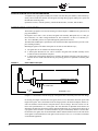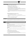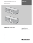
1
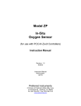
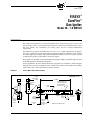
® SF-100 APRIL 19, 2013 FIREYE ® SureFire™ Gas Igniter Model 20 - 1.0 MBTUH DESCRIPTION The SureFire™ gas igniters are a versatile and reliable source of ignition energy for oil, coal, or natural gas burners. They are self-contained units and feature a stable and clean-burning flame, repeatable fuel ignition, low maintenance (no moving parts), and low cooling-/combustion-air requirements. The SureFire™ gas igniters are NFPA-rated as a Class 1, 2, or 3 igniter, depending on the application: Class 1 igniters are used for burner light-up and support under any conditions; Class 2 igniters are used for light-up and support under prescribed light-off conditions; and Class 3 igniters are used for light-up only and are not intended for warm-up or support. These igniters are provided with a durable High Energy Igniter (HEI) for repeatable light-off. Refer to the HEI bulletin for detailed HEI information. In most applications, the self-contained SureFire™ gas igniters are mounted in a burner through a mounting tube. The major components of the SureFire™ gas igniters are the guide tube assembly, and the HEI. Figure 1 shows the SureFire™ igniter assembly. FIGURE 1. SureFire Model 20 Gas Igniter Assembly DIMENSIONS mm (in) TO HEI CONNECTING CABLE HEI SPARK ROD ASSEMBLY SIGHT PORT 74.7 (2.94) REF QUICKRELEASE FLANGE CLAMP “L” REF 1.69 REF GUIDE TUBE GAS PILOT ORIFICE BAFFLE PLATE 1/2" NPT GAS HOSE CONNECTION 153.9 (6.06) REF HEI SPARK ROD TIP MUST BE FLUSH WITH FURNACE SIDE OF BAFFLE PLATE COMBUSTION COOLING AIR HOSE CONNECTION 3/4" NPT 47.8 (1.88) O.D. REF GAS TUBE DIMENSIONS IN MM (INCHES) 1 TABLE OF CONTENTS DESCRIPTION ............................................................................................... 1 TABLE OF CONTENTS ................................................................................ 2 DESCRIPTION (continued)............................................................................ 3 SPECIFICATIONS.......................................................................................... 3 SUREFIRE IGNITER SPECIFICATION PROCEDURE .............................. 4 SUREFIRE MODEL 20 GAS IGNITER........................................................ 4 SUREFIRE 20 ORDERING INFORMATION............................................... 7 SAFETY.......................................................................................................... 9 INSTALLATION............................................................................................. 9 COMMISSIONING ...................................................................................... 11 OPERATION................................................................................................. 12 TROUBLESHOOTING ................................................................................ 13 MAINTENANCE.......................................................................................... 13 STORAGE..................................................................................................... 14 SUREFIRE MODEL 20 OUTPUT CURVE................................................. 14 2 ® DESCRIPTION (continued) Guide Tube Assembly The guide tube assembly contains the working parts of the igniter and houses the gas transport tube, baffle, and HEI spark rod. Gas is transported down the guide tube through the gas transport tube and is distributed to the primary combustion zone. A small orifice upstream of the baffle releases a small amount of gas to mix with the cooling/combustion air. Cooling/combustion air is transported down the guide tube and mixes with the gas at the baffle plate to form a combustible mixture. Ignition first occurs at the spark tip and then spreads to the gas transport tube opening at the tip end of the igniter. Combustion is completed 2 to 3 feet into the furnace. Mounting Tube (optional) The mounting tube (Figure 4) is welded to the burner front plate in most cases, and supports the igniter assembly. The igniter guide tube slides into the mounting tube and is secured in place by a split clamping ring (squeeze collar), which is bolted to the mounting tube. The squeeze collar also acts as a packing gland follower. High Energy Igniter (HEI) The HEI spark rod provides a 12-joule spark, which ignites the gas/air mixture. The HEI consists of a fouling-resistant surface gap spark tip connected to a positioning rod, power unit, and cable. (See HEI bulletin for details.) View Port An integral view port is provided on the head of the SureFire™ igniter. SPECIFICATIONS SUREFIRE 20 Fuel Natural gas/propane Guide Tube OD 1.88” Mounting Tube OD 2.13” Capacity Rating (MBTU/hr.) 1.0 Fuel Supply Requirements (psig) 10 psig Cooling/Combustion Air Supply 12 SCFM@3”> windbox Cooling/Combustion Air Pressure (inches w.c. measured at the sight port) 0.5 Cooling/Combustion Air Connection 3/4” NPT, female Cooling/Combustion Air Pressure Measurement Port 1/8” NPT, female Material of Construction 304 Stainless Steel (except for gas transport tube and HEI Rod). Ignition Method High Energy Igniter (HEI), 12 joule NFPA Class 1, 2, or 3 Recommended Gas Hose Size 3/4” Gas Hose Connection 1/2” NPT, female Gas Line Strainer (FNPT) 0.33” 3 SUREFIRE IGNITER SPECIFICATION PROCEDURE A complete Fireye gas igniter assembly will consist of at least three part numbers, each ordered separately. These include the SureFire 20 Gas Igniter, the High Energy Igniter (HEI) power pack, and the HEI interconnecting cable. Optional accessories, ordered separately, include the Mount Tube, Air Hose, and Gas Hose. SUREFIRE MODEL 20 GAS IGNITER The SureFire gas Igniter is sized to fire natural gas with an output of 1.0MBTU/hr at a pressure of 10 psig (690 millibars). Each igniter comes with a 1.88" (48 mm) OD guide tube assembly, HEI spark rod, 1/2" NPT gas inlet connection, 3/4" NPT cooling/combustion air inlet connection. Air flow of 12 SCFM @ 3" W.C. above Windbox pressure is required through the guide tube at all times The HEI cable and HEI power pack must be selected from the HEI component list to provide a complete working assembly. Mounting the igniter to the burner front plate can be done several different ways; 1. 2. 3. FIGURE 2. The guide tube can be welded to the burner front plate. A mount plate fabricated on site, can be welded to the guide tube and that assembly can be welded or bolted to the burner front plate. A mount tube with packing gland can be welded to the burner front plate. Then the igniter is inserted into the mount tube and allowing the packing gland to be tightened around the guide tube. SureFire Model 20 Gas Igniter L FRONT PLATE 14” (350) Min DIMENSIONS in (mm) Length “L” is the distance from the firing tip of the igniter back to the break point of the rear flange. In selecting the length of the SureFire Gas Igniter, there are two dimensions that make up the total length of the igniter. One is the distance from the firing tip back to the burner frontplate, and the second is the distance from the burner front plate back to the rear flange. The total of these two distances will equal dimension “L” of the igniter. The first dimension is dependent on the burner size and must be measured or taken from a burner dimensional drawing. As a general rule the firing tip of a gas igniter can be located 6" (153mm) behind the oil gun. If a bluff body diffuser is used to stabilize the flame, the igniter must be mounted flush with the diffuser/stabilizer. Refer to the chart below for the igniter set back dimensions. This igniter can be used in a Class 1, 2 or 3 in either a continuous or intermittent application. 4 ® Table 1: GAS IGNITER SET BACK DIMENSIONS IN INCHES (Distance from Oil Gun Tip) IGNITER CLASS NO OIL GUN STABLIZER - IN (MM) SWIRLER TYPE STABLIZER - IN (MM) BLUFF BODY DIFFUSER- IN (MM) 1 6 (153) 0 0 2 6 (153) 0 0 3 6 (153) 6 (153) 0 Select a length “L” that will allow a minimum of 6" (153 mm) from the burner front plate back to the rear flange. MOUNT TUBE (Optional) Mount tube, 2.13" (54 mm) OD, carbon steel, with packing gland and locking collar, suitable for welding to the burner front plate. The mount tube is optional equipment and is not required unless the owner intends to periodically remove the complete igniter from the burner front. GAS HOSE (Optional) Fireye can provide a flexible stainless steel hose, 0.5" (13 mm) ID, with single braid stainless steel jacket, a 0.5" (13 mm) NPT nipple connection to igniter and a 0.75" (19 mm) NPT nipple connection to the gas supply. AIR HOSE (Optional) Fireye can also provide a reinforced 1" ID rubber air hose with a 1" NPT nipple connection to air supply at one end, and hose clamps at both ends. The air hose is required to supply cooling/combustion air to the igniter. 5 FIGURE 3. SureFire 20 GAS IGNITER 14” (350mm) Min CLOSE NIPPLE P/N 35-309 GASKET P/N 29-403 CLAMP P/N 13-382 SUREFIRE 20 P/N SF20-XXX 2.13” (55mm)Dia BURNER FRONT PLATE AIR HOSE 10’ (3.0m) P/N 59-495 MOUNT TUBE P/N MT20 -XX (OPTIONAL) 8” (203mm) or 27” (685mm) QUICK DISCONNECT PLUG P/N 10- 211 PRESSURE TESTER P/N 148- 21 QUICK DISCONNECT SOCKET P/N 9-438 SPARK TIP Short 8” P/N 145-18 *Long 27” P/N 145-19 *(used with gas igniters 38” and longer) GAS HOSE 4’ (1.2m) P/N GH20-04 6’ (1.8m) P/N GH20-06 8’ (2.4m) P/N GH20-08 8”(203mm) CABLE 15’ (4.5m) P/N SF1-CA1-15* 10” (250mm) *Refer to ORDERING INFORMATION, page 7, for list of available lengths POWER PACK P/N SF1-1 (110 VAC NEMA 4) P/N SF1-2 (220 VAC NEMA 4) P/N SF1-3 (110 VAC NEMA 4X) P/N SF1-4 (220 VAC NEMA 4X) 6 ® SUREFIRE 20 ORDERING INFORMATION Referring to Figures 2 and 3 and Part Number listings: 1. 2. 3. 4. Select the appropriate igniter length. Select optional SureFire gas igniter accessories. Select the appropriate HEI Power Pack (See page 8). Select the appropriate HEI Interconnecting Cable (See page 8). 1. SELECT THE APPROPRIATE SUREFIRE 20 GAS IGNITER The gas igniter part number will start with “SF20”, followed by three digits specifying the igniter length (in inches) available in two inch increments from 14” (014”) to 180” (180”). SF20 – XXX Length in inches (014 through 180) in 2” increments Fireye SureFire 20 gas igniter EXAMPLE: Specify a SureFire 20 gas igniter - 72 inches long : Specify part number: SF20 – 072 2. SELECT OPTIONAL ACCESSORIES PART NUMBER SUREFIRE 20 MOUNTING TUBES MT20-004 Mount Tube 4” long (igniter lengths 014 through 020) MT20-012 Mount Tube 12” long (igniter lengths 022 through 030) MT20-022 Mount Tube 22” long (igniter lengths 032 through 040) MT20-032 Mount Tube 32” long (igniter lengths 042 through 050) MT20-042 Mount Tube 42” long (igniter lengths 052 through 060) MT20-052 Mount Tube 52” long (igniter lengths 062 through 070) MT20-062 Mount Tube 62” long (igniter lengths 072 through 080) MT20-072 Mount Tube 72” long (igniter lengths 082 through 090) MT20-082 Mount Tube 82” long (igniter lengths 092 through 100) MT20-092 Mount Tube 92” long (igniter lengths 102 through 110) MT20-102 Mount Tube 102” long (igniter lengths 112 through 120 MT20-112 Mount Tube 112” long (igniter lengths 122 through 130) MT20-122 Mount Tube 122” long (igniter lengths 132 through 140) MT20-132 Mount Tube 132” long (igniter lengths 142 through 150) MT20-142 Mount Tube 142” long (igniter lengths 152 through 160) MT20-152 Mount Tube 152” long (igniter lengths 162 through 170) MT20-162 Mount Tube 162” long (igniter lengths 172 through 180) PART NUMBER SUREFIRE 20 GAS HOSE GH20-04 Gas Hose, 1/2” flexible stainless steel braid, 3/4” (NPT) x 4 foot GH20-06 Gas Hose, 1/2” flexible stainless steel braid, 3/4” (NPT) x 6 foot GH20-08 Gas Hose, 1/2” flexible stainless steel braid, 3/4” (NPT) x 8 foot 7 PART NUMBER 59-495 Air Hose, flexible rubber, 1”(I.D.) with 1” nipple, x 10 feet (cut to length on site) 35-309 Close nipple, 1/2” NPT stainless steel 10-211 Quick Disconnect Plug, male, 1/2” NPT 148-21 In-Line Pressure Tester (fuel gas) 9-438 Quick Disconnect Socket, female, 1/2” NPT PART NUMBER 3. Rear Flange Clamp 29-403 Rear Flange Gasket 145-18 Spark Tip, 8” (used with igniter lengths 036 and shorter) 145-19 Spark Tip, 27” (used with igniter lengths 038 and longer) SELECT THE APPROPRIATE HEI POWER PACK DESCRIPTION SF1-1 SureFire HEI Power Pack, 110 vac, NEMA 4 (painted steel) SF1-2 SureFire HEI Power Pack, 220 vac, NEMA 4 (painted steel) SF1-3 SureFire HEI Power Pack, 110 vac, NEMA 4X (stainless steel) SF1-4 SureFire HEI Power Pack, 220 vac, NEMA 4X (stainless steel) SELECT THE APPROPRIATE HEI INTERCONNECTING CABLE PART NUMBER 8 SUREFIRE 20 REPLACEMENT/SPARE PARTS 13-382 PART NUMBER 4. SUREFIRE 20 AIR HOSE AND GAS LINE ACCESSORIES DESCRIPTION SF1-CA1-06 SureFire HEI interconnecting cable with connectors, 6 feet long SF1-CA1-09 SureFire HEI interconnecting cable with connectors, 9 feet long SF1-CA1-12 SureFire HEI interconnecting cable with connectors, 12 feet long SF1-CA1-15 SureFire HEI interconnecting cable with connectors, 15 feet long SF1-CA1-20 SureFire HEI interconnecting cable with connectors, 20 feet long SF1-CA1-25 SureFire HEI interconnecting cable with connectors, 25 feet long SF1-CA1-50 SureFire HEI interconnecting cable with connectors, 50 feet long ® SAFETY Safety is the responsibility of each individual who installs, operates or maintains Fireye equipment. Fireye includes personnel safety as a basic design element of the SureFire igniter. Observe the following safety instructions prior to performing installation, operation, or maintenance: WARNING: Hazardous voltage is present and serious injury can occur. See HEI bulletin SF-1. 1. Use this equipment only for its intended purpose. 2. Follow only the installation, operation, and maintenance procedures discussed in this publication and on appropriate drawings. 3. Ensure that all electrical apparatus used to perform work on this equipment is in good working order and has been calibrated correctly. 4. Do not lift or disconnect grounding cables/wires while equipment is energized. 5. Do not perform modifications on this equipment. 6. Before opening the HEI power unit's hinged cover, disconnect the electrical supply from the box. Allow at least 2 minutes for the capacitor to discharge. Exercise extreme care when the power unit cover is open. Refer to the HEI Service Manual for complete safety instructions for HEI equipment. 7. Ensure that no voltage is present prior to disconnecting terminations. 8. Adhere to safety-related information on all drawings. 9. Close the manual fuel shutoff valves before performing maintenance or troubleshooting procedures. 10. Test all fuel gas pipe connections for leaks. 11. The HEI power pack enclosure and the igniter guide tube should be grounded. (See HEI bulletin SF-1 for details.) 12. When removing the igniter assembly from an operating furnace, wear protective clothing and insulated gloves. While observing the igniter flame through an open observation port, wear a face shield and protective clothing. WARNING: Only knowledgeable and qualified technicians should be allowed access to this system or to its components. The installation, maintenance, and operation of electronic equipment entails several elements of danger. Carelessness can result in serious injury or death from electrical shock, falls, or improper use of tools and test equipment. INSTALLATION A detailed description of the SureFire™ gas igniter installation follows. For job-specific installation instructions, refer to the appropriate arrangement and installation drawings. During installation, protect terminal boxes, spark rods, surfaces, round tubes, or any other protruding devices from accidental bumps or bending forces. The design of the SureFire™ gas igniter allows the user to weld the guide tube directly to the burner front plate, if desired. With this configuration, no mount tube is required. When welding the guide tube to the burner front plate, position the SureFire™ tip 3 inches behind the burner fuel vertical plane, as a general rule. The igniter guide tube is stainless steel; therefore, a stainless weld procedure is required. Optional Mounting Tube The mounting tube (Figure 4) is affixed permanently to the burner front plate and supports the igniter assembly. If a suitable mounting tube is not available, one must be installed. However, many retrofit installations may have a suitable mounting tube. The inside diameter of an existing mounting tube must provide adequate sliding clearance from the outside diameter of the guide tube, in order to prevent binding of the igniter during installation. In cases where a mounting tube must be installed, perform the following steps. 9 1. 2. 3. 4. Cut a hole in the burner front plate in the location desired or as indicated on the installation drawing. The diameter of the hole should be slightly larger than the outer diameter of the mounting tube. Insert the mounting tube through the front plate and into the burner area. Position the mounting tube to the correct distance and angle shown on the installation drawing. Seal-weld the mounting tube to the burner front plate using a 6011 weld rod (carbon steel to carbon steel) with a full penetration weld. On some older installations where cast iron plates must be penetrated, a steel flange or cover plate can be bolted to the cast iron, so that the mounting tube can be welded to that flange or plate. When installing the guide tube, avoid contact with internal burner parts, such as air vanes or burner sleeves. Occasionally, air vanes may have to be trimmed in order to provide clearance for the mounting tube. On the mounting tube, loosen packing and clamping nuts, so the guide tube slides easily into the mounting tube. Guide Tube Assembly 1. 2. 3. FIGURE 4. Before installing the guide tube assembly into the mounting tube, inspect the primary combustion area for cleanliness and proper HEI spark rod position. The HEI spark rod is factory set and should not need adjustment. If necessary, refer to Figure 6 for HEI spark rod tip settings. WHEN THE PRECEDING INSPECTION IS COMPLETE, SLIDE THE SUREFIRE™ guide tube assembly into the mounting tube. If necessary, apply a thin coat of high-temperature-resistant lubricant to the outside surface of the guide tube to assist with sliding it through the squeeze collar. POSITION THE SUREFIRE™ igniter assembly to the depth shown on the burner installation drawing. During replacement applications, insert the furnace end of the SureFire™ guide tube assembly to the same location as the previous igniter. As a general rule, locate the SureFire™ tip 3 inches behind the burner fuel nozzle vertical plane. Typical SureFire 20 Mounting Tube CLAMPING COLLAR MATERIAL: CARBON STEEL, RED PRIMER PAINTED 12.7 (.50) 54.1 (2.13) 74.7 DIA (2.94) 19.1 (.75) L DIMENSIONS IN MM (INCHES) 1503 Fuel and Air Piping 1. To prevent contamination of the igniter during commissioning, ensure that all fuel and air piping and flexible hoses have been blown free of any debris or moisture. During installation, tapping off the gas header from the top or side also prevents contamination. NOTE: Equal gas flow and pressure distribution to each igniter are important for reliable and efficient operation of the igniter. Care should be exercised in the design, especially on multiple igniter/burner furnaces, to achieve even distribution under all flow conditions. Good engineering practice recommends limiting the line velocities of gas fuel to a maximum of 9000 ft./min. 2. Install gas pressure regulators with the required turndown capacity and response time capability, in the gas headers to ensure that the specified gas pressure is maintained at the igniter. CAUTION: Design and install flexible hoses to allow for maximum boiler expansion. 3. 10 Connect the flexible gas hose from the supply piping to the corresponding connection on the SureFire™ igniter. Install the flexible hose with all of the bends in one plane. The hose cannot withstand twisting or kinking; if necessary, install an additional union. ® 4. 5. FIGURE 5. Before tightening the mounting tube squeeze collar, rotate the guide tube, as necessary, to accept the cooling/combustion air flexible hose connection. Connect the cooling/combustion air flexible hose to the SureFire™ guide tube. Typical HEI Spark Rod Tip Location IGNITER GUIDE TUBE HEI SPARK TIP POSITIONED EVEN WITH BAFFLE PLATE GAS PILOT ORIFICE BAFFLE PLATE GAS TRANSPORT TUBE Wiring Consult the control system wiring diagram for site-specific wiring connections. The SureFire™ igniter requires ac service to the HEI power unit and AC or DC service to the block and vent valve solenoid(s) and block valve position switch (if applicable). Before commissioning the equipment, test all electrical components for proper operation by energizing the component while it is isolated from the system. Improper operation or failure of a component to operate requires troubleshooting techniques, such as performing a continuity check, locally energizing the component, or temporarily bypassing the interlock. Keep accurate records of all electrical tests. Before proceeding with commissioning, all interlocks must be restored to operating condition. COMMISSIONING Before commissioning the SureFire™ igniter, complete all of the steps listed in the Installation section of this manual. Use the following checklist to ensure that the SureFire™ igniter is ready for initial operation. • • • The fuel and air piping configuration is correct, and dampers, valves, strainers, and instrumentation are installed properly. The air and gas connections to the guide tube are installed according to the preceding instructions or the installation drawings (if provided). All electrical components are wired properly and tested, including the HEI power unit and spark rod assembly. To commission the SureFire™ igniter, complete the above checklist and then perform the following steps: 1. 2. 3. 4. 5. Remove the 1/8" NPT pipe plug near the observation port and connect a manometer. Place the cooling/combustion air system into service by starting the cooling/combustion air fan(s) and opening the isolation valves. Adjust the cooling/combustion air manual valve to approximately 0.5 inch w.c. above furnace pressure, as measured at the rear flange. Alternately, use an air flow measuring device to measure and adjust for approximately 12 SCFM flow. When the 0.5 inch w.c. or 12 SCFM pressure is set, remove the manometer and replace the 1/8" NPT pipe plug. Prepare to place the SureFire™ igniter in service by setting the igniter gas header pressure regulator to the pressure required at the igniter gas connection. (Installing a temporary test gauge at the igniter helps to observe fuel pressure while performing proceeding step. 11 NOTE: Before proceeding, all “light-off” permissive conditions must be satisfied. 6. 7. Initiate a start command to the SureFire™ igniter while observing the fuel pressure. The SureFire™ igniter ignites within 10 seconds from the time the fuel valve opens. The base of the flame should be blue and may change to a bright yellow as the flame travels into the furnace. 8. If the SureFire™ igniter fails to ignite, or the flame pattern is not as described in step 6, refer to the Troubleshooting section. 9. Initiate a shutdown command to the SureFire™ igniter. 10. Repeat the start and shutdown procedures of steps 6 and 8 above to demonstrate repeatability. Once the SureFire™ igniter has been commissioned and adjustments have been optimized, the igniter provides trouble-free operation as long as normal maintenance procedures are practiced, as outlined in the Maintenance section. OPERATION The SureFire™ igniter is ready for normal operation after the installation and commissioning procedures have been completed. To place the SureFire™ igniter into service from a cold state, proceed as follows: 1. 2. 3. 4. 5. Prepare the boiler for light-off by satisfying all light-off permissives. Start the cooling/combustion air fan(s) or open air path from other source. These fans must remain in service while the boiler is in operation, unless alternate means of cooling the igniter tip is provided. Prepare the igniter gas supply and header system to allow pressure to the individual igniter block valves. Set the igniter fuel regulator to the specified pressure. Initiate an igniter start. The following sequence of events occurs as the SureFire™ igniter goes into service. — The HEI is energized and starts to spark. — The gas double block valve opens and the vent valve closes admitting fuel to the igniter. — Ignition occurs within approximately 5 seconds of the fuel admission. — The flame detector detects flame 8 to 10 seconds from the start of the start signal initiation, if applicable. — The HEI is de-energized and stops sparking. If an igniter flame is not detected within 10 seconds, the igniter block valves are closed, the igniter trip is initiated, and the HEI is de-energized. On a manually controlled igniter system, the time limits discussed previously in step 5 still apply. However, the operator must initiate shutdown of the fuel flow to the igniter, if an igniter flame is not detected within approximately 10 seconds. To place SureFire™ igniters in service on an operating boiler, follow preceding steps 3 through 5. To remove SureFire™ igniter from service, either manually or automatically, follow these steps: 1. 2. 12 Initiate an igniter STOP command. The following sequence of events occurs: — The gas block valves close, and the vent valve opens. — The HEI power unit is deenergized (if energized). — The SureFire™ igniter extinguishes and is ready for the next operating cycle. Close the igniter main gas trip valve, if the igniters will not be needed for an extended period of time. ® TROUBLESHOOTING If the igniter does not light, check the following: • • • • • • • All fuel supply valves, including manual valves, are open. Regulated gas pressure is available to the igniter. Any valves in the gas lines are functioning properly. Proper cooling/combustion air pressure is maintained at the igniter. HEI spark rod is operating correctly and installed in the proper position, as shown in Figure 6. If the HEI doesn't operate correctly, ensure that the spark tip is not grounded externally. (If the HEI does not operate correctly, refer to the HEI bulletin SF-1.) Ensure that necessary voltage is being received at low voltage terminals on the HEI power unit. Both primary jet and gas transport tube orifice are free of foreign material. (See Maintenance section.) If the igniter lights but fails to stay on, check the following: • Fuel pressure is maintained as igniter starts. • Cooling/combustion air flow is set properly and is maintained as igniter starts. Burner air flow is not blowing out the flame or not blowing the flame away from the detector sighting. Flame detector is functioning properly, if applicable. Flame detector is sighted properly, if applicable. • • • MAINTENANCE The SureFire™ components discussed below require maintenance. Proper care of these components ensures long and reliable service. On a periodic basis, complete preventive maintenance activities. CAUTION: Use protective clothing and gloves if furnace is in operation. Guide Tube Inspect the guide tube from the furnace side or remove internals from the mounting tube every 12 months or during a planned boiler outage. NOTE: If heat distortion is observed, the cooling airflow to SureFire igniter can be impaired in some way, or the igniter may be too far forward. Refer to the Commissioning section and make the necessary adjustments to the cooling/combustion air flow and igniter position. Orifice Tube The following procedure is recommended maintenance steps for the orifice tube and dump tube orifice. 1. 2. 3. 4. 5. 6. Close the manual valve to shut off the gas to the igniter, and then disconnect gas line from igniter. Remove HEI spark rod electrical connections. Remove the guide tube clamp from the rear flange. Carefully remove the internals of the igniter from guide tube. Unscrew the gas transport tube and remove the orifice for cleaning. To prevent scoring the orifice, clean any debris or dirt that has collected on the orifice by using a soft wire. 13 7. 8. 9. Using compressed air to clean the tip, blow out the gas lines, both forward and backward. Inspect and clean the primary orifice located upstream of the removable fixed orifice. Replace the removable orifice in its original location. High Energy Igniter Remove and inspect the spark rod assembly every 6 months or during planned boiler outage, per the HEI Service Manual. Combustion Air Fan and Motor Set Every 6 months, ensure that igniter is receiving adequate air flow. STORAGE Store the SureFire™ igniter in a clean, dry atmosphere. When possible, store the assembly in its original shipping container until used. If the SureFire™ igniter is removed from its shipping container, store it in a horizontal position supported at both ends of the guide tube. Protect both guide tube ends from damage due to inadvertent bumps or blows. Cover the SureFire™ igniter with plastic to keep it free of dust and dirt. Storage longer than 30 days requires humidity less than 85% and temperature less than 120°F. FIGURE 6. 14 SureFire Model 20 Gas Igniter Output Curve ® 15 NOTICE When Fireye products are combined with equipment manufactured by others and/or integrated into systems designed or manufactured by others, the Fireye warranty, as stated in its General Terms and Conditions of Sale, pertains only to the Fireye products and not to any other equipment or to the combined system or its overall performance. WARRANTIES FIREYE guarantees for one year from the date of installation or 18 months from date of manufacture of its products to replace, or, at its option, to repair any product or part thereof (except lamps, electronic tubes and photocells) which is found defective in material or workmanship or which otherwise fails to conform to the description of the product on the face of its sales order. THE FOREGOING IS IN LIEU OF ALL OTHER WARRANTIES AND FIREYE MAKES NO WARRANTY OF MERCHANTABILITY OR ANY OTHER WARRANTY, EXPRESS OR IMPLIED. Except as specifically stated in these general terms and conditions of sale, remedies with respect to any product or part number manufactured or sold by Fireye shall be limited exclusively to the right to replacement or repair as above provided. In no event shall Fireye be liable for consequential or special damages of any nature that may arise in connection with such product or part. FIREYE Derry, New Hampshire 03038 USA www.fireye.com 16 APRIL 19, 2013 Supersedes October 24, 2007