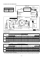
1
FILE NO. A05-001
SERVICE MANUAL
SPLIT TYPE
<NEW DIGITAL INVERTER>
OUTDOOR UNIT
RAV-SM561AT-E
RAV-SM801AT-E
RAV-SM1101AT-E
RAV-SM1401AT-E
INDOOR UNIT
This Service Manual describes contents of the new outdoor unit.
For the indoor unit, refer to the Service Manual with FILE NO. A03-003F.
R410A
PRINTED IN JAPAN, Apr.,2005 ToMo
ADOPTION OF NEW REFRIGERANT
This Air Conditioner is a new type which adopts a new refrigerant HFC (R410A) instead of the conventional
refrigerant R22 in order to prevent destruction of the ozone layer.
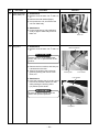
WARNING
Cleaning of the air filter and other parts of the air filter involves dangerous work in high places, so be sure to
have a service person do it. Do not attempt it yourself. The cleaning diagram for the air filter is there for the
service person, and not for the customer.
CONTENTS
1. SPECIFICATIONS ........................................................................................................... 3
2. CONSTRUCTION VIEWS (EXTERNAL VIEWS) ............................................................. 5
3. REFRIGERATING CYCLE DIAGRAM ............................................................................ 8
4. WIRING DIAGRAM ....................................................................................................... 11
5. SPECIFICATIONS OF ELECTRICAL PARTS ............................................................... 12
6. REFRIGERANT R410A ................................................................................................. 13
6-1.
6-2.
6-3.
6-4.
6-5.
Safety During Installation/Servicing ................................................................................ 13
Refrigerant Piping Installation ....................................................................................... 13
Tools ................................................................................................................................... 17
Recharging of Refrigerant ................................................................................................ 18
Brazing of Pipes ................................................................................................................ 19
7. CONTROL SPECIFICATIONS ...................................................................................... 21
7-1. Outdoor Controls .............................................................................................................. 21
7-2. Outline of Main Controls ................................................................................................... 24
8. TROUBLESHOOTING .................................................................................................. 29
8-1.
8-2.
8-3.
8-4.
8-5.
8-5.
Summary of Troubleshooting ........................................................................................... 29
Check Code List ................................................................................................................ 31
Error Mode Judgment by LED Display of Outdoor Unit ................................................ 34
Contents of Error Display ................................................................................................. 35
Troubleshooting Procedure for Each Check Code ......................................................... 36
Other Function ................................................................................................................... 57
9. DETACHMENTS ............................................................................................................ 58
10. EXPLODED VIEWS AND PARTS LIST ........................................................................ 73
–2–
1. SPECIFICATIONS
RAV-SM561AT-E, RAV-SM801AT-E
Model name
RAV-SM561AT-E
RAV-SM801AT-E
Appearance
Silky shade (Muncel 1Y8.5/0.5)
Power supply
1 phase 230 V (220 – 240 V) 50 Hz
(Power exclusive to outdoor is required.)
Type
Compressor
Hermetic compressor
Motor
(kW)
1.1
1.6
Pole
4 poles
Refrigerant charged
(kg)
R410A 1.0
Refrigerant control
Pulse motor valve
Standard length
Max. total length
Pipe
R410A 1.7
20 (without additional charge)
(m)
30
Over 20m
Add 20 g/m (Max. 200 g)
Add 40 g/m (Max. 400 g)
(m)
30
Outdoor higher (m)
30
Outdoor lower
Height difference
Outer dimension
Height
(mm)
550
Width
(mm)
780
Depth
(mm)
290
Total weight
(kg)
38
42
Heat exchanger
Finned tube
Fan
Fan unit
Standard air flow High
Motor
Propeller fan
(m³/h)
2400
2700
(W)
43
Gas side
(mm)
Ø12.7 (1/2”)
Ø15.9 (5/8”)
Liquid side
(mm)
Ø6.4 (1/4”)
Ø9.5 (3/8”)
Connecting pipe
Discharge temp. sensor
Over-current sensor
Compressor thermo.
Protection device
Sound level
(Note 2)
High (Mid./Low)
(Cooling/Heating)
(dB•A)
46 / 48
48 / 50
Note 1 : The cooling capacities and electrical characteristics are measured under the conditions speciied by JIS B 8616 based
on the reference piping 7.5m.
Note 2 : The sound level is measured in an anechoic chamber in accordance with JIS B8616. Normally, the values measured in
the actual operating environment become larger than the indicated values due to the effects of external sound.
Note : Rated conditions
Cooling : Indoor air temperature 27°C DB/19°C WB, Outdoor air temperature 35°C DB
Heating : Indoor air temperature 20°C DB, Outdoor air temperature 7°C DB/6°C WB
–3–
RAV-SM1101AT-E, RAV-SM1401AT-E
Model name
RAV-SM1101AT-E
RAV-SM1401AT-E
Appearance
Silky shade (Muncel 1Y8.5/0.5)
Power supply
1 phase 230 V (220 – 240 V) 50 Hz
(Power exclusive to outdoor is required.)
Type
Compressor
Hermetic compressor
Motor
(kW)
Pole
3.0
4 poles
Refrigerant charged
(kg)
Refrigerant control
R410A 2.8
Pulse motor valve
Standard length
Max. total length
Pipe
2.5
30 (without additional charge)
(m)
50
Over 20m
Add 40 g/m (Max. 800 g)
(m)
30
Outdoor higher (m)
30
Outdoor lower
Height difference
Outer dimension
Height
(mm)
795
Width
(mm)
780
Depth
(mm)
320
(kg)
77
Total weight
Heat exchanger
Finned tube
Fan
Fan unit
Standard air flow High
Propeller fan
(m³/h)
4500
(W)
100
Gas side
(mm)
Ø15.9 (5/8”)
Liquid side
(mm)
Ø9.5 (3/8”)
Motor
Connecting pipe
Discharge temp. sensor
Over-current sensor
Compressor thermo.
Protection device
Sound level
(Note 2)
High (Mid./Low)
(Cooling/Heating)
(dB•A)
53 / 54
Note 1 : The cooling capacities and electrical characteristics are measured under the conditions speciied by JIS B 8616 based
on the reference piping 7.5m.
Note 2 : The sound level is measured in an anechoic chamber in accordance with JIS B8616. Normally, the values measured in
the actual operating environment become larger than the indicated values due to the effects of external sound.
Note : Rated conditions
Cooling : Indoor air temperature 27°C DB/19°C WB, Outdoor air temperature 35°C DB
Heating : Indoor air temperature 20°C DB, Outdoor air temperature 7°C DB/6°C WB
–4–
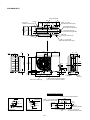
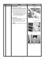
2. CONSTRUCTION VIEWS (EXTERNAL VIEWS)
RAV-SM561AT-E
Drain hole (Ø25)
60
108
90
125
2-Ø11-14 U-hole
(For Ø8–Ø10 anchor bolts)
54
Connecting pipe port
(Flare Ø12.7 at gas side)
290
Connecting pipe port
(Flare Ø6.4 at liquid side)
30
8-Ø6 hole
(For fixing outdoor unit)
20
306
Ø6 hole pitch
320
(Anchor bolt long
hole pitch)
A legs
Drain hole
(2-Ø20 × 88 long hole)
30
600
B legs
2-Ø11 × 14 long hole
(For Ø8–Ø10 anchor bolts)
21
483
147
257
157
108
79
145
449
31
52
35
8
500
342
71
780
Guard for air discharge
54
32
143
137
25
22
93
483
550
21
6
69.5
Charge port
Earth
terminal
4-Ø4.5 embossing (Ø4 STS used)
(For mounting air direction guide)
54
38
11
R15
2-Ø6 hole
38
320
R5.5
Details of A legs
2-Ø11 × 14 U-shape holes
(For Ø8–Ø10 anchor bolt)
R15
54
Product
external line
Anchor bolt mounting dimension
600
R5.5
150
or more
Product
external line
2-Ø6 hole
320
600
320
Space required for service
Suction port
300
or more
Suction
port
150 or more
(Minimum
distance up to wall)
600
500
or more
Details of B legs
–5–
Discharge
port
2-Ø11 × 14 long hole
(For Ø8–Ø10 anchor bolt)
RAV-SM801AT-E
Drain hole (Ø25)
60
108
90
125
2-Ø11–14 U-hole
(For Ø8–Ø10 anchor bolts)
54
Connecting pipe port
(Flare Ø15.9 at gas side)
290
Connecting pipe port
(Flare Ø9.5 at liquid side)
30
8-Ø6 hole
(For fixing outdoor unit)
20
306
Ø6 hole pitch
320
(Anchor bolt long
hole pitch)
A legs
Drain hole
(2-Ø20 × 88 long hole)
30
600
B legs
2-Ø11 × 14 long hole
(For Ø8–Ø10 anchor bolts)
21
483
147
257
157
108
79
145
449
31
52
35
8
500
342
71
780
Guard for air discharge
54
32
143
137
25
22
93
483
550
21
6
69.5
Charge port
Earth
terminal
4-Ø4.5 embossing (Ø4 STS used)
(For mounting air direction guide)
54
38
11
R15
2-Ø6 hole
38
320
R5.5
Details of A legs
2-Ø11 × 14 U-shape holes
(For Ø8–Ø10 anchor bolt)
R15
54
Product
external line
Anchor bolt mounting dimension
600
R5.5
150
or more
Product
external line
2-Ø6 hole
320
600
320
Space required for service
Suction port
300
or more
Suction
port
150 or more
(Minimum
distance up to wall)
600
500
or more
Details of B legs
–6–
Discharge
port
2-Ø11 × 14 long hole
(For Ø8–Ø10 anchor bolt)
Knockout
(For draining) Drain hole (Ø20 × 88 Burring hole)
Drain hole (Ø25 Burring hole)
29
90
191
20
Suction
Part B
17.5
21
40
26
40
Suction
port
21
43
(Long hole pitch
for anchor bolt)
40
70
Details of B part
Knockout
(For draining)
43
Part A
17.5
300
39
47
Discharge
port
60
150
40
Details of A part
95
900
Installation bolt hole
(Ø12 × 17 U-shape holes)
101
314
Handles
(Both sides)
Refrigerant pipe connecting port
(Ø9.5 Flare at liquid side)
565
Refrigerant pipe connecting port
(Ø15.9 Flare at gas side)
60
96
Z
Discharge guide
mounting hole
(4-Ø4 Embossing)
28
60 67
154
264
264
2
300
27
1
307
320
Knockout for lower piping
86 7
Z views
795
Space required for service
150
or more
2-Ø12 × 17 U-shape holes
(For Ø8–Ø10 Anchor bolt)
2
46
27
2
1
30
365
25
85
58
161
165
60 80
1
60 90
17.5
365
port
Installation bolt hole
(Ø12 × 17 U-shape holes)
58 7
17.5
RAV-SM1101AT-E, RAV-SM1401AT-E
600
Suction port
150
or more
150
or more
Discharge (Minimum
port
distance up to wall)
45
500
Discharge
or more
400
port
–7–
2-Ø12 × 17 long hole
(For Ø8–Ø10 Anchor bolt)
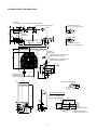
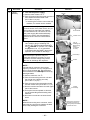
3. REFRIGERATING CYCLE DIAGRAM
RAV-SM561AT-E
Indoor unit
TCJ
sensor
Air heat exchanger
TC sensor
Outer diameter of refrigerant pipe
Gas side ØA
Liquid side ØB
12.7mm
6.4mm
Refrigerant pipe
at gas side
Ø12.7
Packed valve
Packed valve
Outer dia. ØA
Refrigerant pipe
at liquid side
Ø6.4
Packed valve
Outdoor unit
PMV
(Pulse Motor Valve)
(CAM-B30YGTF-1)
TS sensor
2-step muffler
Ø19.05 × 200L
Min. Max.
5m 30m
Packed valve
Outer dia. ØB
TO sensor
TD sensor
Strainer
4-way valve
(STF-0108Z)
TE
sensor
Heat exchanger
Ø8 ripple, 2 rows,
14 steps
FP1.3, flat fin
Muffler
Ø19 × L160
Rotary compressor
(DA150A1F-20F)
Distributor
Cooling
Heating
Pressure
(MPa)
Pipe surface temperature (°C)
(kg/cm²G) Discharge
Suction
Indoor/Outdoor
Compressor
temp. conditions
Indoor heat Outdoor heat revolutions per Indoor
(DB/WB) (°C)
exchanger exchanger
fan
second (rps)
(TD)
(TS)
(TC)
(TE)
*
9.9
85
14
12
48
70
HIGH
27/19
35/–
39.8
11.0
93
26
17
54
70
HIGH
32/24
43/–
0.70
19.4
7.1
48
7
5
30
50
LOW
18/15.5
–5/–
2.31
0.61
13.6
6.2
87
5
40
1
97
HIGH
20/–
7/6
Heating Overload
2.86
0.89
29.2
9.1
86
17
47
11
95
HIGH
28/–
24/18
Low load
1.86
0.25
19.0
2.6
69
–14
31
–15
98
HIGH
15/–
–10/(70%)
Pd
Ps
Pd
Standard
3.50
0.97
35.7
Cooling Overload
3.90
1.08
Low load
1.90
Standard
Ps
Indoor Outdoor
* 4 poles are provided to this compressor.
The compressor frequency (Hz) measured with a clamp meter is 2 times of revolutions (rps) of the compressor.
–8–
RAV-SM801AT-E
Indoor unit
TCJ
sensor
Air heat exchanger
TC sensor
Outer diameter of refrigerant pipe
Gas side ØA
Liquid side ØB
15.9mm
9.5mm
Refrigerant pipe
at gas side
Ø15.9
Packed valve
Refrigerant pipe
at liquid side
Ø9.5
Packed valve
Min. Max.
5m 50m
Pd
TS
sensor
Packed valve
Outer dia. ØA
2-step
muffler
Ø25 × 200L
TD
sensor
Outdoor unit
Packed valve
Outer dia. ØB
Ps
PMV
(Pulse Motor Valve)
(CAM-B30YGTF-1)
TO sensor
Strainer
TE
sensor
4-way valve
(STF-0213Z)
Heat exchanger
Ø8 ripple,
2 rows, 20 steps
FP1.3, flat fin
Accumulator
(1000cc)
Rotary
compressor
(DA150A1F-20F)
Distributor
Cooling
Heating
Pressure
(MPa)
Pipe surface temperature (°C)
(kg/cm²G) Discharge
Suction
Indoor/Outdoor
Compressor
temp. conditions
Indoor heat Outdoor heat revolutions per Indoor
(DB/WB) (°C)
exchanger exchanger
fan
second (rps)
(TD)
(TS)
(TC)
(TE)
*
8.8
84
11
10
45
83
HIGH
27/19
35/–
33.6
10.2
82
17
16
51
76
HIGH
32/24
43/–
0.83
18.9
8.5
42
8
6
23
35
LOW
18/15.5
–5/–
2.53
0.62
25.8
6.3
75
3
42
2
95
HIGH
20/–
7/6
Heating Overload
3.42
1.07
34.9
10.9
80
20
54
17
50
LOW
28/–
24/18
Low load
1.99
0.23
20.3
2.3
89
–19
34
–18
120
HIGH
15/–
–10/(70%)
Pd
Ps
Pd
Standard
3.28
0.86
33.4
Cooling Overload
3.59
1.00
Low load
1.85
Standard
Ps
Indoor Outdoor
* 4 poles are provided to this compressor.
The compressor frequency (Hz) measured with a clamp meter is 2 times of revolutions (rps) of the compressor.
–9–
SM801BT-E /
SM800AT-E, SM800UT-E,
SM800BT-E, SM800KRT-E
RAV-SM1101AT-E, RAV-SM1401AT-E
Indoor unit
Distributor
(Strainer incorporated)
TCJ sensor
Outer diameter of refrigerant pipe
Gas side ØA
Liquid side ØB
15.9mm
9.5mm
Strainer
Air heat exchanger
TC sensor
Refrigerant pipe
at gas side
Ø15.9
Ball valve
Cooling: Low pressure
Ball valve
Outer dia. ØA
Strainer
TS sensor
Refrigerant pipe
at liquid side
Ø9.5
Packed valve
Min. Max.
5m 50m
Packed valve
Outer dia. ØB
Outdoor unit
PMV
(Pulse Motor Valve)
(UKV-25D22)
TO sensor
TD sensor
4-way valve
(STF-0213Z)
Strainer
TE
sensor
Muffler
Heat exchanger
Outer side Ø8, 2 rows, 20 steps
Ø25 × L210 FP1.3, flat fin
Inner side Ø9.52, 1 row, 30 steps
Accumulator
Rotary
Ø25 × L180 FP1.5, flat fin
(2500cc)
compressor
(DA420A3F – 21M)
Distributor
Cooling
Heating
RAV-SM1101AT-E
Pressure
(MPa)
Pipe surface temperature (°C)
(kg/cm²G)
Discharge
Suction
(TD)
(TS)
Indoor/Outdoor
Compressor
Indoor heat Outdoor heat revolutions per Indoor temp. conditions
(DB/WB) (°C)
exchanger exchanger
fan
second (rps)
Pd
Ps
Pd
(TC)
(TE)
*
Standard
3.44
0.92
35.1
9.4
82
8
10
39
47
HIGH
27/19
35/–
Cooling Overload
3.73
1.18
38.1
12.0
82
15
17
48
42
HIGH
32/24
43/–
Low load
1.49
0.70
15.2
7.1
39
8
3
22
30
LOW
18/15.5
–5/–
Standard
2.80
0.61
28.6
6.2
80
0
46
1
48
HIGH
20/–
7/6
Heating Overload
3.43
1.08
35.0
11.0
82
14
55
13
24
LOW
30/–
24/18
Low load
2.20
0.25
22.4
2.6
76
–19
36
–16
55
HIGH
15/–
–10/(70%)
Ps
Indoor Outdoor
RAV-SM1401AT-E
Pressure
(MPa)
Pipe surface temperature (°C)
(kg/cm²G)
Discharge
Suction
(TD)
(TS)
Indoor/Outdoor
Compressor
Indoor heat Outdoor heat revolutions per Indoor temp. conditions
(DB/WB) (°C)
exchanger exchanger
fan
second (rps)
Pd
Ps
Pd
(TC)
(TE)
*
Standard
3.52
0.85
35.9
8.7
87
8
9
39
54
HIGH
27/19
35/–
Cooling Overload
3.78
1.12
38.6
11.4
84
15
17
47
45
HIGH
32/24
43/–
Low load
1.51
0.71
15.4
7.2
40
7
3
23
30
LOW
18/15.5
–5/–
Standard
2.88
0.60
29.4
6.1
85
1
47
1
61
HIGH
20/–
7/6
Heating Overload
3.41
1.08
34.8
11.0
81
14
54
13
24
LOW
30/–
24/18
Low load
2.35
0.24
24.0
2.4
80
–19
40
–16
73
HIGH
15/–
–10/(70%)
Ps
Indoor Outdoor
* 4 poles are provided to this compressor.
The compressor frequency (Hz) measured with a clamp meter is 2 times of revolutions (rps) of the compressor.
– 10 –
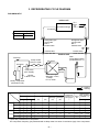
4. WIRING DIAGRAM
RAV-SM561AT-E, RAV-SM801AT-E
Compressor
CN300
RED P04
WHI P05
BLK P06
Q200~205
IGBT
P.C. Board
(MCC-5009)
R221
P25
YEL
BLK
WHI
RED
Fan motor
P24
R220
P23
YEL
P22
CN700
R219
P21
BRW
P20
P35
L03
YEL
Pulse motor valve
F03
Fuse
T3.15A
AC250V
C13
P34
L01 Varistor
CN603
TS
Surge absorber
C12 C14
(Suction pipe
Temp. sensor)
Varistor
CN602
Power relay
P19
DB02
CT
P18
P11
Reactor
TO
(Outdoor
Temp. sensor)
F01 Fuse
T25A, AC250V
P03 P10
ORN BLK
Relay
P02
WHI
CN601
TD
(Discharge pipe
Temp. sensor)
P08
CN600
TE
Q404
(Condensor pipe
Temp. sensor)
P32
P33
CN701
P30
P31
P7
BLK
PUR
Coil for
4-way valve
Reactor
Power supply
To
indoor unit 220-240V~,
50Hz
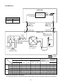
RAV-SM1101AT-E, RAV-SM1401AT-E
P18
BLU
P17
YEL
–
~
P20
P21 ORG
P24 BRW
P29
RED
~
F01 Fuse
T25A, 250V~
RY01
P.C. Board
(MCC-1438)
Power factor
control
CN03
CN09 RED
IGBT Module
CN02
CN10 WHI
CN11 BLK
W V U
CM
WHI
5 CN01
5 RED
PNK
RED
BLU
WHI
BLK
BLK
3
3
1 2 CN04
1 2 WHI
3 CN04 1 2 CN600
3 WHI 1 2 BLK
TS
1 2 3 4 5 CN800 CN03 1
1 2 3 4 5 RED WHI 1
3
3
TH
1
1
3
3
TE
TO
1 2
1 2
1 2
1 2
Compressor
TD
1
1
3
3
CN605 CN604 CN601 CN600
WHI
WHI WHI
WHI
WHI
RED
Power supply
220V~240V~,50Hz
BLK
ORN
FM
Fan motor
BLK
1 2 3 4 5
1 2 3 4 5
3 3
1 1
To indoor unit
– 11 –
1 2 CN500
1 2 BLU
Optional
P.C.Board
MCC-1522
49C
ORN
motor
PMV Pulse
valve
1 2 3 4 5 CN804
1 2 3 4 5 BLU
PNK
GRY
N
1 2 3 4 5 CN300
1 2 3 4 5 WHI
YEL
L
WHI
RED
3
1 2 3 4 5 6 7 8
CN801
CN700 YEL
RED
3 3
20SF Coil for 4-way valve
1 1
RED
SUB P.C. Board
(MCC-1531)
5 5
1 2 3 4 5 6 CN702 CN301 1 2 3
1 2 3 4 5 6 WHI
WHI 1 2 3
2
1
1
3 3
BLK
1
1 2 3 4 5 CN06
1 2 3 4 5 RED
BLU
1
1
1 2 CN05
1 2 WHI
YEL
CN02
BLK
1 1
RED
5 CN13
5 RED
ORN
3
3
PNK
1
1
RED
WHI
CN01
BLK
RED
~
+
1 2
1 2
P08 WHI
WHI
P09
P12 GRY
GRY
P13
1 2
1 2
P19
Reactor
P28 BLK
Reactor
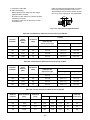
5. SPECIFICATIONS OF ELECTRICAL PARTS
RAV-SM561AT-E, RAV-SM801AT-E
Parts name
No.
Type
Specifications
1
Fan motor
ICF-140-43-4
Output (Rated) 43 W
2
Compressor
DA150A1F-20F
3 phase, 4P, 1100 W
3
Reactor
4
Outdoor temp. sensor (To-sensor)
—
10 kΩ at 25°C
5
Heat exchanger sensor (Te-sensor)
—
10 kΩ at 25°C
6
Suction temp. sensor (Ts-sensor)
—
10 kΩ at 25°C
7
Discharge temp. sensor (Td-sensor)
—
50 kΩ at 25°C
8
Fuse (Switching power (Protect))
T3.15 A, AC 250 V
9
Fuse (Inverter, input (Current protect)
25 A, AC 250 V
10
4-way valve solenoid coil
11
Compressor thermo. (Protection)
CH-57
10 mH, 16A
VHV-01AJ503C1
US-622
ON : 90 ± 5°C, OFF : 125 ± 4°C
RAV-SM1101AT-E, RAV-SM1401AT-E
Parts name
No.
1
Fan motor
2
Compressor
3
Reactor
4
Type
ICF-280-100-1
DA420A3F-21M
Specifications
Output (Rated) 100 W
3 phase, 4P, 3750 W
CH-56-2Z-T
6 mH, 18.5 A
Outdoor temp. sensor (To-sensor)
—
10 kΩ at 25°C
5
Heat exchanger sensor (Te-sensor)
—
10 kΩ at 25°C
6
Suction temp. sensor (Ts-sensor)
—
10 kΩ at 25°C
7
Discharge temp. sensor (Td-sensor)
—
50 kΩ at 25°C
8
Fuse (Switching power (Protect))
T3.15 A, AC 250 V
9
Fuse (Inverter, input (Current protect))
25 A, AC 250 V
10
4-way valve solenoid coil
11
Compressor thermo. (Protection)
VHV-01AJ503C1
US-622
– 12 –
ON : 90 ± 5°C, OFF : 125 ± 4°C
6. REFRIGERANT R410A
This air conditioner adopts the new refrigerant HFC
(R410A) which does not damage the ozone layer.
The working pressure of the new refrigerant R410A
is 1.6 times higher than conventional refrigerant
(R22). The refrigerating oil is also changed in
accordance with change of refrigerant, so be careful
that water, dust, and existing refrigerant or refrigerating oil are not entered in the refrigerant cycle of the
air conditioner using the new refrigerant during
installation work or servicing time.
The next section describes the precautions for air
conditioner using the new refrigerant. Conforming to
contents of the next section together with the
general cautions included in this manual, perform
the correct and safe work.
6-1. Safety During Installation/Servicing
As R410A’s pressure is about 1.6 times higher than
that of R22, improper installation/servicing may
cause a serious trouble. By using tools and materials exclusive for R410A, it is necessary to carry out
installation/servicing safely while taking the following
precautions into consideration.
(1) Never use refrigerant other than R410A in an air
conditioner which is designed to operate with
R410A.
If other refrigerant than R410A is mixed, pressure in the refrigeration cycle becomes abnormally high, and it may cause personal injury, etc.
by a rupture.
(2) Confirm the used refrigerant name, and use
tools and materials exclusive for the refrigerant
R410A.
The refrigerant name R410A is indicated on the
visible place of the outdoor unit of the air conditioner using R410A as refrigerant. To prevent
mischarging, the diameter of the service port
differs from that of R22.
(3) If a refrigeration gas leakage occurs during
installation/servicing, be sure to ventilate fully.
If the refrigerant gas comes into contact with fire,
a poisonous gas may occur.
(4) When installing or removing an air conditioner,
do not allow air or moisture to remain in the
refrigeration cycle. Otherwise, pressure in the
refrigeration cycle may become abnormally high
so that a rupture or personal injury may be
caused.
(5) After completion of installation work, check to
make sure that there is no refrigeration gas
leakage.
If the refrigerant gas leaks into the room, coming
into contact with fire in the fan-driven heater,
space heater, etc., a poisonous gas may occur.
(6) When an air conditioning system charged with a
large volume of refrigerant is installed in a small
room, it is necessary to exercise care so that,
even when refrigerant leaks, its concentration
does not exceed the marginal level.
If the refrigerant gas leakage occurs and its
concentration exceeds the marginal level, an
oxygen starvation accident may result.
(7) Be sure to carry out installation or removal
according to the installation manual.
Improper installation may cause refrigeration
trouble, water leakage, electric shock, fire, etc.
(8) Unauthorized modifications to the air conditioner
may be dangerous. If a breakdown occurs
please call a qualified air conditioner technician
or electrician.
Improper repair’s may result in water leakage,
electric shock and fire, etc.
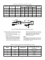
6-2. Refrigerant Piping Installation
6-2-1. Piping Materials and Joints Used
For the refrigerant piping installation, copper pipes
and joints are mainly used. Copper pipes and joints
suitable for the refrigerant must be chosen and
installed. Furthermore, it is necessary to use clean
copper pipes and joints whose interior surfaces are
less affected by contaminants.
(1) Copper Pipes
It is necessary to use seamless copper pipes
which are made of either copper or copper alloy
and it is desirable that the amount of residual oil
is less than 40 mg/10 m. Do not use copper
pipes having a collapsed, deformed or discolored portion (especially on the interior surface).
Otherwise, the expansion valve or capillary tube
may become blocked with contaminants.
As an air conditioner using R410A incurs
pressure higher than when using R22, it is
necessary to choose adequate materials.
Thicknesses of copper pipes used with R410A
are as shown in Table 6-2-1. Never use copper
pipes thinner than 0.8 mm even when it is
available on the market.
– 13 –
Table 6-2-1 Thicknesses of annealed copper pipes
Thickness (mm)
Nominal diameter
Outer diameter (mm)
R410A
R22
1/4
6.35
0.80
0.80
3/8
9.52
0.80
0.80
1/2
12.70
0.80
0.80
5/8
15.88
1.00
1.00
b) Socket Joints
Socket joints are such that they are brazed
for connections, and used mainly for thick
pipings whose diameter is larger than 20 mm.
Thicknesses of socket joints are as shown in
Table 6-2-2.
(2) Joints
For copper pipes, flare joints or socket joints are
used. Prior to use, be sure to remove all contaminants.
a) Flare Joints
Flare joints used to connect the copper pipes
cannot be used for pipings whose outer
diameter exceeds 20 mm. In such a case,
socket joints can be used.
Sizes of flare pipe ends, flare joint ends and
flare nuts are as shown in Tables 6-2-3 to 62-6 below.
Table 6-2-2 Minimum thicknesses of socket joints
Nominal diameter
Reference outer diameter of
copper pipe jointed (mm)
Minimum joint thickness
(mm)
1/4
6.35
0.50
3/8
9.52
0.60
1/2
12.70
0.70
5/8
15.88
0.80
6-2-2. Processing of Piping Materials
When performing the refrigerant piping installation,
care should be taken to ensure that water or dust
does not enter the pipe interior, that no other oil
other than lubricating oils used in the installed air
conditioner is used, and that refrigerant does not
leak. When using lubricating oils in the piping
processing, use such lubricating oils whose water
content has been removed. When stored, be sure to
seal the container with an airtight cap or any other
cover.
(1) Flare Processing Procedures and Precautions
a) Cutting the Pipe
By means of a pipe cutter, slowly cut the pipe
so that it is not deformed.
b) Removing Burrs and Chips
If the flared section has chips or burrs,
refrigerant leakage may occur. Carefully
remove all burrs and clean the cut surface
before installation.
– 14 –
c) Insertion of Flare Nut
d) Flare Processing
Make certain that a clamp bar and copper
pipe have been cleaned.
By means of the clamp bar, perform the flare
processing correctly.
Use either a flare tool for R410A or conventional flare tool.
Flare processing dimensions differ according
to the type of flare tool. When using a conventional flare tool, be sure to secure “dimension A” by using a gauge for size adjustment.
ØD
A
Fig. 6-2-1 Flare processing dimensions
Table 6-2-3 Dimensions related to flare processing for R410A
A (mm)
Nominal
diameter
Outer
diameter
(mm)
Thickness
(mm)
Conventional flare tool
Flare tool for
R410A clutch type
Clutch type
Wing nut type
1/4
6.35
0.8
0 to 0.5
1.0 to 1.5
1.5 to 2.0
3/8
9.52
0.8
0 to 0.5
1.0 to 1.5
1.5 to 2.0
1/2
12.70
0.8
0 to 0.5
1.0 to 1.5
2.0 to 2.5
5/8
15.88
1.0
0 to 0.5
1.0 to 1.5
2.0 to 2.5
Table 6-2-4 Dimensions related to flare processing for R22
A (mm)
Nominal
diameter
Outer
diameter
(mm)
Thickness
(mm)
Conventional flare tool
Flare tool for
R22 clutch type
Clutch type
Wing nut type
1/4
6.35
0.8
0 to 0.5
0.5 to 1.0
1.0 to 1.5
3/8
9.52
0.8
0 to 0.5
0.5 to 1.0
1.0 to 1.5
1/2
12.70
0.8
0 to 0.5
0.5 to 1.0
1.5 to 2.0
5/8
15.88
1.0
0 to 0.5
0.5 to 1.0
1.5 to 2.0
Table 6-2-5 Flare and flare nut dimensions for R410A
Nominal
diameter
Outer diameter
(mm)
Thickness
(mm)
1/4
6.35
3/8
Dimension (mm)
Flare nut
width (mm)
A
B
C
D
0.8
9.1
9.2
6.5
13
17
9.52
0.8
13.2
13.5
9.7
20
22
1/2
12.70
0.8
16.6
16.0
12.9
23
26
5/8
15.88
1.0
19.7
19.0
16.0
25
29
– 15 –
Table 6-2-6 Flare and flare nut dimensions for R22
Nominal
diameter
Outer diameter
(mm)
Thickness
(mm)
1/4
6.35
3/8
Dimension (mm)
Flare nut
width (mm)
A
B
C
D
0.8
9.0
9.2
6.5
13
17
9.52
0.8
13.0
13.5
9.7
20
22
1/2
12.70
0.8
16.2
16.0
12.9
20
24
5/8
15.88
1.0
19.4
19.0
16.0
23
27
3/4
19.05
1.0
23.3
24.0
19.2
34
36
6˚
to 4
45˚
B
A
C
43˚
D
to 4
5˚
Fig. 6-2-2 Relations between flare nut and flare seal surface
(2) Flare Connecting Procedures and Precautions
a) Make sure that the flare and union portions
do not have any scar or dust, etc.
b) Correctly align the processed flare surface
with the union axis.
c) Tighten the flare with designated torque by
means of a torque wrench. The tightening
torque for R410A is the same as that for
conventional R22. Incidentally, when the
torque is weak, the gas leakage may occur.
When it is strong, the flare nut may crack and
may be made non-removable. When choosing
the tightening torque, comply with values
designated by manufacturers. Table 6-2-7
shows reference values.
NOTE:
When applying oil to the flare surface, be sure to use
oil designated by the manufacturer. If any other oil is
used, the lubricating oils may deteriorate and cause
the compressor to burn out.
Table 6-2-7 Tightening torque of flare for R410A [Reference values]
Nominal
diameter
Outer diameter
(mm)
Tightening torque
N•m (kgf•cm)
Tightening torque of torque
wrenches available on the market
N•m (kgf•cm)
1/4
6.35
14 to 18 (140 to 180)
16 (160), 18 (180)
3/8
9.52
33 to 42 (330 to 420)
42 (420)
1/2
12.70
50 to 62 (500 to 620)
55 (550)
5/8
15.88
63 to 77 (630 to 770)
65 (650)
– 16 –
6-3. Tools
6-3-1. Required Tools
The service port diameter of packed valve of the outdoor unit in the air conditioner using R410A is changed to
prevent mixing of other refrigerant. To reinforce the pressure-resisting strength, flare processing dimensions and
opposite side dimension of flare nut (For Ø12.7 copper pipe) of the refrigerant piping are lengthened.
The used refrigerating oil is changed, and mixing of oil may cause a trouble such as generation of sludge,
clogging of capillary, etc. Accordingly, the tools to be used are classified into the following three types.
(1) Tools exclusive for R410A (Those which cannot be used for conventional refrigerant (R22))
(2) Tools exclusive for R410A, but can be also used for conventional refrigerant (R22)
(3) Tools commonly used for R410A and for conventional refrigerant (R22)
The table below shows the tools exclusive for R410A and their interchangeability.
Tools exclusive for R410A (The following tools for R410A are required.)
Tools whose specifications are changed for R410A and their interchangeability
R410A
air conditioner installation
No.
Used tool
Usage
Conventional air
conditioner installation
Existence of
new equipment
for R410A
Whether conventional equipment
can be used
Whether new equipment
can be used with
conventional refrigerant
Flare tool
Pipe flaring
Yes
*(Note 1)
OK
Copper pipe gauge for
adjusting projection
margin
Flaring by
conventional flare tool
Yes
*(Note 1)
*(Note 1)
Torque wrench
Connection of flare nut
Yes
NO GOOD
NO GOOD
Gauge manifold
Evacuating, refrigerant
charge, run check, etc.
Yes
NO GOOD
NO GOOD
Charge hose
Vacuum pump adapter
Vacuum evacuating
Yes
NO GOOD
OK
Electronic balance for
refrigerant charging
Refrigerant charge
Yes
NO GOOD
OK
Refrigerant cylinder
Refrigerant charge
Yes
NO GOOD
NO GOOD
Leakage detector
Gas leakage check
Yes
NO GOOD
OK
Charging cylinder
Refrigerant charge
(Note 2)
NO GOOD
NO GOOD
(Note 1) When flaring is carried out for R410A using the conventional flare tools, adjustment of projection
margin is necessary. For this adjustment, a copper pipe gauge, etc. are necessary.
(Note 2) Charging cylinder for R410A is being currently developed.
General tools (Conventional tools can be used.)
In addition to the above exclusive tools, the following equipments which serve also for R22 are necessary
as the general tools.
(1) Vacuum pump
(4) Reamer
(9) Hole core drill (Ø65)
Use vacuum pump by
(5) Pipe bender
(10) Hexagon wrench
attaching vacuum pump adapter.
(Opposite side 4mm)
(6) Level vial
(2) Torque wrench
(11) Tape measure
(7) Screwdriver (+, –)
(3) Pipe cutter
(12) Metal saw
(8) Spanner or Monkey wrench
Also prepare the following equipments for other installation method and run check.
(1) Clamp meter
(3) Insulation resistance tester
(2) Thermometer
(4) Electroscope
– 17 –
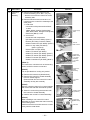
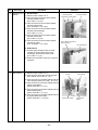
6-4. Recharging of Refrigerant
When it is necessary to recharge refrigerant, charge the specified amount of new refrigerant according to the
following steps.
Recover the refrigerant, and check no refrigerant
remains in the equipment.
When the compound gauge’s pointer has indicated
–0.1 Mpa (–76 cmHg), place the handle Low in the
fully closed position, and turn off the vacuum pump’s
power switch.
Connect the charge hose to packed valve service
port at the outdoor unit’s gas side.
Keep the status as it is for 1 to 2 minutes, and ensure
that the compound gauge’s pointer does not return.
Connect the charge hose of the vacuum pump
adapter.
Set the refrigerant cylinder to the electronic balance,
connect the connecting hose to the cylinder and the
connecting port of the electronic balance, and charge
liquid refrigerant.
Open fully both packed valves at liquid and gas
sides.
Place the handle of the gauge manifold Low in the
fully opened position, and turn on the vacuum pump’s
power switch. Then, evacuating the refrigerant in the
cycle.
(For refrigerant charging, see the figure below.)
Never charge refrigerant exceeding the specified amount.
If the specified amount of refrigerant cannot be charged, charge refrigerant bit by bit in COOL mode.
Do not carry out additional charging.
When additional charging is carried out if refrigerant leaks, the refrigerant composition changes in the
refrigeration cycle, that is characteristics of the air conditioner changes, refrigerant exceeding the
specified amount is charged, and working pressure in the refrigeration cycle becomes abnormally high
pressure, and may cause a rupture or personal injury.
(INDOOR unit)
(Liquid side)
(OUTDOOR unit)
Opened
(Gas side)
Refrigerant cylinder
(With siphon pipe)
Check valve
Closed
Open/Close valve
for charging
Service port
Electronic balance for refrigerant charging
Fig. 6-4-1 Configuration of refrigerant charging
– 18 –
Be sure to make setting so that liquid can be charged.
When using a cylinder equipped with a siphon, liquid can be charged without turning it upside down.
It is necessary for charging refrigerant under condition of liquid because R410A is mixed type of refrigerant.
Accordingly, when charging refrigerant from the refrigerant cylinder to the equipment, charge it turning the
cylinder upside down if cylinder is not equipped with siphon.
[ Cylinder with siphon ]
[ Cylinder without siphon ]
Gauge manifold
Gauge manifold
OUTDOOR unit
OUTDOOR unit
Refrigerant
cylinder
Refrigerant
cylinder
Electronic
balance
Electronic
balance
Siphon
R410A refrigerant is HFC mixed refrigerant.
Therefore, if it is charged with gas, the composition of the charged refrigerant changes and the
characteristics of the equipment varies.
Fig. 6-4-2
6-5. Brazing of Pipes
6-5-1. Materials for Brazing
(1) Silver brazing filler
Silver brazing filler is an alloy mainly composed of silver and copper. It is used to join iron, copper or copper
alloy, and is relatively expensive though it excels in solderability.
(2) Phosphor bronze brazing filler
Phosphor bronze brazing filler is generally used to join copper or copper alloy.
(3) Low temperature brazing filler
Low temperature brazing filler is generally called solder, and is an alloy of tin and lead. Since it is weak in
adhesive strength, do not use it for refrigerant pipes.
Phosphor bronze brazing filler tends to react with sulfur and produce a fragile compound water solution,
which may cause a gas leakage. Therefore, use any other type of brazing filler at a hot spring resort,
etc., and coat the surface with a paint.
When performing brazing again at time of servicing, use the same type of brazing filler.
6-5-2. Flux
(1) Reason why flux is necessary
• By removing the oxide film and any foreign matter on the metal surface, it assists the flow of brazing filler.
• In the brazing process, it prevents the metal surface from being oxidized.
• By reducing the brazing filler's surface tension, the brazing filler adheres better to the treated metal.
– 19 –
(2) Characteristics required for flux
• Activated temperature of flux coincides with
the brazing temperature.
• Due to a wide effective temperature range, flux
is hard to carbonize.
• It is easy to remove slag after brazing.
• The corrosive action to the treated metal and
brazing filler is minimum.
• It excels in coating performance and is harmless to the human body.
As the flux works in a complicated manner as
described above, it is necessary to select an
adequate type of flux according to the type and
shape of treated metal, type of brazing filler and
brazing method, etc.
6-5-3. Brazing
As brazing work requires sophisticated techniques,
experiences based upon a theoretical knowledge, it
must be performed by a person qualified.
In order to prevent the oxide film from occurring in
the pipe interior during brazing, it is effective to
proceed with brazing while letting dry Nitrogen gas
(N2) flow.
Never use gas other than Nitrogen gas.
(3) Types of flux
• Noncorrosive flux
Generally, it is a compound of borax and boric
acid.
It is effective in case where the brazing temperature is higher than 800°C.
• Activated flux
Most of fluxes generally used for silver brazing
are this type.
It features an increased oxide film removing
capability due to the addition of compounds
such as potassium fluoride, potassium chloride
and sodium fluoride to the borax-boric acid
compound.
(1) Brazing method to prevent oxidation
Attach a reducing valve and a flow-meter to
the Nitrogen gas cylinder.
Use a copper pipe to direct the piping material, and attach a flow-meter to the cylinder.
Apply a seal onto the clearance between the
piping material and inserted copper pipe for
Nitrogen in order to prevent backflow of the
Nitrogen gas.
When the Nitrogen gas is flowing, be sure to
keep the piping end open.
Adjust the flow rate of Nitrogen gas so that it
is lower than 0.05 m³/Hr or 0.02 MPa (0.2kgf/
cm²) by means of the reducing valve.
After
performing the steps above, keep the
Nitrogen gas flowing until the pipe cools
down to a certain extent (temperature at
which pipes are touchable with hands).
Remove the flux completely after brazing.
(4) Piping materials for brazing and used
brazing filler/flux
Piping
material
Used
brazing filler
Used
flux
M Flow meter
Copper - Copper Phosphor copper
Do not use
Copper - Iron
Silver
Paste flux
Iron - Iron
Silver
Vapor flux
Stop valve
Nitrogen gas
cylinder
From Nitrogen cylinder
Do not enter flux into the refrigeration cycle.
When chlorine contained in the flux remains
Pipe
Nitrogen
gas
within the pipe, the lubricating oil deteriorates.
Therefore, use a flux which does not contain
chlorine.
When adding water to the flux, use water
which does not contain chlorine (e.g. distilled
water or ion-exchange water).
Remove the flux after brazing.
Rubber plug
Fig. 6-5-1.
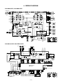
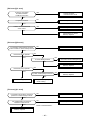
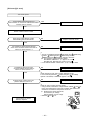
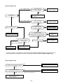
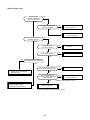
Circuit Configuration and Control Specifications
– 20 –
N-phase power supply lead
(White)
Reactor lead connector
(White)
– 21 –
CN701:
4-way valve connector
RY701:
4-way valve relay
Comp. lead
(Red) (White) (Black)
CN300:
Fan motor connector
CN602:
Outdoor temperature
(TO) sensor connector
12V
GND
CN806:
Optional connector
CN600:
Heat exchange temperature
(TE) sensor connector
5V
IC800: MCU
CN603:
Suction temperature
(TS) sensor connector
CN601:
Discharge temperature
(TD) sensor connector
CN500:
Fan drive circuit
Case thermo
Q300 to Q305:
connector
FET (QTY: 6P)
CN700:
CN605:
PMV connector
Sub SW board connector
J800 to 803, 806
Model switch jumper line
Comp. drive circuit
Q200 to Q205: IGBT (QTY: 6P)
IC200: Drive IG (QTY: 1P)
7. CONTROL SPECIFICATIONS
Serial lead (Orange)
7-1. Outdoor Controls
DB01:
Single-phase rectifier diode
L-phase power supply lead
(Black)
7-1-1. Print Circuit Board
F03: 3.15A fuse
<Viewed from parts of P.C board>
C12, 13, 14
electrolytic capacitor
DB02:
High power factor diode
Q404:
High power factor circuit IGBT
RAV-SM561AT-E, RAV-SM801AT-E
P.C. board earth lead
(Black)
<MCC-5009>
F01, 02, 25A fuse
Communication signal
(To MCC-1531)
CN06
IGBT
(Compressor drive device)
AC output
(To MCC-1531)
CN13
TH sensor
CN600
Earth ground
CN03
DC320V output
(To MCC-1531)
CN04
– 22 –
Compressor output
CN09, CN10, CN11
Mains (Neutral) input
CN02
Mains (Live) input
CN01
Rectifier
Rectifier connectors
P29 (Red), P28 (Black),
P21 (Orange), P24 (Brown)
Reactor Connector
Capacitor
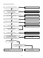
RAV-SM1101AT-E, RAV-SM1401AT-E
DC15V output
(To MCC-1531)
CN05
<IPDU : MCC-1438>
Reactor connector
EEPROM-IC
IC801
Model selection jumpers
(Available only service P.C. board)
J800 to J803
Dip switch
SW801
P.M.V. CN702
Case thermo. switch
CN500
Communication signal
(To MCC-1438)
CN800
TD sensor
CN600
Serial signal
(To terminal block)
CN02
TO sensor
CN601
TE sensor
CN604
AC input
(To MCC-1438)
CN01
TS sensor
CN605
– 23 –
Optional connector
CN804
4-way valve
CN700
Fan motor revolution
CN300
Fan motor output
CN301
DC15V input
(To MCC-1438)
CN04
DC320V input
(To MCC-1438)
CN03
<CDB : MCC-1531>
Refrigerant recovery Switch
SW802
7-2. Outline of Main Controls
1. Pulse Modulating Valve (PMV) control
1) For PMV with 50 to 500 pulses during operation, respectively.
2) In cooling operation, PMV is controlled with the temperature difference between TS sensor and TC
sensor.
3) In heating operation, PMV is controlled with the temperature difference between TS sensor and TE
sensor.
4) For the temperature difference in items 2) and 3), 1 to 5K is aimed as the target in both cooling and
heating operations.
5) When the cycle excessively rose in both cooling and heating operations, PMV is controlled by TD sensor.
The aimed value is usually 103°C for SM561, SM801 and 92°C for SM1101, SM1401 in both cooling and
heating operations.
REQUIREMENT
A sensor trouble may cause a liquid back-flow or abnormal overheat resulting in excessive shortening of the
compressor life. In a case of trouble on the compressor, be sure to check there is no error in the resistance
value an the refrigerating cycle of each sensor after repair and then start the operation.
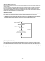
2. Discharge temperature release control
1) This function controls the operation frequency, that
is, lowers the operation frequency when the
discharge temperature has not lower or the
discharge temperature has rapidly risen during
PMV control. It subdivides the frequency control up
to a unit of 0.6 Hz to stabilize the cycle.
2) When the discharge temperature is detected in an
abnormal stop zone, the unit stops the compressor
and restarts after 2 minutes 30 seconds. The error
counter is cleared when it has continued the
operation for 10 minutes.
If the abnormal stop zone has been detected by 4
times without clearing of counter, an error “P03” is
displayed.
* The cause is considered as excessively little
amount of refrigerant, defective PMV, or clogging
of cycle.
[°C]
a
b
c
d
e
SM561, SM801
117
107
103
100
93
SM1101, SM1401
111
106
100
95
90
TD [˚C]
Error stop ("P03" display with 4 times of error counts)
a
Frequency down
b
c
Frequency holding
d
Frequency slow-up
(Up to command)
e
As command is
Current [A]
Frequency down
I1
3. Current release control
The output frequency and the output voltage are
controlled by AC current value detected by T02 on the
outdoor P.C. board so that input current of the inverter
does not exceed the specified value.
SM561
SM801
Hold
Hold
Normal operation
I1–0.5
SM1101
SM1401
COOL HEAT
COOL HEAT
Objective model
11 value [A]
COOL
HEAT
COOL
HEAT
10.1
12.0
12.2
14.0
18.9
19.7
– 24 –
19.7
19.7
4. Outdoor fan control
Allocations of fan tap revolutions [rpm]
W1
W2
W3
W4
W5
W6
W7
W8
W9
WA
WB
WC
WD
WE
WF
SM561
200
300
350
410
480
500
530
560
640
670
700
750
800
840
840
SM801
200
300
350
410
480
500
530
560
640
670
700
750
840
940
980
SM1101
250
280
320
360
410
460
520
580
640
700
760
860
860
900
930
SM1401
250
280
320
360
410
460
520
580
640
700
760
860
860
900
970
1) Cooling fan control
The outdoor fan is controlled by TE, TD, and TO sensors and also revolution frequency of the operation. The outdoor is controlled by every 1 tap of DC fan control (15 taps).
Only during 60 seconds after the operation has started, the fan is fixed with the maximum fan tap
which corresponds to the zone in the following table.
After then the fan is controlled by TE sensor temperature.
Considering a case that TE sensor has come out of the holder, the fan is controlled so that revolution
frequency of the fan increases regardless of TE if temperature of TD sensor has risen.
a
b
SM561, SM801
36
32
SM1101, SM1101
29
26
Operation with WE
TE [˚C]
TD [˚C]
+1 tap/20 seconds
85
a
80
rpm hold
Operation with
maximum tap in
each zone
75
b
–1 tap/20 seconds
65
Usual fan control
(The operation frequency differs according to the model type.)
Below 30Hz
Above 30 Hz below 45 Hz
Above 45 Hz
Temp. range
Min
Max
Min
Max
Min
Max
29°C < TO
W5
WA
W7
WC
W9
WF
15 < TO < 29°C
W3
W7
W5
W9
W7
WB
5 < TO < 15°C
W2
W5
W4
W7
W6
W9
0 < TO < 5°C
W1
W3
W3
W5
W4
W7
TO < 0°C
W1
W2
W2
W4
W3
W5
TO error
W1
WF
W1
WF
W1
WF
– 25 –
2) Heating fan control
The outdoor fan is controlled by TE sensor, TO sensor and the operation frequency.
(From Min. W1 to Max. are controlled according to the following table.)
During 3 minutes after start-up, the fan is fixed
with the maximum fan tap corresponding to
TE [˚C]
zone in the following table. After then the fan is
–2 tap/20 seconds
controlled by temperature of TE sensor.
STOP timer count
24
If status, TE ≥ 24°C continues for 5 minutes, the
–2 tap/20 seconds
operation stops. This status is same to the usual
21
Thermo-OFF which has no alarm display, and the
–1 tap/20 seconds
fan restarts after 2 minutes and 30 seconds. This
18
intermittent operation is not abnormal.
rpm hold
When the above status occurs frequently, it
15
is considered that the filter of suction part of the
+1 tap/20 seconds
indoor unit is stain. Clean the filter and then
restart the operation.
(The operation frequency differs according to the model type. The case of SM1101 is shown in the table below.)
Temp. range
Below 33 Hz
Above 33 Hz below 51 Hz
Above 51 Hz
10°C < TO
W7
W8
W9
5 < TO < 10°C
WA
WB
WF
TO < 5°C
WF
WF
WF
TO error
WF
WF
WF
Maximum
5. Coil heating control
1) This control function heats the compressor by turning on the stopped compressor instead of a case
heater. It purposes to prevent slackness of the refrigerant inside of the compressor.
2) As usual, turn on power of the compressor for the specified time before a test run after installation,
otherwise a trouble of the compressor may be caused. As same as a test run, it is recommended to turn
on power of the compressor beforehand when starting operation after power of the compressor has been
interrupted for a long time.
3) A judgment for electricity is performed by TD and TO sensors. If TO sensor is defective, a backup control
is automatically performed by TE sensor. For a case of defective TO sensor, judge it with the outdoor LED
display.
4) Coil heating is controlled by TD and TE sensor.
5) For every model, the power is turned off when TD is 30°C or more.
(In trouble of TE sensor)
TO [˚C]
Power-ON condition
TD < 30˚C
18
15
10
8
TE [˚C]
No power-ON
Continuous ON (L)
20
18
12
10
No power-ON
Continuous ON (L)
Continuous ON (M)
* TD sensor is read in once per 15 minutes
.
Continuous ON (M)
* TO sensor is read in once per 15 minutes
SM1101, SM1401
(Object: SM561, SM801)
TE [˚C]
0
–1
–6
–7
No power-ON
L
20W and equivalent
M
40W and equivalent
SM561, SM801
Continuous ON (L)
Continuous ON (H)
– 26 –
L
10W and equivalent
H
30W and equivalent
NOTIFICATION
It is not an abnormal phenomenon that electro-noise may be heard while heating the coil.
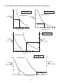
6. Short intermittent operation preventive control
The compressor may not stop for preventing the compressor for 3 to 10 minutes after start of the
operation even if Thermo-OFF signal has been received from the indoor. This phenomenon is not
abnormal. (Continuous operation time of the compressor differs according to the operating status.)
If the equipment is stopped from the remote controller, the operation does not continue.
7. High-pressure suppression TE control (Only for SM1101, SM1401)
This control suppresses that voltage becomes abnormally higher during cooling operation.
Stop the compressor under condition of TE ≥ 67°C, and count 1 on the error count.
After 2 minutes 30 seconds passed, if TE < 67°C, the compressor restarts and the error count is
cleared when the operation continues for 10 minutes.
When TE ≥ 67°C is detected again within 10 minutes, 1 is added to the error count and restart is
repeated.
If the error counts 10 are recognized, it is determined as an error and restart is not performed. Error
code ‘P04’ is displayed.
After restarting the compressor, continue controlling by using 70% to 90% of the control value of the
current release control for minimum 30 minutes.
8. Over-current preventive control
This control function stops the compressor when over-current preventive circuit has detected an
abnormal current.
The compressor restarts with error count 1 after 2 minutes 30 seconds.
If the error counts 8 are recognized, it is determined as an error and restart is not performed. Error
code ‘H01’, ‘H02’ or ‘P26’ is displayed.
9. Current release value shift control (Cooling and Dry operation)
1) Object: SM1101, SM1401
This control function prevents troubles of the electron parts such as G-Tr of inverter of compressor
drive system and troubles of the compressor during cooling operation.
This control function corrects the current release control value (11) in item 7-2. by TO sensor value.
The value to be corrected is based upon the following control diagram and correction value table.
TO [˚C]
Corrected value
T+8
T+7
T+5
T+4
T+2
T+1
T
T-1
I1 x a%
I1 x b%
SM1101, SM1401
T
a
b
c
d
39°C
70%
80%
85%
90%
I1 x c%
I1 x d%
As I1
Current release value shift control
2) Object: SM561, SM801
The current release value of the models
above are selected from the right table
according to TO sensor value.
TO
– 27 –
SM561
SM801
45 ≤ TO
4.7
5.1
40 ≤ TO < 45
6.2
7.1
TO < 40
10.1
12.2
10. Defrost control
In heating operation, defrost operation is performed when TE sensor temperature satisfies any condition in A zone to D zone.
The defrost operation is immediately finished if TE sensor temperature has become 12°C or more, or it
also is finished when condition of 7°C ≤ TE < 12°C has continued for 1 minute. The defrost operation is
also finished when defrost operation has continued for 10 minutes even if TE sensor temperature has
become 7°C or lower.
After defrost operation has finished, the compressor and the outdoor fan start heating operation after
stopped for approx. 50 seconds.
Start of heating operation
0
10
15
c
b
a
d
[min.]
TE [ºC]
–4 (–5)
A zone
–6 (–10)
–10 (–13)
B zone
–25 (–18)
D zone
C zone
*
Numerals enclosed with parentheses represent numeral values of SM1101 and SM1401.
* The minimum TE value between 10 and 15 minutes after heating operation has started is stored in memory as TE0.
A zone
Defrost operation is performed in this zone when TE0-TE ≥ 3 continued for T seconds.
B zone
Defrost operation is performed in this zone when TE0-TE ≥ 3 continued for T seconds.
C zone
Defrost operation is performed when this zone continued for T seconds.
D zone
Defrost operation is performed when this zone continued for T seconds.
SM561, SM801
SM1101, SM1401
a
35
50
b
29
35
c
29
30
d
90
90
T
20
20
– 28 –
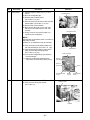
8. TROUBLESHOOTING
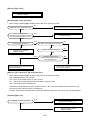
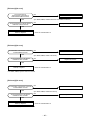
8-1. Summary of Troubleshooting
<Wired remote controller type>
1. Before troubleshooting
1) Required tools/instruments
• + and – screwdrivers, spanners, radio cutting pliers, nippers, push pins for reset switch
• Tester, thermometer, pressure gauge, etc.
2) Confirmation points before check
The following operations are normal.
a) Compressor does not operate.
• Is not 3-minutes delay (3 minutes after compressor OFF)?
• Does not thermostat turn off?
• Does not timer operate during fan operation?
• Is not outside high-temperature operation controlled in heating operation?
• Is not Thermo-OFF setup by “Application Control Kit” (TCB-PCOS1E) sold separately?
b) Indoor fan does not rotate.
• Does not cool air discharge preventive control work in heating operation?
c) Outdoor fan does not rotate or air volume changes.
• Does not high-temperature release operation control work in heating operation?
• Does not outside low-temperature operation control work in cooling operation?
• Is not defrost operation performed?
d) ON/OFF operation cannot be performed from remote controller.
• Is not the control operation performed from outside/remote side?
• Is not automatic address being set up?
(When the power is turned on at the first time or when indoor unit address setting is changed, the
operation cannot be performed for maximum approx. 5 minutes after power-ON.)
Did you return the cabling to the initial positions?
Are connecting cables of indoor unit and remote controller correct?
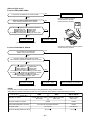
3) Troubleshooting procedure
When a trouble occurred, check the parts along with the following procedure.
Trouble → Confirmation of check code display → Check defective position and parts.
NOTE :
For cause of a trouble, power conditions or malfunction/erroneous diagnosis of microcomputer due to
outer noise is considered except the items to be checked. If there is any noise source, change the cables
of the remote controller to shield cables.
– 29 –
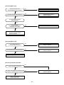
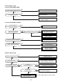
<Wireless remote controller type> (Only for 4-way air discharge cassette type models)
1. Before troubleshooting
1) Required tools/instruments
• + and – screwdrivers, spanners, radio cutting pliers, nippers, etc.
• Tester, thermometer, pressure gauge, etc.
2) Confirmation points before check
The following operations are normal.
a) Compressor does not operate.
• Is not 3-minutes delay (3 minutes after compressor OFF)?
• Does not thermostat turn off?
• Does not timer operate during fan operation?
• Is not outside high-temperature operation controlled in heating operation?
• Is not Thermo-OFF setup by “Application Control Kit” (TCB-PCOS1E) sold separately?
b) Indoor fan does not rotate.
• Does not cool air discharge preventive control work in heating operation?
3) Outdoor fan does not rotate or air volume changes.
• Does not high-temperature release operation control work in heating operation?
• Does not outside low-temperature operation control work in cooling operation?
• Is not defrost operation performed?
4) ON/OFF operation cannot be performed from remote controller.
• Is not forced operation performed?
• Is not the control operation performed from outside/remote side?
• Is not automatic address being set up?
Did you return the cabling to the initial positions?
Are connecting cables between indoor unit and receiving unit correct?
2. Troubleshooting procedure
(When the power is turned on at the first time or when indoor unit address setting is changed, the operation
cannot be performed for maximum approx. 5 minutes after power-ON.)
When a trouble occurred, check the parts along with the following procedure.
Trouble →
Confirmation of lamp display
(When 4-way air discharge cassette type wireless remote controller is connected)
→
Check defective
position and parts.
1) Outline of judgment
The primary judgment to check where a trouble occurred in indoor unit or outdoor unit is performed with
the following method.
Method to judge the erroneous position by flashing indication on the display part of indoor unit
(sensors of the receiving unit)
The indoor unit monitors operating status of the air conditioner, and the blocked contents of self-diagnosis
are displayed restricted to the following cases if a protective circuit works.
– 30 –
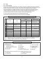
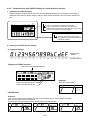
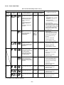
8-2. Check Code List
Error mode detected by indoor unit
¥ : Flash, ¡ : Go on, l : Go off
Wireless sensor
lamp display
Diagnostic function
Wired remote
controller
Cause of operation
Status of air
conditioner
Judgment and measures
Condition
Operation
Timer
Ready
Check code
¥
l
l
E03
No communication from remote controller (including wireless) and
communication adapters
Stop
Displayed when
(Automatic reset) error is detected
1. Check cables of remote controller and communication adapters.
• Handy remote controller LCD display OFF (Disconnection)
• Central remote controller [97] check code
Stop
Displayed when
(Automatic reset) error is detected
1. Outdoor unit does not completely operate.
• Inter-unit wire check, correction of miswiring, case thermo operation
• Outdoor P.C. board check, P.C. board wires check
2. In normal operation
P.C. board (Indoor receiving/Outdoor sending) check
l
l
¥
E04
The serial signal is not output from outdoor unit to indoor unit.
• Miswiring of inter-unit wires
• Defective serial sensing circuit on outdoor P.C. board
• Defective serial receiving circuit on indoor P.C. board
¥
¥
¥
¥
l
¥
l
l
l
l
l
¥
– 31 –
E08
Duplicated indoor unit addresses
¥
¥
¥
L03
Duplicated indoor master units
L07
L08
There is group line in individual indoor units.
Unsetting of indoor group address
¥
L09
¡
¥
l
¥
l
1. Check whether there is modification of remote controller connection (Group/Individual)
or not after power has been turned on (finish of group configuration/address check).
• If group configuration and address are not normal when the power has been turned
on, the mode automatically shifts to address setup mode. (Resetting of address)
Stop
Displayed when
error is detected
Unset indoor capacity
Stop
Displayed when
1. Set the indoor capacity. (DN=I1)
error is detected
L30
Abnormal outside interlock input
Stop
Displayed when 1. Check outside devices.
error is detected 2. Check indoor P.C. board.
¥
P01
Fan motor thermal protection
Stop
Displayed when 1. Check thermal relay of fan motor.
error is detected 2. Check indoor P.C. board.
¥
¥
P10
Float switch operation
• Disconnection, coming-off, defective float switch contactor of float circuit
Stop
1. Defect of drain pump
Displayed when 2. Clogging of drain pump
error is detected 3. Check float switch.
4. Check indoor P.C. board.
l
¥
¥
P12
Indoor DC fan error
Stop
1. Defective detection of position
Displayed when 2. Over-current protective circuit of indoor fan driving unit operates.
error is detected 3. Lock of indoor fan
4. Check indoor P.C. board.
¥
l
¥
P19
Error in 4-way valve system
• Indoor heat exchanger temperature lowered after start of heating
operation.
1. Check 4-way valve.
Stop
Displayed when
(Automatic reset) error is detected 2. Check indoor heat exchanger (TC/TCJ) sensor.
3. Check indoor P.C. board.
¥
l
¥
P31
Own unit stops while warning is output to other indoor units.
Stop (Sub unit) Displayed when 1. Judge sub unit while master unit is in [E03], [L03], [L07], [L08].
(Automatic reset) error is detected 2. Check indoor P.C. board.
¥
¥
l
F01
Stop
Displayed when 1. Check indoor heat exchanger temperature sensor (TCJ).
Coming-off, disconnection or short of indoor heat exchanger sensor (TCJ) (Automatic
reset) error is detected 2. Check indoor P.C. board.
¥
¥
l
F02
Coming-off, disconnection or short of indoor heat exchanger sensor (TC)
Stop
Displayed when 1. Check indoor heat exchanger temperature sensor (TC).
(Automatic reset) error is detected 2. Check indoor P.C. board.
¥
¥
l
F10
Coming-off, disconnection or short of indoor heat exchanger sensor (TA)
Stop
Displayed when 1. Check indoor heat exchanger temperature sensor (TA).
(Automatic reset) error is detected 2. Check indoor P.C. board.
¥
¥
l
F29
Indoor EEPROM error
• EEPROM access error
Stop
Displayed when 1. Check indoor EEPROM. (including socket insertion)
(Automatic reset) error is detected 2. Check indoor P.C. board.
¥
l
l
E10
Communication error between indoor MCU
• Communication error between fan driving MCU and main MCU
1. Check wires of remote controller.
Stop
Displayed when
(Automatic reset) error is detected 2. Check power wires of indoor unit.
3. Check indoor P.C. board.
¥
l
l
E18
Regular communication error between master and sub indoor units or
between main and sub indoor units
1. Check wires of remote controller.
Stop
Displayed when
(Automatic reset) error is detected 2. Check indoor power wire.
3. Check indoor P.C. board.
Error mode detected by outdoor unit
¥ : Flash, ¡ : Go on, l : Go off
Wireless sensor
lamp display
Diagnostic function
Wired remote
controller
Cause of operation
Status of air
conditioner
Condition
Judgment and measures
Operation
Timer
Ready
Check code
l
¥
l
H01
Breakdown of compressor
• Displayed when error is detected
Stop
1. Check power voltage. AC200V ± 20V
Displayed when
error is detected 2. Overload operation of refrigerating cycle
3. Check current detection circuit at AC side.
l
¥
l
H02
Compressor does not rotate.
• Over-current protective circuit operates after specified time passed when
compressor had been activated.
Stop
1. Trouble of compressor (Compressor lock, etc.) : Replace compressor.
Displayed when
error is detected 2. Defective wiring of compressor (Phase missing)
3. Phase-missing operation of power supply (3-phase model)
l
¥
l
H03
Current detection circuit error
• Current value at AC side is high even during compressor-OFF.
• Phase of power supply is missed.
Stop
1. Compressor immediately stops even if restarted. : Check IPDU.
Displayed when
error is detected 2. Phase-missing operation of power supply
Check 3-phase power voltage and wires.
Stop
Displayed when 1. Check wires of CDB and IPDU.
error is detected 2. Abnormal overload operation of refrigerating cycle
– 32 –
¥
¡
¥
L29
Outdoor unit and other errors
• Communication error between CDB and IPDU
(Coming-off of connector)
• Heat sink temperature error
(Detection of temperature over specified value)
¥
¡
¥
L31
Phase detection protective circuit operates. (Normal models)
¥
l
¥
P03
Discharge temperature error
• Discharge temperature over specified value was detected.
Stop
1. Check refrigerating cycle. (Gas leak)
Displayed when
error is detected 2. Trouble of PMV
3. Check Td sensor.
¥
l
¥
P04
High-pressure protection error by TE sensor
(Temperature over specified value was detected.)
Stop
1. Overload operation of refrigerating cycle
Displayed when
error is detected 2. Check outdoor temperature sensor (TE).
3. Check outdoor CDB P.C. board.
¥
l
¥
P22
Outdoor DC fan error
Stop
1. Defective detection of position
Displayed when 2. Over-current protective circuit of outdoor fan driving unit operates.
error is detected 3. Lock of outdoor fan
4. Check outdoor CDB P.C. board.
¥
l
¥
P26
Inverter over-current protective circuit operates. (For a short time)
Short voltage of main circuit operates.
Stop
¥
l
¥
P29
IPDU position detection circuit error
Stop
¥
¥
¡
F04
Coming-off, disconnection or short of outdoor temperature sensor (TD)
Stop
Displayed when 1. Check outdoor temperature sensor (TD).
error is detected 2. Check outdoor CDB P.C. board.
¥
¥
¡
F06
Coming-off, disconnection or short of outdoor temperature sensor (TE/TS)
Stop
Displayed when 1. Check outdoor temperature sensor (TE/TS).
error is detected 2. Check outdoor CDB P.C. board.
¥
¥
¡
F08
Coming-off, disconnection or short of outdoor temperature sensor (TO)
Operation continues. Displayed when 1. Check power phase order (Reversed phase)/phase missing.
(Compressor stops.) error is detected 2. Check outdoor P.C. board.
Displayed when 1. Inverter immediately stops even if restarted. : Compressor motor rare short
error is detected 2. Check IPDU. : Cabling error
Displayed when 1. Position detection circuit operates even if operating compressor by removing 3P
error is detected
connector. : Replace IPDU.
Displayed when 1. Check outdoor temperature sensor (TO).
Operation continues. error
is detected 2. Check outdoor CDB P.C. board.
For an error mode detected in outdoor unit, the fan operates because sub unit of a group operation does not communicate with the outdoor unit.
Error mode detected by remote controller or network adapter
¥ : Flash, ¡ : Go on, l : Go off
Wireless sensor
lamp display
Operation
Timer
Ready
Wired remote
controller
Check code
No check code
is displayed.
(Remote
controller does
not operate.)
—
—
—
¥
l
l
E01*2
¥
l
l
¥
l
l
– 33 –
¥
¡
¥
Diagnostic function
Status of air
conditioner
Cause of operation
No communication with master indoor unit
• Remote controller wire is not correctly connected.
• Power of indoor unit is not turned on.
• Automatic address cannot be completed.
Stop
Condition
Judgment and measures
Remote controller power error, Defective indoor EEPROM
1. Check remote controller inter-unit wires.
2. Check remote controller.
—
3. Check indoor power wires.
4. Check indoor P.C. board.
5. Check indoor EEPROM. (including socket insertion)
: Phenomenon of automatic address repetition occurred.
Signal receiving of remote controller is defective.
1. Check remote controller inter-unit wires.
Displayed when
error is detected 2. Check remote controller.
3. Check indoor power wires.
4. Check indoor P.C. board.
No communication with indoor master unit
• Disconnection of inter-unit wire between remote controller and
master indoor unit (Detected at remote controller side)
Stop
(Automatic restart)
• When there is center,
operation continues.
E02
Signal sending error to indoor unit
(Detected at remote controller side)
Stop
Signal sending of remote controller is defective.
(Automatic restart)
Displayed when
• When there is center, error is detected 1. Check sending circuit inside of remote controller.
: Replace remote controller.
operation continues.
E09
Multiple master remote controllers are recognized.
(Detected at remote controller side)
Stop
(Sub unit continues
operation.)
Displayed when 1. Check there are multiple master units for 2 remote controllers
(including wireless).
error is detected
: Master unit is one and others are sub units.
Stop
(Automatic restart)
Displayed when
error is detected
L20
Duplicated indoor central addresses on communication of central
Central
control system (AI-NET)
remote controller (Detected by central controller side)
98
—
*3
Multiple network adapters on remote controller communication line
Central
(Detected by central controller side)
remote controller
99
—
—
—
—
—
—
Central
remote controller
97
—
—
—
Central
Indoor Gr sub unit error (Detected by central controller side)
remote controller
b7
—
*3
Interruption of central control system (AI-NET) communication circuit
(Detected by central controller side)
1. Check address setup of central control system network.
(Network adapter SW01)
2. Check network adapter P.C. board.
Operation continues.
1. Check multiple network adapters.
Displayed when
error is detected 2. Check inter-unit wire/miswiring of remote controller.
: Only one network adapter on remote controller communication line
Operation continues.
(According to handy
remote controller)
1. Check communication line/miswiring. Check power of indoor unit.
Displayed when 2. Check communication. (XY terminals)
error is detected 3. Check network adapter P.C. board.
4. Check central controller (such as central control remote controller, etc.).
—
Continuation/stop
(Based on a case)
Displayed when
error is detected Check the check code of corresponding unit by handy remote controller.
*2 Check code is not displayed by wired remote controller. (Usual operation of air conditioner is disabled.)
For wireless type models, E01 is notified by the display lamp.
*3 These errors are related to communication of remote controllers (A, B) and central system (AI-NET, X, Y), and [E01], [E02], [E03], [E09], or [E18] is displayed or no check code is displayed on the remote controller
according to the error contents.
8-3. Error Mode Judgment by LED Display of Outdoor Unit
There provided Dip switch (SW801) and LED on the “Application Control Kit” (TCB-PCOS1E) sold separately for
SM56 and SM80 models, and on the outdoor unit P.C. board for SM110 and SM140 models respectively.
The status of the outdoor unit at that time can be known by switching this Dip switch. The lighting status of LED
also notifies the judged stage before the outdoor error has been determined and displayed on the remote
controller. An error of the outdoor temp. sensor (TO) may be confirmed only by LED display according to the
indoor unit to be combined.
Model
Dip SW
SM56, 80*
SW01
SM110, 140
(MCC-1531)
SW802
Bit 1
LED
D01 (Red)
D02 (Yellow)
D03 (Yellow)
D04 (Yellow)
D800 (Red)
D801 (Yellow)
D802 (Yellow)
D803 (Yellow)
Bit 2
For error display, refer to
(Table A) on the next page.
OFF
During timer short
OFF
²
l
l
l
During pump down operation
l
ON
²
²
Protective operation count
In normal time, Count 1
Count 2, Count 3
Count 4, Count 5
Count 6, Count 7
Protective operation
OFF
l l
l ¡
¡ l
¡ ¡
²²
²
During backup
control
¥
PMV opening data (Lower 4 bit data)
OFF
ON
Add 16 pulses
if this LED goes on.
Add 8 pulses
if this LED goes on.
Add 4 pulses
if this LED goes on.
Add 2 pulses
if this LED goes on.
PMV opening data (Upper 4 bit data)
ON
ON
Add 256 pulses
if this LED goes on.
Add 128 pulses
if this LED goes on.
Add 64 pulses
if this LED goes on.
Add 32 pulses
if this LED goes on.
The total pulse counts equivalent to lighting LED at each position represents PMV
opening degree. For example, the case of ¡ll¡ ll¡¡ (Upper 4 bit, Lower
4 bit) represents 256 + 32 + 4 + 2 = 294 pulses.
¡ : Go on
l : Go off
² : 1Hz-flash
¥ : 5Hz-flash
* For Models ROA-AP40 to AP80, the error mode judgment by the above LED display is available under condition which “Application Control Kit” (TCB-PCOS1E) sold separately is connected.
(Note)
Never touch part other than Dip switch of “Application Control Kit” (TCB-PCOS1E).
AC230V is applied to all the electronic products, so an electric shock may be caused.
– 34 –
8-4. Contents of Error Display
• When multiple errors are detected, the latest error is displayed.
• When LED display is ¡ (Go on), there is the main cause of trouble on the objective part of control at CDB
side and the unit stops.
• When LED display is ¥ (Flash), there is the main cause of trouble on the objective part of control at IPDU
side and the unit stops.
• When case thermostat operates, the communication is interrupted on the serial circuit. If continuing the case
thermostat operation, a serial communication error occurs because serial sending to the indoor unit is interrupted.
Check code
Item
No.
LED display
Type A
Type B
D800
(Red)
D801
(Yellow)
D802
(Yellow)
D803
(Yellow)
l
l
1
TE sensor error
F06
18
¡
l
2
TD sensor error
F04
19
¡
¡
3
TS sensor error
F06
18
l
4
TO sensor error
F08
1B
¡
l
5
Discharge temp. error
P03
1E
l
l
l
¡
¡
6
DC outdoor fan error
P22
1A
¡
¡
¡
l
l
l
l
l
l
7
Communication error between IPDU
(with system suspended)
L29
1C
¡
l
l
¡
8
High-pressure release operation
P04
21
¡
Case thermo operation
E04
04
10
EEPROM error
—
—
¡
¡
l
l
l
¡
9
l
l
11
Communication error between IPDU
(without system suspended)
—
—
l
l
¡
¡
12
G-Tr short-circuit protection
P26
14
¥
Detection circuit error
P29
16
l
l
13
¥
14
Current sensor error
H03
17
¥
¥
15
Comp. lock error
H02
1D
l
¥
16
Comp. breakdown
H01
1F
¥
l
l
l
l
l
17
TH sensor error
L29
1C
¥
¥
¥
l
l
l
l
l
l
¡ : Go on
l : Go off
¡
¡
¥
¡
¡
¥ : Flash (5Hz)
<<Check code>>
The check codes are classified into Type A and Type B according to the used remote controller. Be sure to
check the remote controller which you use.
Type A :
Neutral 2-cores type wired remote controller such as RBC-AMT21E, RBC-AS21E, and wireless remote controller kit such as TCB-AX21U (W)-E
Type B :
Polarized 3-cores type wired remote controller such as RBC-SR1-PE, RBC-SR2-PE, and central control remote
controller such as RBC-CR64-PE
– 35 –
8-5. Troubleshooting Procedure for Each Check Code
8-5-1. New Check Code/Present Check Code (Central Control Side)
[E01 error]/*[99 error]
* : When central controller [99] is displayed, there are other causes of error.
NO
Correct inter-unit cable of remote controller.
Is inter-unit cable of A and B normal?
YES
Is there no disconnection
or contact error of connector on harness
from terminal block of indoor unit?
YES
Correct connection of connector.
Check circuit cables.
NO
NO
Is group control operation?
YES
NO
Check power connection of indoor unit.
(Turn on power again.)
NO
Check indoor P.C. board.
Defect
Replace
YES
Correct as a master unit/a sub unit
(Remote controller address connector)
Is power of all indoor units turned on?
YES
Is power supplied to remote controller?
AB terminal: Approx. DC18V
®
YES
Are two remote controllers
set without header unit?
NO
®
Check remote controller P.C. board.
Defect
Replace
[E09 error]/*[99 error]
* : When central controller [99] is displayed, there are other causes of error.
Are two remote controllers
set without header unit?
YES
Correct as a header unit/a follower unit
(Remote controller address connector)
NO
®
Check remote controller P.C. board.
Defect
Replace
– 36 –
[E04 error]/[04 error]
NO
Does outdoor unit operate?
YES
NO
Is setup of group address correct?
Check item code [14].
YES
NO
Correct inter-unit wire.
Are 1, 2, 3 inter-unit wires normal?
YES
Are connections from connectors
of inter-terminal blocks (1, 2, 3)
of indoor/outdoor units normal?
NO
Correct connection of connector.
YES
Does voltage between
2 and 3 of inter-terminal blocks (1, 2, 3)
of indoor unit vary?*
YES
®
Check indoor P.C. board.
Defect
Replace
NO
shown in the following figure,
* As
perform measurement within
20 seconds after power ON.
Black
3
S5277G
White
2
1
Inter-terminal block
For SM56, SM80
main circuit on control
P.C. board
Is DC280V applied between
terminals of electrolytic capacitor
of IPDU main circuit?
For SM56, SM80,
check case thermo.
NO
Replace IPDU.
YES
Is DC7V power supplied to CDB?
Are cablings between Pin 2 and Pin 5
of CN800 and between IPDU
and CDB normal?
NO
Replace IPDU.
Correct connection of connector.
YES
NO
Is case thermo (CN500) connected?
YES
®
®
Check indoor P.C. board .
Defect
Replace
Check CDB.
Defect
Replace
NO
Does case thermo operate?
YES
Check/Correct charged
refrigerant amount.
– 37 –
Correct connection of connector.
[E10 error]/[CF error]
®
Check indoor control P.C. board.
Defect
Replace
[E18 error]/[97 error] *[99 error]
* : When central controller [99] is displayed, there are other causes of trouble.
NO
Correct inter-unit wire of remote controller.
Is inter-unit wire of A and B normal?
YES
Is there no disconnection
or contact error of connector on harness
from terminal block of indoor unit?
YES
Correct connection of connector.
Check circuit wires.
NO
NO
YES
Is group control operation?
Is power of all indoor units turned on?
NO
YES
NO
Is Twin connection control?
®
Check indoor P.C. board.
Defect
Replace
YES
YES
Is there no contact error
between indoor/outdoor inter-unit
wires (signal lines)?
Correct indoor/outdoor inter-unit wires
(serial signal lines).
NO
Check power connection of indoor unit.
(Turn on power again.)
[E08, L03, L07, L08 error]/ *[96 error] [99 error]
* : When central controller [99] is displayed, there are other causes of trouble.
E08
L03
L07
L08
: Duplicated indoor unit numbers
: Two or more header units in a group control
: One or more group addresses of [Individual] in a group control
: Unset indoor group address (99)
If the above is detected when power has been turned on, the mode automatically enters in automatic address setup mode. (Check code is not displayed.)
However, if the above is detected during automatic address setup mode, the check code may be displayed.
[L09 error]/[46 error]
YES
Set capacity data of indoor unit.
(Setup item code (DN) = 11)
Is capacity of indoor unit unset?
NO
®
Check indoor P.C. board.
Defect
Replace
– 38 –
[L20 error]/[98 error]
Are wire connections to
communication line X, Y normal?
NO
Correct wire connection
YES
NO
®
Check indoor P.C. board.
Defect
Replace
Is central controller [98] displayed?
YES
Is indoor remote controller
[L20] displayed?
YES
Are not multiple
same central control network
addresses connected?
YES
Correct central control network address.
NO
Check central controller
(including network adapter).
Defect
Replace.
®
[L30 error]/[B6 error]
Are outside devices of
connector CN80 connected?
NO
Check indoor P.C. board.
Defect
Replace
NO
Check outside devices.
Defect
Replace
®
YES
®
Do outside devices normally operate?
YES
Check operation cause.
[b7 error] (Central controller)
NO
Is group operation performed?
YES
Is check code displayed on follower unit
of header or follower remote controller?
NO
®
Check indoor P.C. board.
Defect
Replace
YES
Check corresponding
indoor/outdoor units.
– 39 –
[P01 error]/[11 error]
Is there no connection
error/disconnection
of CN076 connector?
YES
Correct connector
connection/wire circuit.
NO
NO
Is capacitor normal?
Replace capacitor.
YES
YES
Is there no mechanical lock
of fan motor?
Replace fan motor
NO
®
Check indoor P.C. board.
Defect
Replace
[P10 error]/[Ob error]
NO
Is connection of float switch connector
(Indoor control P.C. board CH34) normal?
Correct connection of connector.
YES
NO
Does float switch operate?
YES
NO
Is circuit cabling normal?
Check and correct cabling/wiring.
YES
®
Check indoor P.C. board.
Defect
Replace
NO
Does drain pump operate?
YES
NO
Is power of drain pump turned on?
®
Check indoor P.C. board.
Defect
Replace
YES
Check drain pipe, etc.
Replace drain pump.
Check cabling.
[F10 error] [0C error]
Is connection of TA sensor connector
(indoor P.C. board CN104) normal?
NO
Correct connection of connector.
YES
Are characteristics of TA sensor
resistance value normal?
YES
NO
Replace TA sensor.
* Refer to Characteristics-1.
®
Check indoor P.C. board.
Defect
Replace
– 40 –
[P12 error]/[11 error]
Turn off the power.
Are not there connections errors or
disconnection on connectors CN333 and CN334
of indoor unit P.C. board?
YES
Correct connection of connector.
NO
Remove connectors CN333 and
CN334 of indoor unit P.C. board.
Does the fan rotate without trouble
when handling the fan with hands?
NO
Replace indoor fan motor.
YES
Are resistance values between phases
at fan motor connector CN333 motor side of
indoor P.C. board correct? *1
NO
Replace indoor fan motor.
YES
*1
• Are not coil windings between 1 (Red lead) and 3 (White lead),
between 3 (White lead) and 5 (Black lead), between
5 (Black lead) and 1 (Red lead) opened or shorted?
For resistance, see the following values.
RAV-SM56 , SM80 UT
Approx. 70 to 100W
RAV-SM110 , SM140 UT ® Approx. 35 to 50W
• Is not earthed between cabinet and 1, 3, 5 ® 10MW or more
®
Is resistance value of fan motor
connector CN333 at motor side of
indoor P.C. board correct? *2
YES
NO
*
*
*
*
®
Replace indoor fan motor.
*2
Check resistance of fan motor position detection circuit.
Is not coil winding between 1 (Yellow lead) and 4 (Pink lead)
opened or shorted? ® Resistance: Approx. 5 to 20kW
Is signal output of indoor fan motor
position detection correct? *3
YES
NO
Replace indoor fan motor.
*3
Check fan motor position detection signal.
• Using a tester, measure the voltage between CN334 1 and 5 of
indoor P.C. board (MCC-1402) under condition that CN333 and
CN334 are mounted and the power is turned on.
® Rotate the fan slowly with hands,
and check the pin voltage
swings between 0 to 5V voltage.
• Between 4 and 5 : 5V
CN333
Check indoor P.C. board.
Defect ® Replace
CN334
– 41 –
[P22 error]/[1A error]
In case of RAS-SM56, SM80
NO
Correct connection of connector.
Is connection of CN300 of P.C. board normal?
YES
Fan motor winding connector
CN300 (AP40 to AP80 )
CN301 (AP140 , AP160 )
*
*
NO
Does fan rotate by hands without trouble
when removing CN300 from P.C. board?
*
*
YES
Are 18 to 30 W applied for the resistance between
1 (Red lead) and
2 (White lead)
2 (White lead) and 3 (Black lead)
3 (Black lead) and 1 (Red lead)
of connector CN300 (Motor winding) at motor side?
NO
YES
Fan motor – Normal
Fan motor – Error
(Control (Main) P.C. board error)
Connector for detection of motor position
CN300 (AP140 , AP160 )
In case of RAS-SM110, SM140
*
*
NO
Are connections of CN300 and
CN301 of P.C. board normal?
YES
Does fan rotate by hands without trouble
when removing CN300 and CN301 from P.C. board?
YES
Are 12 to 22 W applied for the resistance between
1 (Red lead) and
2 (White lead)
2 (White lead) and 3 (Black lead)
3 (Black lead) and 1 (Red lead)
of connector CN301 (Motor winding) at motor side?
Are 10k to 12 kW applied for the resistance between
1 (Yellow lead) and 4 (Pink lead)
of connector CN300 (Connector for detection
motor position) at motor side?
NO
YES
Fan motor – Normal
Fan motor – Error
Correct connection of connector.
(Control (Main) P.C. board error)
NOTE)
However, GND circuit error inside of the motor is rarely detected as OK by the above check.
When GND circuit does nor become normal even if P.C. board has been replaced, replace the outdoor fan motor.
Objective P.C. board
SM56
SM80
SM110, SM140
Control (Main) P.C. board
MCC-5009
Control (Main) P.C. board
MCC-1513
CDB P.C. board
MCC-1531
CN300
CN301
No connector for position detection
CN300
Fan motor name
ICF-140-43
ICF-280-100
Fan motor winding resistance value
18 to 30 W
12 to 22 W
Fan motor winding connector
Motor position detection connector
– 42 –
[P19 error]/[08 error]
Is 230V applied to
terminal of 4-way valve coil
in heating operation?
In case of SM56, SM80
NO
®
Check 4-way valve.
Defect
Replace
YES
NO
Is operation of
4-way valve normal?
®
Outdoor P.C. board error
Replace
YES
In case of SM110, SM140
NO
Is there continuity to
coil of 4-way valve?
®
4-way valve coil
Defect
Replace
YES
Is 230V applied to
terminal of 4-way valve coil
in heating operation?
YES
Is flow of P.M.V. normal?
NO
YES
®
Check 4-way valve.
Defect
Replace
NO
Is wiring normal?
Especially wiring connection of
CN01 of CDB P.C. board and CN13
of IPDU P.C. board (Red leads)
(
Check and replace P.M.V.
)
NO
Check wiring.
Correct
YES
NO
Are characteristics
of TC sensor resistance
value normal?
* Refer to Characteristics-2.
NO
Check CDB P.C. board.
No problem
YES
®
Check CDB P.C. board.
Defect
Replace
®
Check indoor P.C. board.
Defect
Replace
Replace TC sensor.
• In cooling operation, if high pressure is abnormally raised, [P19 error]/[08 error] may be displayed. In this
case, remove cause of pressure up and then check again referring to the item [P04 error]/[21 error].
[F02 error]/[0d error]
Is connection of TC sensor connector
(Indoor P.C. board CN101) normal?
NO
Correct connection of connector.
YES
Are characteristics of
TC sensor resistance value normal?
YES
NO
Replace TC sensor.
* Refer to Characteristics-2.
®
Check indoor P.C. board.
Defect
Replace
– 43 –
[F01 error]/[0F error]
Is connection of TCJ sensor connector
(Indoor P.C. board CN102) normal?
NO
Correct connection of connector.
YES
Are characteristics of
TCJ sensor resistance value normal?
YES
NO
Replace TCJ sensor.
* Refer to Characteristics-2.
®
Check indoor P.C. board.
Defect
Replace
[P26 error]/[14 error]
NO
Improve the power supply line.
Is power voltage normal?
YES
Are connections of
wiring/connector normal?
Check and correct circuit wires.
Correct connection of connector.
Check and correct reactor connection.
NO
YES
Are not “14” errors output
when an operation is performed by
removing 3P connector of compressor?
NO
Replace IPDU.
* Replace control P.C. board of SM56, SM80.
YES
NO
®
Check rare short of compressor trouble.
Defect
Replace
Is compressor normal?
YES
®
Check IPDU.
Defect
Replace
* Replace control P.C. board of SM56, SM80.
– 44 –
[P29 error]/[16 error]
Are connections of
wire/connector normal?
NO
Check and correct circuit wiring
such as wiring to compressor.
YES
NO
Is compressor normal?
YES
YES
Compressor trouble ® Replace
Is not earthed?
NO
Is not winding shorted?
(Is resistance between windings 0.6 to 1.2W?)
YES
Compressor trouble ® Replace
NO
YES
Is not winding opened?
Compressor trouble ® Replace
NO
Check IPDU P.C. board.
Defect ® Replace
* For SM56, SM80, replace control P.C. board.
[H03 error]/[17 error]
Are wirings of power and
current sensor normal?
NO
Check and correct circuit wires.
YES
Check IPDU.
Defect ® Replace
* For SM56, SM80, replace control P.C. board.
– 45 –
[F06 error]/[18 error]
Are connections of
TE/TS sensor connectors of
CDB CN604/CN605 normal?
YES
Are characteristics of TE/TS sensor
resistance values normal?
NO
Correct connection of connector.
* (For SM56, SM80, CN600 TE sensor and CN603 TS sensor)
NO
Replace TE and TS sensors.
YES
®
Check CDB.
Defect
Replace
* Refer to Characteristics-3.
* For SM56, SM80, replace control P.C. board.
[F04 error]/[19 error]
Is connection of TD sensor connector
of CDB CN600 normal?
YES
Are characteristics of TD sensor
resistance value normal?
NO
Correct connection of connector.
* (For SM56, SM80, CN601 TD sensor)
NO
Replace TD sensor.
YES
®
Check control P.C. board.
Defect
Replace
* Refer to Characteristics-4.
* For SM56, SM80, replace control P.C. board.
[F08 error]/[1b error]
Is connection of TO sensor connector
of CDB CN601 normal?
YES
Are characteristics of TO sensor
resistance value normal?
NO
Correct connection of connector.
* (For SM56, SM80, CN602 TO sensor)
NO
Replace TO sensor.
YES
®
Check CDB.
Defect
Replace
* Refer to Characteristics-5.
* For SM56, SM80, replace control P.C. board.
– 46 –
[L29 error]/[1C error]
In case of RAS-SM56, SM80
NO
Modify power supply line.
Is power supply voltage normal?
YES
NO
®
Check compressor error and rear short.
Defect
Replace
Is compressor normal?
YES
®
Check outdoor control P.C. board.
Defect
Replace
In case of RAS-SM110, SM140
Are connections of
CDB CN800 and CDB IPDU CN06
connectors normal?
NO
Correct connection of connector.
YES
Was the error just after
power ON determined?
YES
NO
Are cabling/connector normal?
Check cabling between IPDU
and CDB and connector.
YES
NO
®
IPDU P.C. board error
Defect
Replace
YES
Improve and eliminate the cause.
Is there no abnormal overload?
NO
Is IPDU P.C. board come to
closely contact with heat sink?
NO
Correct mounting.
YES
®
IPDU P.C. board error
Defect
Replace
[H02 error]/[1d error]
NO
Improve power line.
Is power voltage normal?
YES
Are connections of
wire/connector normal?
Check and correct circuit wiring
such as cabling to compressor
(phase missing) and connector.
NO
YES
NO
Is compressor normal?
Is there no
slackened refrigerant?
YES
NO
Compressor lock
® Replace
YES
Does P.M.V.
normally operate?
NO
®
Check TE and TS sensors.
Check P.M.V. Replace
® Replace
YES
®
Check IPDU and CDB.
Defect
Replace
– 47 –
* For SM56, SM80, replace control P.C. board.
[P03 error]/[1E error]
Is protective control such as
discharge temprelease control normal?
NO
Are connections of
wire/connector normal?
YES
NO
Correct the wiring and
connection of connector.
YES
®
Check parts.
Defect
Replace
NO
Check and correct the charged
refrigerant amount.
Is charged refrigerant amount normal?
YES
YES
Improve and delete the cause
Is not abnormal overload?
NO
Are characteristics of
TD sensor resistance value normal?
YES
NO
Replace TD sensor.
* Refer to Characteristics-4.
®
Check CDB.
Defect
Replace
* For SM56, SM80, replace control P.C. board.
[H01 error]/[1F error]
Is power voltage normal?
NO
Improve power line.
YES
YES
Improve and delete the cause.
Is not abnormal overload?
YES
®
Check IPDU.
Defect
Replace
* For SM56, SM80, replace control P.C. board.
– 48 –
[P04 error]/[21 error]
Is high-voltage
protective operation by
TE sensor normal?
NO
YES
NO
Is connection of wiring
connector normal?
Correct connection of
wiring connector.
YES
®
Check TE sensor.
Defect
Replace
NO
Does cooling outdoor fan
normally operate?
YES
NO
Is connection of
connector normal?
Correct connection of
connector.
YES
NO
Is fan motor normal?
Replace fan motor.
YES
NO
Does PMV normally operate?
YES
Do not TD and TO sensors
come off the detection part?
Correct coming-off.
YES
Check TE, TC, TS sensors.
Replace P.M.V.
Are characteristics of
TD, TO, TC sensor resistance
values normal?
YES
Check charged refrigerant amount.
Check liquid/gas valves.
Check abnormal overload.
NO
NO
* Refer to Characteristics-3 and 4.
®
Check CDB.
Defect
Replace
* For SM56, SM80, replace control P.C. board.
– 49 –
Replace TD, TO,
and TC sensors.
[97 error] (Central controller)
NO
Correct communication line.
Is X, Y communication line normal?
YES
Are connections between connectors
CN02, CN03 of network adapter P.C. board
and connectors CN309, CN41 of
indoor P.C. board normal?
NO
Correct connection of connector.
YES
NO
Is A, B communication line normal?
Check connections of A, B terminal blocks.
Correct communication line of remote controller.
YES
YES
Correct power cable.
Is there no connection error of power line?
NO
YES
Turn on the source power supply.
Is not power of source power supply turned on?
NO
YES
Clear the check code.
Did a power failure occur?
NO
YES
Is the network address changed
form remote controller?
NO
YES
Eliminate noise, etc.
Is there no noise source, etc.?
NO
Can central remote controller
control normally other indoor units?
Is handling of central remote controller reflected
on the operation status of indoor unit?
NO
(Same as others)
®
Check central controller.
Defect
Replace
YES
Does network adapter P.C. board
LED (D01) go on?
NO
YES
Can handy remote controller control
normally other indoor units?
NO
YES
®
Check network adapter P.C. board and power transformer.
Defect
Replace
– 50 –
®
Check indoor P.C. board.
Defect
Replace
[E03 error] (Master indoor unit)
[E03 error] is detected when the indoor unit cannot receive a signal sent from the main remote controller (and
central controller).
In this case, check the communication cables of the remote controllers A and B, the central control system X
and Y. As communication is disabled, [E03] is not displayed on the main remote controller and the central
controller. [E01] is displayed on the main remote controller and [97 error] on the central controller, respectively.
If [E03] occurs during an operation, the air conditioner stops.
[F29 error] / [12 error]
[F29 error] or [12 error] indicates detection of trouble which occurred on IC10 non-volatile memory (EEPROM)
on the indoor unit P.C. board during operation of the air conditioner. Replace the service P.C. board.
* If EEPROM has not been inserted when the power was turned on or if EEPROM data never be read/written,
the automatic address mode is repeated. In this time, the central controller displays [97 error].
(Power ON)
(Approx. 3 minutes)
[SET] is displayed on
main remote controller.
(Approx. 1 minute)
[SET] goes off.
(Repetition)
LED (D02) on
indoor unit P.C. board flashes
with 1Hz for approx. 10 seconds.
Reboot
(Reset)
[P31 error] (Sub indoor unit)
When the master unit of a group operation has detected [E03], [L03], [L07], or [L08] error, the sub unit of the
group operation detects [P31 error] and then it stops. There is no display of the check code or alarm history of
the main remote controller.
(In this model, the mode enters in automatic address set mode when the master unit has detected [E03], [L03],
[L07], or [L08] error.)
– 51 –
8-4-2. Relational Graph of Temperature Sensor Resistance Value and Temperature
20
40
TA sensor
TC, TCJ sensor
30
Caracteristics-2
Caracteristics-1
Resistance
(k )
Resistance
(k )
10
20
10
0
10
20
30
40
0
–10
50
0
10
Temperature [˚C]
20
30
40
50
60
70
Temperature [˚C]
20
200
TE, TO, TS sensor
Caracteristics-3
Resistance
(k )
(10˚C or higher)
Resistance
(k )
(10˚C or lower)
10
100
0
0
-10
0
10
20
30
40
50
60
70
Temperature [˚C]
TD sensor
200
20
Caracteristics-4
Resistance
(k )
(50˚C or higher)
Resistance
(k )
(50˚C or lower)
10
100
0
0
50
100
Temperature [˚C]
– 52 –
8-4-3. Troubleshooting with CHECK Display of Central Remote Controller
1. Operation for CHECK display
When pushing the CHECK switch, the indoor unit No. (Network address No.) including the check data is
displayed in the UNIT No. display section, and the check code is displayed in the set up temp. display section.
CHECK switch
ON
MONITOR ZONE
SET
ALL
ON
OFF
UNIT
CENTER
LOCKED
MODE
FAN ONLY
COOL
DRY
HEAT
AUTO
1 2 3 4 5 6 7 8 9 10 11 12 13 14 15 16
17 18 19 20 21 22 23 24 25 26 27 28 29 30 31 32
33 34 35 36 37 38 39 40 41 42 43 44 45 46 47 48
49 50 51 52 53 54 55 56 57 58 59 60 61 62 63 64
MONITOR/SET ALL/ZONE
ZONE
UNIT
ZONE SET/ENTER SELECT
ON CENTER/LOCKED MODE
OFF
TIMER ON
Push for 0.5 seconds to display CHECK code.
Push for 3 seconds to reset indoor microprocessor.
(While indoor microprocessor is locked by ALL STOP alarm)
Push for 10 seconds to clear check data.
AUX. TYPE
STANDBY
TIMER No.
FILTER
FAN TEMP. CHECK
AUTO 1
˚C
HIGH 2
MED.
LOW LOUVER
FIX MANUAL
TEMP. FILTER RESET CHECK
FAN
RESET switch
LOUVER
Push the switch in the hole with pin.
The remote controller resets initialized.
(All data is cleared.)
2. Reading of CHECK monitor display
<7 segment display>
Hexadecimal
notation
0
1
2
3
4
5
6
7
8
9
10
11
12
13
14
15
Decimal notation
<Display on CHECK monitor>
Unit line No. (Network address No.)
MONITOR ZONE
SET
ALL
UNIT
ON
OFF
1 2 3 4 5 6 7 8 9 10 11 12 13 14 15 16
17 18 19 20 21 22 23 24 25 26 27 28 29 30 31 32
33 34 35 36 37 38 39 40 41 42 43 44 45 46 47 48
49 50 51 52 53 54 55 56 57 58 59 60 61 62 63 64
CENTER
LOCKED
MODE
FAN ONLY
COOL
DRY
HEAT
AUTO
AUX. TYPE
STANDBY
TIMER No.
FILTER
FAN TEMP. CHECK
AUTO 1
˚C
HIGH 2
MED.
LOW LOUVER
FIX MANUAL
(Example)
There is no check data.
Check code detected at first
Check code detected at last
UNIT
TEMP. CHECK
<CHECK data>
(Example)
In No.1 unit, first the interconnection wire (bus communication line) of indoor/outdoor has failed.
Next, the room temp. sensor is defective.
For No.16 unit, the high pressure switch at the inverter unit side operates.
UNIT
UNIT
UNIT
TEMP. CHECK
1
TEMP. CHECK
2
– 53 –
TEMP. CHECK
1
8-4-4. Check Code Table
Error mode detected by indoor unit (1)
Operation of diagnostic function
Block
display
Check
code A
Check
code B
[MODE]
[TIMER] lamp
5Hz flash
Cause of operation
The serial signal is not output
from outdoor unit to indoor
unit.
• Miswiring of inter-unit wires
• Defective serial sending
circuit on outdoor P.C.
board
• Defective serial receiving
circuit on outdoor P.C.
board
• Compressor case thermo
operation
BUS communication circuit
error
* BUS communication was
interrupted over the
specified time.
Status of air
conditioner
Operation
continues
Judgment and measures
Condition
Displayed when 1. Outdoor unit does not completely
error is detected
operate.
• Inter-unit wire check, correction
of miswiring
• Outdoor P.C. board check, P.C.
board wires check
• Compressor case thermo check
2. In normal operation
When outdoor sending serial LED
(Green) flashes, the receiving serial
LED (Orange) also flashes. : Indoor
P.C. board (Main P.C. board) check
When the receiving serial LED
(Orange) does not flash: Outdoor
P.C. board check
Operation Displayed when 1. Communication line check,
miswiring check
continues error is detected
Power supply check for central
(According to
controller (Central control remote
remote
controller, etc.) and indoor unit
controller of
indoor unit)
2. Communication check (XY
terminal)
3. Indoor P.C. board check
4. Central controller check
(Communication P.C. board)
*
Network address miss-setting
• Addresses of central
controllers (Central control
remote controller, etc.) are
duplicated.
Operation
continues
Error in 4-way valve system
• Indoor heat exchanger
temperature rise after start
of cooling operation.
• Indoor heat exchanger
temperature fall after start
of heating operation.
Operation
continues
Error in other cycles
• Indoor heat exchanger
temp (TC) does not vary
after start of cooling/heating
operation.
Operation
continues
Displayed when 1. Check central control system
error is detected
network address setting. (SW02)
2. Indoor P.C. board check
3. Central controller check
(Communication P.C. board)
Displayed when 1. Check 4-way valve.
error is detected
2. Check 2-way valve and non-return
valve.
3. Check indoor heat exchanger
sensor (TC).
4. Check indoor P.C. board
(Main P.C. board).
Displayed when 1. Compressor case thermo operation
error is detected
2. Coming-off of detection part of
indoor heat exchanger sensor
3. Check indoor heat exchanger
sensor (TC).
4. Check indoor P.C. board
(Main P.C. board).
[MODE] lamp
5Hz flash
Coming-off, disconnection or
short of indoor temp sensor
(TA)
Operation
continues
Displayed when 1. Check indoor temp sensor (TA).
error is detected
2. Check indoor P.C. board
(Main P.C. board).
Coming-off, disconnection or
short of indoor temp sensor
(TC)
Operation
continues
Displayed when 1. Check indoor temp sensor (TC).
error is detected
2. Check indoor P.C. board
(Main P.C. board).
Coming-off, disconnection or
short of indoor temp sensor
(TCJ)
Operation
continues
Displayed when 1. Check indoor temp sensor (TCJ).
error is detected
2. Check indoor P.C. board
(Main P.C. board).
* : No display in the setting at shipment
– 54 –
Error mode detected by indoor unit (1)
Operation of diagnostic function
Block
display
Check
code A
Check
code B
[MODE] lamp
5Hz flash
Status of air
conditioner
Cause of operation
Error in indoor fan system All stop
Revolutions frequency
error of fan
Judgment and measures
Condition
Displayed when 1. Check indoor fan motor connector
error is detected
circuit (CN210).
2. Check indoor fan.
3. Check indoor P.C. board (Main P.C.
board).
Error in indoor unit or
other positions
Operation
continues
1. EEPROM access error
Displayed when 1. Check indoor P.C. board
error is detected
(EEPROM and peripheral circuits)
(Main P.C. board).
Outside error input
Operation
Detected by input voltage continues
level from outside devices
Displayed when 1. Check outside devices.
error is detected
2. Check indoor P.C. board
(Main P.C. board).
Outside interlock input
All stop
Detected by input voltage
level from outside devices
Displayed when 1. Check outside devices.
error is detected
2. Check indoor P.C. board
(Main P.C. board).
Error mode detected by indoor unit (2)
Operation of diagnostic function
Check
code
Cause of operation
Serial return signal is not sent from
No. 1 indoor unit to remote controller.
• Miswiring of inter-unit wire between
remote controller and indoor unit
• Miss-setting of indoor unit No.
(Group address)
Status of air
conditioner
ON/OFF
Judgment and measures
Condition
Displayed when 1. Indoor unit does not completely operate.
error is detected
• Check inter-unit wire.
• Check indoor P.C. board. (Main/Sub P.C. boards)
• Check remote controller.
2. In normal operation
• Check setting of indoor unit No.
(SW01) (Sub P.C. board)
• Check remote controller.
– 55 –
Error mode detected by outdoor unit (3)
Operation of diagnostic function
Check
code A
Check
code B
Cause of operation
Inverter over-current protective
circuit operates. (For a short time)
Status of air
conditioner
All stop
Judgment and measures
Condition
Displayed when 1. Inverter immediately stops even if restarted.
error is detected
• Compressor rare short
2. Check IPDU.
• Cabling error
Error on current detection circuit
All stop
• Current value is high at AC side
even while compressor stops.
• Phase of power supply is missed.
Displayed when 1. Compressor immediately stops even if
error is detected
restarted.
: Check IPDU.
2. Phase-missing operation of power supply
• Check power voltage of R, S, T.
Coming-off, disconnection or short of
outdoor temp sensor
All stop
Displayed when 1. Check outdoor temp sensor (TE, TS).
error is detected
2. Check CDB.
Coming-off, disconnection or short of
outdoor temp sensor
All stop
Displayed when 1. Check outdoor temp sensor (TD).
error is detected
2. Check CDB.
Compressor drive output error
All stop
Displayed when 1. Abnormal overload operation of
error is detected
refrigerating cycle
• Tin thermistor temp, Tin error
(IPDU heat sink temp. is high.)
2. Loosening of screws and contact error of
IPDU and heat sink
Communication error between IPDU
• Connector coming-off between
CDB and IPDU
3. Cooling error of heat sink
4. Check wiring of CDB and IPDU.
Compressor does not rotate.
(Over-current protective circuit works
when constant time passed after
activation of compressor.)
All stop
Discharge temp error
All stop
Displayed when 1. Compressor error (Compressor lock, etc.)
error is detected
: Replace compressor.
2. Wiring trouble of compressor (Phase
missing)
• Discharge temp over specified
value was detected.
Displayed when 1. Check refrigerating cycle. (Gas leak)
error is detected
2. Error of electron control valve
3. Check pipe sensor (TD).
Compressor breakdown
All stop
• Operation frequency lowered and
stops though operation had
started.
High-voltage protection error by TE
sensor
3. Check current detection circuit at AC side.
All stop
Displayed when 1. Overload operation of refrigerating cycle
error is detected
2. Check outdoor temp sensor (TE).
All stop
Displayed when 1. Position detection error
error is detected
2. Over-current protection circuit operation of
outdoor fan drive unit
• TE temp over specified value was
detected.
DC outdoor fan motor error
Displayed when 1. Check power voltage. (AC200V ± 20V)
error is detected
2. Overload operation of refrigerating cycle
• IDC operation or lock was
detected by DC outdoor fan
driving.
• Check CDB.
• Refer to Judgment of outdoor fan.
Error on IPDU position detection
circuit
All stop
Displayed when 1. Position detection circuit operates even if
driving by removing 3P connector of
error is detected
compressor.
• Replace IPDU.
Coming-off, disconnection or short of
outdoor temp. sensor
Operation
continues
– 56 –
Displayed when 1. Check outdoor temp sensor (TO).
error is detected
2. Check P.C. board.
8-5. Other Function
1. Recovery method of refrigerant
RAV-SM561AT-E, RAV-SM801AT-E
• When recovering refrigerant in case of reinstallation of the indoor or outdoor unit, etc., use the refrigerant
recovery switch on the terminal block of the outdoor unit.
<Work procedure>
1. Turn on the power supply.
2. Using the remote controller, set FAN operation to
the indoor unit.
3. Pushing the refrigerant recovery switch on the
terminal block of the outdoor unit starts the
forced cooling operation. (Max. 10 minutes), and
then the refrigerant is recovered by operation of
the valve.
4. After recovery of the refrigerant, push the refrigerant recovery switch together with closing the
valve. The operation stops.
5. Turn off the power supply.
ON
Refrigerant
recovery switch
1 2 3
1
2
3
L
N
WARNING
DANGER
Never touch these switches. Otherwise the air
conditioner may not operate normally.
Take care for an electric shock because the
control P.C. board is electrified.
RAV-SM1101AT-E, RAV-SM1401AT-E
• When recovering refrigerant in case of reinstallation of the indoor or outdoor unit, etc., use the refrigerant
recovery switch SW802 on the cycle control P.C. board of the outdoor unit.
Outdoor unit cycle control
P.C. board
<Work procedure>
1. Turn on the power supply.
2. Using the remote controller, set FAN operation to
the indoor unit.
3. Pushing the refrigerant recovery switch SW802
on the cycle control P.C. board of the outdoor unit
starts the forced cooling operation. (Max. 10
minutes), and then the refrigerant is recovered by
operation of the valve.
4. After recovery of the refrigerant, push the refrigerant recovery switch SW802 together with
closing the valve. The operation stops.
5. Turn off the power supply.
SW802
Refrigerant
recovery
SW
SW801
CN804
Optional
connector
DANGER
Take care for an electric shock because the
control P.C. board is electrified.
2. Applicable Control of Outdoor Unit
You can response to the following items by attaching the parts sold separately “Application
control kit” (TCB-PCOS1E).
<Demand control>
• It saves the capacity of the outdoor unit by outside Demand signal to correspond to the temporary peak cut.
• The capacity saving can be adjusted with three steps, 75%, 50%, and operation stop.
<Night operation control (Sound reduction)>
Sound is controlled to 45dB or less in inputting a timer point contact.
<Compressor operation output>
The check of the compressor operation time required of a maintenance etc.
– 57 –
9. DETACHMENTS
RAV-SM561AT-E, RAV-SM801AT-E
No.
Part name
Common
procedure
Procedure
Remarks
REQUIREMENT
Valve cover
Never forget to put on the gloves at
working time; otherwise an injury will be
caused by the parts, etc.
1. Detachment
1) Stop operation of the air conditioner, and
turn off switch of the breaker.
2) Remove the valve cover.
(ST1T Ø4 × 10, 1 pc.)
• After taking off screws, remove the valve
cover while pulling downward.
3) Remove the wiring cover (ST1T Ø4 × 8,
2 pcs.), and remove the power supply
cable and indoor/outdoor connecting
cables.
4) Remove the upper cabinet.
(ST1T Ø4 × 8, 5 pcs.)
• After taking off screws, remove the front
side of the upper cabinet while pulling
upward.
Wiring cover
2. Attachment
1) Attach the waterproof cover.
REQUIREMENT
Upper cabinet
Be sure to attach a waterproof cover to
prevent entering of rainwater, etc.
2) Attach the upper cabinet.
(ST1T Ø4 × 8, 5 pcs)
• Hook the rear side of the upper cabinet,
and then cover the front cabinet with
upper cabinet.
3) Connect the power cable and indoor/
outdoor connecting cables to the terminal,
and then fix them with cord clamp.
(ST1T Ø4 × 10, 3 pcs)
4) Attach the wiring cover.
(ST1T Ø4 × 8, 2 pcs)
5) Attach the valve cover.
(ST1T Ø4 × 10, 1 pc)
– 58 –
Waterproof cover
No.
Part name
Front cabinet
Procedure
Remarks
1. Detachment
1) Perform work of item 1 of .
2) Remove screws of the front cabinet and
the inverter cover. (ST1T Ø4 × 8, 2 pcs)
3) Take off screws of the front cabinet and
the bottom plate. (ST1T Ø4 × 8, 3 pcs)
4) Take off screws of the front cabinet and
the motor support. (ST1T Ø4 × 8, 2 pcs)
* The left side of the front side is made to
insert to the side cabinet (Left), so
remove it while pulling upward.
Motor support
2. Attachment
1) Insert hook at the left side of the front side
into the side cabinet (Left).
2) Insert hook at the right side of the side
cabinet into square hole of the front
cabinet.
3) Attach the removed screws at the original
positions.
Front cabinet
Front cabinet (Left side)
Square hole
Square hole
– 59 –
Hook
Hook
No.
Part name
Inverter
assembly
Procedure
Remarks
1. Turn off the power supply.
1) Perform work of item 1 of .
2) Take off screws fixing the upper part of the
front cabinet and the inverter cover.
(ST1T Ø4 × 8, 2 pcs)
• If removing the inverter cover under this
condition, P.C. board can be checked.
The control circuits (including 5V and 12V
of each sensor circuit, PMV circuit, etc.) of
this control P.C. board are high-voltage
circuits. Before work, be sure to turn off
the power supply. Be careful sufficiently
also for an electric shock at electrified
portions of the control circuits and their
parts.
3) Using resistance for discharge (approx.
100Ω/40W) or plug of soldering iron,
electrify + , – electrodes between +
and – terminals of 3-phase: C10, 11 and
single phase: C12, 13, 14 (printed as
“CAUTION HIGH VOLTAGE”) electrolytic
capacitor of P.C. board for discharge.
Screws
Front cabinet
Inverter cover
Plug of
soldering iron
(Discharging
period
10 seconds
or more)
Cord clamp
The electrolytic capacitor may not
normally discharge according to error
condition and the voltage may remain.
Be sure to discharge the capacitor.
NOTE :
The electrolytic capacitor has a large
capacity. Therefore it is very dangerous to
short-circuit between + , – electrodes
with screwdrivers for discharge because big
spark generates.
4) Perform work item 1 of .
5) Take off screws fixing the main unit and
the inverter box. (Wiring port side)
(ST1T Ø4 × 8, 2 pcs)
6) Take off screws fixing the partition board
and the inverter box. (ST1T Ø4 × 8, 1 pc)
7) Remove various lead wires from the upper
part of the inverter.
8) Pull up the inverter upward. In this time,
cut off the bundling bands binding each
lead wire.
9) Disconnect connectors of various lead
wires.
NOTE :
When disconnecting each connector, avoid
removing the connector by holding the lead
wire, but by holding the connector.
– 60 –
Screws
Inverter
assembly
Remove the connectors
with locking function by
pushing the part indicated
by the arrow mark.
No.
Procedure
Part name
Control P.C.
board
assembly
Remarks
1) Remove the sub-board base from the
inverter assembly. (ST1T Ø4 × 8, 2 pcs)
* Remove connector at control P.C. board
assembly side.
2) Remove lead wires and connectors connected from the control P.C. assembly to the
other parts.
1. Lead wires
* Connection with power terminal block:
3 wires
(Black, White, Orange: Single phase,
Red, White, Black, Orange: Three phase)
* Earth wire (Black): 1 wire
2. Connectors
Connection with compressor:
(3P: Relay connector, White) *(Note 1)
Reactor (2P: Relay connector, White)
CN300: Outdoor fan (3P: White) *(Note 1)
CN701: 4-way valve (3P: Yellow)
*(Note 1) (Note 2)
CN700: PMV coil (6P: White)
CN601: TD sensor (3P: White)
CN603: TS sensor (3P: White) *(Note 1)
CN600: TE sensor (2P: White) *(Note 1)
CN602: TO sensor (2P: White)
CN500: Case thermo. (2P: Blue) *(Note 1)
*(Note 1)
For connectors, unlock the lock of the housing
section, and then remove connectors.
Power supply
cable
Take off
earth screws.
Inverter box
(Metal sheet)
P.C. board
assembly
P.C. board
base
(Note 2)
It is not provided for a cooling-only model.
Control P.C.
board
assembly
3) Remove the inverter box (Metal sheet).
4) Remove the control P.C. board assembly
from P.C. board support.
(Remove heat sink and control P.C. board
assembly as they are screwed.)
P.C. board
base
(Note3)
Remove 4 hooking claws of P.C. board support,
and remove the heat sink with hands upward.
5) Take off 2 screws fixing the heat sink with
the control P.C. board assembly.
6) Install a new control P.C. board assembly.
(Note 4)
When installing a new control P.C. board
assembly, be sure to insert the board correctly
in the board groove.
Install it so that the heat sink comes to contact
surely with the metal sheet.
– 61 –
Hooking claws
(4 positions)
Inverter box
(Metal sheet)
Heat sink
No.
Part name
Fan motor
Procedure
Remarks
1) Perform works of items 1 of and .
2) Remove the flange nut fixing the fan motor
and propeller fan.
• The flange nut is loosened by turning it
clockwise.
(Turn it counterclockwise to tighten it.)
3) Remove the propeller fan.
4) Disconnect connector for fan motor from
the inverter.
5) Take off the fixing screws (2 pcs) while
supporting the fan motor so that it does
not fall.
* Caution when assembling fan motor
Tighten the flange nut with torque
4.9 Nm (50kgf/cm).
Flange nut
Loosen the nut by
turning clockwise
Propeller fan
Fan motor
– 62 –
No.
Part name
Compressor
Procedure
Remarks
1) Perform works of items 1 of , 1 of ,
and .
2) Recover refrigerant gas.
3) Remove the partition board.
(ST1T Ø4 × 8, 3 pcs)
4) Take off screws of the motor base and the
bottom plate. (ST1T Ø4 × 8, 2 pcs)
5) Remove the noise-insulator.
6) Remove the terminal cover, and then
disconnect the lead wires of the compressor.
7) Using a burner, remove the pipes connected to the compressor.
Partition board
Compressor lead
NOTE :
Pay attention to that flame does not involve 4way valve or PMV.
(If doing so, a malfunction may be caused.)
8) Take off screws of the bottom plate and
the heat exchanger. (ST1T Ø4 × 8, 1 pc)
9) Take off the fixing screws of the bottom
plate and the valve clamping plate.
(ST1T Ø4 × 8, 2 pcs)
10) Pull out the refrigerating cycle with the
heat exchanger.
11) Take off compressor bolts fixing the
compressor to the bottom plate. (3 pcs)
Case thermo
Heat exchanger
Remove
(Discharge pipe)
Remove
(Suction pipe)
Compressor bolt
(3 pcs)
Reactor
1) Perform woks of item 1 of and 1 of .
2) Take off screw fixing the reactor.
(ST1T Ø4 × 8)
Screw
Screws
(2 pcs)
Partition board
Reactor
– 63 –
Valve support
board
No.
Part name
Procedure
Remarks
Pulse Modulating 1. Detachment
Valve (PMV) coi
1) Perform works of items 1 of and 1 of
.
2) Remove the side cabinet (Right).
3) Pull upward the coil, and remove the
coil from PMV body.
2. Attachment
1) Fix the projection for coil positioning
surely to pipe of PMV body and fix it.
PMV coil
P.M.V. coil
Fan guard
1. Detachment
1) Perform works of items 1 of and 1 of
.
Minus screwdriver
REQUIREMENT
Perform works on a corrugated cardboard, cloth, etc. to prevent flaw on the
product.
2) Remove the front cabinet, and then put
it downward on the floor.
3) Take off the hooking claw of the fan
guard by pushing with minus screwdriver, etc.
2. Attachment
1) Insert the hooking claw of the fan guard
into hole of the front cabinet. Fix claw
while pushing the hooking claws
(10 positions) with hands.
Hooking claw
Front cabinet
Front cabinet
REQUIREMENT
Check that all the hooking claws are
fixed to the specified positions.
Fan guard
– 64 –
RAV-SM1101AT-E, RAV-SM1401AT-E
No.
Part name
Common
procedure
Remarks
Procedure
REQUIREMENT
Front panel
Never forget to put on the gloves at
working time; otherwise an injury will be
caused by the parts, etc.
1. Detachment
1) Stop operation of the air conditioner, and
turn off switch of the breaker.
2) Remove the front panel.
(Hex. screw Ø4 × 10, 3 pcs)
* After taking off screws, remove the front
panel while pulling downward.
3) Disconnect the power supply cable and
indoor/outdoor connecting cables from the
cord clamp and terminals.
4) Remove the ceiling plate.
(Hex. screw Ø4 × 10, 6 pcs)
2. Attachment
1) Attach the ceiling plate.
(Hex. screw Ø4 × 10, 6 pcs)
2) Connect the power supply cable and
indoor/outdoor connecting cable to the
terminal, and then fix them with cord
clamp.
REQUIREMENT
Using bundling band sold at a market, be
sure to fix the power cables and indoor/
outdoor connecting cables along the interunit cable so that they do not come to
contact with the compressor, valve at gas
side, pipe at gas side, and discharge pipe.
3) Attach the front panel.
(Hex. screw Ø4 × 10, 3 pcs) and then
cover the front cabinet with upper cabinet.
– 65 –
Ceiling panel
No.
Procedure
Part name
Remarks
Discharge port 1. Detachment
cabinet
1) Perform work of item 1 of .
2) Take off screws of the air outlet cabinet
and the partition board.
(ST1T Ø4 × 8, 3 pcs)
3) Take off screws of the air outlet cabinet
and the bottom plate.
(Hex. screw Ø4 × 10, 2 pcs)
4) Take off screws of the air outlet cabinet
and the heat exchanger.
(ST1T Ø4 × 8, 1 pc)
5) Take off screws of the air outlet cabinet
and the motor base.
(ST1T Ø4 × 8, 2 pcs)
6) Take off screws of the air outlet cabinet
and the fin guard.
(Hex. screw Ø4 × 10, 2 pcs)
Heat exchanger
Fin guard
Air outlet cabinet
Motor base
Upper side of end plate of
heat exchanger
Air outlet cabinet
2. Attachment
1) Put the upper left side of the air outlet
cabinet on the end plate of the heat
exchanger, and then fix it with screw.
(ST1T Ø4 × 8, 1 pc)
2) Attach the removed screws to the original
positions.
Side cabinet
1) Perform work of item 1 of .
2) Take off screw fixing the inverter and the
side cabinet. (ST1T Ø4 × 8, 1 pc)
3) Take off screws of the side cabinet and the
valve support plate. (ST1T Ø4 × 8, 2 pcs)
4) Take off screws of the side cabinet and the
piping panel (Rear).
(HEX. screw Ø4 × 10, 1 pc)
5) Take off screws of the side cabinet and the
bottom plate (Rear).
(HEX. screw Ø4 × 10, 1 pc)
6) Take off screws of the side cabinet and the
fin guard (Heat exchanger).
(HEX. screw Ø4 × 10, 2 pcs)
– 66 –
Inverter
Valve support plate
Side cabinet
Piping panel
(Rear)
No.
Part name
Inverter
assembly
Procedure
Remarks
1) Perform works of items of 1 of , 1 of ,
and .
2) Disconnect connectors connected from
the cycle P.C. board to other parts.
CN600: TD sensor (3P: White)
CN601: TO sensor (2P: White)
CN604: TE sensor (2P: White) *(Note 1)
CN605: TS sensor (3P: White) *(Note 1)
CN301: Outdoor fan (3P: White) *(Note 1)
CN300: Position detection (5P: White)
CN500: Case thermo (2P: Blue) *(Note 1)
CN700: 4-way valve (3P: Yellow) *(Note 1)
CN702: PMV coil (6P: White) *(Note 1)
*(Note 1)
Unlock the lock of housing part, and then
disconnect the connectors.
3) Cut the tie lap fixing various lead wires to
the inverter assembly.
4) Remove the rubber sheet and noise-proof
plate (upper).
5) Remove terminal cover of the compressor
and Comp. lead wire.
6) Pull upward the hook (Rear left) with the
partition board as if removing it.
• Caution when attaching inverter
assembly
When installing the inverter assembly to
the partition board, attach hook (Rear
left) of the partition board surely.
– 67 –
Cycle P.C. board
Rubber sheet
Inverter assembly
Noise-proof plate
(Upper)
Comp. lead
There is a hook with the
partition board at rear side.
No.
Part name
Cycle P.C.
board
Procedure
Remarks
1) Perform the work in item 1 of .
2) Disconnect connectors and lead wires
connected from cycle P.C. board to other
parts.
1. Connector
CN600: TD sensor (3P: White)
CN601: TO sensor (2P: White)
CN604: TE sensor (2P: White) *(Note 1)
CN605: TS sensor (3P: White) *(Note 1)
CN301: Outdoor fan (3P: White) *(Note 1)
CN300: Position detection (5P: White)
CN500: Case thermo (2P: Blue) *(Note 1)
CN700: 4-way valve (3P: Yellow)
*(Note 1)
CN702: PMV coil (6P: White) *(Note 1)
CN800: Connection with IPDU P.C. board
(5P: Red) *(Note 1)
CN01: Connection with IPDU P.C. board
(5P: Red) *(Note 1)
CN02: Indoor/outdoor connecting
terminal block (3P: Black)
*(Note 1)
CN03: Connection with IPDU P.C. board
(3P: White) *(Note 1)
CN04: Connection with IPDU P.C. board
(2P: White) *(Note 1)
*(Note 1)
Unlock the lock of housing part, and then
disconnect the connectors.
3) Remove claws fixing P.C. board at four
corners, and then remove the cycle P.C.
board.
4) Install a new cycle P.C. board.
– 68 –
Cycle P.C. board
P.C. board fixing hooks (4 positions)
No.
Procedure
Part name
IPDU P.C.
board
Remarks
1) Perform the works in item .
2) Take off screws of the inverter assembly,
and then classify the inverter assembly.
(M4 × 8, 3 pcs. hooks at two positions)
3) Disconnect connectors and lead wires
connected from IPDU P.C. board to other
parts.
1. Connector
CN04: Connection with cycle P.C. board
(3P: White) *(Note 1)
CN05: Connection with cycle P.C. board
(2P: White) *(Note 1)
CN06: Connection with cycle P.C. board
(5P: Red)
CN13: Connection with cycle P.C. board
(5P: Red) *(Note 1)
CN600: Heat sink sensor (2P: Black)
*(Note 1)
2. Lead wire
CN01: Connection with power supply
terminal block (Red)
CN02: Connection with power supply
terminal block (White)
CN03: Connection with power supply
terminal block (Black)
CN07: Earth wire (Black)
CN14: Connection with reactor (White)
CN15: Connection with reactor (White)
CN09: Connection with compressor
(Red)
CN10: Connection with compressor
(White)
CN11: Connection with compressor
(Black)
Screw
Hooks
Screws
IPDU P.C. board
3-phase rectifier
Orange
Gray
Black, Brown, Red
from rear side
Heat sink cover
*Note 1)
Unlock lock of the housing part, and then
disconnect the connectors.
4) Remove lead wires of 3-phase rectifier.
(5 pcs)
5) Remove cover of the heat sink.
(M4 × 8, 3 pcs)
6) Take off screws (2 pcs) fixing the heat sink
with IGBT, remove claws (4 positions) of P.C.
board support, and then remove IPDU P.C.
board.
7) Install a new IPDU P.C. board.
– 69 –
Screw
Screw
Heat sink
No.
Part name
Fan motor
Procedure
Remarks
1) Perform the works in item 1 of and 1 of
.
2) Take off flange nut fixing fan motor with
propeller fan.
• The flange nut is loosened by turning it
clockwise.
(Turn it counterclockwise to tighten it.)
3) Remove the propeller fan.
4) Disconnect connector for fan motor from
the inverter.
5) Take off the fixing screws (4 pcs) while
supporting the fan motor so that it does
not fall.
* Caution when assembling fan motor
• Tighten the flange nut with torque
4.9Nm (50kgf/cm).
• Pay attention that the reactor at rear
side of the inverter does not come to
contact with the fan motor lead.
Flange nut
Loosened by
turning clockwise
Propeller fan
REQUIREMENT
Using bundling band sold at a market, be
sure to fix the fan motor lead wires to the
motor base so that they do not come to
contact with the propeller fan.
Fan motor
Motor base
– 70 –
Fix with
bundling band
No.
Part name
Compressor
Procedure
Remarks
1) Recover the refrigerant gas.
2) Perform the works in item 1 of , 1 of ,
and , .
3) Remove the piping panel (Front).
Take off screws of the piping panel (Front)
and the bottom plate.
(HEX. screw Ø4 × 10, 2 pcs)
Take off screws of piping panel (Front) and
piping panel (Rear).
(HEX. screw Ø4 × 10, 1 pc)
4) Remove the valve fixing plate.
Take off screws of the valve fixing plate and
the partition board. (ST1T Ø4 × 8, 2 pcs)
Take off screws of valve fixing plate and
valves at liquid and gas sides. (M6, 4 pcs)
5) Remove the partition board.
Take off screws of the partition board and
bottom plate. (ST1T Ø4 × 8, 1 pc)
Take off screws of the partition board and
the end plate of the heat exchanger.
(ST1T Ø4 × 8, 2 pcs)
6) Remove the noise-proof plate.
7) Remove terminal cover of the compressor,
and then remove case thermo of the compressor.
8) Remove the sensor and pipe cover fixed to
the discharge pipe.
9) Using a burner, remove pipe connected to
the compressor.
Piping panel (Front)
Partition board
Valves
Valve fixing plate
Sensor/pipe cover
Case thermo
Remove
(Suction pipe)
NOTE :
Pay attention to that flame does not involve 4way valve or PMV.
(If doing so, a malfunction may be caused.)
10) Pull out the discharge pipe and the suction
pipe of the refrigerating cycle upward.
11) Take off the compressor bolts fixing the
compressor to the bottom plate. (3 pcs)
12) Pull out the compressor toward you.
PMV coil
1. Detachment
1) Perform the works in item 1 of and .
2) Pull the coil upward while turning it, and then
remove the coil from PMV body.
Remove
(Discharge pipe)
Projection for
positioning
PMV body
2. Attachment
1) Be sure to match the projection for coil
positioning with the concave part of PMV
body, and then fix the coil.
PMV coil
– 71 –
Compressor bolts
(3 pcs)
Concave part
No.
Part name
Fan guard
Procedure
Remarks
1. Detachment
1) Perform works of items 1 of and 1 of
.
Bell mouth
Discharge port cabinet
REQUIREMENT
Perform works on a corrugated cardboard,
cloth, etc. to prevent flaw on the product.
2) Remove the front cabinet, and then put it
downward on the floor.
3) Take off screws fixing the bell mouth.
(ST1T Ø4 × 8, 2 pcs)
4) Remove the bell mouth.
5) Take off the hooking claw of the fan guard
by pushing with minus screwdriver, etc.
Take off screws (2 pcs)
Bell mouth
2. Attachment
1) Insert the projection at upper side of the
fan guard into square hole of the discharge port cabinet, and then insert the
hooking claw. Fix hooking claws while
pushing them (5 positions) with hands.
Discharge port cabinet
REQUIREMENT
Check that all the hooking claws are fixed
to the specified positions.
2) Attach the fan guard by hooking claws
(3 positions) at upper side of the bell
mouth to the square holes of the discharge port cabinet.
3) After attachment, fix it with screws.
(ST1T Ø4× 8, 2 pcs)
Minus screwdriver
Fan guard
Hooking claw
Discharge port cabinet
Square hole (3 positions)
Claw (3 positions)
– 72 –
Bell mouth
10. EXPLODED VIEWS AND PARTS LIST
RAV-SM561AT-E, RAV-SM801AT-E
Location
No.
Part
1
2
3
4
5
6
7
8
9
10
43005619
43005616
43005617
43005569
4301V035
4301V053
43042479
43119471
43062230
43041627
11
43043730
12
43043720
13
43046392
14
43046393
15
43146584
16
43146670
17
43147196
Description
Location
No.
Part
18
19
20
21
43147195
43194029
43047401
43046439
22
43146619
23
24
25
26
27
28
29
30
31
32
33
34
35
36
37
38
43046348
43146662
43046411
43058270
4302C048
43020329
43047667
43032441
43089160
43050407
43063339
43049749
43063321
43063322
43063325
43063317
Cabinet, Front
Cabinet, Upper
Cabinet, Side, Right
Cabinet, Side, Left
Guard, Fan
Guard, Fin
Base, Ass’y
Cover, Valve, Packed
Cover, Wiring, Ass’y
Compressor, Ass’y,
DA150, A1F-20F
Condenser, Ass’y
(SM561AT-E)
Condenser, Ass’y
(SM801AT-E)
Valve, Packed, 6.35
(SM561AT-E)
Valve, Packed, 12.7
(SM561AT-E)
Valve, Packed, 9.52 DIA
(SM801AT-E)
Valve, Packed, 15.9
(SM801AT-E)
Bonnet, 1/4 IN (SM561AT-E)
– 73 –
Description
Bonnet, 1/2 IN (SM561AT-E)
Bonnet (SM801AT-E)
Bonnet, 3/8 IN (SM801AT-E)
Valve, 4-Way, STF-0108Z
(SM561AT-E)
Valve, 4-Way, STF-0213Z
(SM801AT-E)
Coil, Solenoid,
Valve, Pulse, Modulating
Coil, PMV, CAM-MD12TF-1
Reactor
Motor, Fan, ICF-140-43-4
Fan, Propeller, PJ421
Nut, Flange
Nipple, Drain
Cap, Waterproof
Thermostat, Bimetal
Holder, Sensor (TO)
Rebber, Cushion
Holder, Sensor
Holder, Sensor
Holder, Sensor
Holder, Thermostat
705
701
702
703
704
708
707
706
Location
No.
Part
701
702
703
704
705
43050410
43050412
43050413
43050415
43062228
Description
Location
No.
Part
Description
706
707
4306A116
4316V254
708
4316V268
Terminal Block, 6P
P.C. Board, Ass’y, SW,
MCC-1530
P.C. Board, Ass’y, MCC-5009
Sensor, TD
Sensor, TE
Sensor, TS
Sensor, TO
Base, P.C. Board
– 74 –
RAV-SM1101AT-E, RAV-SM1401AT-E
Location
No.
Part
1
2
3
4
5
6
7
8
9
10
11
12
13
14
15
43050406
43191636
43191635
43005491
43191633
43191651
43122065
43047667
43120224
43121734
4314G178
43191515
43191605
43119390
43041774
16
17
18
19
43050407
43063317
43100248
43197157
Description
Location
No.
Part
20
21
22
43149324
43146619
43146611
23
24
25
26
27
28
29
30
31
32
33
34
35
36
37
43146634
43146663
43148170
43146584
43146613
43047401
43194029
43158190
43019904
43063188
43063332
43147611
43148176
43089160
43032441
Cabinet, Air Outled
Cabinet, Front, Ass’y
Cabinet, Side, Ass’y
Panel, Upper
Guard, Fin
Guard, Fan
Bell Mouth
Nut, Flange
Fan, Propeller, PE492
Motor, Fan, ICF-280-100-1
Condenser, Ass’y
Panel, Front, Piping
Panel, Back, Piping
Hanger
Compressor, Ass’y,
DA420A3F-21M
Thermostat, Bimetal
Holder, Thermostat
Base, Ass’y
Bolt, Compressor
– 75 –
Description
Rubber, Cushion, EPDM
Valve, 4-WAY, STF-0213Z
Coil, Solenoid,
VHV-01AJ502E1
Valve, Pulse, Modulating
Coil, PMV, UKV-U048E
Accumulator, Ass’y
Valve, Packed, 9.52 DIA
Valve, Ball
Bonnet, 3/8 IN
Bonnet
Reactor
Holder, Sensor
Holder, TC Sensor
Holder, Sensor
Strainer
Strainer
Cap, Waterproof
Nipple, Drain
707
708
706
704
703
701
705
TD
TO
TS
702
TE
Location
No.
Part
701
702
703
704
705
43050354
43050382
43060750
43150259
43160502
Description
Location
No.
Part
706
4316V255
707
4316V264
708
43050398
Sensor TD
Sensor TC (F6)
Terminal Block, 3P
Rectifier
Terminal Block
– 76 –
Description
P.C. Board, Ass’y, CDB,
MCC-1531
P.C. Board Ass’y, IPDU,
MCC-1438
Sensor TG (F4)
TOSHIBA CARRIER CORPORATION
2 CHOME 12-32, KONAN, MINATOKU, TOKYO, 108-0075, JAPAN
Copyright © 2005 TOSHIBA CARRIER CORPORATION, ALL Rights Reserved.