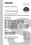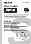
1
FILE NO. A05-015
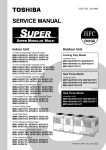
SERVICE MANUAL
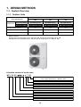
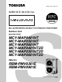
Mini-SUPER MODULAR MULTI SYSTEM AIR CONDITIONER
Outdoor Unit
[Inverter Unit]
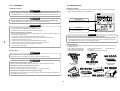
MCY-MAP0401HT
MCY-MAP0501HT
MCY-MAP0601HT
MCY-MAP0401HT2D
MCY-MAP0501HT2D
MCY-MAP0601HT2D
PMV Kit
RBM-PMV0361E
RBM-PMV0901E
PRINTED IN JAPAN, Mar.,2006 ToMo
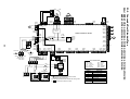
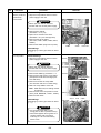
WARNINGS ON REFRIGERANT LEAKAGE
Important
Check of Concentration Limit
The room in which the air conditioner is to be
installed requires a design that in the event of
refrigerant gas leaking out, its concentration will not
exceed a set limit.
The refrigerant R410A which is used in the air
conditioner is safe, without the toxicity or combustibility
of ammonia, and is not restricted by laws to be imposed
which protect the ozone layer. However, since it
contains more than air, it poses the risk of suffocation if
its concentration should rise excessively. Suffocation
from leakage of R410A is almost non-existent. With the
recent increase in the number of high concentration
buildings, however, the installation of multi air
conditioner systems is on the increase because of the
need for effective use of floor space, individual control,
energy conservation by curtailing heat and carrying
power etc.
Most importantly, the multi air conditioner system is able
to replenish a large amount of refrigerant compared with
conventional individual air conditioners. If a single unit of
the multi conditioner system is to be installed in a small
room, select a suitable model and installation procedure
so that if the refrigerant accidentally leaks out, its
concentration does not reach the limit (and in the event
of an emergency, measures can be made before injury
can occur).
In a room where the concentration may exceed the limit,
create an opening with adjacent rooms, or install
mechanical ventilation combined with a gas leak
detection device.
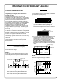
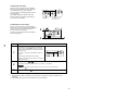
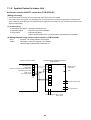
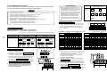
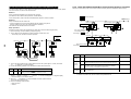
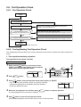
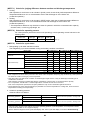
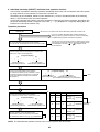
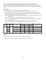
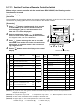
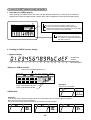
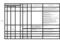
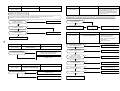
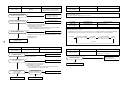
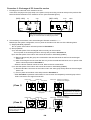
The concentration is as given below.
Total amount of refrigerant (kg)
Min. volume of the indoor unit installed room (m³)
≤ Concentration limit (kg/m³)
NOTE 2 :
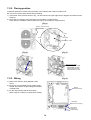
The standards for minimum room volume are as follows.
(1) No partition (shaded portion)
(2) When there is an effective opening with the adjacent
room for ventilation of leaking refrigerant gas
(opening without a door, or an opening 0.15% or
larger than the respective floor spaces at the top or
bottom of the door).
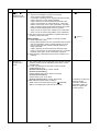
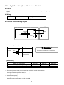
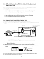
Outdoor unit
Refrigerant piping
Indoor unit
(3) If an indoor unit is installed in each partitioned room
and the refrigerant piping is interconnected, the
smallest room of course becomes the object. But
when a mechanical ventilation is installed
interlocked with a gas leakage detector in the
smallest room where the density limit is exceeded,
the volume of the next smallest room becomes the
object.
Refrigerant piping
Outdoor unit
The concentration limit of R410A which is used in multi
air conditioners is 0.3kg/m³.
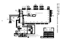
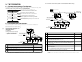
NOTE 1 :
If there are 2 or more refrigerating systems in a single
refrigerating device, the amounts of refrigerant should
be as charged in each independent device.
e.g., charged
amount (10kg)
Outdoor unit
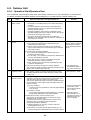
e.g.,
charged amount (15kg)
Very
small
room
Indoor unit
Small
room
Medium
room
Large room
Mechanical ventilation device - Gas leak detector
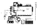
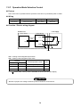
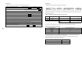
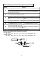
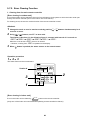
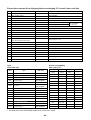
NOTE 3 :
The minimum indoor floor area compared with the
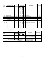
amount of refrigerant is roughly as follows:
(When the ceiling is 2.7m high)
40
m² 35
Room A Room B Room C Room D Room E Room F
Indoor unit
For the amount of charge in this example:
The possible amount of leaked refrigerant gas in
rooms A, B and C is 10kg.
The possible amount of leaked refrigerant gas in
rooms D, E and F is 15kg.
Min. indoor floor area
30
25
Range below the
density limit
of 0.3 kg/m³
(countermeasures
not needed)
20
15
10
Range above
the density limit
of 0.3 kg/m³
(countermeasures
needed)
5
0
10
20
30
Total amount of refrigerant
kg
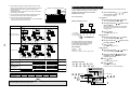
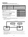
CONTENTS
SAFETY CAUTION ............................................................................................ 4
1. DESIGN METHODS ................................................................................ 10
2. WIRING DIAGRAM ................................................................................. 18
3. PARTS RATING ...................................................................................... 33
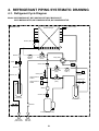
4. REFRIGERANT PIPING SYSTEMATIC DRAWING ............................... 51
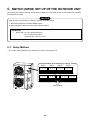
5. SWITCH (SW08) SET UP OF THE OUTDOOR UNIT ............................. 54
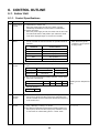
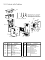
6. CONTROL OUTLINE .............................................................................. 55
7. APPLIED CONTROL .............................................................................. 63
8. PMV KIT OUT LINE ................................................................................ 77
9. TEST OPERATION ................................................................................. 79
10. TROUBLESHOOTING .......................................................................... 108
11. CONFIGURATION OF CONTROL CIRCUIT ........................................ 152
12. BACKUP OPERATIONS (EMERGENCY OPERATION)....................... 166
13. REPLACING COMPRESSOR............................................................... 167
14. REPLACING PROCEDURE OF PARTS ............................................... 168
15. P.C. BOARD .......................................................................................... 182
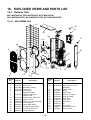
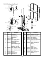
16. EXPLODED VIEWS AND PARTS LIST ................................................. 188
3
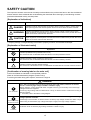
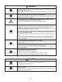
SAFETY CAUTION
The important contents concerned to the safety are described on the product itself and on this Service Manual.
Please read this Service Manual after understanding the described items thoroughly in the following contents
(Indications/Illustrated marks), and keep them.
[Explanation of indications]
Indication
Explanation
DANGER
Indicates contents assumed that an imminent danger causing a death or serious injury of
the repair engineers and the third parties when an incorrect work has been executed.
WARNING
Indicates possibilities assumed that a danger causing a death or serious injury of the
repair engineers, the third parties, and the users due to troubles of the product after work
when an incorrect work has been executed.
CAUTION
Indicates contents assumed that an injury or property damage (∗) may be caused on the
repair engineers, the third parties, and the users due to troubles of the product after work
when an incorrect work has been executed.
∗ Property damage : Enlarged damage concerned to property, furniture, and domestic animal/pet
[Explanation of illustrated marks]
Mark
Explanation
Indicates prohibited items (Forbidden items to do)
The sentences near an illustrated mark describe the concrete prohibited contents.
Indicates mandatory items (Compulsory items to do)
The sentences near an illustrated mark describe the concrete mandatory contents.
Indicates cautions (including danger/warning)
The sentences or illustration near or in an illustrated mark describe the concrete cautious contents.
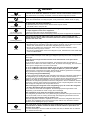
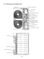
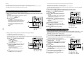
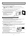
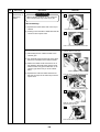
[Confirmation of warning label on the main unit]
Confirm that labels are indicated on the specified positions
(Refer to the Parts disassembly diagram (Outdoor unit).)
If removing the label during parts replace, stick it as the original.
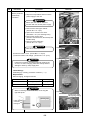
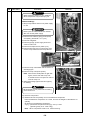
DANGER
Turn off breaker.
Execute discharge
between terminals.
Turn “OFF” the breaker before removing the front panel and cabinet, otherwise an electric
shock is caused by high voltage resulted in a death or injury.
During operation, a high voltage with 400V or higher of circuit (∗) at secondary circuit of the highvoltage transformer is applied.
If touching a high voltage with the naked hands or body, an electric shock is caused even if using an
electric insulator.
∗ : For details, refer to the electric wiring diagram.
When removing the front panel or cabinet, execute short-circuit and discharge between highvoltage capacitor terminals.
If discharge is not executed, an electric shock is caused by high voltage resulted in a death or injury.
After turning off the breaker, high voltage also keeps to apply to the high-voltage capacitor.
Do not turn on the breaker under condition that the front panel and cabinet are removed.
An electric shock is caused by high voltage resulted in a death or injury.
Prohibition
4
WARNING
Check earth wires.
Before troubleshooting or repair work, check the earth wire is connected to the earth
terminals of the main unit, otherwise an electric shock is caused when a leak occurs.
If the earth wire is not correctly connected, contact an electric engineer for rework.
Do not modify the products.
Do not also disassemble or modify the parts. It may cause a fire, electric shock or injury.
Prohibition of modification.
Use specified parts.
Do not bring a child
close to the equipment.
For spare parts, use those specified (*).
If unspecified parts are used, a fire or electric shock may be caused.
∗: For details, refer to the parts list.
Before troubleshooting or repair work, do not bring a third party (a child, etc.) except
the repair engineers close to the equipment.
It causes an injury with tools or disassembled parts.
Please inform the users so that the third party (a child, etc.) does not approach the equipment.
Connect the cut-off lead cables with crimp contact, etc, put the closed end side
upward and then apply a water-cut method, otherwise a leak or production of fire is
caused at the users’ side.
Insulating measures
No fire
When repairing the refrigerating cycle, take the following measures.
1) Be attentive to fire around the cycle. When using a gas stove, etc, be sure to put out fire
before work; otherwise the oil mixed with refrigerant gas may catch fire.
2) Do not use a welder in the closed room. When using it without ventilation, carbon
monoxide poisoning may be caused.
3) Do not bring inflammables close to the refrigerant cycle, otherwise fire of the welder may
catch the inflammables.
(For more details, please refer Page 7 to Page 9)
This air conditioner adopts a new HFC type refrigerant (R410A) which does not deplete the
ozone layer.
Check the used refrigerant name and use tools and materials of the parts which
match with it.
For the products which use R410A refrigerant, the refrigerant name is indicated at a
position on the outdoor unit where is easy to see. To prevent miss-charging, the route of the
service port is changed from one of the former R22.
For an air conditioner which uses R410A, never use other refrigerant than R410A.
For an air conditioner which uses other refrigerant (R22, etc.), never use R410A.
If different types of refrigerant are mixed, abnormal high pressure generates in the refrigerating cycle and an injury due to breakage may be caused.
Refrigerant
Do not charge refrigerant additionally.
If charging refrigerant additionally when refrigerant gas leaks, the refrigerant composition in
the refrigerating cycle changes resulted in change of air conditioner characteristics or
refrigerant over the specified standard amount is charged and an abnormal high pressure is
applied to the inside of the refrigerating cycle resulted in cause of breakage or injury.
Therefore if the refrigerant gas leaks, recover the refrigerant in the air conditioner, execute
vacuuming, and then newly recharge the specified amount of liquid refrigerant. In this time,
never charge the refrigerant over the specified amount.
When recharging the refrigerant in the refrigerating cycle, do not mix the refrigerant
or air other than R410A into the specified refrigerant.
If air or others is mixed with the refrigerant, abnormal high pressure generates in the
refrigerating cycle resulted in cause of injury due to breakage.
After installation work, check the refrigerant gas does not leak.
If the refrigerant gas leaks in the room, poisonous gas generates when gas touches to fire
such as fan heater, stove or cocking stove though the refrigerant gas itself is innocuous.
Never recover the refrigerant into the outdoor unit.
When the equipment is moved or repaired, be sure to recover the refrigerant with recovering device. The refrigerant cannot be recovered in the outdoor unit; otherwise a serious
accident such as breakage or injury is caused.
Assembly/Cabling
After repair work, surely assemble the disassembled parts, and connect and lead the
removed cables as before. Perform the work so that the cabinet or panel does not
catch the inner cables.
If incorrect assembly or incorrect cable connection was done, a disaster such as a leak or
fire is caused at user’s side.
5
WARNING
Insulator check
Ventilation
After the work has finished, be sure to use an insulation tester set (500V mugger) to
Ω or more between the charge section and the non-charge
check the resistance is 2MΩ
metal section (Earth position).
If the resistance value is low, a disaster such as a leak or electric shock is caused at user’s
side.
When the refrigerant gas leaks during work, execute ventilation.
If the refrigerant gas touches to a fire, poisonous gas generates. A case of leakage of the
refrigerant and the closed room full with gas is dangerous because a shortage of oxygen
occurs. Be sure to execute ventilation.
When checking the circuit inevitably under condition of the power-ON, use rubber
gloves and others not to touch to the charging section.
If touching to the charging section, an electric shock may be caused.
Be attentive to
electric shock
When the refrigerant gas leaks, find up the leaked position and repair it surely.
If the leaked position cannot be found up and the repair work is interrupted, pump-down
and tighten the service valve, otherwise the refrigerant gas may leak into the room.
The poisonous gas generates when gas touches to fire such as fan heater, stove or cocking
stove though the refrigerant gas itself is innocuous.
Compulsion
When installing equipment which includes a large amount of charged refrigerant such
as a multi air conditioner in a sub-room, it is necessary that the density does not the
limit even if the refrigerant leaks.
If the refrigerant leaks and exceeds the limit density, an accident of shortage of oxygen is
caused.
For the installation/moving/reinstallation work, follow to the Installation Manual.
If an incorrect installation is done, a trouble of the refrigerating cycle, water leak, electric
shock or fire is caused.
After repair work has finished, check there is no trouble.
If check is not executed, a fire, electric shock or injury may be caused. For a check, turn off
the power breaker.
Check after rerair
Check after reinstallation
After repair work (installation of front panel and cabinet) has finished, execute a test
run to check there is no generation of smoke or abnormal sound.
If check is not executed, a fire or an electric shock is caused. Before test run, install the
front panel and cabinet.
Check the following items after reinstallation.
1) The earth wire is correctly connected.
2) The power cord is not caught in the product.
3) There is no inclination or unsteadiness and the installation is stable.
If check is not executed, a fire, an electric shock or an injury is caused.
CAUTION
Put on gloves
Cooling check
∗) during repair work.
Be sure to put on gloves (∗
If not putting on gloves, an injury may be caused with the parts, etc.
(∗) Heavy gloves such as work gloves
When the power was turned on, start to work after the equipment has been
sufficiently cooled.
As temperature of the compressor pipes and others became high due to cooling/heating
operation, a burn may be caused.
6
• New Refrigerant (R410A)
1. Safety Caution Concerned to New Refrigerant
The pressure of R410A is high 1.6 times of that of the former refrigerant (R22). Accompanied with change of
refrigerant, the refrigerating oil has been also changed. Therefore, be sure that water, dust, the former
refrigerant or the former refrigerating oil is not mixed into the refrigerating cycle of the air conditioner with
new refrigerant during installation work or service work. If an incorrect work or incorrect service is performed, there is a possibility to cause a serious accident. Use the tools and materials exclusive to R410A to
purpose a safe work.
2. Cautions on Installation/Service
1) Do not mix the other refrigerant or refrigerating oil.
For the tools exclusive to R410A, shapes of all the joints including the service port differ from those of the
former refrigerant in order to prevent mixture of them.
2) As the use pressure of the new refrigerant is high, use material thickness of the pipe and tools which are
specified for R410A.
3) In the installation time, use clean pipe materials and work with great attention so that water and others do
not mix in because pipes are affected by impurities such as water, oxide scales, oil, etc.
Use the clean pipes.
Be sure to brazing with flowing nitrogen gas. (Never use gas other than nitrogen gas.)
4) For the earth protection, use a vacuum pump for air purge.
5) R410A refrigerant is azeotropic mixture type refrigerant. Therefore use liquid type to charge the refrigerant. (If using gas for charging, composition of the refrigerant changes and then characteristics of the air
conditioner change.)
3. Pipe Materials
For the refrigerant pipes, copper pipe and joints are mainly used. It is necessary to select the most appropriate pipes to conform to the standard. Use clean material in which impurities adhere inside of pipe or joint to a
minimum.
1) Copper pipe
<Piping>
The pipe thickness, flare finishing size, flare nut and others differ according to a refrigerant type.
When using a long copper pipe for R410A, it is recommended to select “Copper or copper-base pipe without
seam” and one with bonded oil amount 40mg/10m or less. Also do not use crushed, deformed, discolored
(especially inside) pipes. (Impurities cause clogging of expansion valves and capillary tubes.)
<Flare nut>
Use the flare nuts which are attached to the air conditioner unit.
2) Joint
The flare joint and socket joint are used for joints of the copper pipe. The joints are rarely used for installation of the air conditioner. However clear impurities when using them.
7
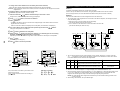
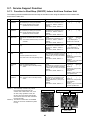
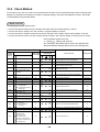
4. Tools
(1) Required Tools for R410A
Mixing of different types of oil may cause generation of sludge, clogging of capillary, etc.
Accordingly, the tools to be used are classified into the following three types.
1) Tools exclusive for R410A (Those which cannot be used for conventional refrigerant (R22))
2) Tools exclusive for R410A, but can be also used for conventional refrigerant (R22)
3) Tools commonly used for R410A and for conventional refrigerant (R22)
The table below shows the tools exclusive for R410A and their interchangeability.
Tools exclusive for R410A (The following tools for R410A are required.)
Tools whose specifications are changed for R410A and their interchangeability
R410A
air conditioner installation
No.
Usage
Used tool
Conventional air
conditioner installation
Existence of
new equipment
for R410A
Whether conventional
equipment can be
used
Whether new equipment
can be used with
conventional refrigerant
Flare tool
Pipe flaring
Yes
*(Note 1)
Yes
Copper pipe gauge for
adjusting projection
margin
Flaring by conventional
flare tool
Yes
*(Note 1)
*(Note 1)
Torque wrench
Connection of flare nut
Yes
No
No
Gauge manifold
Yes
No
No
Charge hose
Evacuating, refrigerant
charge, run check, etc.
Vacuum pump adapter
Vacuum evacuating
Yes
No
Yes
Electronic balance for
refrigerant charging
Refrigerant charge
Yes
Yes
Yes
Refrigerant cylinder
Refrigerant charge
Yes
No
No
Leakage detector
Gas leakage check
Yes
No
Yes
Charging cylinder
Refrigerant charge
(Note 2)
No
No
(Note 1) When flaring is carried out for R410A using the conventional flare tools, adjustment of projection
margin is necessary. For this adjustment, a copper pipe gauge, etc. are necessary.
(Note 2) Charging cylinder for R410A is being currently developed.
General tools (Conventional tools can be used.)
In addition to the above exclusive tools, the following equipments which serve also for R22 are necessary
as the general tools.
1) Vacuum pump
Use vacuum pump by
attaching vacuum pump adapter.
2) Torque wrench
3) Pipe cutter
4) Reamer
5) Pipe bender
6)
7)
8)
9)
10)
11)
12)
Level vial
Screwdriver (+, –)
Spanner or Monkey wrench
Hole core drill
Hexagon wrench (Opposite side 4mm)
Tape measure
Metal saw
Also prepare the following equipments for other installation method and run check.
1) Clamp meter
2) Thermometer
3) Insulation resistance tester (Megger)
4) Electroscope (Volt meter)
8
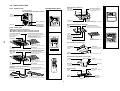
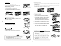
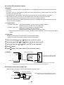
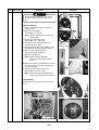
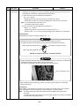
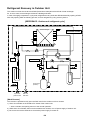
5. Recharge of Refrigerant
When recharge of the refrigerant is required, charge the new refrigerant with the specified amount in the
procedure as described below.
Recover the refrigerant and check there is no refrigerant in the
equipment.
Leave it as it is for 1 to 2 minutes and check the indicator
of the compound gauge does not return.
Connect the charge hose to the packed valve service ports at gas
side, liquid side of the outdoor unit.
Set the refrigerant cylinder on the electronic balance,
connect the charge hose to connecting ports of the
cylinder and the gauge manifold, and then charge the
liquid refrigerant from the service port at liquid side.
(Shield with the gauge manifold so that refrigerant does
not flow to gas side.)
Connect the charge hose to vacuum pump adaptor.
Open the packed valves fully at liquid and gas sides, and then return
the valve at gas side a little to the closed side.
Open fully PMV of the outdoor unit.
• Turn on power of the outdoor unit.
• Short CN30 on I/F P.C. board of the outdoor unit.
• Turn off power of the outdoor unit within 2 minutes after shorting CN30.
LowHighpressure gauge pressure gauge
Open fully the handle on the Low side of the gauge manifold, and
then turn on the power of vacuum pump for vacuuming.
Connected to
indoor unit
Valve fully closed
(gas side)
Main
Center unit
pipe
When the pressure has lowered until indication of the compound
gauge pointed –0.1MPa (–76cmHg), open fully the handle Low and
turn off the power of vacuum pump.
Brazed
Fully
tightened
Service
port
Ø6.4
Copper pipe
VL
VH Gauge
manifold
Reducing
valve
Service port
Never charge the refrigerant over the specified amount.
Do not charge the additional refrigerant.
If charging refrigerant additionally when refrigerant gas
leaks, the refrigerant composition in the refrigerating cycle
changes resulted in change of air conditioner characteristics or refrigerant over the specified standard amount is
charged and an abnormal high pressure is applied to the
inside of the refrigerating cycle resulted in cause of
breakage or injury.
Valve fully closed
(liquid side)
Nitrogen
gas
Ø6.4
Copper pipe
Connected to other
terminal units
4mm-hexagonal wrench is required.
Set the equipment so that liquid refrigerant can be charged.
When using a cylinder with siphon pipe, liquid can be charged without inverting the cylinder.
[ Cylinder with siphon ]
[ Cylinder without siphon ]
Gauge manifold
Gauge manifold
OUTDOOR unit
Electronic
balance
6. Environmental concern
Refrigerant
cylinder
Refrigerant
cylinder
Siphon
OUTDOOR unit
Electronic
balance
R410A refrigerant is consisted with HFC mixed refrigerant.
Therefore if the refrigerant gas is charged, the composition
of the charged refrigerant changes and characteristics of
the equipment changes.
Use “Vacuum pump method” for an air purge (Discharge of air in the connecting pipe) in installation time.
• Do not discharge flon gas into the air to protect the earth environment.
• Using the vacuum pump method, clear the remaining air (Nitrogen, etc.) in the unit. If the air remains, the
pressure in the refrigerating cycle becomes abnormally high and an injury could occur through failure of
the product.
9
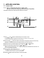
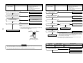
1. DESIGN METHODS
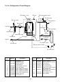
1-1. System Overview
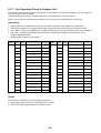
1-1-1. Outdoor Units
Inverter unit
Corresponding HP
4HP
5HP
6HP
Heat pump (50Hz)
MCY-MAP0401HT
MCY-MAP0501HT
MCY-MAP0601HT
Heat pump (60Hz)
MCY-MAP0401HT2D
MCY-MAP0501HT2D
MCY-MAP0601HT2D
Cooling capacity (kW) ∗1
12.1
14.0
15.5
Heating capacity (kW) ∗1
12.5
16.0
18.0
6
8
9
Model name
No.of connectable indoor units
∗1 Rated conditions
Cooling:Indoor air temperature 27°C DB/19°C WB, Outdoor air temperature 35°C DB
Heating:Indoor air temperature 20°C DB, Outdoor air temperature 7°C DB/6°C WB
Allocation standard of model name
MCY- M AP
H T 2D
No mark : Power supply specification, 1Ø/220/230/240V (50Hz)
2D
: Power supply specification, 1Ø/220V, 60Hz
T : Inverter unit
H : Heat pump
Development number
Capacity rank HP × 10
R410A
M : Individual unit
Multi Compact type
10
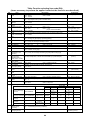
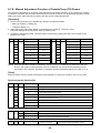
1-1-2. Indoor Units
Type
4-way Air Discharge
Cassette Type
Compact 4-way
Air Discharge
(600 × 600) Type
2-way Air Discharge
Cassette Type
1-way Air Discharge
Cassette Type
Concealed Duct
Standard Type
Slim Duct Type
Concealed Duct
High Static
Pressure Type
Under Ceilling Type
Appearance
Model name
Capacity
rank
Capacity
code
Cooling
capacity (kW)
Heating
capacity (kW)
PMV Kit
MMU-AP0091H
009 type
1.00
2.8
3.2
——
MMU-AP0121H
012 type
1.25
3.6
4.0
——
MMU-AP0151H
015 type
1.70
4.5
5.0
——
MMU-AP0181H
018 type
2.00
5.6
6.3
——
MMU-AP0241H
024 type
2.50
7.1
8.0
——
MMU-AP0271H
027 type
3.00
8.0
9.0
——
MMU-AP0301H
030 type
3.20
9.0
10.0
——
MMU-AP0361H
036 type
4.00
11.2
12.5
——
MMU-AP0481H
048 type
5.00
14.0
16.0
——
MMU-AP0071MH
007 type
0.80
2.2
2.5
Available
MMU-AP0091MH
009 type
1.00
2.8
3.2
Available
MMU-AP0121MH
012 type
1.25
3.6
4.0
Available
MMU-AP0151MH
015 type
1.70
4.5
5.0
Available
MMU-AP0181MH
018 type
2.00
5.6
6.3
Available
MMU-AP0071WH
007 type
0.80
2.2
2.5
——
MMU-AP0091WH
009 type
1.00
2.8
3.2
——
MMU-AP0121WH
012 type
1.25
3.6
4.0
——
MMU-AP0151WH
015 type
1.70
4.5
5.0
——
MMU-AP0181WH
018 type
2.00
5.6
6.3
——
MMU-AP0241WH
024 type
2.50
7.1
8.0
——
MMU-AP0271WH
027 type
3.00
8.0
9.0
——
MMU-AP0301WH
030 type
3.20
9.0
10.0
——
MMU-AP0071YH
007 type
0.80
2.2
2.5
Available
MMU-AP0091YH
009 type
1.00
2.8
3.2
Available
MMU-AP0121YH
012 type
1.25
3.6
4.0
Available
MMU-AP0152SH
015 type
1.70
4.5
5.0
Available
MMU-AP0182SH
018 type
2.00
5.6
6.3
Available
MMU-AP0242SH
024 type
2.50
7.1
8.0
Available
MMD-AP0071BH
007 type
0.80
2.2
2.5
——
MMD-AP0091BH
009 type
1.00
2.8
3.2
——
MMD-AP0121BH
012 type
1.25
3.6
4.0
——
MMD-AP0151BH
015 type
1.70
4.5
5.0
——
MMD-AP0181BH
018 type
2.00
5.6
6.3
——
MMD-AP0241BH
024 type
2.50
7.1
8.0
——
MMD-AP0271BH
027 type
3.00
8.0
9.0
——
MMD-AP0301BH
030 type
3.20
9.0
10.0
——
MMD-AP0361BH
036 type
4.00
11.2
12.5
——
MMD-AP0481BH
048 type
5.00
14.0
16.0
——
MMD-AP0071SPH
007 type
0.80
2.2
2.5
Available
MMD-AP0091SPH
009 type
1.00
2.8
3.2
Available
MMD-AP0121SPH
012 type
1.25
3.6
4.0
Available
MMD-AP0151SPH
015 type
1.70
4.5
5.0
Available
MMD-AP0181SPH
018 type
2.00
5.6
6.3
Available
MMD-AP0181H
018 type
2.00
5.6
6.3
——
MMD-AP0241H
024 type
2.50
7.1
8.0
——
MMD-AP0271H
027 type
3.00
8.0
9.0
——
MMD-AP0361H
036 type
4.00
11.2
10.0
——
MMD-AP0481H
048 type
5.00
14.0
16.0
——
MMC-AP0151H
015 type
1.70
4.5
5.0
——
MMC-AP0181H
018 type
2.00
5.6
6.3
——
MMC-AP0241H
024 type
2.50
7.1
8.0
——
MMC-AP0271H
027 type
3.00
8.0
9.0
——
MMC-AP0361H
036 type
4.00
11.2
12.5
——
MMC-AP0481H
048 type
5.00
14.0
16.0
——
11
Type
Capacity
rank
Capacity
code
Cooling
capacity (kW)
Heating
capacity (kW)
PMV Kit
MMK-AP0071H
007 type
0.80
2.2
2.5
Available
MMK-AP0091H
009 type
1.00
2.8
3.2
Available
MMK-AP0121H
012 type
1.25
3.6
4.0
Available
MMK-AP0151H
015 type
1.70
4.5
5.0
Available
MMK-AP0181H
018 type
2.00
5.6
6.3
Available
MMK-AP0241H
024 type
2.50
7.1
8.0
Available
MMK-AP0072H
007 type
0.80
2.2
2.5
Available
MMK-AP0092H
009 type
1.00
2.8
3.2
Available
MMK-AP0122H
012 type
1.25
3.6
4.0
Available
MML-AP0071H
007 type
0.80
2.2
2.5
Available
MML-AP0091H
009 type
1.00
2.8
3.2
Available
MML-AP0121H
012 type
1.25
3.6
4.0
Available
MML-AP0151H
015 type
1.70
4.5
5.0
Available
MML-AP0181H
018 type
2.00
5.6
6.3
Available
MML-AP0241H
024 type
2.50
7.1
8.0
Available
MML-AP0071BH
007 type
0.80
2.2
2.5
——
MML-AP0091BH
009 type
1.00
2.8
3.2
——
MML-AP0121BH
012 type
1.25
3.6
4.0
——
MML-AP0151BH
015 type
1.70
4.5
5.0
——
MML-AP0181BH
018 type
2.00
5.6
6.3
——
MML-AP0241BH
024 type
2.50
7.1
8.0
——
MMF-AP0151H
015 type
1.70
4.5
5.0
——
MMF-AP0181H
018 type
2.00
5.6
6.3
——
MMF-AP0241H
024 type
2.50
7.1
8.0
——
MMF-AP0271H
027 type
3.00
8.0
9.0
——
MMF-AP0361H
036 type
4.00
11.2
10.0
——
MMF-AP0481H
048 type
5.00
14.0
16.0
——
Model name
Appearance
High Wall Type
(1 series)
High Wall Type
(2 series)
Floor Standing
Cabinet Type
Floor Standing
Concealed Type
Floor Standing Type
Allocation standard of model name
MM
- AP
H C : China model
H : Heat pump type
M : Compact 4-way Cassete Type
W : 2-way Cassette Type
S : 1-way Cassette Type
Y : Small sized 1-way Cassette Type
B : Built-in Type (Built-in Duct Type) (Floor concealed type)
SP(S) : Slim Duct Type
Development series No.
Based on the cooling capacity (Btu/h) /1,000
R410A
U
C
D
K
L
F
: Cassette Type
: Under Ceiling Type
: Duct Type
: High Wall Type
: Floor Type (Cabinet type) (Concealed type)
: Floor Standing Type
MM : Modular Multi type
12
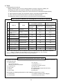
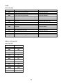
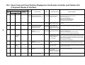
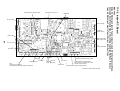
1-1-3. Branching Joints and Headers *1
Model name
Usage
RBM-BY53E
Indoor unit capacity code (*2) :
Total below 6.4
RBM-BY103E
Indoor unit capacity code (*2) :
Total 6.4 or more and below 7.8
4-branching header
RBM-HY1043E
Indoor unit capacity code (*2) :
Total below 7.8
8-branching header
RBM-HY1083E
Indoor unit capacity code (*2) :
Total below 7.8
Appearance
Y-shape branching joint
*1 If total capacity code value of indoor unit exceeds that of outdoor unit, apply code of outdoor unit.
*2 “Capacity code” can be obtained. (capacity code is not actual capacity)
*3 When using Y-shape branching joint for 1st branching, select according to the capacity code of outdoor unit.
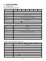
1-1-4. PMV Kit
Model name
Indoor unit capacity type
RBM-PMV0361E
007, 009, 012 type
RBM-PMV0901E
015, 018, 024 type
13
Appearance
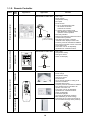
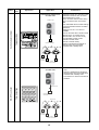
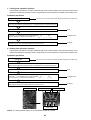
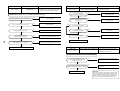
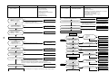
1-1-5. Remote Controller
Name
Model
name
Appearance
Function
Application
RBC- AMT31E
Wired remote Wired remote
controller
controller
In case of control by
2 remote controllers
(
)
RBC- AS21E2
Connected to indoor unit
TEST
SETTING
ûC
ûF
•
•
•
•
•
Start / Stop
Mode Change
Temperature setting
Fan speed
Timer function
1) On or off elapsed timer with
30 minutes increments.
Automatic off function.
2) Weekly when combined with
RBC-EXW21E2 weekly schedule
operation can be operated.
• Filter dirty indicator
Displays automatically maintenance time
of indoor filter by flashes.
• Self-diagnosis function. Pressing
“CHECK” button displays status code.
• Control by 2 remote controllers is available.
Two remote controllers can be connected
to one indoor unit.
The indoor unit can be separately
operated from a different location.
•
•
•
•
Start / Stop
Temperature setting
Change of air flow
Check code display
Simple remote controller
Start / Stop
Mode change
Temperature setting
Change of air flow
Timer function
On or off timer operation, setting in 30
minutes increments.
Automatic Off function.
• Control by 2 remote controllers is available.
Two wireless remote controllers can
operate one indoor unit.
The indoor unit can be separately
operated from a different location.
• Check code display
TCB-AX21U(W)-E2
(for 4-way air discharge cassette)
RBC-AX22CE2 (for under ceiling)
TCB-AX21-E2 (for other units except for
the concealed duct high static pressure)
RBC-AX22CE2
TCB-AX21E2
•
•
•
•
•
TCB- AX21U(W)-E2
Wireless remote controller kit
Simple wired remote controller
Wired remote controller
Connected to indoor unit
14
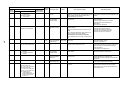
Name
Model
name
Appearance
Application
Performance
Connected to outdoor unit
or indoor unit
Individual control up to 64 indoor units.
Individual control for max. 64 indoor
units divided into 4 zones.
(Up to 16 indoor units for each zone)
Up to 16 outdoor units are connectable.
Four selectable central control settings
to restrict individual remote controller
operations.
Setting for one of 1 to 4 zones is
available.
Can be used with other central control
devices (Up to 10 central control
devices with in one control circuit)
Two selectable control modes
(Central controller mode.
Remote controller mode)
Setting of simultaneous ON/OFF 3
times for each day of the week
combined with a weekly timer.
TCB- SC642TLE2
Central remote controller
Outdoor unit
ZONE
ALL
ZONE
GROUP
CODE
No.
1234
SET DATA
SETTING
R.C.
UNIT No.
TEST
No.
Central
remote controller
GROUP
SELECT
ZONE
CL
SET
Central
remote
controller
Indoor
remote controller
Connected to outdoor unit
or indoor unit
TCB- CC163TLE2
ON- OFF controller
Outdoor unit
ON-OFF
controller
Indoor unit
ON-OFF
controller
Indoor
remote controller
15
• Individual control up to 16 indoor
units.
• Setting of simultaneous ON-OFF 3
times for each day of the week when
combined with a weekly timer.
• Connected to 2 remote controllers is
possible.
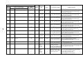
Name
Model
name
Appearance
Application
Performance
Connected to central
remote controller or
wired remote controller
Weekly schedule operation
1) Setting different start / stop time for
each day of the week
2) ON / OFF can be set 3 times a day.
ON
RBC- EXW21E2
Weekly timer
8:00
SuMoTuWeTh Fr Sa
PROGRAM1
PROGRAM2
ERROR
Wired
remote controller
Weekly
timer
PROGRAM3
WEEKLY TIMER
Outdoor unit
Central
remote controller
16
Weekly
timer
OFF ON
OFF ON
OFF
12:00 13:00 18:00 19:00 21:00
3) “CHECK“ “PROGRAM” “DAY” button
copying of settings easy.
4) Two different schedules for a week
can be specified.
(Summer schedule and winter
schedule, etc.)
5) “CANCEL” “DAY” button enables
holiday setting.
6) If power supply fails, the setting
contents are stored in the memory
for 100 hours.
n Remote controllers
Name
Wired remote controller
Simple wired remote controller
Weekly timer
CODE No.
SuMoTuWeTh Fr Sa
SET DATA SETTING TEST
SETTING
H
PROGRAM1
˚C
˚F
TEST
UNIT No.
R.C.
No.
PROGRAM2
ERROR
PROGRAM3
TEMP.
Appearance
ON / OFF
WEEKLY TIMER
FILTER
RESET TEST
Model name
TIMER SET
FAN
MODE
TIME
SWING/FIX
VENT
SET
CL
UNIT
RBC-AMT31E
RBC-AS21E2
RBC-EXW21E2
Wireless remote controller kit
Name
Receiver section
ADR
Receiver section
mounted separately
Receiver section
ADR
ADR
Appearance
Model name
RBC-AX21U (W)-E2
RBC-AX22CE2
TCB-AX21E2
Type
4-way Air Discharge
Cassette type
Under Ceiling type
1-way Air Discharge Cassette
type (MMU-AP✽✽✽2SH Series)
Separate sensor type
Name
Central remote controller
ON, OFF controller
ZONE
ALL
ZONE
GROUP
CODE
No.
1234
SET DATA
SETTING
R.C.
UNIT No.
TEST
No.
Appearance
GROUP
SELECT
ZONE
CL
SET
Model name
TCB-SC642TLE2
TCB-CC163TLE2
Type
64 system center controller
—
17
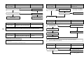
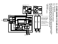
1
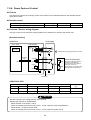
CN304
(GRY) 2
3
RED
3
1 CN34
3 2 1 (RED)
RY302
Motor drive
circuit
RY303
Fuse
T6.3A
250V~
1 1
3 3
BLK
1 2 3 4 5 CN33
1 2 3 4 5 (WHI)
1 2 3 4 5 6 CN82
1 2 3 4 5 6 (BLU)
~
+
~
–
Indoor control P.C. board
MCC-1402
Fuse
T3.15A
250V~
Power
supply
circuit
CN67
(BLK) 2 2
WHI
FS
DC20V
DC15V
DC12V
DC7V
P301
Flow selector
unit earth
CN66 1
screw
(WHI) 2
CN44 1
(BLN) 2
CN50
(WHI)
1 2 3 4 5
Earth screw
1 2
CN61
(YEL)
T10 1 2 3 4 5 6
Parts name
Fan motor
Indoor temp sensor
Temp sensor
Temp sensor
Temp sensor
Louver motor
Drain pump motor
Float switch
Drain control relay
Pulse Motor Valve
CN60
(WHI)
CN81
(BLK)
CN40
(BLU)
CN41
(BLU)
1 2 3 4 5 6
1 2 3 4 5
1 2
1 2
1 2 3
1 2 3
(Option)
BLU
BLU
(Fandrive)
Power supply
Single phase
220-240V 50Hz
220V 60Hz
Symbol
FM
TA
TC1
TCJ
TC2
LM1, LM2
DM
FS
RY302
PMV
CN32
(WHI)
CN309
(YEL)
1 1
2 2
CN102
(RED)
1 1
2 2
CN101
(BLK)
1 1
2 2
CN100
(BRN)
1 1
2 2
3 3
CN80
(GRN)
1
2 PNL
3
CN73
(RED)
1 EXCT
2
CN20 CN70
(BLU) (WHI)
1 2 3 4 5
1 2 3
1 2 3
BLK
R(L) S(N)
Closed end
connector
BLK
18
RED
WHI
Indoor unit
CN104
(YEL)
TR
1.
indicates the terminal block, letter at inside
indicates the terminal number.
2. A dotted line and broken line indicate the wiring at site.
3.
indicates the control P.C. board.
U1 U2
CN01 1 2 Network adaptor
(WHI) 1 2 (Option)
A B
BLK
WHI
U1 U2
Outdoor unit
WHI
CN1
(WHI)
Color identification
RED
WHI
YEL
BLU
BRN
: RED
: WHITE
: YELLOW
: BLUE
: BROWN
BLK
GRY
PNK
ORN
GRN
: BLACK
: GRAY
: PINK
: ORANGE
: GREEN
BLK
CN001
(WHI)
1 2
1 2
1 2
1 2
Wired remote
controller
Adaptor for wireless
remote controller
3 3
2 2
1 1
CN02
(BLU)
Network
adaptor
P.C. board
MCC-1401
1 2 CN03
1 2 (RED)
X Y
TA
TCJ
TC2
TC1
1 Filter input
2
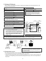
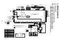
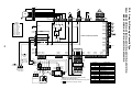
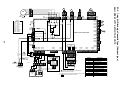
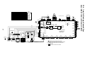
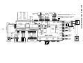
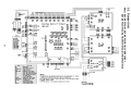
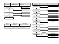
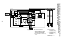
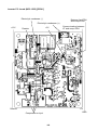
2. WIRING DIAGRAM
1 1
2 2
3 3
DM
1 2 3 4 5
1 2 3 4 5
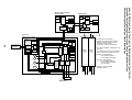
2-1. Indoor Unit
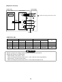
5 4 3 2 1 CN334 1 2 3 4 5 CN333
5 4 3 2 1 (BLU) 1 2 3 4 5 (WHI)
1 2 3 4 5
1 2 3 4 5
2-1-1. 4-way Air Discharge Cassette Type
6 4 3 1 2 5
6 4 3 1 2 5
CN68
(BLU)
LM1
LM2
1 2 3 4 5
1 2 3 4 5
Model: MMU-AP0091H, AP0121H, AP0151H, AP0181H, AP0241H,
MMU-AP0271H, AP0301H, AP0361H, AP0481H, AP0561H,
MMU-AP0071MH, AP0091MH, AP0121MH, AP0151MH, AP0181MH
PMV
FM
RC
LM
1 2
1 2
DM
YEL
BLU
ORN
BLK
RED
FAN
9 8 7 6 5 4 3 2 1
CN083(WHI) 9 8 7 6 5 4 3 2 1
9
H
Color
indication
M
L
PMV
6 4 3 1 2 5
6 4 3 1 2 5
FS
DP
LM
FS
1 2 3 (BLU) 1 2 3 (GRN) 1 2 3 (RED)
1 2 3 CN068 1 2 3 CN033 1 2 3 CN030
PMV
1 2 3 4 5 6 (BLU)
1 2 3 4 5 6 CN082
UL
RY007
RED : RED
WHI : WHITE
YEL : YELLOW
BLU : BLUE
BLK : BLACK
GRY : GRAY
PNK : PINK
ORN : ORANGE
BRW : BROWN
GRN : GREEN
P301
(BLK)
RY002
RY001
RY006
1
CN304
(GRY) 2
RY005
Fuse
T5.0A
19
CN066 1
(WHI) 2
Power supply
circuit
CN044 1
(BRW) 2
CN040 CN041
(BLU) (BLU)
Indoor unit
Earth screw R(L) S(N)
1 2 3
1 2 3
BLK
BLU
BLU
1 2
1 2
CN050
(WHI)
CN075
(WHI)
CN074
(WHI)
1 2 3 4 5
1 2 3
1 2 3
BLK
Flow selector
unit earth
screw
TR
CN102
(RED)
1 1
2 2
CN101
(BLK)
1 1
2 2
CN100
(BRW)
1 1
2 2
3 3
CN080
(GRN)
1
2 PNL
3
CN073
(RED)
1 EXCT
2
CN070
(WHI)
1 1
2 2
CN081
(BLK)
1
2
3
4
5
Indoor control P.C. board
1 1
2 2
3 3
1 1
2 2 CN067 250V~
(BLK)
3 3
Closed end
connector
1 1
2 2
RY004
3
CN039
(YEL)
CN104
(YEL)
1 2 3 4 5 6
1 2 3 4 5 6
CN061
(YEL)
1 2 3 4 5 6
A B X Y
Network
CN01 1 2 adaptor
(WHI) 1 2 (Option)
3 3
2
1 1
U1 U2
CN1
(WHI)
Outdoor unit
1 2
1 2
Remote controller
1 2
1 2 3 4 5 6
TCJ
TC2
Option
1 2 3 4 5 6 CN02
1 2 3 4 5 6 (YEL)
Line Filter
U1 U2
CN060
(WHI)
Fan drive
Sub P.C. board
MCC-1520
Power supply
Single phase
220-240V 50Hz
220V 60Hz
CN032
(WHI)
TA
CN02
(BLU)
1 1
2 2
MCC-1401
1 2 3 4 5 6 CN01
1 2 3 4 5 6 (WHI)
TR
CN03
(RED)
1.
indicates the terminal block, letter at inside
indicates the terminal number.
2. A dotted line and broken line indicate the wiring at site.
3.
indicates the control P.C. board.
Symbol
FM
RC
TR
LM
TA
TC1,TC2,TCJ
RY001
RY002
RY004
RY005~007
FS
DM
PMV
Parts name
Fan motor
Running capacitor
Transformer
Louver motor
Indoor temp sensor
Temp sensor
Louver control relay
Drain control relay
Heater control relay
Fan motor control relay
Float switch
Drain pump motor
Pulse Motor Valve
TC1
Filter
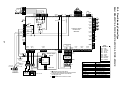
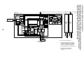
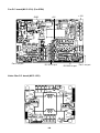
2-1-2. 2-way Air Discharge Cassette Type
1
2
RED
3
4
5
6
7
Model: MMU-AP0071WH, AP0091WH, AP0121WH, AP0151WH, AP0181WH,
MMU-AP0241WH, AP0271WH, AP0301WH, AP0481WH
FM
WHI
1
2
3
4
5
6
7
YEL
BLU
BLK
ORN
1 2 3
1 2 3
H
M
L
FS
2 1
2 1
2 1
2 1
DP
LM
6 4 3 1 2 5
6 4 3 1 2 5
FS
1 2 3 (BLU) 1 2 3 (GRN) 1 2 3 (RED)
1 2 3 CN068 1 2 3 CN033 1 2 3 CN030
FAN
9 8 7 6 5 4 3 2 1
CN083(WHI) 9 8 7 6 5 4 3 2 1
Color
indication
PMV
LM
RED
RC
DM
PMV
1 2 3 4 5 6 (BLU)
1 2 3 4 5 6 CN082
UL
RY007
CN301
(BLK)
RED : RED
WHI : WHITE
YEL : YELLOW
BLU : BLUE
BLK : BLACK
GRY : GRAY
PNK : PINK
ORN : ORANGE
BRW : BROWN
GRN : GREEN
RY002
RY001
RY006
Heater
1
CN304
(GRY) 2
RY005
3 3
1 1
2 2 CN067 Fuse
(BLK) T5.0A
3 3
20
CN066 1
(WHI) 2
Power supply
circuit
CN044 CN040 CN041
(BRW) (BLU) (BLU)
1 2
1 2
WHI
RED
TR
Flow selector
unit earth
screw
1 2
1 2
1 2 3
1
3
1 1
2 2
CN101
(BLK)
1
2
CN100
(BRW)
1 1
2 2
3 3
CN080
(GRN)
1
2 PNL
3
CN073
(RED)
1 EXCT
2
CN070
(WHI)
1 1
Filter
2 2
CN081
(BLK)
1
2
3
4
5
1 2 3 4 5
1 2 3
1 2 3
Network
CN01 1 2 adaptor
(WHI) 1 2 (Option)
1 1
2 2
BLK
BLK
BLU
BLU
WHI
U1 U2
1 2 3 4 5 6
1 2 3 4 5 6
CN061
(YEL)
1 2 3 4 5 6
A B X Y
AI-NET
central control
terminal
Power supply
Single phase
220-240V 50Hz
220V 60Hz
CN060
(WHI)
1 2
1 2 3 4 5 6
Fan drive
CN03
(RED)
Sub P.C. board
MCC-1520
1 2 3 4 5 6 CN01
1 2 3 4 5 6 (WHI)
Network
adaptor
P.C. board
TR
3 2 1 CN02
3 2 1 (BLU)
U1 U2
CN1
(WHI)
Outdoor
unit
CN032
(WHI)
TCJ
TC1
Option
MCC-1401
Line Filter
BLU
CN075
(WHI)
CN074
(WHI)
TA
1 2 3 4 5 6 CN02
1 2 3 4 5 6 (YEL)
BLU
Indoor unit
Earth screw R(L) S(N)
CN050
(WHI)
BLU
Closed end
connector
CN102
(RED)
Indoor control P.C. board
1 1
CN309
(YEL) 2 2
RED
1 1
2 2
RY004
3
AC IN
CN104
(YEL)
1 2
1 2
Remote controller
1.
indicates the terminal block, letter at inside
indicates the terminal number.
2. A dotted line and broken line indicate the wiring at site.
3.
indicates the control P.C. board.
Symbol
FM
RC
TR
LM
TA
TC1,TCJ
RY001
RY002
RY004
RY005~007
FS
DM
PMV
Parts name
Fan motor
Running capacitor
Power transformer
Louver motor
Indoor temp sensor
Temp sensor
Louver motor control relay
Drain pump control relay
Heater control relay
Fan motor control relay
Float switch
Drain pump motor
Pulse Motor Valve
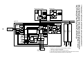
2-1-3. 1-way Air Discharge Cassette Type (Compact type)
FM
1
2
3
4
5
6
Model: MMU-AP0071YH, AP0091YH, AP0121YH
1
2
3
4
5
6
RED : RED
WHI : WHITE
YEL : YELLOW
BLU : BLUE
BLK : BLACK
GRY: GRAY
PNK : PINK
ORN: ORANGE
BRN : BRWN
GRN: GREEN
PMV
FM
CN68
(BLU)
1 1
DM
CN334 5 4
1
(WHI) 5 4 3 2 1
RY302
CN304
(GRY)
RED
WHI
CN67
(BLK)
TR
1 1
2
3 3
WHI
Power supply
single phase
220-240V 50Hz
220V 60Hz
5 CN333
5 (WHI)
1 2 3 4 5 6 CN82
1 2 3 4 5 6 (BLU)
RY303
1 1
3 3
A B
Outdoor
unit
Wired
remote
controller
BLK
CN01
CN02 (WHI)
(BLU) CN03
(RED)
MCC-1401
1 2
1 2
CN001(WHI)
Adapter for
wireless remote
controller
AI-NET
1 2
1 2
X Y
Network adapter
(Option)
BLU
BLK
BLK
FS
1 2 3 4 5 CN33
1 2 3 4 5 (WHI)
1 2
1 2
1 2
1 2
CN112
(WHI)
CN111
(WHI)
CN110
(WHI)
Fuse
T3.15A
250V~
3
21
U1 U2 A B
U1 U2
1 2
1 2
WHI
WHI Closed-end
connector
R(L) S(N)
3
3
CN71
(CHK)
CN72
(DISP)
DC20V
DC15V
DC12V
DC7V
Power
supply
circuit
Fuse
T6.3A 250V~
1
2
CN66
(WHI)
1 2
1 2
CN40
(BLU)
1 1
2
3 3
CN41
(BLU)
Control P.C. board
for indoor unit
MCC-1402
CN309
(YEL)
1
1
3
3
CN50
(WHI)
CN061
(YEL)
CN32
(WHI)
CN60
(WHI)
CN81
(BLK)
CN20
(BLU)
1 2 3 4 5
1 2 3 4 5 6
1 2
Fan
drive
1 2 3 4 5 6
1 2 3 4 5
1 2 3 4 5
T10
1.
1
3
1 2 3
Option
indicates the terminal bolock letter.
Letter at inside indicates the terminal number.
2. A dotted line and broken line indicate the
wiring at side
3.
indicates a control P.C. board.
GRL
CN34
(RED)
CN104
(YEL)
1 1
2 2
CN102
(RED)
1 1
2 2
CN101
(BLK)
1 1
2 2
CN100
(BRW)
P301
BLK
BLU
Indoor unit
earth screw
1
1
1
BLK
RED
1 2 3 4 5
1 2 3 4 5
Motor drive
circuit
3 3
Flow selector unit
earth screw
LM
High ceiling setup
6 4 3 1 2 5
6 4 3 1 2 5
TA
TCJ
TC2
1 1
3 3
CN80
(GRN)
1
2 PNL
3
CN73
(RED)
1
EXCT
2
CN70
(WHI)
1
2
Filter
TC1
2-1-4. 1-way Air Discharge Cassette Type
Color
indication
Parts name
Fan motor
Indoor temp sensor
Temp sensor
Temp sensor
Temp sensor
Louver motor
Drain pump motor
Float switsh
Drain control relay
Pulse motor valve
Transformer
Model: MMU-AP0152SH, AP0182SH, AP0242SH
Symbol
FM
TA
TC1
TCJ
TC2
LM
DM
FS
RY302
PMV
TR
6 4 3 1 2 5
6 4 3 1 2 5
1 2 3
1 2 3
CN68
(BLU)
1 1
2 2
3 3
DM
CN333 1
(WHI) 1
5 4
2 1
5 4 3 2 1
1 1
WHI
1
3
1 2 2
3
1 CN34
3 2 1 (RED)
CN33
1 2 3 4 5 (WHI)
Indoor control P.C. board
~
Fuse
T3.15A
+
250V~
250V~
3 3
BLK
1 2 3 4 5 6 CN82
1 2 3 4 5 6 (BLU)
Motor drive
circuit
Fuse
T6.3A
CN67
(BLK) 2 2
5
5
CN334
(WHI)
RY302
1
CN304
(GRY) 2
3
RED
3
3
FS
–
~
Power
supply
circuit
DC20V
DC15V
DC12V
DC7V
P301
WHI
CN44 1
(BRW) 2
R(L) S(N)
Closed end
connector
Flow selector
unit earth
screw
Earth screw
CN40
(BLU)
CN41
(BLU)
1 2
1 2
1 2 3
1 2 3
BLU
BLU
Indoor unit
WHI
Indoor unit power supply
Single phase
220-240V 50Hz
220V 60Hz
CN50
(WHI)
CN309
(YEL)
1 2 3
1 2 3
TR
U1 U2
A B
BLK
WHI
Outdoor unit
CN1
(WHI)
T10 1 2 3 4 5 6
CN32
(WHI)
CN60
(WHI)
CN81
(BLK)
1 2
1 2 3 4 5 6
1 2 3 4 5
(Fan drive)
(Signal output)
Network
CN01 1 2 adaptor
(WHI) 1 2 (Option)
3 3
2 2
1 1
WHI
U1 U2
1 2 3 4 5
CN61
(YEL)
1 1
2 2
CN102
(RED)
1 1
2 2
CN101
(BLK)
1 1
2 2
CN100
(BRN)
1 1
2 2
3 3
CN80
(GRN)
1
2 PNL
3
CN73
(RED)
1 EXCT
2
CN20 CN70
(BLU) (WHI)
1 2 3 4 5
BLK
Reactor
RED
BLK
22
CN66 1
(WHI) 2
CN104
(YEL)
CN02
(BLU)
Network
adaptor
P.C. board
1 2 CN03
1 2 (RED)
BLK
X Y
CN001
(WHI)
1 2
1 2
1 2
1 2
Wired remote
controller
Adaputor for wired
remote controller
1.
indicates the terminal block, letter at inside
indicates the terminal number.
2. A dotted line and broken line indicate the wiring at site.
3.
indicates the control P.C. board.
Color identification
RED : RED
WHI : WHITE
YEL : YELLOW
BLU : BLUE
BRW : BROWN
Symbol
FM
TA
TC1,TC2,TCJ
DM
FS
RY302
PMV
BLK
GRY
PNK
ORN
GRN
: BLACK
: GRAY
: PINK
: ORANGE
: GREEN
Parts name
Fan motor
Indoor temp sensor
Indoor temp sensor
Drain pump motor
Float switch
Drain pump control relay
Pulse Motor Valve
1
2
TA
TCJ
TC2
TC1
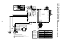
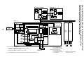
2-1-5. Concealed Duct Standard Type
PMV
1 1
Model: MMD-AP0071BH, AP0091BH, AP0121BH, AP0151BH, AP0181BH, AP0241BH
MMD-AP0271BH, AP0301BH, AP0361BH, AP0481BH, AP0561BH
FM
5 5
4 4
8
DP
(BLK)
RY007
P301
1
CN304
(GRY) 2
H
RY004
M
L
1 2 3
1 2 3
FS
CN030
(RED)
UL
RY002
RY006
1 2
1 2
1 2
1 2
1 2
1 2
TC1
1 2 3 CN100
1 2 3 (BRN)
CN104 CN102 CN101
(YEL) (RED) (BLK)
RY001
3
1 1
CN309
2 2 (YEL)
3 3
Power
supply
circuit
CN066
(WHI)
CN044 CN040 CN041
(BRW) (BLU) (BLU)
1 2
23
TR
1 2
1 2
EMG
OC
CN050
(WHI)
1 2 3
1
3
1 2 3
1 2 3
Network adaptor
(Option)
MCC-1401
CN01 1 2
(WHI) 1 2
A B
U1 U2
CN1
(WHI)
CN02
(BLU)
Outdoor unit
CN081
(BLK)
1
2
3
4
5
CN082
(BLU)
6
5
4
3
2
1
WHI
43F1
43F1
3
RC
BLU
F1
WHI
RED
1 2 3 4
1 2 3 4 GRY
FM
F2
F3
BLK
WHI
RED
GRY
Closed end
connector
A
5
4
CN032
(WHI)
CN060
(WHI)
6
5
4
3
2
1
5
2
1
3
4
6
5
2
1
3
4
6
PMV
1 2 3 4 5 6 CN02
1 2 3 4 5 6 (YEL)
F4
1.
indicates the terminal block, letter at inside indicates the terminal number.
2. A dotted line and broken line indicate the wiring at site.
3.
indicates the control P.C. board.
4. When attaching a drain pump, exchange CN030 connector with the connector
of the float switch.
5. A part is connected to the terminal block.
When exchanging to the outside static pressure necessary at the local site,
check the terminal No. and lead color of the fan motor in the below diagram,
and then exchange the lead wire indicated by the arrow mark (
).
BRN
RED
RED 6
YEL
Power supply
Single phase
220-240V 50Hz
220V 60Hz
1
Filter
2
TR
X Y
Remote controller
Indoor unit
Earth screw
CN070
(WHI)
1 2 3 4 5 6 1 2 3 4 5 6 1 2 1 2 3 4 5 6
Option
1 2 3 4 5 6 T10
Fan drive
1 2 CN03
1 2 (RED)
1 2
1 2
Closed
end
connector
S(N)
1 EXCT
2
1 2 3 4 5 6 CN01
1 2 3 4 5 6 (WHI)
ORN
WHI
F
CN073
(RED)
Sub P.C. board
MCC-1520
3 3
2
1 1
RED
CN075 CN061
(WHI) (YEL)
CN074
(WHI)
1 2 3 4 5
RC
U1 U2
Flow selector
unit earth
screw
T10A,250V~
1
2 PNL
3
Fuse
T5.0A
1
2
RED
CN080
(GRN)
Indoor control P.C. board
RY005
CN067
(BLK)
1 1
2 2
3 3
R(L)
LM
1 2 3 (BLU) 1 2 3 (GRN)
1 2 3 CN068 1 2 3 CN033
FAN
9 8 7 6
4
2
CN083(WHI) 9 8 7 6 5 4 3 2 1
RED : RED
WHI : WHITE
YEL : YELLOW
BLU : BLUE
BLK : BLACK
GRY : GRAY
PNK : PINK
ORN : ORANGE
BRW : BROWN
GRN : GREEN
TC2
RED
7
43F1
TCJ
Wired for MMD-AP0481 only
(BRN Wire)
BLU
ORN
BRN
BLK
WHI
GRY
RED
Motor over heating protection switch
49F
Sold
separately
Symbol
FM
RC
TR
TA
TC1,TC2,TCJ
RY005~007
RY001
RY002
PMV
F
43F1
DM
FS
Parts name
Fan motor
Running capacitor
Transformer
Indoor temp sensor
Temp sensor
Fan motor control relay
Louver motor control relay
Drain control relay
Pulse Motor Valve
Fuse
Fan motor control relay
Drain pump motor
Float switch
2-1-6. Concealed Duct High Static Pressure Type
WHI
Color
indication
TA
DM
Model: MMD-AP0181H, AP0241H, AP0271H, AP0361H, AP0481H
(Option)
Surge
absorber
1 2 3 4 5
1 2 3 4 5
FS
1 1
2 2
3 3
DM
CN304 1
(GRY) 2
RED
WHI
BLK
RY303
Indoor control P.C. board
~
Earth screw
24
RED
WHI
R(L) S(N)
CN66
(WHI)
BLU
1 1
BLU
CN40
(BLU)
2 2
Closed end
terminal
Power supply
single phase
200-240V 50Hz
200V 60Hz
Fuse
T6.3A
250V~
P301
1
2
Flow selector
unit earth
screw
Indoor unit
BLK
1 1
2
BLK
3 3
CN41
(BLU)
Fuse
T3.15A
+
Power
supply
circuit
–
~
CN309
(YEL)
1 2 3
1 2 3
CN50
(WHI)
CN61
(YEL)
1 2 3 4 5
TR
U1 U2 A B
BLK
WHI
Outdoor unit
CN1
(WHI)
1 2
1 2
Wired remote
controller
CN60
(WHI)
CN81
(BLK)
1 2 3 4 5 6
1 2
1 2 3 4 5 6
1 2 3 4 5
T10
Fandrive
Option
BLK
1 1
2 2
CN101
(BLK)
1 1
2 2
CN100
(BRW)
1 1
2 2
3 3
TA
TCJ
CN80
(GRN)
1
2 PNL
3
CN73
(RED)
1 EXCT
2
CN70
(WHI)
1 FILTER
2
TC1
CN20
(BLU)
1 2 3 4 5
Color identification
Network
adaptor
P.C. board
BLK
GRY
PNK
ORN
GRN
: BLACK
: GRAY
: PINK
: ORANGE
: GREEN
1 2 CN03
1 2 (RED)
X Y
indicates the terminal block, letter at inside
indicates the terminal number.
2. A dotted line and broken line indicate the wiring at site.
Adaptor for wireless 3.
indicates the control P.C. board.
remote controller
CN102
(RED)
RED : RED
WHI : WHITE
YEL : YELLOW
BLU : BLUE
BRW : BROWN
CN001
(WHI)
1 2
1 2
1 1
2 2
GRL
Network
CN01 1 2 adaptor
(WHI) 1 2 (Option)
CN02
(BLU)
CN104
(YEL)
TC2
DC20V
DC15V
DC12V
DC7V
CN32
(WHI)
3 3
2 2
1 1
WHI
U1 U2
1
3 CN34
1 2 3 (RED)
Motor drive
circuit
1 1
3 3
1 2 3 4 5 CN33
1 2 3 4 5 (WHI)
RY302
3
CN67
(BLK) 2 2
1 2 3 4 5 6 CN82
1 2 3 4 5 6 (BLU)
5 4
1 CN334 1 2 3 4 5 CN333
5 4 3 2 1 (WHI) 1 2 3 4 5 (WHI)
CN68
(BLU)
1.
Sold
separately
Symbol
FM
TA
TC,TC2,TCJ
LM
RY302
DM
FS
Parts name
Fan motor
Indoor temp sensor
Temp sensor
Louver motor
Drain control relay
Drain pump motor
Float switch
2-1-7. Under Ceiling Type
LM
6 4 3 1 2 5
6 4 3 1 2 5
Model: MMC-AP0151H, AP0181H, AP0241H, AP0271H, AP0361H, AP0481H
PMV
FM
1 2 3
1 2 3
CN334 5 4
2 1
(WHI) 5 4 3 2 1
1
CN68
(BLU)
CN333 1
(WHI) 1
3
3
TA
TCJ
TC2
TC1
1 1
2 2
1 1
2 2
1 1
2 2
1
3
1 2 3
6 4 3 1 2 5
6 4 3 1 2 5
5
5
RY302
1 2 3 4 5 6
1 2 3 4 5 6
1 2 3 4 5
CN82
(BLU)
CN33
(WHI)
1
1
3
3
CN34
(RED)
CN104 CN102 CN101
(YEL) (RED) (BLK)
3
Motor drive
circuit
1 1
3 3
CN304
(GRY)
1 1
WHI
3 3
CN67
(BLK)
CN080
(GRN)
RY303
LM
RED
CN100
(BRW)
CN103
(GRN)
FUSE
FUSE
T6.3A 250V~
T3.15A 250V~
Control P.C. board
for Indoor unit
MCC-1402
Power
supply
circuit
DC20V
DC15V
DC12V
DC7V
1
2
1
2
3
CN73
(RED)
1
2 EXCT
CN70
(WHI)
1
2
25
P301
BLK
Flow selector
unit earth
screw
1
2
CN66
(WHI)
RED
Closed-end
connector
WHI
CN40
(BLU)
CN41
(BLU)
1 2
1 2
1 2 3
1
3
1
1
3 CN309
3 (YEL)
CN50
(WHI)
CN61
(YEL)
1 2 3 4 5
1 2 3 4 5 6
CN32
(WHI)
CN60
(WHI)
CN81
(BLK)
CN20
(BLU)
1 2
1 2 3 4 5 6
1 2 3 4 5
1 2 3 4 5
Fandrive
Option
BLU
BLU
R(L) S(N)
BLK
BLK
Power supply
single phase
220-240V 50Hz
220V 60Hz
GRY
TR
GRY
Indoor unit
BLK
U1 U2
A
B
X
Y
Earth screw
WHI
3 3
2
1 1
1 2
1 2
CN03(RED)
WHI
U1 U2
Outdoor
unit
BLK WHI
1 2
1 2
CN1
(WHI)
BLK
1 2
1 2
CN001
(WHI)
Wired remote Adaptor for
controller wireless remote
controller
1.
CN01(WHI)
CN02
(BLU)
1 2
1 2
Network adaptor
(Option)
MCC-1401
Color
indication
RED : RED
WHI : WHITE
YEL : YELLOW
BLU : BLUE
BLK : BLACK
GRY : GRAY
PNK : PINK
ORN : ORANGE
BRW : BROWN
GRN : GREEN
indicates the terminal bolock.
Letter at inside indicates the terminal number.
2. A dotted line and broken line indicate
the wiring at side.
3.
indicates the control P.C. board.
Symbol
FM
TA
TC1,TC2,TCJ
PMV
LM
RY303
Parts name
Fan motor
Indoor temp sensor
Temp sensor
Pulse motor valve
Louver motor
Louver control relay
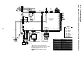
2-1-8. High Wall Type
PMV
1 1
Model: MMK-AP0071H, AP0091H, AP0121H, AP0151H, AP0181H, AP0241H
FM
5 5
4 4
BLK
RED
5 4 3 2 1
S
HBS
CN22
1 2 3 4 5
6 5 4 3 2 1
6 5 4 3 2 1
6 5 4 3
6 5 4 3
1
1
CN82
(BLU)
6 5 4 3 2
6 5 4 3 2 1
CN33
(WHI)
CN210
(WHI)
CN44 CN40
(BRW) (BLU)
DC 15V
1 2 3 4 5
1 2 3 4 5
1 2 3 4 5
Flow selector unit
(Sold separately)
Power
supply
circuit
CN213 (WHI)
Infrared rays receive
and indication parts
(MCC-861)
(MCC-1510)
Control P.C.board for indoor unit
(BRW)
CN101
(BLU)
BLK
1 1
2 2 BLK
Heat
exchanger
sensor
(TC2)
CN103
(GRN)
1
2
CN102
(YEL)
BLK
1 1
BLK
2 2
Heat
exchanger
sensor
(TCJ)
BLK
1 1
BLK
2 2
Thermo
sensor
(TA)
CN104
CN80 (WHI)
(GRN)
CN61
(YEL)
CN60
(WHI)
1 2
1 2 3 4 5 6
1 2 3 4 5 6
1 2 3 4 5 6
1 2 3
Option
PNL/EMG
1 2 3 4
HA
BLK
3 3
2
WHI
1 1
Heat
exchanger
sensor
(TC1)
CN32
(WHI)
Fan drive
BLU
1 1
2 2 BLU
BLK
1 1
2
BLK
3 3
DC 7V
1 2 3 4 5 6 7 8 9 10
1 2 3 4
7 8 9 10
9
7 6 5 4 3 2
11 10 9 8 7 6 5 4 3 2 1
CN41
(BLU)
DC 0V
CN100
DC 12V
GRY
ORN
RED
BLU
3
3
WHI
BRW
YEL
GRY
PNK
RED
CN309 1
(YEL) 1
GRN & YEL
WHI
CN81 (BLK)
WHI
BRW
YEL
5
CN67
(BLK)
GRN & YEL
26
GRN & YEL
Outdoor unit
1 2
F301 Fuse
T3. 15A 250V~
1 1
WHI 3 3
Power Supply
Single phase
220-240V 50Hz
220V 60Hz
indicates the terminal block, letter at inside
indicates the terminal number.
2. A dotted line and broken line indicate the
wiring at site.
3.
indicates the control P.C. board.
F
CN50
(WHI)
Heat exchanger
1.
Fan
motor
YEL
YEL
YEL
YEL
WHI
:
Louver
motor
Pulse motor
valve
RED
GRN
BROWN
RED
WHITE
YELLOW
BLUE
BLACK
GRAY
PINK
ORANGE
GREEN &
YELLOW
GREEN
BLU
YEL
WHI
BLK
:
:
:
:
:
:
:
:
:
:
RED
BRW
BLU
ORN
YEL
WHI
BRW
RED
WHI
YEL
BLU
BLK
GRY
PNK
ORN
GRN & YEL
TF
1 2
1 2
CN1(WHI)
Wierd remote
controller
(Sold separately)
Model: MMK-AP0072H, AP0092H, AP0122H
Color identification
RC
6 4 3 1 2 5
6 4 3 1 2 5
RED BLK ORN BLU YEL
FAN
7
5
3
1
CN083 9
(WHI) 9
7
5
3
1
H
M
L
CN068
(BLU) 1
DP
3
LM
1
PMV
1 2 3 4 5 6 CN082
1 2 3 4 5 6 (BLU)
CN033
3 (GRN)
UL
RY007
P301
(BLK)
RY002
RY004
(GRY)
CN304
3 3
RY005
1 1
AC IN
RED
Control P.C. board
for Indoor unit
MCC-1403
(YEL)
CN309
3 3
1 1
1 1
2 2
CN102
(RED)
1 1
2 2
CN101
(BLK)
1 1
2 2
CN100
(BRN)
1 1
2 2
CN080
(GRN)
1
2 PNL
3
CN073
(RED)
1
EXCT
2
CN070
(WHI)
1
2
CN081
(BLK)
1
2
3
4
5
FUSE
27
CN066
(WHI)
1 1
2 2
Power supply
circuit
CN050
(WHI)
1 2 3 RC
1
3
TR
Network adapter
(Option)
3 3
2
1 1
CN032
(WHI)
CN060
(WHI)
3
3
1 2 3 4 5 6
1 2 3 4 5 6
1 2 3 4 5 6
T10
1 2
1 2 3 4 5 6
Fan
drive
Option
1 2 3 4 5 6
1 2 3 4 5 6
CN02
(YEL)
Sub P.C. board
MCC-1520
CN01(WHI)
Flow selector
unit earth
screw
Line filter
CN02
(BLU)
1 2 3 4 5 6
1 2 3 4 5 6
CN01
(WHI)
CN03(RED)
U1 U2
A
B
X Y
U1 U2
Outdoor unit
1 2
1 2
CN1
TR
1 2
1 2
R(L) S(N)
Power supply
single phase
220-240V 50Hz
220V 60Hz
CN074 1
(WHI) 1
1 2 3 4 5
1 2
1 2
CN061
(YEL)
CN075
(WHI)
BLK
BLU
BLU
1 2
1 2
CN041
(BLU)
BLK
CN040
(BLU)
Indoor unit
earth screw
TCJ
TC2
TC1
T5.0A 250V~
3 3
WHI
CN067
(BLK)
RED
Closed-end
connector
WHI
TA
CN104
(YEL)
RY001
RY006
1 1
FS
1
3 CN030
1 2 3 (RED)
MCC-1401
1.
Remote controller
indicates the terminal block.
Letter at inside indicates the terminal number.
2. A dotted line and broken line indicate
the wiring at side.
3.
indicates the control P.C. board.
Symbol
FM
RC
TR
TA
TC1,TC2,TCJ
RY001
RY002
RY004
RY005~007
PMV
Filter
Color
indication
RED : RED
WHI : WHITE
YEL : YELLOW
BLU : BLUE
BLK : BLACK
GRY : GRAY
PNK : PINK
ORN : ORANGE
BRW : BROWN
GRN : GREEN
Parts name
Fan motor
Running capacitor
Transformer
Indoor temp sensor
Temp sensor
Louver control relay
Drain control relay
Heater control relay
Fan motor control relay
Pulse motor valve
2-1-9. Floor Standing Cabinet Type
FM
PMV
2
3
4
5
6
Model: MML-AP0071H, AP0091H, AP0121H, AP0151H, AP0181H, AP0241H
2
3
4
5
6
WHI
RED
RC
2
4
5
6
3
FM
WHI
GRN
RED
PMV
2
4
5
6
3
6 4 3 1 2 5
6 4 3 1 2 5
RC
RED BLK ORN BLU YEL
FAN
7
5
3
1
CN083 9
(WHI) 9
7
5
3
1
RED BLK ORN BLU YEL
FAN
7
5
3
1 CN068 1
CN083 9
(WHI) 9
(BLU) 1
7
5
3
1
H
For AP0071BH,AP0091BH,AP0121BH
M
L
3
3
1
1
3 CN033
3 (GRN)
1
3
1 2 3
CN030
(RED)
UL
RY007
R301
(BLK)
RY002
RY004
RY006
1
3
(GRY)
CN304
RY005
1 1
3 3
AC IN
1 1
RY001
Control P.C. board
for undoor unit
MCC-1403
(YEL)
CN309
FUSE
3 3
1
2
1
2
1 2 3 4 5 6
1 2 3 4 5 6 PMV
1 1
2 2
CN102
(RED)
1 1
2 2
CN101
(BLK)
1 1
2 2
CN100
(BRW)
1 1
2
3 3
CN080
(GRN)
1
2 PNL
3
CN073
(RED)
1
EXCT
2
CN070
(WHI)
1
2
CN081
(BLK)
1
2
3
4
5
T5.0A 250V~
(BLK)
CN067
CN066
(WHI)
CN044
(BRW)
EMG
28
CN082
(BLU) CN104
(YEL)
Power supply
circuit
CN040
(BLU)
CN041
(BLU)
CN050
(WHI)
1 2
1 2
1 2 3
1
3
1 2 3 4 5
CN075
(WHI)
CN074 1
(WHI) 1
3
3
1 2 3 4 5 6
1 2 3 4 5 6
CN061
(YEL)
1 2 3 4 5 6
CN032
(WHI)
CN060
(WHI)
1 2
1 2 3 4 5 6
Fan
drive
Option
Sub P.C. board
MCC-1520
WHI
RED
1 2 3 4 5 6 CN01
1 2 3 4 5 6 (WHI)
1 2
1 2
TR
Network
adaptor
(Option)
TR
CN01(WHI)
Flow selector
unit earth
screw
RED
U1 U2
R(L) S(N)
Power supply
single phase
220-240V 50Hz
220V 60Hz
B
X
Y
3 3
2
1 1
CN02
(BLU)
1 1
2 2
CN03
(RED)
CN03(RED)
Closed-end
connector
MCC-1401
WHI
Indoor unit
earth screw
A
U1 U2
1 2
1 2
Outdoor unit
CN1
Remote controller
1.
indicates the terminal block.
Letter at inside indicates the terminal number.
2. A dotted line and broken line indicate the wiring at side.
3.
indicates the control P.C. board.
Color
indication
RED : RED
WHI : WHITE
YEL : YELLOW
BLU : BLUE
BLK : BLACK
GRY : GRAY
PNK : PINK
ORN : ORANGE
BRW : BROWN
GRN : GREEN
Symbol
FM
RC
TR
TA
TC1,TC2,TCJ
RY001
RY002
RY004
RY005~007
PMV
TCJ
TC2
Filter
1 2 3 4 5 6 CN02
1 2 3 4 5 6 (YEL)
1 2
1 2
TA
Parts name
Fan motor
Running capacitor
Transformer
Indoor temp sensor
Temp sensor
Louver control relay
Drain control relay
Heater control reley
Fan motor control relay
Pulse motor valve
TC1
2-1-10. Floor Standing Concealed Type
FM
1
3
2
4
5
6
Model: MML-AP0071BH, AP0091BH, AP0121BH, AP0151BH, AP0181BH, AP0241BH
GRN
1
3
2
4
5
6
FM
BRW
3
4
5
6
7
PMV
LM
2 1
2 1
M
H
L
6 4 3 1 2 5
6 4 3 1 2 5
LM
RED BLK ORN BLU YEL
FAN
7
5
3
1
CN083 9
(WHI) 9
7
5
3
1
CN068
(BLU) 1
DP
1
1
3
3 CN033
3 (GRN)
PMV
1 2 3 4 5 6 CN082
1 2 3 4 5 6 (BLU)
1
3 CN030
1 2 3 (RED)
UL
RY007
P301
(BLK)
RY002
RY004
RY001
RY006
1
(GRY)
CN304
3
RY005
1 1
FUSE
CN066
(WHI)
1
2
CN044
(BRW)
1
2
Power supply
circuit
CN050
(WHI)
1 2 3 RC
1
3
CN075
(WHI)
CN074 1
(WHI) 1
1 2 3 4 5
BLK
BLU
1 2
1 2
CN041
(BLU)
BLK
CN040
(BLU)
BLU
WHI
29
RED
(BLK)
CN067
EMG
1 2
1 2
TR
Indoor unit
earth screw
CN102
(RED)
1 1
2 2
CN101
(BLK)
1 1
2 2
Network adaptor
(Option)
3 3
2
1 1
Line filter
1 2 3 4 5 6
1 2 3 4 5 6
1 2 3 4 5 6
CN02
(BLU)
TCJ
TC2
1 1
TC1
3 3
1
2 PNL
3
CN073
(RED)
1
EXCT
2
CN070
(WHI)
1
Filter
2
CN081
(BLK)
1
2
3
4
5
CN032
(WHI)
CN060
(WHI)
1 2
1 2 3 4 5 6
Fan
drive
Option
1 2 3 4 5 6 CN02
(YEL)
1 2 3 4 5 6
Sub P.C. board
MCC-1520
CN01(WHI)
1 2
1 2
3
3
CN061
(YEL)
TA
CN080
(GRN)
T5.0A 250V~
3 3
Flow selector
unit earth
screw
1 1
2 2
CN100
(BRW)
Control P.C. board
for Indoor unit
MCC-1403
(YEL)
CN309
3 3
AC IN
1 1
CN104
(YEL)
1 2 3 4 5 6 CN01
1 2 3 4 5 6 (WHI)
Color
indication
RED : RED
WHI : WHITE
YEL : YELLOW
BLU : BLUE
BLK : BLACK
GRY : GRAY
PNK : PINK
ORN : ORANGE
BRW : BROWN
GRN : GREEN
CN03(RED)
Closed-end
connector
U1 U2
A
B
Power supply
single phase
220-240V 50Hz
220V 60Hz
X Y
U1 U2
Outdoor unit
1 2
1 2
CN1
TR
1 2
1 2
R(L) S(N)
MCC-1401
Remote controller
1.
indicates the terminal block, letter.
Letter at inside indicates the terminal number.
2. A dotted line and broken line indicate
the wiring at side.
3.
indicates the control P.C. board.
Symbol
FM
RC
TR
LM
TA
TC1,TC2,TCJ
RY001
RY002
RY005~007
PMV
Parts name
Fan motor
Running capacitor
Transformer
Louver motor
Indoor temp sensor
Temp sensor
Louver control relay
Drain control relay
Fan motor control relay
Pulse motor valve
2-1-11. Floor Standing Type
RC
3
4
5
6
7
8
Model: MMF-AP0151H, AP0181H, AP0241H, AP0271H, AP0361H, AP0481H, AP0561H
1 1
1
3
: RED
: WHITE
: YELLOW
: BLUE
: BLACK
: GRAY
: PINK
: ORANGE
: BRWN
: GREEN
5 4
1 CN334
5 4 3 2 1 (WHI)
1
1
3
3
5 CN333
5 (WHI)
1
3
1 2 3
(External static pressure setup)
1 2 3 4 5 6 CN82
1 2 3 4 5 6 (BLU)
Drain pump type
("SPH" Type)
CN68
(BLU)
1 1
CN34
(RED)
CN33
1 2
1 2
1 2
1 2
CN112
(WHI)
CN111
(WHI)
CN110
(WHI)
1 2 3 4 5 (WHI)
CN71
(CHK)
CN72
(DISP)
FS
1
3
1 2 3
RY302
DM
3 3
Motor drive
circuit
1
CN304
(GRY)
3
RED
WHI
Fuse
T3.15A
250V~
Fuse
T6.3A
250V~
1 1
Power
supply
circuit
3 3
30
CN67
(BLK)
P301
BLK
1
2
Flow
Selector unit
Indoor unit
R(L) S(N)
Earth screw
Earth screw
Power supply
220-240V~, 50Hz
220V~, 60Hz
CN309
(YEL)
1 2
1 2
1 2 3
1
3
1
3
1.
U1 U2
U1 U2
A
A
B
Outdoor unit
Wired remote
controller
CN102
(RED)
1 1
2 2
CN101
(BLK)
1 1
2 2
TC2
1 1
3 3
CN73
(RED)
1
EXCT
2
CN70
(WHI)
1
2
CN60
(WHI)
CN81
(BLK)
CN20
(BLU)
1 2 3 4 5
1 2 3 4 5 6
1 2
Fan drive
1 2 3 4 5 6
Option
1 2 3 4 5
1 2 3 4 5
Parts name
Fan motor
Indoor temp sensor
Temp sensor
Drain control relay
Pulse motor valve
Drain pump motor
Float switch
TCJ
1
2 PNL
3
CN32
(WHI)
Symbol
FM
TA
TC1,TC2,TCJ
RY302
PMV
DM
FS
TA
CN80
(GRN)
CN61
(YEL)
indicates the terminal bolock.
Letter at inside indicates the terminal number.
2. A dotted line and broken line indicate the
wiring at side
3.
indicate a control P.C. board.
B
1 1
2 2
CN50
(WHI)
BLK
CN41
(BLU)
BLU
RED
CN40
(BLU)
BLU
BLK
WHI
Closed-end
connector
CN66
(WHI)
CN44 1
(BRW) 2
CN104
(YEL)
CN100
(BRW)
Control P.C. board
for undoor unit
MCC-1402
DC20V
DC15V
DC12V
DC7V
CN34
(RED)
TC1
2-1-12. Slim Duct Type
6 4 3 1 2 5
6 4 3 1 2 5
Model: MMD-AP0071SPH, AP0091SPH, AP0121SPH, AP0151SPH, AP0181SPH
RED
WHI
YEL
BLU
BLK
GRY
PNK
ORN
BRN
GRN
Drain pump type
("SPH" Type)
FM
CN68
(BLU)
Color
indication
Non Drain pump type
("SH" Type)
PMV
Non Drain pump type
("SH" Type)
2-2. Outdoor Unit
31
Model: MCY-MAP0401HT, MCY-MAP0501HT, MCY-MAP0601HT,
MCY-MAP0401HT2D, MCY-MAP0501HT2D, MCY-MAP0601HT2D
Capacitor
2-3. Connection of PMV Kit
Model: RBM-PMV0361E, RBM-PMV0901E
Indoor unit
Pulse motor valve (PMV)
(Indoor unit side)
PMV lead wires
PMV Kit
Connection cable
PMV
CN82 connector
Connector conversion cable
32
Indoor control P.C. board
3. PARTS RATING
3-1. Indoor Unit
4-way Air Discharge Cassette Type
Model
MMU-AP
0091H
0121H
0151H
Fan motor
0181H
0241H
0271H
SWF-230-60-1
Drain pump motor
ADP-1409
Float switch
FS-0218-102
TA sensor
Lead wire length : 155mm
TC1 sensor
Ø4 size lead wire length : 1200mm Vinyl tube (Blue)
TC2 sensor
Ø6 size lead wire length : 1200mm Vinyl tube (Black)
TCJ sensor
Ø6 size lead wire length : 1200mm Vinyl tube (Red)
Pulse motor
EDM-MD12TF-3
Pulse motor valve
EDM-B25YGTF
EDM-B40YGTF
Louver motor (panel)
Model
0301H
MP24GA
MMU-AP
0361H
0481H
Fan motor
SWF-200-90-1
Drain pump motor
ADP-1409
Float switch
FS-0218-102
TA sensor
Lead wire length : 155mm
TC1 sensor
Ø4 size lead wire length : 1200mm Vinyl tube (Blue)
TC2 sensor
Ø6 size lead wire length : 1200mm Vinyl tube (Black)
TCJ sensor
Ø6 size lead wire length : 1200mm Vinyl tube (Red)
Pulse motor
EDM-MD12TF-3
Pulse motor valve
EDM-B60YGTF-1
Louver motor (panel)
MP24GA
Compact 4-way Air Discharge Cassette Type
Model
MMU-AP
0071MH
0091MH
Fan motor
0121MH
0151MH
SWF-230-60-1
Drain pump motor
ADP-1409
Float switch
FS-0218-102
TA sensor
Lead wire length : 155mm
TC1 sensor
Ø4 size lead wire length : 1200mm Vinyl tube (Blue)
TC2 sensor
Ø6 size lead wire length : 1200mm Vinyl tube (Black)
TCJ sensor
Ø6 size lead wire length : 1200mm Vinyl tube (Red)
Pulse motor
EDM-MD12TF-3
Pulse motor valve
EDM-B25YGTF
EDM-B40YGTF
Louver motor (panel)
MP24GA
33
0181MH
2-way Air Discharge Cassette Type
Model
MMU-AP
0071WH
Fan motor
0091WH
0121WH
0151WH
AF-230-53-4G
Running capacitor for fan motor
AC 400V, 1.0µF
AC 450V, 2.0µF
Drain pump motor
PJD-05230TF-1
Float switch
FS-0208-608
Control P.C. board transformer
TT-13
Pulse motor
EDM-MD12TF-3
Pulse motor valve
EDM-B25YGTF
TA sensor
EDM-B40YGTF
Lead wire length : 268mm
TC1 sensor
Ø4 size lead wire length : 1200mm Vinyl tube (Blue)
TC2 sensor
Ø6 size lead wire length : 1200mm Vinyl tube (Black)
TCJ sensor
Ø6 size lead wire length : 1200mm Vinyl tube (Red)
Model
0181WH
AF-230-39-4B
MMU-AP
0241WH
0271WH
Fan motor
0301WH
AF-200-53-4F
Running capacitor for fan motor
AC 450V, 2.5µF
Drain pump motor
AC 450V, 3.5µF
PJD-05230TF-1
Float switch
FS-0208-608
Control P.C. board transformer
TT-13
Pulse motor
EDM-MD12TF-3
Pulse motor valve
EDM-B40YGTF
TA sensor
Lead wire length : 268mm
TC1 sensor
Ø4 size lead wire length : 1200mm Vinyl tube (Blue)
TC2 sensor
Ø6 size lead wire length : 1200mm Vinyl tube (Black)
TCJ sensor
Ø6 size lead wire length : 1200mm Vinyl tube (Red)
1-way Air Discharge Cassette (Compact type) Type
Model
MMU-AP
0071YH
0091YH
Fan motor
Running capacitor for fan motor
AC 400V, 1µF
Drain pump motor
PJD-05230TF-1
Float switch
FS-0208-602
Control P.C. board transformer
TT-13
Pulse motor
EDM-MD12TF-3
Pulse motor valve
EDM-B25YGTF
TA sensor
Lead wire length : 818mm
TC1 sensor
Ø4 size lead wire length : 1200mm Vinyl tube (Blue)
TCJ sensor
Ø6 size lead wire length : 1200mm Vinyl tube (Red)
Model
MMU-AP
0152SH
0182SH
Fan motor
SWF-280-60-1
Running capacitor for fan motor
—
Drain pump motor
ADP-1409
Float switch
FS-0218-103
Control P.C. board transformer
—
Pulse motor
EDM-MD12TF-3
Pulse motor valve
TA sensor
0121YH
AF-200-22-4N-1
EDM-B40YGTF-3
Lead wire length : 155mm Vinyl tube
TC1 sensor
Ø4 size lead wire length : 1200mm Vinyl tube (Blue)
TC2 sensor
Ø6 size lead wire length : 1200mm Vinyl tube (Black)
TCJ sensor
Ø6 size lead wire length : 1200mm Vinyl tube (Red)
34
0242SH
Concealed Duct Standard Type
Model
MMD-AP
0071BH
0091BH
0121BH
Fan motor
0151BH
0181BH
ICF-280-120-2
Drain pump motor
ADP-1409
Float switch
FS-0218-102
Pulse motor
EDM-MD12TF-3
Pulse motor valve
EDM-B25YGTF
TA sensor
EDM-B40YGTF
Lead wire length : 618mm
TC1 sensor
Ø4 size lead wire length : 1200mm Vinyl tube (Blue)
TC2 sensor
Ø6 size lead wire length : 1200mm Vinyl tube (Black)
TCJ sensor
Ø6 size lead wire length : 1200mm Vinyl tube (Red)
Model
MMD-AP
0241BH
0271BH
Fan motor
0301BH
0361BH
ICF-280-120-1
0481BH
ICF-280-120-2
Drain pump motor
ADP-1409
Float switch
FS-0218-102
Pulse motor
EDM-MD12TF-3
Pulse motor valve
EDM-B40YGTF
TA sensor
EDM-B60YGTF-1
Lead wire length : 618mm
TC1 sensor
Ø4 size lead wire length : 1200mm Vinyl tube (Blue)
TC2 sensor
Ø6 size lead wire length : 1200mm Vinyl tube (Black)
TCJ sensor
Ø6 size lead wire length : 1200mm Vinyl tube (Red)
Concealed Duct High Static Pressure Type
Model
MMD-AP
Fan motor
Running capacitor for fan motor
0181H
0241H
0271H
0361H
0481H
STF-200-160-4B
STF-200-160-4A
STF-200-260-4C
STF-200-260-4B
AC 500V, 4µF
AC 400V, 8µF
AC 450V, 6µF
AC 400V, 8µF
Drain pump motor
ADP-1409
Float switch
FS-0218-102-6
Pulse motor
EDM-MD12TF-3
Pulse motor valve
EDM-B40YGTF
TA sensor
EDM-B60YGTF-1
Lead wire length : 1200mm
TC1 sensor
Ø4 size lead wire length : 1200mm Vinyl tube (Blue)
TC2 sensor
Ø6 size lead wire length : 1200mm Vinyl tube (Black)
TCJ sensor
Ø6 size lead wire length : 1200mm Vinyl tube (Red)
Slim Duct Type
Model
MMD-AP
0071SPH(SH)
0091SPH(SH)
0121SPH(SH)
Fan motor
EDM-MD12TF-3
EDM-B25YGTF
EDM-B40YGTF
Drain pump motor ∗
ADP-1409
Float switch ∗
TA sensor
FS-0218-102
Lead wire length : 1558mm
TC1 sensor
Ø4 size lead wire length : 1200mm Vinyl tube (Blue)
TC2 sensor
Ø6 size lead wire length : 1200mm Vinyl tube (Black)
TCJ sensor
Ø6 size lead wire length : 1200mm Vinyl tube (Red)
∗
0181SPH(SH)
SWF-280-60-1
Pulse motor
Pulse motor valve
0151SPH(SH)
“SPH” series only.
35
Under Ceiling Type
Model
MMC-AP
Fan motor
Louver motor
Pulse motor
Pulse motor valve
TA sensor
TC1 sensor
TC2 sensor
TCJ sensor
0151H
0181H
SWF-280-60-1
0241H
0271H
SWF-280-60-2
MP24GA1
EDM-MD12TF-3
0361H
0481H
SWF-280-120-2
EDM-B40YGTF
EDM-B60YGTF-1
Lead wire length : 155mm Vinyl tube
Ø4 size lead wire length : 1200mm Vinyl tube (Blue)
Ø6 size lead wire length : 1200mm Vinyl tube (Black)
Ø6 size lead wire length : 1200mm Vinyl tube (Red)
High Wall Type
Model
MMK-AP
Fan motor
Louver motor
Pulse motor
Pulse motor valve
TA sensor
TC1 sensor
TC2 sensor
TCJ sensor
0071H
0091H
0121H
0151H
ICF-280-120-3
MT8-3-6
0181H
0241H
0072H
0092H
0122H
ICF-340-30 or MF-340-30
MP24Z
EDM-MD12TF-3
EDM-B25YGTF
EDM-B40YGTF
EDM-B25YGTF-3
Lead wire length : 818mm Vinyl tube
Lead wire length : 318mm Vinyl tube
Ø4 size lead wire length : 1200mm Vinyl tube (Blue)
Ø4 size lead wire length : 600mm Vinyl tube (Blue)
Ø6 size lead wire length : 1200mm Vinyl tube (Black)
Ø6 size lead wire length : 800mm Vinyl tube (Black)
Ø6 size lead wire length : 1200mm Vinyl tube (Red)
Ø6 size lead wire length : 800mm Vinyl tube (Red)
Floor Standing Cabinet Type
Model
MML-AP
Fan motor
Running capacitor for fan motor
Transformer
Pulse motor
Pulse motor valve
TA sensor
TC1 sensor
0071H
0091H
AF-200-19-4F
AC450V, 1.2µF
0121H
0151H
0181H
0241H
AF-200-45-4F
AF200-70-4K
AC400V, 1.8µF
AC450V, 2µF
TT13
EDM-MD12TF-3
EDM-B25YGTF
EDM-B40YGTF
Lead wire length : 818mm Vinyl tube
Ø4 size lead wire length : 1200mm Vinyl tube (Blue)
TC2 sensor
TCJ sensor
Ø6 size lead wire length : 1200mm Vinyl tube (Black)
Ø6 size lead wire length : 1200mm Vinyl tube (Red)
Floor Standing Concealed Type
Model
MML-AP
Fan motor
Running capacitor for fan motor
Transformer
Pulse motor
Pulse motor valve
TA sensor
TC1 sensor
TC2 sensor
TCJ sensor
0071BH
0091BH
AF-200-19-4G
AC450V, 1.5µF
0121BH
0151BH
0181BH
AF-200-70-4K
AC450V, 1µF
0241BH
AC450V, 2µF
TT-13
EDM-MD12TF-3
EDM-B25YGTF
EDM-B40YGTF
Lead wire length : 818mm Vinyl tube
Ø4 size lead wire length : 2000mm Vinyl tube (Blue)
Ø6 size lead wire length : 2000mm Vinyl tube (Black)
Ø6 size lead wire length : 2000mm Vinyl tube (Red)
Floor Standing Type
Model
MMF-AP
Fan motor
Running capacitor for fan motor
Transformer
Pulse motor
Pulse motor valve
Louver motor
TA sensor
TC1 sensor
TC2 sensor
TCJ sensor
0151H
0181H
AF-200-37R
AC500V, 3µF
0241H
0271H
0361H
0481H
AF-200-110M-1
AF-200-63T
AF-200-160H-1
AC500V, 3.5µF
AC500V, 4µF
TT-13
EDM-MD12TF-3
EDM-B40YGTF
EDM-B60YGTF-1
MT8-3-9
Lead wire length : 1200mm Vinyl tube
Ø4 size lead wire length : 1200mm Vinyl tube (Blue)
Ø6 size lead wire length : 2000mm Vinyl tube (Black)
Ø6 size lead wire length : 1200mm Vinyl tube (Red)
36
3-2. Outdoor Unit
Model
MCY-MAP0401HT
MCY-MAP0501HT
Compressor
MCY-MAP0601HT
DA421A3F-20M2
4-way valve coil
VHV type (AC220–240V, 50Hz)
4-way valve
STF-0401G1
Pulse motor valve coil
HAM-MD12TF-3 (DC12V)
Pulse motor valve
HAM-BD24TF-1
Solenoid valve coil
SV2, SV4, SV5 : VPV type (AC220-240V, 50Hz)
Solenoid valve
High-pressure SW
SV2 : VPV122DQ1, SV4, SV5 : VPV303DQ1
ACB-4UB32W (Open : 3.73MPa, Close : 2.9MPa)
High-pressure sensor
NSK-BC038F-067 (0.5 to 4.3V / 0 to 3.73MPa)
Low-pressure sensor
NSK-BC010F-067 (0.5 to 3.5V / 0 to 0.98MPa)
Fan motor
ICF-140-63-2R (DC)
Case heater
Compressor (AC240V, 29W), Accumulator (AC240V, 24W)
Compressor case thermo.
Model
US-622KXTMQO-SS (OFF : 125°C, ON : 90°C)
MCY-MAP0401HT2D
MCY-MAP0501HT2D
Compressor
MCY-MAP0601HT2D
DA421A3F-20M2
4-way valve coil
VHV type (AC220V, 60Hz)
4-way valve
STF-0401G1
Pulse motor valve coil
HAM-MD12TF-3 (DC12V)
Pulse motor valve
HAM-BD24TF-1
Solenoid valve coil
SV2, SV4, SV5 : VPV type (AC220V, 60Hz)
Solenoid valve
High-pressure SW
SV2 : VPV122DQ1, SV4, SV5 : VPV303DQ1
ACB-4UB32W (Open : 3.73MPa, Close : 2.9MPa)
High-pressure sensor
NSK-BC038F-067 (0.5 to 4.3V / 0 to 3.73MPa)
Low-pressure sensor
NSK-BC010F-067 (0.5 to 3.5V / 0 to 0.98MPa)
Fan motor
ICF-140-63-2R (DC)
Case heater
Compressor (AC240V, 29W), Accumulator (AC240V, 24W)
Compressor case thermo.
US-622KXTMQO-SS (OFF : 125°C, ON : 90°C)
3-3. PMV Kit
Model
RBM-PMV0361E
Pulse motor valve coil
RBM-PMV0901E
EDM-MD12TF-3 (DC12V)
37
3-5. Parts Layout in Outdoor Unit
Reactor box (Weight : 9kg)
I/F P.C.board
TL sensor
PMV(Pulse Motor valve)
TS sensor
Low pressure sensor
Solenoid valve (SV5)
Liquid tank
4-way valve
Solenoid valve (SV2)
High pressure sensor
Solenoid valve (SV4)
TD sensor
High pressure switch
Compressor
Compressor- case heater
TO sensor
Accumulator
Accumulator heater
TE sensor
38
3-6. Name of Each Part
[1-way Air Discharge Cassette Type]
MMU-AP0071YH to AP0121YH
Sold Separately Parts
Air outlet (Discharge)
Air outlet/Air outlet flap
It is included in the
electric parts box.
Select air blow direction incooling
or heating operation each.
Weekly timer
RBC-EXW21E2
Hot air is discharged when cooling operation is performed.
Cold air is discharged when heating operation is performed.
Earth screw
They are provided at front,
rear, left, and right sides.
Power source hole
Refrigerant pipe
connecting hole
Fixing leg
Wired remote controller
RBC-AMT31E
Air inlet
CODE No.
SET DATA SETTING TEST
UNIT No.
R.C.
H
No.
TEMP.
FILTER
RESET TEST
ON / OFF
TIMER SET
FAN
MODE
TIME
SWING/FIX
VENT
SET
CL
UNIT
Air filter
Air in the room is sucked from here.
Removes dust and trash.
(Air filter is provided in the air inlet grille.)
Button
Air outlet/Air outlet flap
Button to open/close
suction port
Change the direction of the air to be
discharged according to cool/heat mode.
[4-way Air Discharge Cassette Type]
MMU-AP0091H, AP0121H, AP0151H, AP0181H, AP0241H,
MMU-AP0271H, AP0301H, AP0361H, AP0481H, AP0561H
2-way discharge/3-way discharge
Air filter
Select air blow direction in cooling or
heating operation each.
2-way discharge or 3-way discharge can be
selected according to the shape or
arrangement of the room.
For details, consult with the dealer which you
have purchased the air conditioner.
Removes dust or trash.
(Provided on the suction port.)
It is included in the electric
parts box.
39
Air filter
Removes dust and trash.
(Air filter is provided in the air grille.)
Clip
The clip is to open/close the
air inlet grille.
Air inlet grille
Air in the room is sucked from here.
Simple wired remote controller
RBC-AS21E2
Air outlet/Air outlet flap
Earth screw
Suction port
Sucks air inside of the room from here.
TEST
Earth screw
˚C
It is included in the electric parts box.
SETTING
Air filter
Removes dust or trash.
(Provided on the suction port.)
[Concealed Duct Standard Type]
Air outlet flange
Earth screw
Discharge duct is
connected.
Earth screws are provided
in the electric parts box.
MMU-AP0071MH, AP0091MH, AP0121MH, AP0151MH, AP0181MH
Air outlet/Air outlet flap
It is included in the electric
parts box.
Air filter
Select air blow direction in cooling or
heating operation each.
Removes dust and trash.
(Air filter is provided in the air inlet grille.)
Removes dust and trash.
(Air filter is provided in the air grille.)
Clip
The clip is to open/close the
air inlet grille.
Air inlet grille
Air in the room is sucked from here.
[2-way Air Discharge Cassette Type]
Earth screw
Air outlet/Air outlet flap
It is included in the electric parts box.
Select air blow direction in cooling or
heating operation each.
Center panel
Air inlet
Air filter
Air in the room is
sucked from here.
Removes dust and trash.
(Air filter is provided in the center panel.)
Wireless remote controller kit
TCB-AX21E2
RBC-AX22CE2 RBC-AX21U(W)-E2
Earth screw
Air filter
SuMoTuWeTh Fr Sa
PROGRAM1
ERROR
PROGRAM2
PROGRAM3
WEEKLY TIMER
MMU-AP0152SH, AP0182SH, AP0242SH
Connecting valve is
included inside here.
3-6-2. Indoor Unit
Air inlet grille
Air inlet
Air in the room is sucked from here.
[Concealed Duct High Static Pressure Type]
Air outlet
Air inlet
Discharge duct is connected.
Suction duct is connected.
Drain pan
Earth screw
Earth screws are provided
in the electric parts box.
[Slim Duct Type]
Air inlet
Suction duct is connected.
Air filter
(Air filter is not provided to
some models in the series.)
39
Earth screw
It is included in the electric
parts box.
Air outlet
Discharge duct is
connected.
Central remote controller
TCB-SC642TLE2
3-6-1. Outdoor Unit
ZONE
ALL
ZONE
GROUP
CODE
No.
1234
SET DATA
SETTING
R.C.
UNIT No.
TEST
No.
GROUP
SELECT
ZONE
CL
SET
3-7. Parts Name of Remote Controller
[Under Ceiling Type]
Button
Air inlet port
Button to open/close the suction port
The air in the room is sucked in from this
port.
Display section
In the display example, all indicators are displayed for the explanation.
In reality only, the selected contents are displayed.
• When turning on the leak breaker for the first time, [SET DATA] flashes on
the display part of the remote controller. While this display is flashing, the
model is being automatically confirmed. After the [SET DATA] display has
disappeared, you may use the remote controller.
Earth screw
Air filter
Removes dust or trash.
(Provided on the suction port.)
[High Wall Type]
MMK-AP0071H to AP0241H
Air inlet grille
Air in the room is sucked from here.
Air filter
Removes dust and trash.
(Air filter is provided in the air inlet grille.)
Earth screws are provided in the electric
parts box.
Air outlet/Air outlet flap
Change the direction of the air to be discharged according to cool/heat mode.
Earth screw
2
3
4
5
6
15
Air outlet/Air outlet flap
1
Change the direction of the air to be
discharged according to cool/heat mode.
Air inlet grille
Air outlet/Air outlet flap
Change the direction of the air to be
discharged according to cool/heat mode.
Air filter
Removes dust and trash.
(Air filter is provided in the air inlet grille.)
Earth screw
Earth screws are provided in the electric
parts box.
[Floor Standing Cabinet Type]
1
Air outlet/Air outlet flap
2
40
3
It is prepared in the electric parts box.
4
Air inlet port
H
SET DATA display
Air outlet port
5
Earth screw
This accessory is installed at the local site.
Air inlet port
Sucks air inside of the room from here.
6
Air filter
Vertical flap
Exchanges the air direction according
to cooling or heating time.
The air can be automatically discharged
rightward/leftward at stated periods.
7
8
9
Air inlet port
Sucks air inside of the room from here.
VENT
Operation
section
UNIT
14
Flap position display
(for 4-Way Air Discharge Cassette Type
and Under Ceiling Type model only)
SWING display
Set up temperature display
The selected set up temp. is displayed.
11
Fixing metal holder (Right and left)
Remote controller sensor display
Displayed while the sensor on the remote
controller is used.
It is prepared in the electric parts box.
40
16
11
13
12 14
PRE-HEAT display
(for Heat-pump model only)
Operation ready display
No function display
Displayed if there is no function even when the
button is pushed.
15
Air volume select display
The selected air volume mode is displayed.
(HIGH)
(AUTO)
(MED.)
(LOW)
In the Concealed Duct High Static Pressure type
models, [HIGH] only is displayed for the air speed.
” is displayed, clean the air filter.
TEST run display
10
Water accumulated in the drain pan is
drained from here through the drain pipe.
10
Displayed when cooling or heating operation is
impossible because the outdoor temperature goes
out of the operable range.
Filter display
Displayed during the up/down movement of the
flap.
Drain pan
Earth screw
13
Timer setting setup display
Displays flap position.
Removes dirt or dust.
SWING/FIX
CL
While this indication is displayed, the indoor fan
will stop or will go into LOW mode.
16
Displayed during a test run.
Horizontal flap/Air outlet port
MODE
TIME
SET
Displayed when the heating operation starts or a
defrost operation is carried out.
Timer time display
If “FILTER
Removes dirt or dust.
(It is included in the suction port.)
Fixing metal holder
Air filter
12
CHECK display
When pushing the Timer setting button, the
display on the timer is selected in order of
→
[OFF] repeat OFF timer →
[OFF]
→ No display.
[ON]
Drain pan (With drain filter)
[Floor Standing Type]
FAN
17
No.
Operation mode select display
Time on the timer is displayed.
(When a fault/error occurs, the check code is
displayed.)
Sucks air inside of the room from here.
Front panel (Lower side)
FILTER
RESET TEST
UNIT No.
R.C.
Displayed while the protective device works or
a fault/error occurs.
Air filter
It is prepared in the electric parts box.
ON / OFF
TIMER SET
CODE No.
The selected operation mode is displayed.
Earth screw
[Floor Standing Concealed Type]
No.
TEMP.
SET DATA SETTING TEST
Displayed during the setup of the timer.
Exchanges the air direction according to
cooling or heating time.
Removes dirt or dust.
(It is included in the suction port.)
Display
section
UNIT No.
R.C.
H
78 9
Earth screws are provided in the electric
parts box.
MMK-AP0072H to AP0122H
Air in the room is sucked from here.
CODE No.
SET DATA SETTING TEST
Mode select control display
Displayed when pushing the “Operation mode
” button while the operation mode is fixed
select
in heating or cooling mode by the system manager
of the air conditioner.
17
Central control display
Displayed when using the remote controller together
with a central control remote controller.
If the Remote controller is prohibited at the central
flashes when operating the
control side,
ON / OFF
MODE
,
,
/
buttons. The change
will not be accepted.
(The contents available to be set up on the remote
controller differ according to the central control
mode. For details, refer to Owner’s Manual of the
central control remote controller.)
3-8. Correct Usage
Operation section
Push each button to select a desired operation.
This remote controller can operate a maximum of 8 indoor units.
When you use the air conditioner for the first time or when you change the SET DATA value, follow the procedure shown below. For consequent uses the display on the remote controller can be turned on by pushing the
ON / OFF
button only.
• Before the unit can begin operation, it is firstly necessary to set the units operating parameters. After this
ON / OFF
button only.
has been completed the air conditioner can be used by pushing the
Preparation
1 7
Turn on the main power supply and/or the leakage breaker.
TEMP.
10
2
5
FILTER
RESET TEST
ON / OFF
TIMER SET
FAN
MODE
TIME
SWING/FIX
VENT
SET
CL
UNIT
• When the power supply is turned on, a partition line is shown on the display part of the remote controller.
Note) When the power supply is turned on, the remote controller will not accept any operational inputs until
approximately 1 minute has passed. This is not a failure of the unit.
8
REQUIREMENT
9
4
6
ON / OFF
• While using the air conditioner, only operate it with the
button. Do not turn it off with the main
power switch or the leakage breaker.
• Do not turn off the leakage breaker while the air conditioner is in use.
• Turn on the leakage breaker 12 hours or more before the air conditioner is to begin operation or if the
system has not been in use for long periods of time.
3
1
2
41
3
4
5
Air volume select button
Selects the desired air volume mode.
For the Concealed Duct High Static Pressure
type models this function is unavailable.
Timer set button
The TIMER SET button is used when the timer
is set up.
7
Filter reset button
” display.
FILTER
RESET TEST
9
1
2
Operation select button
Selects the desired operation mode.
10
3
Set up temperature button
Adjusts the room temperature.
Set the desired set temperature by pushing
or
buttons.
the
Air flow direction and Swing function
UNIT
:
If there are multiple indoor units that are controlled by a single remote controller, simply
select each unit in turn for which you wish to
adjust the air flow direction.
SWING/FIX
:
Set up the auto swing and the angle of the flap.
• This function is not provided on the Concealed
Duct Standard Type, High Static Pressure
Type, Floor standing Cabinet Type, Floor
Standing Concealed Type, or Slim Duct Type.
TIMER SET
FAN
MODE
TIME
SWING/FIX
VENT
SET
CL
3
1
2
UNIT
Cooling only model
button
When the button is pushed, the operation
starts. If the button is pressed again, the unit
operation will stop.
When the unit operation has stopped, the
operation lamp and all of the displays will
disappear.
VENT
Fan
button
VENT
The
button is used when a fan which is
sold on the market is connected.
is displayed on the remote controller
• If
when pushing the VENT button, a fan is not
connected.
ON / OFF
ON / OFF
4
Operation lamp
The light will be ON when the unit is in operation and OFF when the unit is not being used.
Note) The light will flash if a protective device
has been operated or if the timer function has
an error.
8
Check button
The CHECK button is used to check the units
operation. During normal operation, do not use
this button.
Resets (Erases) the “FILTER
6
TEMP.
ON / OFF
Push the
button.
The operation lamp goes on, and the operation will start.
DRY
COOL
FAN
MODE
Select an operation mode with the
button.
One push of the button, and the display
changes in the order shown on the right.
• “DRY mode” function is not provided on the
Concealed Duct High Static Pressure Type.
Heat-pump model
HEAT
DRY
COOL
FAN
(Dehumidity)
Select the air volume with the FAN button.
AUTO
HIGH
MED.
LOW
One push of the button, and the display
changes in the order shown on the right.
• When the air volume is set to “AUTO
”, the air volume will differ according to the room temperature.
” symbol will be displayed and the air volume will be LOW.
• In DRY mode, the “AUTO
• In heating operation, if the room temperature is not heated sufficiently with the air volume set at “LOW
” operation, select the “MED.
” or “HIGH
” operation.
OPTION :
• The temperature sensor for the indoor unit is located near to the air inlet opening and therefore will
differ slightly from the actual room temperature. This difference may be increased/decreased depending
on the type of room and its design. (Automatic air speed cannot be selected in FAN mode.)
• The Air Volume function is not provided on the “Concealed Duct High Static Pressure Type” instead the
” symbol is displayed.
air speed “HIGH
Remote controller sensor
In normal installations the temperature of the room
is sensed by a temperature sensor on the indoor
unit. However it is possible to have the sensor
within your remote controller. For further details
please contact your local dealer.
• In cases where one remote controller controls the
multiple indoor units, the setup operation is
unavailable in group control.
4
Determine the set up temperature by pushing the “TEMP.
Stop
Push the
ON / OFF
button.
The operation lamp goes off and the unit will stop.
41
” or “TEMP.
” button.
How to set up the air direction
REQUIREMENT
Push SWING/FIX button.
[In Cooling operation]
1
• The operation will start after approximately 1 minute.
[In Heating operation (For Heat-pump model only)]
Every pushing the button, the air direction changes.
In Heating operation
• In heating operation, the fan operation may continue for approximately 30 seconds after the air conditioner has stopped.
• The indoor fan will continue the preheat operation for 3 to 5 minutes under stop conditions. The indoor
unit will then begin to blow out hot air.
(
symbol on the remote controller display will come on.)
• When the temperature of the room has reached the setup temperature and the outdoor unit stops, the
air speed reduces and so the air volume will decrease.
mode, if the room temperature reaches the set temperature, the outdoor unit will stop and
• In HEAT
the air flow / volume will decrease.
is displayed.
• In the defrost mode, the fan will stop so that cool air is not discharged and the PRE-DEF
Set the air outlet flap downward.
If directing it upward, the hot air may not come to the foot.
Initial setup
In Cooling / Dry operation
Set the air outlet flap Upwards.
If directing it downwards, the dew may form on the near side of the air discharge
port and could drip.
How to adjust the the air flow direction,
using the swinging function
3-9. Adjustment of Wind Direction
2
To increase the cooling or heating effect, be sure to use the discharge flap in different directions when in cooling or heating operation.
The characteristics of air are such that cold air will accumulate in the lower half of the room, while hot air will
accumulate in the upper half.
42
CAUTION
Set the flap horizontally in cooling operation.
If a cooling operation is performed with a downwards discharge, the surface of the discharge port or flap
will become wet with dew, and water may drip down.
Push the SWING/FIX button.
Set the direction of the air outlet flap to
the lowest position and then push the
SWING/FIX
button again.
• [SWING
] is displayed and the air flow
direction will automatically change either
upwards/downwards.
In the case where one remote controller
controls multiple indoor units, each indoor unit
can be selected and its air flow direction can
be adjusted.
How to stop the flap from swinging
REQUIREMENT
3
• If a heating operation is performed with a horizontal discharge, unevenness the room temperature may
not be equal i.e. there may be a large variance between one side of the room with the other.
4-way Air Discharge Cassette Type
• When the air conditioner is not in operation, the discharge flap will automatically directs downwards.
• When the air conditioner is in ready status for heating,
the discharge flap will be directed upwards.
The swinging operation will begin after heating ready
status has been cleared. Please note the “SWING
”
symbol will still be displayed on the remote controller
even when the unit status is ready to begin the heating operation.
4
Push the SWING/FIX button again while the
horizontal flap is moving.
• The horizontal flap can be stopped at any
position desired. If you wish to return the flap
to it original upwards position, press the SWING/FIX
button again.
* During the cooling/drying operation the
horizontal flap will not stop at its most downwards facing position 9 (reduce the risk of
water dripping), but will instead move to the
3rd position from the top (as shown in the
figure).
Use the discharge flap with a horizontal set point.
[In Heating operation (For Heat-pump model only)]
Use the discharge flap with a downwards set point.
42
TEMP.
FILTER
RESET TEST
ON / OFF
TIMER SET
FAN
MODE
TIME
SWING/FIX
VENT
SET
CL
UNIT
1, 2, 3
4
In FAN operation
In all modes
Series of
operation
Initial setup
Display when stopping the swing
Fan/Heat
operation
Cool/Dry
operation
UNIT
• To set up the air flow direction individually,
UNIT
push the
button to display each indoor
unit No. in a group control. You can then set the
air flow direction for the displayed indoor unit.
• If there is no display, all the indoor units can be
operated collectively.
UNIT
button, the display
• For every push of the
will alter between units as shown in the figure.
[In Cooling operation]
Initial setup
No display
Unit No. 1-1
Unit No. 1-4
Unit No. 1-2
Unit No. 1-3
Based on the shape or arrangement of the room, the cold air and hot air can be discharged in two directions
or three directions. For details, please contact your local dealer.
Under Ceiling Type
• While the air conditioner is not in operation, the horizontal flap (Up/Down air direction adjustment plate) will automatically point upwards.
• When the air conditioner is in ready status for heating, the horizontal flap (Up/Down air direction adjustment plate) will points upwards. The swinging operation will begin after the heating
ready status has been cleared. Please note the “SWING
” symbol will still be displayed on
the remote controller even when the status is ready to heat.
INFORMATION
• If cooling operation is performed with a downwards discharge, dew may form on the surface of the
cabinet or the horizontal flap resulting in dripping.
• If heating operation is performed with a horizontal discharge, the room temperature may not be equal
i.e. there may be a large variance between one side of the room with the other.
• Do not move the horizontal flap directly with your hands; otherwise a fault maybe caused. Select the
direction of the horizontal flap using the flap operation switch on the remote controller. The horizontal
flap will not stop immediately, even if the switch is pushed.
Note) Pushing the switch again when the required louver direction has been reached will stop the louver.
How to adjust the air flow direction
Push the
2-way Air Discharge Cassette Type
[In Cooling operation]
Use the air outlet flap with a horizontal set point.
[In Heating operation (For Heat-pump model only)]
SWING/FIX
1
button during operation.
Every time you push the button the air
flow direction will change.
In Heating operation
In Cooling / Dry operation
Set the horizontal flap (Up/Down
air direction adjustment plate)
downwards. If the air flow is directed
upwards, the hot air may not reach
the floor, creating an uneven temperature within the room.
Set the horizontal flap (Up/Down
air direction adjustment plate)
upwards. If directing the air flow
downwards, condensation may
form on the surface of the louver
and may cause water to drip.
Initial setup
Initial setup
Use the air outlet flap with a downwards set point.
How to adjust the air flow direction, using
the swinging function
Setup of air flow direction and swinging function
1
43
2
3
SWING/FIX
Push the
button during operation.
• [SWING
] is displayed and the air flow direction will automatically change either upwards/downwards.
In the case of one remote controller that controls multiple indoor units, each indoor unit can be selected
and its air flow direction can be adjusted.
SWING/FIX
Push the
button again during the swinging
of the air outlet flap.
• The air outlet flap will be stopped at the desired position.
TEMP.
UNIT
• To set up the air flow direction individually, push the
UNIT
button to display each indoor unit No. in a group
control. You can then set the air flow direction for the
displayed indoor unit.
• If there is no display, all the indoor units can be operated collectively.
UNIT
button, the display alters
• For every push of the
between units, as shown in the figure.
1-way Air Discharge Cassette Type
FILTER
RESET TEST
2
ON / OFF
TIMER SET
FAN
MODE
TIME
SWING/FIX
VENT
SET
CL
UNIT
SWING/FIX
Push the
button.
Set the direction of the horizontal flap (Up/
Down air direction adjustment plate) to its
lowest position and then push the SWING/FIX
button again.
• [SWING
] is displayed and the air direction will
automatically upwards or downwards.
In cases where one remote controller controls
multiple indoor units, it is possible to set each
indoor unit individually, so that the air flow direction can be altered.
How to stop the louver from swinging
1, 2
No display
Unit No. 1-1
Unit No. 1-4
3
3
Unit No. 1-2
Unit No. 1-3
Adjustment of air flow direction upwards/downwards
[In Cooling operation]
In cooling operation, use the air outlet flap with a horizontal set point
so that the cold air diffuses the whole room.
4
In heating operation, use the air outlet flap with a downwards set
point so that the hot air is directed towards the floor.
Adjustment of air flow direction rightwards/
leftwards
To change the discharge direction to right or left side, set the
vertical grille inside of the air outlet flap to the desired direction.
No display
Unit No. 1-1
Unit No. 1-4
43
TIMER SET
FAN
MODE
TIME
SWING/FIX
VENT
SET
CL
1, 2, 3
UNIT
4
In FAN operation
In all modes
Series of
operation
Initial setup
Display when stopping the swing
UNIT
Unit No. 1-2
Setup the air flow direction and swinging function
Refer to the description of the “2-way Air Discharge Cassette Type”.
FILTER
RESET TEST
ON / OFF
SWING/FIX
Push the
button again while the horizontal flap is moving
• The horizontal flap can be stopped at any position
desired. If you wish to return the louvre to it original
upwards position, press the SWING/FIX button again.
* During the cooling/drying operation the horizontal flap will not stop at its most downwards
facing position 9 (reduce the risk of water
dripping), but will instead move to the 3rd
position from the top (as shown in the figure).
• To set up the air flow direction individually, push
UNIT
the
button to display each indoor unit No. in
a group control. You can then set the air flow
direction for the displayed indoor unit.
• If there is no display, all the indoor units can be
operated collectively.
UNIT
• For every push of the
button, the display
will alter between units as shown in the figure.
[In Heating operation (For Heat-pump model only)]
TEMP.
Unit No. 1-3
Fan/Heat
operation
Cool/Dry
operation
Right/Left air direction adjustment
Floor Standing Cabinet Type
To change the air outlet direction to the right or left side, set the vertical flap located behind the horizontal flap
to the desired direction.
[In Cooling operation]
INFORMATION
In cooling operation, set the air outlet flap with a horizontal
set point so that the cold air diffuses the whole room.
• If cooling operation is performed with a downwards discharge,
dew may form on surface of the cabinet or the horizontal flap
resulting in possible dripping.
• If heating operation is performed with a horizontal discharge,
the room temperature may not be equal i.e. there may be a
large variance between one side of the room with the other.
[In Heating operation (For Heat-pump model only)]
In heating operation, set the air outlet flap with a downwards
set point so that the hot air blows towards the floor.
High Wall Type
Adjustment of air flow direction upwards/downwards
[In Cooling operation]
How to change the air outlet port
In cooling operation, use the horizontal flap with a horizontal set point
so that the cold air diffuses the whole room.
Change the air outlet port using the following procedure.
1
Remove the two fixing screws on the air outlet
port. (The fixing screws are reused.)
[In Heating operation (For Heat-pump model only)]
In heating operation, use the horizontal flap with a downwards set point
so that the hot air blows towards the floor.
2
44
Remove the discharge port, by pushing up on the
rear side, to a point where you can remove it from
the rear clip.
REQUIREMENT
• If cooling operation is performed with the louver set at a downwards position, dew may form on the surface of the cabinet or the
horizontal flap resulting in possible dripping.
• If heating operation is performed with the louver set in a horizontal position, the room temperature may not be equal i.e. there
may be a large variance between one side of the room with the
other.
• Do not move the horizontal flap directly with your hands; otherwise a fault/error may be caused. Select the direction of the
SWING/FIX
button on the remote controller.
horizontal flap using the
The horizontal flap will not stop immediately even if the switch is
pushed.
Note) Pushing the switch again when the required louver direction has been reached will stop the louver.
3
4
5
Adjustment of air flow direction rightwards/leftwards
To change the air outlet direction to the right or left side, set the vertical
flap located behind the horizontal flap to the desired direction.
Setup of air direction and swinging
1H series: Refer to the description of “2-way Air Discharge Cassette
Type”.
2H series: Refer to the description of “Under Ceiling Type, 1-way Air
Discharge Cassette Type (2SH Series)”.
44
Lift the air outlet port upwards and remove it.
Reverse the air outlet port and attach it to the
main unit.
Pay attention so that four claw hooks (two at rear and
two at the lower sides) are hooked on the mounting
position.
Be sure to tighten the air outlet port with the
removed fixing screws so that the air outlet port
does not come off.
3-10. Timer Operation
Floor Standing Type
Adjustment of air flow direction upwards/downwards
A type of timer operation can be selected from the following three types.
OFF timer
: The operation stops when the time on the timer has reached the set time.
Repeat OFF timer : The unit will stop, every time the set time period has elapsed.
ON timer
: The unit will start when the time on the timer has reached the set time.
[In Cooling operation]
In cooling operation, move the flap with your hands so that the horizontal
air outlet points in a direction so that the cold air diffuses the entire room.
Timer operation
[In Heating operation (For Heat-pump model only)]
In heating operation, move the flap with your hands so that the horizontal
air outlet points in a downward direction, towards the floor.
TEMP.
ON / OFF
Adjustment of air flow direction rightwards/leftwards
[In case of using unsymmetrical air directions]
Lift up the vertical flap lightly and direct it towards the desired
direction. Once completed lower the flap back down.
In this case, do not use the Swing function.
1
[In case of automatic swing]
1
45
2
3
1
2
FILTER
RESET TEST
In this case, do not use the
swing function.
SWING/FIX
Push the
button again while the
vertical flap is moving will allow you to
stop the louver in the desired position.
TEMP.
ON / OFF
TIMER SET
TIME
FILTER
RESET TEST
FAN
1
MODE
SWING/FIX
TIME
SWING/FIX
VENT
SET
CL
2
UNIT
Push the TIMER SET button.
• The timer display (type) changes for every
push of the button.
OFF
OFF
ON
(OFF timer)
(Repeat OFF timer)
(ON timer)
No display
SET
CL
UNIT
2
1, 2
No display
MODE
• SET DATA and timer time displays flash.
VENT
3
Unit No. 1-1
Push the
3
Unit No. 1-2
buttons to select the “SET TIME”.
Push the SET button.
•
Unit No. 1-4
TIME
For every push of the
button, the set time increases in the unit of 0.5 hr (30 minutes).
The maximum set time is 72.0 hr.
button, the set time decreases in the unit of 0.5 hr (30 minutes).
For every push of the
The minimum set time is 0.5 hr.
UNIT
Swing button
• To set up the air flow direction individually,
UNIT
push the
button to display each indoor
unit No. in a group control. Then set up the
air flow direction to the desired indoor unit.
• If there is no display, all the indoor units can
be operated collectively.
UNIT
button, will change
• Every push of the
the display as shown in the figure.
FAN
34
SWING/FIX
Push the
button during operation.
• [SWING
] is displayed and the air direction will automatically change rightwards/
leftwards.
In cases where one remote controller
controls multiple indoor units, it is possible to
set each indoor unit individually, so that the
air flow direction can be altered.
TIMER SET
Unit No. 1-3
SETTING display disappears and timer time display goes on.
When the ON timer is activated, the chosen time period will be displayed. Once the time has been
reached, all displays except the ON light will disappear.
Cancel of timer operation
4
INFORMATION
• If cooling operation is performed with downward air outlet, dew may form on the surface of the cabinet
or the horizontal flap, resulting in possible dripping of water.
• If heating operation is performed with the horizontal air outlet actively moving, unevenness of the temperature may increase in the room.
• Do not move the flap directly with your hands during swing operation; otherwise a fault may be caused.
SWING/FIX
button is pushed. To adjust the stop posiThe vertical flap does not stop immediately even if the
SWING/FIX
tion, push the
button.
Push the CL button.
• TIMER display will disappear.
NOTICE
• When the unit stops after the timer reached the preset time, the Repeat OFF timer will resume the
ON / OFF
button the repeat function will stop once the time on the
operation. However by pushing the
timer has again reached its set time.
45
3-11. Installation
3-12. Maintenance
Installation location
Cleaning of air filter
• When [FILTER] is displayed on the remote controller, it is time to check and if necessary clean the filter.
• Clogging of air filter decreases the cooling/heating effect.
WARNING
• Select a location for installation that will be able to safely support the weight of the unit.
If the installation location is not strong enough to support the unit and the unit falls, injury could result.
CODE No.
SET DATA SETTING TEST
UNIT No.
CAUTION
FILTER display
• Do not install the unit in a location where combustible gases could conceivably leak.
R.C.
H
No.
Notifies the time to clean the air filter.
Leaking gases that accumulate in the vicinity of the unit could be ignited by the unit.
TEMP.
REQUIREMENT
• A location that permits the level installation of the unit
• A location that provides enough space to service the unit safely
• A location where water draining from the unit will not pose a problem
FILTER reset
FILTER
RESET TEST
ON / OFF
TIMER SET
FAN
MODE
TIME
SWING/FIX
VENT
SET
CL
UNIT
Push the FILTER switch after cleaning.
“FILTER” display disappears.
Avoid the following types of locations :
46
• Locations where salt is present in large amounts (seaside areas), or where sulfuric gases are present in
large amounts (hot springs areas)
(If the unit is to be used in such areas, special maintenance is necessary.)
• Locations that generate oils (including machine oils), steam, oily smoke, or corrosive gases
• Locations where organic solvents are used
• Locations in the vicinity of equipment that generates high frequency signals
• Locations where the outdoor unit will blow in the direction of a neighbor's window
• Locations where the noise of the outdoor unit will pose a problem
• Locations with poor air circulation
WARNING
Be sure to turn off the main power supply prior to any maintenance.
• Please do not intend to do the daily maintenance and/or Air Filter cleaning by yourself.
Cleaning the air filter and other parts of the unit involves dangerous work in high places, so be sure to
have a qualified service person do it. Do not attempt it by yourself.
Daily maintenance
• For daily maintenance including Air Filter cleaning, please use qualified service personnel, particularly for
the following models 4-way Air Discharge Cassette Type
Concealed Duct Standard Type
Under Ceiling Type
2-way Air Discharge Cassette Type
Slim Duct Type
1-way Air Discharge Cassette Type
Concealed Duct High Static Pressure Type
Electric wiring
WARNING
NO GOOD
Ensure that the unit is correctly earthed.
NO GOOD
Grounding is necessary. If earthing is incomplete, an electric shock may be caused.
CAUTION
NO GOOD
Check that the circuit breaker is fitted.
Attaching a earth leakage breaker is necessary. Otherwise, an electric shock may be caused.
2-way Air Discharge
Cassette Type
4-way Air Discharge
Cassette Type
1-way Air Discharge
Cassette Type
Make sure that the correct capacity fuses are used.
Using wire or copper wire may cause a fire or unit fault.
Ensure that the power supply to the unit is exclusive and is the correct rated voltage.
NO GOOD
NO GOOD
To disconnect the appliance from the main power supply.
This appliance must be connected to the main power supply by means a circuit breaker or a switch with a
contact separation of at least 3mm.
NO GOOD
Concealed Duct
Standard Type
46
NO GOOD
Under Ceiling Type
Slim Duct Type
Concealed Duct
High Static Pressure Type
Re-installing the air filter
High Wall Type
• Insert the the air filter back into the unit, ensuring that both sides of the filter are positioned correctly inside
of the plastic frame.
• Close the air inlet grille.
If the FILTER lamp on the indoor unit is displayed, press the FILTER button on the remote controller or the
TEMPORARY button on the indoor unit. This will turn the light off.
(Model : 1H series)
• Push the projection at the center of the air filter.
• Undo the clip on the air filter, pull the air filter downwards while
pushing it towards the main unit side.
Push the air filter,
and pull it downward.
(Model : 2H series)
• Open the air inlet grille.
Lift the air inlet grille up to the horizontal position.
• Take hold of the left and right handles of the air filter and lift it up
slightly, then pull downwards to take it out from the filter holder.
Filter holder
Cleaning the air inlet grille
1. Remove the air inlet grille.
Hold the two sides of the air inlet grille and open upwards.
Move the center arm to the left and remove the grille.
2. Wash the grille with water using a soft sponge or towel.
(Do not use metallic scrubbing brush or other hard brushes.)
• Use of such hard objects will cause scratches on the
surface of the grille, and the metal coating to peel off.
• If very dirty, clean the air inlet grille with a neutral detergent
for kitchen use, and rinse off with water.
3. Dry the inlet grille, ensuring no water is left.
4. Fit the left and right arms of the air inlet grille to the shafts on
the two sides of the air conditioner and push in completely.
Then push in the center arm.
5. Check that the center arm has been completely inserted and
then close the air inlet grille.
• Push the arrow locations (four) at the bottom of the air inlet
grille to check whether the grill is completely closed.
Filter holder
Floor Standing Cabinet Type
• Gently push down on the upper part of the suction port, and then
pull towards you to remove it.
• Take out the air filter inside of the suction port.
47
Floor Standing Concealed Type
• Push down hook of the air filter on the front panel (Lower side).
• Pull the air filter towards you to remove it.
Front panel
(Lower)
Air filter knob
Floor Standing Type
Removal / Attachment of air filter
• Pull the air filter towards you.
• To attach the air filter, insert it into the main body and push it in.
Cleaning of the main unit / remote controller
CAUTION
• Wipe them with a soft and dry cloth.
• A cloth dampened with cold water may be used on the indoor
unit if it is very dirty.
• Never use a damp cloth on the main unit and the remote
controller.
• Do not use or leave a chemically treated duster on the unit for
long periods of time, as it may damage or alter the colour of
the unit surface.
• Do not use benzine, thinner, polishing powder, or similar
solvents for cleaning. These may cause the plastic surface to
crack or deform.
NOTE
• When cleaning the air filter, use a small brush or cleaning device. If the air
filter is heavily stained, use a neutral detergent mixed with warm water.
• After washing the filter, rinse it out thoroughly and place in the shade to
dry. Do not expose to direct sun light.
• Once the air filter has dried, place the air filter back into the unit.
47
Thinner
Polishing Benzene
powder
Chemical
floor-cloth
Do not use.
3-13. Air Conditioner Operations and Performance
If you do not plan to use the unit for more than 1 month
1. Operate the fan for 3 to 4 hours to dry the inside of the unit
• Operate “FAN” mode.
2. Stop the air conditioner and turn off the main power supply
or the circuit breaker.
Check before operation
• Check whether earth wire is disconnected or out of place.
• Check that air filter is installed to the indoor unit.
I will wipe soft
and dry cloth!
Heating capacity (for Heat-pump model only)
WARNING
Turn on the power supply 12
hours or more before starting
the air conditioner.
• During heating operation the heat pump system operates by
absorbing the heat from the outside air and discharging it into the room.
Therefore if the outside temperature drops, the units heating capacity will decrease.
• When temperature of the outside air is low, it is recommended that you use other forms of heating in conjunction
with the air conditioner.
Checks before operation
1. Check that the air filters are installed.
2. Check that the air outlet or inlet is not blocked.
3. Turn on the main power switch or the circuit breaker for the
main power supply to the air conditioner.
Defrost operation during heating operation (for Heat-pump model only)
• If the outdoor unit has a build up of frost during the heating operation, the operation mode changes automatically to defrost mode to increase the heating effect (for approximately 2 to 10 minutes).
• During defrost operation, fans of the indoor and the outdoor units will stop.
Use after drying
when it has not been
used for a long time!
Protection for 3 minutes
• The outdoor unit will not operate for approximately 3 minutes after the air conditioner has been immediately
restarted after being stop, or the power supply has been turned on. This is to protect the system.
NOTE
Main power failure
For Air conditioning system which is operated regularly, cleaning and maintenance of the indoor/outdoor
units are strongly recommended.
As a general rule, if an indoor unit is operated for about 8 hours daily, the indoor/outdoor units will need to
be cleaned at least once every 3 months. This cleaning and maintenance shall be carried out by a qualified person.
Failure to clean the indoor/outdoor units regularly will result in poor performance, icing, water leakage and
even compressor failure.
• If a power failure occurs during operation, all operations stop.
• When restarting the unit, push the ON/OFF button again.
Fan rotation of stopped unit
• When other indoor units within the same system are in operation, the fan on the indoor units that are on “standby” will rotate to protect the machine once approximately 1 hour for several minutes.
Protective device (High pressure switch)
48
The high pressure switch operates the unit automatically when excessive load is applied to the air conditioner.
If the protective device operates, the operation lamp will stay but the operation will stop.
When the protective device operates, check characters “ ” on the remote controller display.
The protective device may operate in the following cases.
HINTS FOR ECONOMICAL OPERATION
Maintain room temperature at comfortable level
Clean air filters
In Cooling operation
The clogged air filter impairs the performance of the air conditioner.
Gee, chilly
Never open doors and windows more than what is necessary
Control
• When suction or discharge port of the outdoor unit is closed.
• When strong winds blow continuously against the discharge port of the outdoor unit.
In Heating operation (For Heat-pump model only)
To keep the cool or warm air in the room, never open doors and
windows more than what is necessary.
• When excessive dirt or dust is adhered to the air filter of the indoor unit.
• When the discharge port of the indoor unit is blocked.
Window curtains
Cooling/heating operation of MiNi-SMMS air conditioner
In cooling, close the curtains to avoid direct sunlight.
In heating, close the curtains to keep the heat in.
Clean, please.
In MiNi-SMMS air conditioner, each indoor unit can be individually controlled. However, cooling operation and
heating operation cannot be performed concurrently for the indoor units, which are connected to the same outdoor
unit.
When cooling operation and heating operation are performed concurrently, the indoor unit which is performing
cooling operation stops, and the “ ” on the unit display will be lit. The indoor unit that is in heating mode will
continue operation.
If the manager has fixed the setting to COOL or HEAT, no other operation can be performed.
When another operation other than the set up one is performed, the “ ” light is displayed on the display part of
the indoor unit.
Ensure uniform circulation of room air
Adjust the air flow direction so that the air
is evenly circulated throughout the room.
Ple
ase
clo
se
Characteristics of heating operation (For Heat-pump model only)
Blows upward
• Hot air will not be blown out immediately from the indoor unit. It will take between 3 to 5 minutes (depending on
temperature conditions of the room and the outside) before the indoor heat exchanger warms up sufficiently, to
allow hot air to be blown.
• During operation, the outdoor unit may stop if the outside temperature becomes to high.
• When other indoor units are in heating operation, the fan operation of the indoor unit on fan only operation may
be stopped temporarily to prevent hot air from being blown out.
Air flow adjustment
Cool and
dry air
Warm
air
Blows downward
48
3-15. When The Following Symptoms Air Found
The slot provided at side surface of the outdoor
unit is an air intake for cooling the electrical parts.
If the air intake would be clogged, a trouble is
caused on the electrical parts.
Therefore never close the air intake or do not
place any obstacle near the air intake.
Check the points described below before contacting your local service repair center.
Symptom
• White misty cold air or
water is blown out.
• Sometimes, the noise
“Pushu !” is heard.
• Fan of the outdoor unit stops automatically and performs defrost
operation.
• Solenoid valve works when defrost operation starts or finishes.
Indoor unit
• “Swish” sound is
sometimes heard.
• When the unit is in operation,a sound such as the movement of
water from one area to another may be heard. This sound may
become larger after a period of 2 to 3 minutes once the unit has
begun operation. This is not a cause for concern, but is the movement of the refrigerant or the draining sound of the dehumidifier.
• When the air conditioner system is operating, the stopping indoor
unit in the same system needs temporary flow of refrigerant to
prevent the stay of oil or refrigerant.
Therefore, refrigerant flow sound “shaa/cyu” may be heard, or white
vapor may come out when other indoor unit heating, or cool air may
come out when other indoor unit cooling.
• This sound is generated when the heat exchanger, etc. expands
and contracts slightly due to the change of temperature.
• Various odurs such as those from a carpet, clothes, cigarette, or
cosmetics will adhere to the air conditioner.
• When cooling operation cannot be performed because another
indoor unit performs heating operation.
• When the manager of the air conditioner has fixed the operation to
either COOL or HEAT, but a request or demand contrary to the
setup operation is requested.
• When the fan operation is stopped to prevent the discharge of hot
air.
• Sound is generated when the expansion valve operates when the
power supply has been turned on.
Slot for air intake
• A stopping indoor unit
in the same operating
air conditioner system
emitted sound, white
vapor or cool air.
It is not a failure.
Air conditioner operating conditions
For the specified performance, operate the air conditioner under the following temperature conditions:
Cooling operation
Outdoor temperature : –5°C to 43°C (Dry-bulb temp.)
Room temperature
CAUTION
: 21°C to 32°C (Dry-bulb temp.), 15°C to 24°C (Wet-bulb temp.)
Room relative humidity – less than 80 %. If the air conditioner operates
in excess of this figure, the surface of the air conditioner may cause dewing.
• Slight “Pishi!” sound is
heard.
• Discharge air smells.
• “
Heating operation
Cause
Outdoor unit
” indication is lit.
Outdoor temperature : –15°C to 15.5°C (Wet-bulb temp.)
Room temperature
: 15°C to 28°C (Dry-bulb temp.)
If air conditioner is used outside of the above conditions the units, safety protection devices may operate.
49
• When power of the air
conditioner is turned
on, “Ticktock” sound is
heard.
3-14. Re-Installation
DANGER
Operates or stops automatically.
• Is the timer “ON” or “OFF”?
Does not operate.
•
•
•
•
•
•
If the unit position is to be changed and re-located to a new position ask your local dealer or
installation specialist. Do not attempt to move the air conditioner yourself, as incorrect installation
may cause electric shock or fire.
Check again.
t
Do not install the air conditioner in the following places
• Do not install the air conditioner in any place within 1 m from a TV, stereo, or radio set. If the unit is installed in
such places, noise transmitted from the air conditioner may effect the operation of these appliances.
• Do not install the air conditioner near a high frequency appliance (sewing machine or massager for business
use, etc.), as the air conditioner may malfunction.
• Do not install the air conditioner in a humid or oily place, or in a place where steam, soot, or corrosive gas may
be generated.
• Do not install the air conditioner in a salty place such as a seaside area.
• Do not install the air conditioner in a place where a great deal of machine oil is used.
• Do not install the air conditioner in a place where it is usually exposed to strong winds such as in a seaside area
or on the roof / upper floor of a building.
• Do not install the air conditioner in a place where sulfureous gas may be generated such as in a spa.
• Do not install the air conditioner in a vessel or mobile crane.
Silen
Air is not cooled or warmed sufficiently.
It’s strange.
Is there a power failure to the unit?
Has the power supply been turned off?
Has the power fuse or breaker blown?
Has the protective device operated? (The operation lamp goes on.)
Is the timer “ON”? (The operation lamp goes on.)
Are COOL and HEAT selected simultaneously?
(“ ” indication is lit on the display column of the remote controller.)
•
•
•
•
Is the suction port or discharge port of the outdoor unit obstructed?
Are there any doors or windows open?
Is the air filter clogged with dust?
Is the discharge louver of the indoor unit set at appropriate position?
• Is the air selection set to “LOW” or “MED” and is the operation
mode set to “FAN”?
• Is the setup temp. the appropriate temperature?
• Are COOL and HEAT selected simultaneously?
(“ ” indication is lit on the display column of the remote controller.)
When the following symptoms are found, stop the operation immediately, turn off the power supply, and contact the
dealer from where you have purchased the air conditioner.
• Activation of the power supply causing the unit to operate in an unstable fashion
(power on, power off , power on, power off etc).
• The main power fuse often blows out, or circuit breaker is often activated.
• Foreign matters or water have entered the unit by mistake.
• When the unit fails to operate after the protective device (circuit breaker) has been removed.
Not recommended.
• Other unexplained symptoms or unit abnormalities, that cannot be explained.
Be careful with noise or vibrations
• Do not install the air conditioner in a place where the noise or the hot air created by the outdoor unit will come
into contact with your neighbours.
• Install the air conditioner on a solid and stable foundation as this will reduce the transmission of noise and
vibration that is produced from the outdoor unit.
• If one indoor unit is operating, some sound may be audible from other indoor units that are connected within the
same system (even when not in operation).
49
Confirmation and check
When a error has occurred in the air conditioner,
the check code and the indoor unit No. will appear
on the display part of the remote controller.
The check code is only displayed during while the
unit is operating.
If the display disappears, operate the air conditioner according to the following “Confirmation of
error history” for confirmation.
CODE No.
UNIT No.
R.C.
Check code
No.
Indoor unit No. in which
an error occurred
Confirmation of error history
When a error has occurred on the air conditioner,
the error history can be confirmed with the following
procedure. (up to 4 errors can be stored in the
memory of the remote controller)
The history can be confirmed from both operating
status and stop status.
TEMP.
2
FILTER
RESET TEST
ON / OFF
TIMER SET
FAN
MODE
TIME
SWING/FIX
VENT
SET
CL
UNIT
1
3
50
Procedure
Description
SET
TEST
When pushing the
and
buttons at the same time
for 4 seconds or more, the following display will appear.
If [Service check] is displayed, the mode enters into the
error history mode.
1
CODE No.
UNIT No.
• [01 : Order of error history] is displayed in CODE No.
window.
R.C.
No.
• [Check code] is displayed in CHECK window.
• [Indoor unit address in which the error has occurred] is
displayed in UNIT No.
For every push of the [
2
] button, the error history stored in memory is displayed in order.
CAUTION
Do not push the
3
,
The numbers in CODE No. indicate CODE No. [01] (latest) → [04] (oldest).
CL
button because all the error history of the indoor unit will be deleted.
After confirmation, push the
TEST
button to return to the normal display.
1. Check the error codes according to the above procedure.
2. Ask an authorized dealer or qualified service (maintenance) professional to repair or maintain the air
conditioner.
3. More details of the service codes are explained in the Service Manual.
50
4. REFRIGERANT PIPING SYSTEMATIC DRAWING
4-1. Refrigerant Cycle Diagram
Model: MCY-MAP0401HT, MCY-MAP0501HT, MCY-MAP0601HT,
MCY-MAP0401HT2D, MCY-MAP0501HT2D, MCY-MAP0601HT2D
Outdoor unit
Heat exchanger
Sensor (TO)
Sensor (TE)
Strainer
Capillary
tube 2
Solenoid valve
(SV5)
4-way valve
PMV
Sensor (TS)
Check valve
Strainer
Solenoid valve
(SV2)
Check joint
Capillary
tube 1
Low-pressure
sensor
Sensor (TL)
High-pressure
sensor
Solenoid valve
(SV4)
High-pressure
switch
Check joint
Muffler
Sensor (TD)
Liquid tank
Accumulator
Strainer
Check joint
Compressor (Inverter)
Liquid side
packed valve
Gas side
ball valve
51
4-2. Explanation of Functional Parts
Functional part name
Solenoid valve
Capillary tube
Functional outline
Low-pressure release function
High-pressure release function
Gas balance function during off time
Hot gas bypass into accumulator
Connector
SV2
1)
2)
3)
4)
SV4
1) High-pressure release function
2) Low-pressure release function
CN311 (Blue)
SV5
1) Preventive function for high-pressure rising in heating operation
CN310 (White)
1
ID : Ø1.5, Length : 200 mm
2
ID : Ø2.2, Length : 100 mm
CN312 (White)
4-way valve
1) Cooling/heating exchange
2) Reverse defrost
CN317 (Blue)
PMV (Pulse motor valve)
1) Super heat control function in all heating and majority heating
operation
2) Sub-cool adjustment function in cooling operation
CN300 (White)
Temp. sensor
TD
1) Protection of compressor discharge temp. Used for release
CN502 (White)
TS
1) Controls super heat in heating operation
CN504 (White)
TE
1) Controls defrost in heating operation
2) Controls outdoor fan in heating operation
CN505 (Green)
TL
1) Detects under cool in cooling operation
CN521 (White)
TO
1) Detects outside temperature
CN507 (Yellow)
High-pressure sensor
1) Detects high-pressure and controls compressor capacity
2) Detects high-pressure in cooling operation and controls the fan in low
ambient cooling operation
CN501 (Red)
Low-pressure sensor
1) Detects low-pressure in cooling operation and controls compressor
capacity
2) Detects low-pressure in heating operation and controls the super heat
CN500 (White)
Compressor case heater
1) Prevents liquid accumulation to compressor
CN316 (White)
Accumulator case heater
1) Prevents liquid accumulation to accumulator
CN321 (Red)
52
4-3. Indoor Unit
Liquid side Gas side
Strainer
Capillary tube
Air heat exchanger
at indoor side
Pulse Motor
Valve (PMV)
Distributor
Sensor
(TC2)
Sensor
(TCJ)
Fan
Fan motor
M
Sensor
(TA)
(NOTE) MMU-AP0071YH to AP0121YH type air conditioners have no TC2 sensor.
Functional part name
Functional outline
PMV (Pulse motor valve)
(Connector CN082 (6P): Blue)
1) Controls super heat in cooling operation
2) Controls under cool in heating operation
3) Recovers refrigerant oil in cooling operation
4) Recovers refrigerant oil in heating operation
Temp. sensor
1. TA
(Connector CN104 (2P): Yellow)
1) Detects indoor suction temperature
2. TC1
(Connector CN100 (3P): Brown)
1) Controls PMV super heat in cooling operation
3. TC2
(Connector CN101 (2P): Black)
1) Controls PMV under cool in heating operation
4. TCJ
(Connector CN102 (2P): Red)
1) Controls PMV super heat in cooling operation
2) [MMU-AP0071 to AP0121YH only]
Controls PMV under cool in heating operation
53
Sensor
(TC1)
5. SWITCH (SW08) SET UP OF THE OUTDOOR UNIT
When using the outdoor unit under the following conditions, it is necessary to set up DIP switch on the outdoor
unit interface P.C. board.
CAUTION
When anyone of the following condition is applied, set up DIP switch.
1. When using PMV Kit in the Mini-SMMS system
2. When using the indoor unit under high humidity condition
[Reference]
Indoor side: 27°C dry bulb temperature
24°C wet bulb temperature
Operation time 4 hours or more.
5-1. Setup Method
• Turn on DIP switch [SW08] on the interface P.C. board of the outdoor unit.
Outdoor unit interface P.C. board
SW11
SW12
SW13
SW14
ON
ON
ON
ON
1 2 3 4 1 2 3 4 1 2 3 4 1 2 3 4
SW06
SW07 SW08
ON
ON
1 2 3 4 1 2 3 4
SW09
Switch [SW08]
54
SW10
ON ON
ON
1
1 2 3 4 1 2 3 4
6. CONTROL OUTLINE
6-1. Indoor Unit
6-1-1. Control Specifications
No.
Item
Outline of specifications
1
Power supply
is reset.
(1) Identification of outdoor unit
When the power supply is reset, the outdoor units are
individually identified and communication is established.
(2) Check code clear
When the power supply is reset, the check code is also reset.
If an abnormal status is still present upon restart the check
code will be displayed again on the remote controller.
2
Operation
select
(1) Based upon the operation command received from the
remote controller or central controller, the operation mode is
selected.
3
Room temp.
control
Remarks
Remote controller
command
Control outline
STOP
Stops air conditioner.
FAN
Fan only operation
COOL
Cooling operation
DRY
Dry operation ∗
HEAT
Heating operation
∗ Concealed Duct High
Static Pressure type air
conditioner cannot operate
in drying mode.
(1) Set point temperature adjustment range on remote controller
(°C)
All cooling
All heating
Wired type
18 to 29°C
18 to 29°C
Wireless type
18 to 30°C
16 to 30°C
(2) The set point temperature in heating operation can be offset
using item code (DN) 06.
Setup data
Setup temp. correction
0
2
4
6
+0°C
+2°C
+4°C
+6°C
Heating suction temperature
shift
Setup at shipment
Setup data
2
4
Automatic
capacity
control
(1) The difference between the temperature reading taken from
the Ta (room) sensor and the Ts (set point) selected on the
remote controller is used to determine the demand frequency
to the outdoor unit.
5
Air volume
control
(1) The remote controller is used to select the modes “HIGH
(HH)”, “MED (M)”, “LOW (L)” or “AUTO”.
(2) The difference between the temperature reading taken from
the Ta (room) sensor and the Ts (set point) selected is used
to control the air volume setting when in “AUTO” mode.
55
HH > H+ > H >
L+ > L > LL
No.
6
Outline of specifications
Item
Prevention of
cold air
discharge
(1) In all heating operation, the upper limit of the fan tap is set by
one with higher temperature of TC2 sensor and TCJ sensor.
• When B zone has continued for 6 minutes, the operation
shifts to C zone.
• In defrost time, the control point is set to +6°C.
(˚C)
32
A zone: OFF
B zone:
Over 26˚C, below 28˚C, LOW
C zone:
Over 28˚C, below 30˚C, MED
D zone:
Over 30˚C, below 32˚C, HIGH
E zone: Ultra HIGH
D
30
E
C
28
26
20
Freeze
prevention
control (Low
temp. release)
• In D and E zones, priority
is given to remote controller air speed setup.
• In A and B zones, “ ” is
displayed.
B
16
7
Remarks
A
(1) In all cooling operation, the air conditioner operates as described below based upon temp. detected by TC1, TC2 and
TCJ sensors.
To prevent the heat exchanger from freezing, the operation
stops.
• When “J” zone is detected for 5 minutes, the command
frequency becomes “S0” to the outdoor unit.
• In “K” zone, the timer count is interrupted, and held.
• When “1 ” zone is detected, the timer is cleared and the
operation returns to the normal operation.
• When the command frequency became S0 with continuation of “J” zone, operation of the the indoor fan in LOW
mode until it reaches the “1 ” zone.
It is reset when the following conditions are satisfied.
Reset conditions
1) TC1 > 12°C and TC2 > 12°C and TCJ > 12°C
2) 30 minutes passed after stop.
(˚C)
I
P1
Q1
TC1
a
K
J
P1
10°C (5°C)
Q1
0°C
(2) In all cooling operation, the air conditioner operates as
described below based upon temp. detected by TC2 and TCJ
sensors.
• When “M” zone is detected for 45 minutes, the command
frequency becomes “S0” to the outdoor unit.
• In “N” zone, the timer count is interrupted and held.
• When shifting to “M” zone again, the timer count restarts
and continues.
• If “L” zone is detected, the timer is cleared and the operation returns to normal operation.
Reset conditions
1) TC1 > 12°C and TC2 > 12°C and TCJ > 12°C
2) 30 minutes passed after stop.
(˚C)
L
TC2, TCJ
P2
N
Q2
M
56
P2
5°C
Q2
–2.0°C
∗ In a Model without TC2,
TC2 is not judged.
No.
Item
Outline of specifications
Remarks
8
Recovery control
for cooling
refrigerant and oil
(1) The indoor unit which stops operation, thermostat is OFF,
or operates in FAN mode opens PMV of the indoor unit by
the specified opening degree when cooling refrigerant or oil
recovery signal is received from the outdoor unit.
(2) Drain pump of 4-way air discharge cassette type and
concealed duct type operate during recovery control mode.
• Recovery operation is
usually executed every 2
hours.
9
Recovery control
for heating
refrigerant and oil
The indoor unit which stops operation, thermostat is OFF, or
operates in FAN mode performs the following controls when
the heating refrigerant/Oil recovery signal is received from the
outdoor unit.
1) Opens PMV of the indoor unit by the specified opening
degree.
2) Stops the fan.
3) Only 4-way Air Discharge Cassette type air conditioner
rotates the indoor fan with intermittent operation for
approximately 1 minute after recovery control.
4) Only 4-way Air Discharge Cassette type air conditioner
rotates the indoor fan with intermittent operation for
approximately 1 minute after recovery control as the
outdoor unit.
5) After recovery control, drain pump of 4-way air discharge
cassette type and concealed duct type will operate.
• In the indoor unit which
thermostat is OFF, or
operates in FAN mode,
“ ” lamp goes on.
• Recovery operation is
usually executed every
1 hour.
10
Short intermittent
operation
compensation
control
(1) For 5 minutes after the operation has started, the operation
is continued even if entering thermostat-OFF condition.
(2) However, if the thermostat has been turned off by changing
the set up temp., the thermostat is OFF with even the
above condition. The protective control has priority.
11
Drain pump
control
(1) During “COOL” operation (including DRY operation), the
drain pump operates.
(2) While the drain pump operates, if the float switch works,
the drain pump continues operation and a check code is
displayed.
(3) While the drain pump stops, if the float switch works, turn
off the capacity demand command, stop the operation, and
operate the drain pump. If the float switch continues
operating for approx. 5 minutes, the operation stops and
the check code is displayed.
(4) In heating operation, if humidifier “provided” is judged,
compressor “ON”, compressor “ON”, fan “ON”, and MAX
(TC2, TCJ) > 33°C, the drain pump operates.
12
Elimination of
remaining heat
(1) When the air conditioner stops in the “HEAT” mode, drive
the indoor fan with “LOW” mode for approx. 30 seconds.
13
Auto louver
control
(1) When the louver signal has been received from the remote
controller, the louver operates if the indoor fan is operating.
(2) In 4-way Air Discharge Cassette type, the discharge louver
automatically directs downward if the operation stops.
(3) In 4-way Air Discharge Cassette type, the discharge louver
directs upward if the heating operation is being prepared.
14
Filter sign display
(None in wireless
type)
∗ Provided in the
separately laid
type
TCB-AX21E.
(1) The operation time of the indoor fan is integrated and
stored in memory, and the filter exchange signal is sent to
the remote controller to display on the remote controller
LCD after the specified time.
(2) When the filter reset signal is received form the remote
controller, time of the integrated timer is cleared. In this
time, if the specified time has passed, the measured time is
reset and LCD display disappears.
57
Check code [P10]
No.
Item
15
“ ” and “ ”
display
(Operation and
heating stand-by)
Outline of specifications
<Operation standby> .......... Display on remote controller
(1) • “P05” is one of displays of power wire missing.
• “P05” of power cable is detected.
• “COOL/DRY” operation cannot be performed because the
other indoor unit is under “HEAT” operation.
• “HEAT” operation cannot be performed because COOL
priority is set (Outdoor I/F P.C. board SW11 1-bit is ON)
and the other indoor unit is under “COOL/DRY” operation.
• “FAN” operation cannot be performed because the system
performs “Heat oil/Refrigerant recovery” operation.
• There is a unit in which indoor overflow “P10” is detected.
• There is a unit in which interlock alarm “P23” is detected.
(2) The above indoor units unavailable to operate waits under
condition of thermostat OFF.
Remarks
• “
” goes on.
• “
” goes on.
<HEAT standby> .................. Display on remote controller
(1) • HEAT thermostat is OFF.
• During HEAT operation, the fan rotates with lower air speed
than one specified in order to prevent discharge of cold
draft or stops. (including case that defrost operation is
being performed)
• “HEAT” operation cannot be performed because COOL
priority is set (Outdoor I/F P.C. board SW11 bit 1 is ON) and
the other indoor unit is under “COOL/DRY” operation.
(2) “HEAT standby” is displayed until the above conditions are
released.
16
Selection of
central control
mode
(1) The contents which can be changed on the remote controller
at indoor unit side can be selected by setup at the central
controller side.
(2) In case of operation from TCC-LINK central controller
(TCB-SC642TLE, etc.)
[Central control mode 1] : Cannot operate
[Central control mode 2] :
Cannot operate, stop, select mode, set up temp.
[Central control mode 3] :
Cannot select mode, set up temp.
[Central control mode 4] : Cannot select mode
(3) RBC-AMT21E (Wired remote controller)
CENTRAL”
While mode is the central control mode, “
lights on the display part of the remote controller.
58
If operation is performed
from the remote
controller “CENTRAL
CONTROL” mode, the
status is notified with
receiving sound.
6-2. Outdoor Unit
6-2-1. Operation Start/Operation End
The compressor, solenoid valve, pulse motor valve (PMV), outdoor fan, etc. are controlled by a command from
the indoor controller. The follower outdoor unit starts/stops by a command from the header outdoor unit.
No.
Item
Operation explanation and applied data, etc.
1
Pulse Motor Valve
(PMV) control
(1) PMV control
• Each PMV is controlled between 45 to 500 pulses during
operation.
• In cooling operation, PMV opening is dependent upon
detected readings from the TL sensor and Pd pressure
sensor (sub-cool control).
• In heating operation, PMV opening is dependent upon
detected readings from the TS and TD sensors and the Ps
pressure sensor (super-heat control).
• Each PMV will be fully closed when the system is in
‘Standby’ or ‘No demand’ modes and when a malfunction in
the system has occurred.
2
Outdoor fan
control
(1) Fan control in all cooling operation
1) The outdoor fan speed/mode is determined by the
detected Pd pressure value.
2) When cooling operation has started, the outdoor fan
speed of the master unit is controlled using the detected
Pd pressure value.
(2) Fan control in all heating operation
1) The outdoor fan speed/mode is determined by the
detected TE sensor value.
2) If a TE value > 25°C has been continuously detected for 5
minutes, the operation may stop.
3) After start up, this control is not available during the
specified time after a defrost operation.
4) This operation may start and stop repeatedly when the
system is undercharged.
(3) Fan control for mainly cooling, part heating operation
The outdoor fan speed (mode) is controlled according to the
target of the Pd (Discharge pressure).
3
Capacity control
(1) The capacity request command received from the indoor
controller determines the inverter frequency control of the
outdoor unit.
4
Refrigerant/Oil
recovery control
(1) During cooling operation, this function is executed to
regularly to recover the refrigerant/oil from the indoor units
and connecting pipe-work back to the outdoor unit.
This function is also performed to prevent stagnated refrigerant accumulating in the outdoor heat exchanger during low
ambient cooling.
1) Control conditions
• Cooling oil recovery operation is executed approximately
every 3 hours.
2) Contents of control
• The recovery period lasts for approximately 2 or 3 minutes
though this is dependant on the system capacity.
(2) Refrigerant recovery control in heating room
This function is executed regularly to recover the liquid
refrigerant from the indoor unit.
It is also used to recover oil present in the outdoor heat
exchanger during the heating overload operation
(except during defrost operation).
1) Heating operation oil, recovery control is executed
approximately every hour.
2) The period of recovery lasts for approximately 2 to 10
minutes though this is dependent upon the load condition.
59
Remarks
When TE temp. (ambient
temperature) exceeds
25°C, Heating operation
stops.
• The maximum fan
speed differs depending on the outdoor HP.
• Min. frequency: 26Hz
• Control for refrigerant/
oil recovery is performed approximately
every 3 hours.
• Recovery lasts for
approximately 2 or 3
minutes though this is
dependent upon the
system capacity.
No.
Item
Operation explanation and applied data, etc.
5
Defrost control
(Reverse cycle
defrost method)
(1) Defrost start condition
The defrost function is initiated when the measurement
temperature taken from the TE sensor is lower than –1°C for
a period of 25 minutes after compressor initial start up and 55
minutes after subsequent start ups.
(2) Contents of control
• If the outdoor units are combined, the minimum duration for
the defrost operation is 2 minutes.
(3) Defrost stop condition
• The outdoor fan speed and compressor inverter frequency
are determined by the measurement of Pd pressure during
defrost operation.
6
Solenoid valve
control
(1) SV2 gas balance control
This control is executed to balance the gas when opening
SV2 while the compressor is off, in order to decrease the
activation load in the next compressor-ON time. This control
is individually executed by the header outdoor unit and each
follower outdoor unit.
(2) SV2 high-pressure release control
This control is to control pressure rising in low-frequency
operation of the inverter.
(3) SV2 low-pressure release control
This control is to prevent quick pressure dropping transient
operation. This control is individually executed by the header
outdoor unit.
This control is executed as necessary except during stop time
and thermostat-OFF time.
(4) SV4 low-pressure release control
This control is to prevent low-pressure dropping and is
individually executed by the header unit and each follower
unit.
This control executed during defrost operation, heating start
pattern control operation and cooling operation.
(5) SV5 high-pressure release control
This control is to prevent high-pressure rising and executed
for the header unit only.
7
Frequency
release control
(1) High pressure release control
This function is to correct the operation command of the
compressor and suppress the rise of high pressure.
1) Control contents
The operation frequency is decreased by 1 step when Pd
pressure ≥ 3.4MPa. It is decreased by 1 step every 10
seconds until Pd pressure drops below 3.4MPa.
2) Release condition
• When Pd pressure ≤ 3.2MPa
• When refrigerant recovery control starts in all heating
mode
• During defrost operation, stop, thermo OFF.
8
Compressor
stop due to high
pressure release
Each compressor is stopped should the Pd pressure sensor
reach a value of 3.5 MPa. This control is performed by the header
unit and any follower units.
60
Remarks
• During the defrost
operation, all solenoid
4-way valves are OFF
and all compressors
are operating.
No.
Item
Operation explanation and applied data, etc.
9
Case heater
control
Heating is provided for both the compressor case and accumulator.
When the compressor in any outdoor unit is stopped, the heater is
switched on to prevent accumulation of refrigerant.
After installation of a system, it should be powered for the specified
period of time prior to operating a test run to prevent damage to the
system.
If the system has not been powered for a prolonged period of time, it
is important to apply power for the specified period of time before
resuming operation.
This function is often performed in conjunction with the compressor
winding heating control. When this occurs, a noise may be heard
which is not an indication of a malfunction.
(1) Contents of control
• The function is performed during when the compressor is off.
• When the TO sensor temp measures 28°C or higher the heater
turns off and turns on when it change:measures 25°C or lower
• The heater remains ‘ON’ for 10 minutes after the compressor
has changed mode from Off to On.
10
IPDU control
The IPDU controls the inverter compressor by communicating a
command frequency that controls the compressor speed, depending
on any active releases.
The main controls of the IPDU P.C. board are:
(1) Current release control
Feedback from the AC input current sensor (CT) is used to
prevent the inverter input current exceeding its specified limit
(2) Heat sink temperature detection control
• Feedback from the thermistor (TH) on the compressor driving
module is used to prevent the IGBT from overheating.
The highest value is taken from IPDU TH sensors.
(3) Over-current protective control
• When an over-current condition is detected by the IPDU, the
compressor is stopped.
(4) Compressor case thermo control
• The compressor stops when the compressor case thermostat is
activated.
• Whenever this condition occurs, a 1 count is added to the
system error count.
• After a period of 2 minutes and 30 seconds, the compressor is
reactivated and the error count cleared if the operation continues without further error for a period of 10 minutes or more.
• If the error count reaches 4, the check code [H04] is displayed.
11
High pressure
prevention
control
(1) High pressure SW control
• The high pressure switch is connected to the IPDU board and is
in the normally closed condition.
• When the high pressure switch is activated, the compressor is
stopped.
• Whenever this condition occurs, a 1 count is added to the
system error count.
• After a period of 2 minutes and 30 seconds, the drive to the
compressor is reactivated and the error count is cleared if the
operation continues with further error for a period of 10 minutes
or more.
• If the error count reaches 4, the check code [P04] is displayed.
61
Remarks
• The case thermostat
is normally closed
and connected to
interface P.C. board.
Other cautions
1. Cooling operation in low ambient temperatures
1) The indoor unit freeze prevention control system (TC sensor) may decrease the command frequency to
the outdoor unit when low coil temperatures are detected.
2) The cooling capacity control may decrease the command frequency to the outdoor unit when low ambient
temperature is detected.
3) When the discharge temperature sensor value reaches 60°C or below, the frequency may be increased
above the required demand from the indoor unit.
2. PMV (Pulse Motor Valve) for outdoor unit
1) When the system power is turned on an audible “clicking” sound is omitted due to the PMV initializing,
this is a normal condition. When the outdoor unit is situated near other sources of noise, this sound may
not be noticeable.
2) Do not remove the driving part (head) of the PMV during operation as it may cause the PMV to malfunction.
3) When transporting or replacing the outdoor unit, never keep the driving part (head) removed from the
PMV body as the valve will be closed and may result in damage or failure due to sealed liquid compression.
4) When refitting the driving part (head) to the body of the PMV, apply pressure until a “click” sound can be
heard, complete the process by resetting the power to the system.
62
7. APPLIED CONTROL
7-1. Indoor Unit
7-1-1. Setup of Selecting Function in Indoor Unit
(Be sure to Execute Setup by a Wired Remote Controller)
<Procedure> Execute the setup operation while the unit stops.
TEMP.
3
5
6
FILTER
RESET TEST
ON / OFF
TIMER SET
FAN
MODE
TIME
SWING/FIX
VENT
SET
CL
4
UNIT
1
1
Push
SET
,
2
CL
, and
TEST
buttons simultaneously for 4 seconds or more.
The firstly displayed unit No. indicates the master indoor unit address in the group control.
In this time, the fan of the selected indoor unit is turned on.
2
3
4
Every pushing UNIT button, the indoor unit numbers in the group control are successively
displayed. In this time, the fan of the selected indoor unit only is turned on.
Specify the item code (DN) using the setup temperature
Select the setup data using the timer time
and
and
buttons.
buttons.
(When selecting the DN code to “33”, change the temperature indication of the unit from “°C”
to “°F” on the remote controller.)
5
Push SET button. (OK if display goes on.)
• To change the selected indoor unit, return to procedure
.
• To change the item to be set up, return to procedure
.
3
6
Pushing
TEST
2
button returns the status to normal stop status.
63
Table: Function selecting item code (DN)
(Items necessary to perform the applied control at the local site are described.)
DN
01
Item
Filter display delay
timer
02
Dirty state of filter
03
Central control
address
Specific indoor unit
priority
Heating temp shift
04
06
0d
0F
Existence of [AUTO]
mode
Follows operation
mode of the header
unit
Cooling only
10
Type
11
12
13
14
Indoor unit capacity
Line address
Indoor unit address
Group address
19
Louver type
(Adjustment of air
direction)
Temp difference of
[AUTO] mode
selection COOL →
HEAT, HEAT →COOL
Automatic restart of
power failure
Operation condition
of humidifier
Selection of option/
error input (CN70)
HA terminal (CN61)
select
Automatic elevating
grille
Ventilating fan
control
TA sensor selection
Temperature unit
select
Drain pump control
0E
1E
28
29
2A
2E
30
31
32
33
40
5d
Description
0000 : None
0001 : 150H
0002 : 2500H
0003 : 5000H
0004 : 10000H
0000 : Standard
0001 : High degree of dirt (Half of standard time)
0001 : No.1 unit
to
0064 : No.64 unit
0099 : Unfixed
0000 : No priority
0001 : Priority
At shipment
According to type
0000 : No shift
0002 : +2°C
0002 : +2°C
(Floor type 0000: 0°C)
62
0000 : No priority
0000
0001
0000
0001
: Provided
: Not provided (Automatic selection from connected outdoor unit)
: Does not follow
: Follows
0001 : Not provided
0000
0001
0000
0001
0000
0001
0001
0000
0002
0000
0004
: Heat pump
: Cooling only (No display of [AUTO] [HEAT])
: (1-way air discharge cassette)
: (4-way air discharge cassette) to 0037
: Unfixed
0001 to 0034
: No.1 unit
to
0030 : No.30 unit
: No.1 unit
to
0064 : No.64 unit
: Individual
0001 : Header unit of group
: Follower unit of group
: Not provided
0001 : Swing only
: [4-way Air Discharge Cassette type] and [Under Ceiling type]
0000 : Heat pump
0000 : Not provided
According to model type
According to capacity type
0099 : Unfixed
0099 : Unfixed
0099 : Unfixed
According to type
0000 : 0 deg
to
0010 : 10 deg
(For setup temperature, reversal of COOL/HEAT by ± (Data value)/2)
0003 : 3 deg
(Ts±1.5)
0000 : None
0000 : None
0001 : Restart
0000 : Usual
0001 : Condition ignored
(Detection control for heat exchanger temperature)
0000 : Filter input
0001 : Alarm input (Air washer, etc.)
0002 : None
0000 : Usual
0001 : Leaving-ON prevention control
0000 : Usual
0002 : None
0000 : Unavailable
0001 : Available
0000 : Usual
(HA terminal)
0000 : Unavailable
0000 : Unavailable
0001 : Available
0000 : Unavailable
0001 : Remote controller sensor
0000 : Body TA sensor
0000 : °C
0001 : Pump ON
0003 : Pump OFF
0003 : Pump OFF
Indoor unit type
60
0099 : Unfixed
0001 : +1°C
0010 : +10°C
(Up to +6 recommended)
to
0000 : Body TA sensor
0000 : °C (at factory shipment)
0001 : °F
0000 : None
0002 : None
High ceiling selection (Air volume selection)
4-way Air Discharge
Cassette
0000 : Standard
0000 : Standard
Set up data
Item
0
1
2
3
6
High ceiling
Standard
High ceiling
(1)
—
High ceiling
(3)
—
Filter
Standard
Super long
life filter
—
High efficiency
filter
—
High ceiling
(3)
—
MMU-AP✻✻✻1H
Compact 4-way Air
Discharge Cassette MMU-AP✻✻✻1MH
High ceiling
Standard
—
High ceiling
(2)
1-way Air Discharge
Cassette
MMU-AP✻✻✻2SH
High ceiling
Standard
High ceiling
(1)
—
High ceiling
(3)
—
Concealed Duct
Standard
MMU-AP✻✻✻1BH
External static
pressure
40Pa
70Pa
—
100Pa
20Pa
Slim Duct
MMU-AP✻✻✻1SPH
External static
pressure
10Pa
20Pa
—
35Pa
50Pa
Timer set
(Wired remote
controller)
Anti-ceiling
smudging control
0000 : Available (Operable)
0001 : Unavailable (Operation prohibited)
0000 : Available
0000 : Clear
4- way Air Discharge
Cassette type only
64
TYPE
Item code [10]
Setup data
Type
Abbreviated Model name
0000
1-way Air Discharge Cassette
MMU-AP ✻✻✻ SH
0001
4-way Air Discharge Cassette
MMU-AP ✻✻✻ H
0002
2-way Air Discharge Cassette
MMU-AP ✻✻✻ WH
0003
1-way Air Discharge Cassette (Compact type)
MMU-AP ✻✻✻ YH
0004
Concealed Duct Standard
MMD-AP ✻✻✻ BH
0005
Slim Duct
MMD-AP ✻✻✻ SPH, SH
0006
Concealed Duct High Static Pressure
MMD-AP ✻✻✻ H
0007
Under Ceiling
MMC-AP ✻✻✻ H
0008
High Wall
MMK-AP ✻✻✻ H
0010
Floor Standing Cabinet
MML-AP ✻✻✻ H
0011
Floor Standing Concealed
MML-AP ✻✻✻ BH
0013
Floor Standing
MMF-AP ✻✻✻ H
0014
Compact 4-way Air Discharge Cassette
MMU-AP ✻✻✻ MH
~
—
Indoor unit capacity
Item code [11]
Setup data
Model
0001
007
0003
009
0005
012
0007
015
0009
018
0011
024
0012
027
0013
030
0015
036
0017
048
(0018)
(056)
(0021)
(072)
(0023)
(096)
~
—
65
7-1-2. Applied Control in Indoor Unit
n Remote location ON/OFF control box (TCB-IFCB-4E)
[Wiring and setup]
• Use the exclusive connector for connection with the indoor control P.C. board.
• In a group control, the system can operate when connecting with any indoor unit (Control P.C. board) in the
group. However when taking out the operation/error signal from the other unit, it is necessary to take out from
each unit individually.
(1) Control items
1) Start/Stop input signal : Operation start/stop in unit
2) Operation signal
: Output during normal operation
3) Error signal
: Output during alarm
(Serial communication error or indoor/outdoor protective device) operation
(2) Wiring diagram using remote control interface (TCB-IFCB-4E)
Input
Output
IFCB-4E : No voltage ON/OFF serial signal
No voltage contact for operation, error display
Contact capacity: Below Max. AC240V 0.5A
Indoor control P.C. board
Start/Stop input
COM (GND)
Remote controller prohibition/clear input
Operation signal output
COM (+12V)
Error signal output
Remote location ON/OFF control box
(TCB-IFCB-4E)
1
2
3
4
5
6
1
2
3
4
ON/OFF serial
signal input
COM
CN06
1
2
3
4
5
6
CN61
T10
(YEL)
Operation signal output
CN13
Error signal output
Power supply 220–240V, ~50Hz
220V, ~60Hz
66
n Ventilating fan control from remote controller
[Function]
• The start/stop operation can be operated from the wired remote controller when air to air heat exchanger or
ventilating fan is installed in the system.
• The fan can be operated even if the indoor unit is not operating.
• Use a fan which can receive the no-voltage A contact as an outside input signal.
• In a group control, the units are collectively operated and they can not be individually operated.
(1) Operation
Handle a wired remote controller in the following procedure.
∗ Use the wired remote controller during stop of the system.
∗ Be sure to set up the wired remote controller to the header unit. (Same in group control)
∗ In a group control, if the wired remote controller is set up to the header unit, both header and follower units
are simultaneously operable.
1
2
3
4
SET
CL
TEST
Push concurrently
+
+
buttons for 4 seconds or more.
The unit No. displayed firstly indicates the header indoor unit address in the group control.
In this time, the fan of the selected indoor unit turns on.
UNIT
Every pushing
button, the indoor unit numbers in group control are displayed successively.
In this time, the fan of the selected indoor unit only turns on.
Using the setup temp
or
Using the timer time
or
The setup data are as follows:
Setup data
button, specify the item code
button, select the setup data. (At shipment: )
Handling of operation of air to air heat exchanger or ventilating fan
5
Unavailable (At shipment)
Available
SET
Push
button. (OK if display goes on.)
• To change the selected indoor unit, go to the procedure
).
• To change the item to be set up, go to the procedure
).
3
6
!.
Pushing
TEST
2
returns the status to the usual stop status.
(2) Wiring
Relay (DC12V, procured locally)
CN32 1 1
FAN DRIVE
(2P WHI) 2 2
Outside control
input of fan
To terminal
Indoor control
P.C. board
Note) Determine the cable length between the
indoor control P.C. board and the relay within 2m.
67
4-way Air Discharge Cassette type
1-way Air Discharge Cassette type (2 series)
Concealed Duct Standard type
model :
Slim Duct type
Under Ceiling type
High Wall type
Corresponds up to a relay in which rated current of the
operation coil is approx. 75mA
Other type models:
Correspond up to a relay in which rated current of the
operation coil is approx. 16mA (Does not correspond
to a terminal block type relay on the market.)
n Leaving-ON prevention control
[Function]
• This function controls the indoor units individually. It is connected with cable to the control P.C. board of the
indoor unit.
• In a group control, it is connected with cable to the indoor unit (Control P.C. board), and the item code - is
set to the connected indoor unit.
• It is used when the start operation from outside if unnecessary but the stop operation is necessary.
• Using a card switch box, card lock, etc, the forgotten-OFF of the indoor unit can be protected.
• When inserting a card, start/stop operation from the remote controller is allowed.
• When taking out a card, the system stops if the indoor unit is operating and start/stop operation from the
remote controller is forbidden.
(1) Control items
1) Outside contact ON : The start/stop operation from the remote controller is allowed.
(Status that card is inserted in the card switch box)
2) Outside contact OFF : If the indoor unit is operating, it is stopped forcedly.
(Start/Stop prohibited to remote controller)
(Status that card is taken out from the card switch box)
∗ When the card switch box does not perform the above contact operation, convert it using a relay with b
contact.
(2) Operation
Handle the wired remote controller switch in the following procedure.
∗ Use the wired remote controller switch during stop of the system.
1
2
3
4
5
Push concurrently
SET
CL
+
Using the setup temp
or
Using the timer time
Push
Push
SET
TEST
+
or
TEST
buttons for 4 seconds or more.
button, specify the item code
-.
button, set to the setup data.
button.
button. (The status returns to the usual stop status.)
(3) Wiring
Relay (procured locally)
CN61
T10 1 1
(YEL) 2 2
3
4
5
6
3
4
5
6
* In the figure, the contact indicates
a status that the card is taken out.
Indoor control P.C. board
Power supply
Outside contact (Card switch box, etc: Procured locally)
Note) Determine the cable length between the indoor control P.C. board and the relay within 2m.
n Demand control from indoor unit
When the relay is turned on, a forced thermostat-OFF operation starts.
• Wiring example
CN73
Relay (procured locally)
Note) Determine the cable length between the indoor or
outdoor control P.C. board and the relay within 2m.
1 1
EXCT 2 2
(2P plug: RED)
Relay coil signal
Indoor control P.C. board
68
7-2. Outdoor Unit
7-2-1. Applied Control in Outdoor Unit
The following functions are available by using a separately supplied P.C. board.
Set up the switches on the outdoor unit (U1).
No.
Function
Switch No.
Bit
Connector No.
Used control P.C. board
1
Power peak-cut control (Standard)
SW07
1
CN513
TCB-PCDM2E
2
Power peak-cut control (Expansion)
SW07
1, 2
CN513
TCB-PCDM2E
3
External master ON/OFF control
—
—
CN512
TCB-PCMO2E
4
Night operation control
—
—
CN508
TCB-PCMO2E
5
Operation mode selection control
—
—
CN510
TCB-PCMO2E
Connector position detail
Outdoor unit interface P.C. board
CN508
Red
CN510
White
CN513
Blue
CN511
Green
Switch position detail
SW07
69
Bit 1
For power peak-cut control selection
Bit 2
For power peak-cut control (expansion) selection
7-2-2. Placing position
Install this optional P.C. board to the back side of the Interface P.C. board on outdoor unit.
Be sure to turn off the power switch before installing.
1) If the screw of the position shown in Fig. 1 is removed and an upper right hook is slipped, an interface board
will open.
2) Place this P.C. board by using the support of the electric component box.
There are four installation holes to place the support of the electric component box.
[Fig.1]
[Electric component box]
Screw
Hook part
Screw
Interface P.C. board
[Fig.2]
[Fig.3]
Optional P.C. board
CC
Up to a total of two boards
TCB-PCDM2E (left side)
TCB-PCIN2E (both side)
TCB-PCMO2E (right side)
[Fig.4]
7-2-3. Wiring
1) Refer to the “Electric wiring diagram” when
wiring.
2) Be sure to use the shield wire to prevent noise
trouble, and perform the grounding at both sides
of shield wires.
3) Fix the output wiring with the wire clamp.
(Wire clamp is accessory of optional P.C. board.)
Electric
component box
Grounding
(screw is accessory)
Wire clamp
(accessory)
Output wiring
70
7-2-4. Power Peak-cut Control
n Feature
The upper limit capacity and running current of the outdoor unit is restricted based on the demand request
signal from outside.
n Normal current
Outdoor unit capacity type
MCY-0401 type
MCY-0501 type
MCY-0601 type
25A
28A
31A
Normal current (Maxim running current)
n Function / Electric wiring diagram
Two type control can be selected by setting SW07 on the interface P.C. board of the outdoor unit.
[Standard function]
Outdoor unit
Local supply
I/F P.C. board
TCB-PCDM2E
Display
relay
SW07
Bit 2 OFF
Power
supply
OPERATION
L1
Connection
cable
L1 : Display lamp surging power peak-cut control.
COM
In case of pulse signal
SW2
ON
SW1
PJ17 ON
CN513
SW1
COM
OFF
SW2
OFF
Be sure to prepare the point of
contact for each terminal.
The time of the pulse signal is
more than 100 m sec.
Do not switch on both SW1 and
SW2 terminal simultaneously.
Shield wire
<SW07-Bit 2 OFF>
SW07-Bit 1 OFF
Input
SW 1
SW 2
OFF
ON
ON
OFF
Capacity
SW07-Bit 1 ON
Current
100% (Normal) 100% (Normal)
0% (Stop)
0% (Stop)
Capacity
Current
100% (Normal) 100% (Normal)
Up to 60%
Up to 80%
CAUTION
• Be sure to prepare non voltage point for each terminal.
• Display relay capacity of “OPERATION”.
Below AC240V 0.5A (COSf = 100%)
When connecting load such as relay coil to “L1” load, insert the noise surge absorber.
Below DC24V 1A (Non-inductive load)
When connecting load such as relay coil to “L1” load, insert the bypass circuit.
71
Display relay
(L1)
OFF
ON
[Expansion function]
Outdoor unit
Local supply
I/F P.C. board
TCB-PCDM2E
Display
relay
SW07
Bit 2 ON
Power
supply
OPERATION
L1
Connection
cable
L1 : Display lamp surging power peak-cut control.
COM
ON
SW1
OFF
SW2
PJ17 ON
CN513
COM
OFF
Shield wire
<SW07-Bit 2 ON>
SW07-Bit 1 OFF
Input
Capacity
SW07-Bit 1 ON
Current
SW 2
OFF
OFF
ON
OFF
Up to 80%
Up to 80%
Up to 85%
Up to 90%
ON
OFF
ON
Up to 60%
Up to 70%
Up to 75%
Up to 80%
ON
ON
ON
0% (Stop)
0% (Stop)
Up to 60%
Up to 70%
ON
100% (Normal) 100% (Normal)
Capacity
Current
Display relay
(L1)
SW 1
100% (Normal) 100% (Normal)
CAUTION
• Be sure to prepare non voltage continuous point of contact for each terminal.
• Display relay capacity of “OPERATION”.
Below AC240V 0.5A (COSf = 100%)
When connecting load such as relay coil to “L1” load, insert the noise surge absorber.
Below DC24V 1A (Non-inductive load)
When connecting load such as relay coil to “L1” load, insert the bypass circuit.
72
OFF
7-2-5. External master ON/OFF control
n Feature
The outdoor unit starts or stops the system.
n Wiring
Input wiring
Size
Length
Type
3-core, 0.75 mm²
Up to 500 m
Shield wire
n Function / Electric wiring diagram
Outdoor unit
Local supply
I/F P.C. board
TCB-PCMO2E
COM
Connection
cable
SMC
COOL
CN512
SMH
PJ17
HEAT
Shield
SMC : Input signal for start
SMH : Input signal for stop
Terminal
Operation
Input signal
COOL
(SMC)
ON
Heat
(SMH)
ON
Starts all indoor units.
OFF
Stops all indoor units.
OFF
CAUTION
• Be sure to prepare non voltage pulse point of contact for each terminal.
• This control is conducted when input signal stand up or fall down.
(Standing and falling status should be held for 100 m sec. or more.)
73
7-2-6. Night Operation (Sound Reduction) Control
n Feature
Sound level can be reduced with connecting outdoor interface P.C. board by restricting compressor and fan
speed.
n Wiring
Input wiring
Size
Length
Type
2-core, 0.75 mm²
Up to 500 m
Shield wire
n Function / Electric wiring diagram
Outdoor unit
Local supply
I/F P.C. board
TCB-PCMO2E
COM
Connection
cable
SMC
COOL
CN508
PJ17
HEAT
Shield
SMC : Input signal for night operation
Terminal
Input signal
Operation
CAUTION
ON
COOL
(SMC)
OFF
Night operation control
• Be sure to prepare non voltage continuation point of contact for each terminal.
ON
Normal operation
OFF
[Reference]
Outdoor unit capacity type
Sound reduction (dB (A)) (Cooling / Heating) ∗1
Approximation capacity
(Cooling / Heating) ∗2
0401 type
0501 type
0601 type
46 / 48
46 / 48
47 / 49
90% / 95%
85% / 75%
85% / 70%
∗1: This sound pressure level are measured in an anechoic chamber in accordance.
Location of microphone : The front of 1 m, a height of 1.5 m
Cooling : Outdoor temperature 25°C DB
Heating : Outdoor temperature 7°C DB, 6°C WB
∗2: Against Max. capacity
Cooling : Outdoor temperature 25°C DB
Heating : Outdoor temperature 7°C DB, 6°C WB
74
7-2-7. Operation Mode Selection Control
n Feature
This control can be operated with the operation mode which is permitted by SMC or SMH.
n Wiring
Input wiring
Size
Length
Type
3-core, 0.75 mm²
Up to 500 m
Shield wire
n Function / Electric wiring diagram
Outdoor unit
Local supply
I/F P.C. board
TCB-PCMO2E
COM
SMC
Connection
cable
COOL
CN510
SMH
PJ17
HEAT
Shield
SMC : Cooling mode designated input switch
SMH : Heating mode designated input switch
Terminal
Selected operation mode
Note
OFF
Only cooling mode permitted
∗1
OFF
ON
Only heating mode permitted
∗1
OFF
OFF
Normal operation
COOL (SMC)
HEAT (SMH)
ON
∗1: “
(mode select control)” mark is indicated on the remote controller display.
CAUTION
• Be sure to prepare non voltage continuous point of contact for each terminal.
75
7-2-8. Error Output Control
n Feature
Operation and error monitoring is possible by using error output control board “TCB-PCIN2E”.
n Wiring
Output wiring
Size
Length
4-core, 0.75 mm² ∗
Up to 200 m
4-core, 1.5 mm² ∗
Up to 400 m
Type
Shield wire
* In conformity with design 60245 IEC 57.
n Function / Electric wiring diagram
Operation monitoring : Display relay is ON with more than one indoor unit operation.
EMG monitoring
: Display relay is ON when the system in error status.
Outdoor unit
Local supply
I/F P.C. board
TCB-PCIN2E
Display
relay
Power supply
OPERATION
L1
Connection
cable
CN513
L1 : Operation monitoring lamp
PJ17
Display
relay
Power supply
EMG
L2
L2 : Error monitoring lamp
Shield wire
CAUTION
• Be sure to prepare non voltage point for each terminal.
• Display relay capacity of “OPERATION” and “EMG”.
Below AC240V 0.5A (COSf = 100%)
When connecting load such as relay coil to “L1, L2” load, insert the noise surge absorber.
Below DC24V 1A (Non-inductive load)
When connecting load such as relay coil to “L1, L2” load, insert the bypass circuit.
76
8. PMV KIT OUT LINE
8-1. Purpose of Using
In the case of very quiet room, and also very nervous for indoor unit noise level, PMV Kit should be installed
before indoor unit which should become lower noise level.
Multi-indoor units have Pulse Motor Valve (PMV) for control refrigerant flow.
Multi-air conditioner, on unstable condition, for example starting time, flowing noise of refrigerant can be heard
conspicuously.
This refrigerant noise mainly comes from PMV. Especially very quiet room, for example bed room, somebody
feels uncomfortable for this refrigerant noise from PMV.
Main purpose of PMV Kit restrains refrigerant noise which comes from PMV installed in indoor unit.
PMV Kit should be installed at out of residence area, for example back of ceiling board.
After installed PMV Kit, control function of refrigerant shifts to PMV of PMV Kit and PMV in indoor unit does not
be used.
After that, refrigerant noise of PMV will be coming from back ceiling board, and refrigerant noise of indoor unit
may be restrained.
[Image of installation]
Without PMV Kit
With PMV Kit
PMV Kit
[Underpart of the roof]
To
outdoor unit
To
outdoor unit
gobo... gobo....
Shuru shuru...
Connection cable
[Underpart of the roof]
Ceilling
Refrigerant pipe
Ceilling
Refrigerant pipe (Liquid side)
[Living space]
gobo... gobo....
Shuru shuru...
[Living space]
Refrigerant noise is small.
Indoor unit
Indoor unit
8-2. How to Use
Connect PMV Kit between refrigerant pipe of indoor unit.
Connect control cable of PMV Kit to control
Binding band L
P.C. board of indoor unit, then PMV Kit is
controlled by indoor unit side.
Binding band M
Binding band M
But, before connecting PMV Kit to
P.C. board of indoor unit, PMV of
indoor unit should be fully opened.
Binding band M
Binding band L
Binding band M
Refrigerant pipe
(Gas side)
Heat insulating pipe
Refrigerant pipe
(Liquid side)
Heat insulating pipe
Refrigerant pipe
(Liquid side)
77
8-3. Effect of Connecting PMV Kit without Fully Opening of
Indoor Unit PMV
Effect of miss-installation which PMV of indoor unit was not fully opened (1500 pulse) are as follows.
Following symptom occurred, PMV of indoor unit should be fully opened.
1. Cooling operation
1) Even though command of PMV is fully open (1500 pulse), actual SH is larger than aim SH.
2) Even though command of PMV is fully open (1500 pulse), cool air does not discharge.
3) Ps is abnormally low, or outdoor unit stops by Ps protection.
2. Heating operation
1) Even though command of PMV is fully open (1500 pulse), actual UC is larger than aim UC.
2) Even though command of PMV is fully open (1500 pulse), hot air does not discharge.
3) Pd is abnormally high, or outdoor unit stops by Pd protection.
8-4. How to Fully Open PMV of Indoor Unit
1. Stop indoor and outdoor units operation and turn off power supply to each units.
2. Remove connection cable of PMV Kit from P.C. board of indoor unit and connect PMV of indoor unit to P.C.
board.
Indoor unit
Pulse motor valve (PMV)
(Indoor unit side)
PMV lead wires
PMV Kit
Connection cable
PMV
CN82 connector
Connector conversion cable
Indoor control P.C. board
MMK-APXXX2H (High Wall Type) does not use a this conversion cable
3. Turn on power supply of only indoor unit and fully open PMV of indoor unit.
Note : While turn on power supply of indoor unit, outdoor unit also turns on power supply, PMV of indoor unit
can not be fully opened.
4. After 2 minutes from turn on power supply of indoor unit, turn off power supply of indoor unit.
* After this work, PMV of indoor unit is fully opened. While this work, do not order of operation from remote
controller.
ON
(Over 2 minutes)
Surely OFF
5. Remove PMV of indoor unit from P.C. board and connect connection cable of PMV Kit to P.C. board.
6. Treat wires and close electrical parts box of indoor unit.
78
9. TEST OPERATION
2. In case that a central control system is connected (Before address setup)
9-1. Procedure and Summary of Test Operation
A test operation is executed in the following procedure. When a trouble or an error occurs in each step, remove
causes of a trouble or an error referring to the section “9. Troubleshooting”.
U3 U4
U1 U2
Check the basic items, mainly the installation work.
Be sure to enter the check results in the check list 1 and 2.
Check before test operation
Central control units
3
Check the main power supply
is turned on.
It is the check after the power has been turned on.
Check the refrigerant circuit system is normally turned on.
Outdoor unit
U3 U4
4
4
L N E
Over current breaker (fuse)
Earth leakage breaker
Carry out a test operation.
Check air blowing and cooling/heating operation in the indoor unit.
Test operation
Other refrigerant
system
Other refrigerant system
U3 U4
Start the address setup in the outdoor/indoor units.
(NOTE) The operation does not start by only power-ON.
Set up the addresses.
3
U1 U2
L N E
2
1
5
U1 U2
1
2
5
Power supply
Indoor unit
END
U1 U2
L N E
9-2. Check Items before Test Operation
A B
U1 U2
L N E
A B
U1 U2
L N E
A B
Prior to the test operation, check the following items so that there is no trouble in the installation work.
Earth leakage breaker
Power supply
Main check items for electric wiring
79
The communication system differs from
that of R22 or R407 refrigerant
“Modular Multi system”
air conditioner.
Check again cautious points on wiring.
1. In case that a center control
system is not connected:
Outdoor unit
3
U3 U4
L N E
Over current breaker (fuse)
Earth leakage breaker
U1 U2
2
No.
1
4
Power supply
Indoor unit
U1 U2
L N E
Earth leakage breaker
Power supply
No.
A B
U1 U2
L N E
A B
U1 U2
L N E
A B
Remote
controller
Main check items
Are indoor and outdoor communication lines of the outdoor unit connected to U1/U2
terminals?
Is the relay connector between U1/U2 terminal and U3/U4 terminal removed?
(Set up at shipment from the factory)
Is the terminator resistor (SW30-2) on the interface P.C. board of the outdoor unit
turned on? (Set up at shipment from the factory)
Is the end terminal of the shield cable grounded?
Note)
Remote
controller
Check
The above figure does not show all the electric cables.
For details, refer to the installation manuals for outdoor unit, indoor unit, remote controller, or optional devices.
Main check items
Are indoor and outdoor communication lines of the outdoor unit connected to U1/U2
terminals?
Is the relay connector between U1/U2 terminal and U3/U4 terminal removed?
(Set up at shipment from the factory) (Before address setup, remove the relay connector.)
Is the communication line of the central control system connected to the outdoor unit
U3/U4 terminals of each refrigerant line?
(The communication line of the central control system may be connected to the communication lines of the indoor/outdoor communication lines.)
Is the terminal resistance (SW30-2) on the interface P.C. board of the outdoor unit turned on?
(Set up at shipment from the factory)
(After address setup, turn off SW30-2 of the outdoor unit except the smallest unit after
check of trial operation.)
Is the end terminal of the shield cable grounded?
When the refrigerant line and the central control system of the 1 : 1 air conditioner
(DI, SDI) are connected:
→ Are “1 : 1 model” connection interface (TCB-PCINTLE2) adaptors correctly connected?
→ When the digital inverter air conditioner operates with group operation, twin, operation,
are the adopters connected to the header unit of the indoor unit?
Note)
Check
The above figure does not show all the electric cables.
For details, refer to the installation manuals for outdoor unit, indoor unit, remote controller, or optional
devices.
Check list 1
Check list 2
Calculate the additional amount of refrigerant from the following:
• Using the “Check list 1”, check there is no trouble in the installation work.
Is capacity of the leak breaker appropriate?
Outdoor total capacity
XXXX
A
XXXX mm²
Indoor unit XXXX A
Is the diameter of the power cable correctly wired?
Outdoor unit (A)
Is the control communication line correctly wired?
Indoor –outdoor connection terminals (U1, U2)
Central control system connection terminals (U3, U4)
Indoor unit XXXX mm²
XXXX
XXXX
Additional
refrigerant charge
amount at site
R (kg)
=
Real length
of liquid pipe
×
Additional refrigerant charge
amount per liquid pipe 1m
(Table 1)
+
Compensation
by outdoor HP
(Table 2)
Is the power of the indoor units supplied collectively?
Firstly enter the total length for each liquid pipe in the following table and then calculate the additional amount of
refrigerant by pipe length.
Is the earth grounded
Is the insulation good? (10MΩ or more)
XXXX
MΩ or more
Is the main power voltage correct? ( ± 10%)
XXXX
V
(Table 1) Additional amount of refrigerant by pipe length
Pipe dia at
liquid side
Is the diameter of the connecting pipe correct?
Is the branch kit correct?
Does the indoor unit condensate drain adequately?
Standard amount of refrigerant
kg/m
Ø6.4
0.025 ×
Ø9.5
0.055 ×
Is the thermal insulation of pipes good? (Connecting pipes, Branch kit)
Additional amount of refrigerant pipe
dia at each liquid side kg
Total pipe length at each liquid side
=
kg
=
kg
Additional amount of refrigerant by pipe
length (A)
For both indoor and outdoor units, ensure air is not short-circuited from discharge to inlet ports.
kg
After pressure test, check that the pipework and indoor units have been vacuumed and the correct amount of additional gas has been charged.
Are valves of all the outdoor units fully opened?
outdoor unit (A)
• Check the additional amount of refrigerant.
Gas side
XXXX
Liquid side
XXXX
Next, refer to the following table for the corrective amount of refrigerant (B) by system capacity.
(Table 2) Compensation by outdoor HP
80
Outdoor unit capacity type
Compensation by outdoor HP kg
0401 type
–0.8
0501 type
–0.4
0601 type
0
Finally add the additional amount of refrigerant by pipe length (A) to the corrective amount of refrigerant by
system capacity (B). This is the final additional amount of refrigerant.
If the result is indicated as a negative, do not add any refrigerant. Do not add the refrigerant (= 0kg).
Additional refrigerant charge amount at site (R)
Additional amount of refrigerant by pipe length
(Table 1)
kg
Compensation by outdoor HP
(Table 2)
kg
(R)
kg
Additional amount of refrigerant
9-3. Check at Main Power-ON
9-4. Address Setup
After turning on the main power of the indoor units and outdoor unit in the refrigerant line to be executed with a
test operation, check the following items in outdoor and each indoor unit.
After power-ON, set up the indoor address from the interface P.C. board of the outdoor unit.
(After turning on the main power, be sure to check in order of indoor unit → outdoor unit.)
If the power supply of the outdoor unit has been firstly turned on, [E19] appears on the 7-segment display on
the interface P.C. board until the power supply of the indoor unit is turned on. However it is not an error.
Check on outdoor unit
1. Check that all the rotary switches, SW01, SW02, and SW03 on the interface P.C. board of the outdoor unit
are set up to “1”.
2. If other error code is displayed on 7-segment [B], remove the cause of trouble referring to
“9. Troubleshooting”.
3. Check that [L08] is displayed on 7-segment display [B] on the interface P.C. board of the outdoor unit.
(L08: Indoor address unset up)
(If the address setup operation has already finished in service time, etc, the above check code is not displayed, and only [U1] is displayed on 7-segment display [A].)
7-segment display [A]
7-segment display [B]
Interface P.C. board
(The address setup operation cannot be performed by power-ON only. )
9-4-1. Cautions
1. It requires approx. 5 minutes usually for 1 line to automatically set up address.
However in some cases, it may require maximum 10 minutes.
2. It is unnecessary to operate the air conditioner for address setup.
3. Manual address setup is also available besides automatic setup.
Automatic address: Setup from SW15 on the interface P.C. board of the outdoor unit
Manual address: Setup from the wired remote controller.
(For details, refer to section “9-4-3. Address setup procedure”)
9-4-2. Address Setup and Check Procedure
Procedure
Item
Operation and check contents
81
1
Indoor unit power-ON
Turn on power of indoor unit in refrigerant line to which address is set up.
2
Outdoor unit power-ON
Turn on power of all the outdoor units in refrigerant line to which address is set up.
3
7-segment display
check
Check that [L08] is displayed on 7-segment display [B] on the interface P.C. board of the
outdoor unit in the system to which address is set up.
4
Address setup start
Confirm the corresponding items in “8-4-3 Address setup procedure”, and then set up address
according to the operation procedure.
(Be sure that the setup operation may differ in group control or central control.)
Note) Address cannot be set up if switches are not operated.
5
Display check after
setup
• After address setup, [U1] [ ] are displayed in 7-segment display section.
• If an error code is displayed in 7-segment display [B], remove the cause of trouble referring to
“9. Troubleshooting”.
Using 7-segment display function, check the system information of the scheduled system.
(This check is executed on the interface P.C. board of the outdoor unit.)
SW01
SW02
SW03
Rotary switch setup
Check on indoor unit
1. Display check on remote controller (In case of wired remote controller)
Check that a frame as shown in the following left figure is displayed on LC display section of the remote
controller.
TEMP.
FILTER
RESET TEST
ON / OFF
TIMER SET
FAN
MODE
TIME
SWING/FIX
VENT
SET
CL
UNIT
Normal status
(Power and operation stop)
System information
check after setup
SW01
7-segment display
SW02 SW03
[A]
[B]
System capacity
1
2
3
[No. of HP]
[HP]
No. of connected outdoor unit
1
3
3
[Connected No. of units]
[ P]
No. of connected indoor units
1
4
3
[Connected No. of units]
After the above checks, return rotary switches SW01, SW02, SW03 to 1/1/1.
NO
GOOD
GOOD
6
TEMP.
FILTER
RESET TEST
ON / OFF
TIMER SET
FAN
MODE
TIME
SWING/FIX
VENT
SET
CL
Interface P.C. board
7-segment
display [A]
Push-switch
SW04
Push-switch
SW05
Push-switch
SW15
UNIT
7-segment
display [B]
Abnormal status
(Power is not normally turned on.)
If a frame is not displayed as shown in the above right figure, the power of the remote controller is not normally
turned on. Therefore check the following items.
• Check power supply of indoor unit.
• Check wiring between indoor unit and remote controller.
• Check whether there is cutoff of cable around the indoor control P.C. board or not, and check connection
failure of connectors.
• Check failure of transformer for the indoor microcomputer.
• Check indoor control P.C. board failure.
SW01
SW02
SW03
Rotary switches
9-4-3. Address Setup Procedure
REQUIREMENT
In this air conditioner, it is required to set up address to the indoor unit before starting operation. Set up the address according to the following setup procedure.
CAUTION
1. Set up address after wiring work.
2. It requires maximum 10 minutes (Usually, approx. 5 minutes) to set up automatically an address to 1 line.
3. To set up an address automatically, the setup at outdoor side is necessary.
(Address setup cannot be performed by power-ON only.)
4. To set up an address, it is unnecessary to operate the air conditioner.
5. Manual address setup is also available besides automatic setup.
Automatic address : Setup from SW15 on the interface P.C. board of the outdoor unit
Manual address
: Setup from the wired remote controller
∗ It is temporarily necessary to set the indoor unit and wired to 1 : 1.
(In group operation and in time without remote controller)
Cabling
systematic
diagram
Outdoor
SW11
82
(Example)
In case of central control in a single refrigerant line
In case of central control over refrigerant lines
Address setup procedure
To procedure 1
To procedure 2
Cable systematic diagram
Outdoor
Central
remote controller
Outdoor
Indoor
Indoor
Indoor
Remote
controller
Remote
controller
Remote
controller
Central
remote controller
Indoor
Address setup procedure 1
1. Turn on power of indoor/outdoor units.
(In order of indoor → Outdoor)
2. After approx. 1 minute, check that U. 1. L08 (U. 1. flash)
is displayed in 7-segment display section on the interface
P.C. board of the outdoor unit.
3. Push SW15 to start the setup of the automatic addressing.
(Max. 10 minutes for 1 line (Usually, approx. 5 minutes))
4. When the count Auto 1 → Auto 2 → Auto 3 is displayed
in 7-segment display section, and it changes from
U. 1. - - - (U. 1. flash) to U. 1. - - - (U. 1. light) , the setup
finished.
5. When performing an automatic address setup on a
single refrigerant line with central control, connect
relay connected between [U1, U2] and [U3, U4]
terminals in the header unit.
Outdoor
Outdoor
Indoor
Indoor
Indoor
Remote
controller
Remote
controller
Remote
controller
Central
remote controller
Indoor
Outdoor unit interface P.C. board
SW04 SW05 SW15
3
2, 4
D600 D601 D602 D603 D604
SW01 SW02 SW03
1
1
1
5
U1 U2
For internal
wiring between
indoor and
outdoor
U3 U4
For wiring of
central control
system
1
2
3
4
5
6
7
8
9
10
11
12
13
14
1
SW13
2
3
4
1
×
×
×
×
×
×
×
×
×
×
×
×
×
×
×
¡
×
¡
×
¡
×
¡
×
¡
×
¡
×
¡
SW14
2
3
×
×
¡
¡
×
×
¡
¡
×
×
¡
¡
×
×
×
×
×
×
¡
¡
¡
¡
×
×
×
×
¡
¡
4
SW12
ON
ON
1 2 3 4 1 2 3 4
Be careful not to duplicate addresses with the other
refrigerant line.
Line
address
Indoor
Outdoor unit interface P.C. board
Line
address
×
×
×
×
×
×
×
×
¡
¡
¡
¡
¡
¡
SW13
SW14
ON ON
ON
1
1 2 3 4 1 2 3 4
SW07 SW08
SW09
SW10
(¡: Switch ON, × : Switch OFF)
Line address switch on outdoor interface P.C. board
(However, go to the procedure 1 when the central control is performed in a single refrigerant line.)
Indoor
ON
ON
ON
ON
1 2 3 4 1 2 3 4 1 2 3 4 1 2 3 4
SW06
Without central control : To the address setup procedure 1
With central control
: To the address setup procedure 2
Indoor
Remote
controller
Address setup procedure 2
Note)
Outdoor
Indoor
1. Using SW13 and 14 on the interface P.C. board of the
outdoor unit in each system, set up the address for each
system. (At shipment from factory: Set to Address 1)
Automatic Address Setup
Group control over
multiple refrigerant lines
(Example)
• When a group control is performed over the
multiple refrigerant lines, be sure to turn on the
power supplies of all the indoor units connected
in a group at the time of address setup.
• If turning on the power for each refrigerant line
to set up address, a header indoor unit is set for
each line. Therefore, an alarm code “L03”
(Duplicated header indoor units) is output in
operation after address setup. In this case,
change the group address from the wired
remote controller for only one outdoor unit is set
up.
1
SW13
2
3
15
16
17
18
19
20
21
22
23
24
25
26
27
28
4
1
×
×
×
¡
¡
¡
¡
¡
¡
¡
¡
¡
¡
¡
¡
¡
×
¡
×
¡
×
¡
×
¡
×
¡
×
¡
SW14
2
3
4
¡
¡
¡
¡
×
×
¡
¡
×
×
¡
¡
×
×
¡
¡
¡
¡
×
×
×
×
¡
¡
¡
¡
×
×
×
×
×
×
×
×
×
×
×
×
¡
¡
¡
¡
: Is not used for setup of system address. (Do not change setup.)
2. Check that the relay connectors between [U1, U2] and [U3,
U4] terminals are not connected in all the outdoor units to
which the central control is connected.
(At shipment from factory: Connector not connected)
3. Turn on power of indoor/outdoor.
(In order of indoor → outdoor)
4. After approx. 1 minute, check that 7-segment display is
U.1.L08 (U.1. flash) on the interface P.C. board of the
outdoor unit.
5. Push SW15 to start the setup of automatic addressing.
(Max. 10 minutes for 1 line (Usually, approx. 5 minutes))
6. When the count Auto 1 → Auto 2 → Auto 3 is displayed in
7-segment display section, and it changes from
U. 1. - - - (U. 1. flash) to U. 1. - - - (U. 1. light) , the setup
finished.
7. Procedure 4. to 6. are repeated in other refrigerant lines.
2
U1 U2
U3 U4
For internal
wiring of
wiring between For
central
control
indoor and
system
outdoor
8. When address setup has finished in all the sysem, turn off
SW30-2 on the interfase P.C. boards of the lines connected to
the identical central control except a line with least line
address number.
(Terminator resistors of the wires in the central control line of
indoor/outdoor are unified.)
9. Connect the relay connector between [U1U2] and [U3U4]
terminals of the outdoor unit for each refrigerant line.
10. Then set up the central control address.
(For the central control address setup, refer to the Installation
manual of the central control devices.)
Outdoor unit interface P.C. board
ON
1 2
SW30
ON
ON
ON
ON
1 2 3 4 1 2 3 4 1 2 3 4 1 2 3 4
SW11
SW12
ON
ON
1 2 3 4 1 2 3 4
1
U1 U2
U1 U2
Before address setup
During setup of address
U1 U2
A B
Remote
controller
U5 U6
U1 U2
U1 U2
A B
Remote
controller
Remote
controller
83
U3 U4
U1 U2
U1 U2
U1 U2
A B
Remote
controller
U1 U2
U1 U2
Remote
controller
Remote
controller
Individual
: 0000
Header unit : 0001
Follower unit : 0002
A B
1
2
3
1
ON
OFF after
address setup
OFF after
address setup
ON
Connect short
after address setup
Connect short
after address setup
Connect short
after address setup
Open
Using the setup temp.
set ! to the item code.
Using the timer time
the indoor address.
8
} In case of group control
Operation procedure
1®2®3®4®5®6®
7 ® 8 ® 9 ® 10 ® 11 End
Indoor side (Automatic setup)
R.C.
2
1
1
2
2
2
3
1
0
Note
Never connect a relay connector until address setup for all the refrigerant lines has been completed ;
otherwise address cannot be correctly set up.
buttons,
buttons, set up
FAN
MODE
TIME
SWING/FIX
VENT
SET
CL
buttons,
Push SET button.
(OK when display goes on.)
11
Push TEST button.
Setup operation finished.
(Status returns to normal stop status.)
ON / OFF
TIMER SET
/
10
Item code
TEMP.
FILTER
RESET TEST
/
Using the timer time
/
buttons, set
Individual = , Header unit = ,
Follower unit = .
No.
Data
2, 5, 8
4, 7, 10
11
/
Using the setup temp.
set " to the item code.
UNIT No.
1
2
0
buttons,
Push SET button.
(OK when display goes on.)
(Group address)
CODE No.
1
1
0
buttons
Using the timer time
/
buttons, set up
the line address.
(Match it with the line address on the interface
P.C. board of the outdoor unit in the identical
refrigerant line.)
SET DATA SETTING
Refrigerant line address
Indoor unit address
Group address
TEST
7
Remote
controller
SW30-2
Relay connector
6
Group
Setup at shipment
from factory
Terminal-end resistance
of indoor/outdoor communi
cation line/central control
communication line
5
Follower
9
Outdoor unit
/
+
Push SET button.
(OK when display goes on.)
(Indoor address)
A B
Outdoor unit
Using the setup temp.
set to the item code.
CL
4
2
2
2
U1 U2
Outdoor unit
SW13, 14
(Refrigerant line address)
2
1
2
Group address
OFF
U5 U6
Relay
connector
A B
1
3
2
1 2
SW30
OFF
A B
1
2
2
1
1
1
ON
U5 U6
U1 U2
Individual
Indoor Indoor
In the above example, under condition of
no inter-unit wire of the remote controller,
set the address after individual connecting of the wired remote controller.
Outdoor unit
U3 U4
Relay
connector
Relay
connector
Outdoor interface
P.C. board
Remote
controller
1 2
SW30
OFF
Indoor Indoor Indoor
Header
ON
U5 U6
#2
Outdoor
Remote
controller
A B
Outdoor unit
SW30
U1 U2
Line address
Indoor address
Group address
Group
1 2
3
#1
Outdoor
U5 U6
U1 U2
A B
ON
After address setup
U1 U2
Relay
connector
Outdoor
unit
U3 U4
SW10
U3 U4
A B
Individual
SW09
2
(Wiring example in 2 lines)
3
Relay
connector
U1 U2
Turn on the power.
SW14
Outdoor unit
U3 U4
U5 U6
Push simultaneously SET +
for 4 seconds or more.
LCD changes to flashing.
(Line address)
ON ON
ON
1
1 2 3 4 1 2 3 4
SW07 SW08
2
Outdoor unit
U3 U4
SW13
1
Arrange one indoor unit and one remote
controller set to 1 by 1.
SW30
SW06
Outdoor
unit
Manual address setup from remote controller
In case to decide an address of the indoor unit prior to finish of indoor wiring work and unpracticed outdoor
wiring work (Manual setup from remote controller)
3, 6, 9
UNIT
1
Note 1)
When setting the line address from the remote controller, do not use address 29 and 30.
The address 29 and 30 cannot be set up in the outdoor unit. Therefore if they are incorrectly set up, a check
code [E04] (Indoor/outdoor communication circuit error) is output.
• To confirm all the unit numbers from an arbitrary wired remote controller;
<Procedure> (Operation while the air conditioner stops)
The indoor unit No. and position in the same refrigerant line can be confirmed.
An outdoor unit is selected, the indoor unit numbers in the same refrigerant line are successively displayed,
and then its indoor unit fan is turned on.
1
Confirmation of indoor unit address and position by using the remote controller
[Confirmation of indoor unit address and the position]
1. When you want to know the indoor address though position of the indoor unit itself can be
recognized;
2
3
<Procedure> (Operation while the air conditioner operates)
1
2
If it stops, push
ON / OFF
button.
CODE No.
UNIT
Push
button.
The unit No. 1-1 is displayed on the LCD.
(Disappears after several seconds) The displayed
unit No indicates the line address and indoor
address. (If there is other indoor unit connected
to the same remote controller (Group control
unit), other unit No. is displayed every pushing
UNIT
button.)
UNIT No.
TEMP.
1
Operate
FILTER
RESET TEST
4
ON / OFF
TIMER SET
FAN
MODE
TIME
SWING/FIX
VENT
SET
CL
UNIT
2
TEST
Push the timer time
+
buttons simultaneously for 4 seconds or more.
Firstly, the line 1, item code )+ (Address Change) is displayed. (Select outdoor unit.)
Using UNIT + SWING/FIX buttons, select the line
address.
CODE No.
Using SET button, determine the selected line
address.
• The indoor unit address, which is connected to the
refrigerant pipe of the selected outdoor unit is displayed and the fan is turned on.
Every pushing UNIT button, the indoor unit
numbers in the identical pipe are successively
displayed.
• Only fan of the selected indoor unit operates.
[To select another line address]
5
6
2
Push CL button to return to procedure
).
• The indoor address of another line can be successively confirmed.
Push
TEST
SET DATA SETTING
UNIT No.
R.C.
TEMP.
1
84
CODE No.
SET DATA SETTING
UNIT No.
• Unit No.
is displayed.
• The fans of all the indoor units in a group
control are turned on.
2
3
1
2
TEST
Push
+
buttons simultaneously for
4 seconds or more.
Every pushing UNIT button, the indoor unit
numbers in the group control are successively displayed.
• The firstly displayed unit No. indicates the
address of the header unit.
• Only fan of the selected indoor unit is turned
on.
Push TEST button to finish the procedure.
All the indoor units in group control stop.
R.C.
FILTER
RESET TEST
TIMER SET
FAN
MODE
TIME
SWING/FIX
VENT
CL
MODE
SWING/FIX
VENT
SET
CL
UNIT
2
4
5
Operation procedure
1®2®3®
4 ® 5 ® 6 End
button to finish the procedure.
Push simultaneously SET + CL + TEST buttons for 4 seconds or more.
(The firstly displayed unit No. indicates the header unit in group control.)
In group control, select an indoor unit No. to be changed by
(The fan of the selected indoor unit is turned on.)
Using the setup temp.
to the item code.
/
buttons, set
UNIT
4
5
6
2
button.
!
CODE No.
SET DATA SETTING
Using the timer time
/
buttons, change the
displayed setup data to a data which you want
to change.
Push
SET
button.
Using the UNIT button, select the unit No. to be
changed at the next time. Repeat the procedure
to
and change the indoor address so that it
is not duplicated.
4 6
Operation procedure
1®2®3
UNIT
UNIT No.
ON / OFF
SET
3
No.
TEMP.
1
3
End
FAN
TIME
Change of indoor address from wired remote controller
• To change the indoor address in individual operation (Wired remote controller : Indoor unit = 1 : 1) or
group control (When the setup operation with automatic address has finished, this change is available.)
<Procedure> (Operation while air conditioner stops)
• To confirm the unit numbers in a group control;
<Procedure> (Operation while the air conditioner stops)
The indoor unit numbers in a group control are successively displayed, and the corresponding indoor fan is
turned on. (Operation while the air conditioner stops)
1
TIMER SET
Change of indoor address from remote controller
2. When you want to know position of the indoor unit using the address
VENT
FILTER
RESET TEST
ON / OFF
6
3
Operation procedure
1®2
No.
End
7
8
After the above change, push
confirm the changed contents.
If it is acceptable, push
confirmation.
TEST
UNIT
R.C.
No.
TEMP.
3
5
8
1
FILTER
RESET TEST
ON / OFF
TIMER SET
FAN
MODE
TIME
SWING/FIX
VENT
SET
CL
UNIT
button to
button to finish
Operation procedure
1®2®3®4®
5 ® 6 ® 7 ® 8 End
4
2,
6,
7
• To change all the indoor addresses from an arbitrary wired remote controller;
(When the setup operation with automatic address has finished, this change is available.)
Contents : Using an arbitrary wired remote controller, the indoor unit address can be changed for each same
refrigerant line
∗ Change the address in the address check/change mode.
<Procedure> (Operation while air conditioner stops)
1
2
3
4
5
6
Clearance of address (Return to status (Address undecided) at shipment from factory)
Method 1
An address is individually cleared from a wired remote controller.
“0099” is set up to line address, indoor address, and group address data from the remote controller.
(For the setup procedure, refer to the abovementioned address setup from the remote controller.)
TEST
Push the timer time
+
buttons simultaneously for 4 seconds or more.
Firstly, the line 1, item code AC (Address Change) is displayed.
Using
UNIT
+
SWING/FIX
Method 2
buttons, select the line address.
Push SET button.
• The indoor unit address, which is connected to the refrigerant pipe of the selected outdoor unit is displayed and the fan is turned on.
First the current indoor address is displayed on the setup data. (Line address is not displayed.)
The indoor address of the setup data moves up/down by the timer time
Change the setup data to a new address.
Push
SET
/
Clear the indoor addresses in the same refrigerant line from the outdoor unit.
1. Turn off the power of the refrigerant line to be returned to the status at shipment, and change the outdoor
unit to the following status.
1) Remove the relay connector between [U1U2] and [U3U4].
(If it has been already removed, leave it as it is.)
2) Turn on SW30-2 on the interface P.C. board of the outdoor unit if it is OFF.
(If it has been already ON, leave it as it is.)
buttons.
Central control
device
button to determine the setup data.
U1 U2
U3 U4
Every pushing UNIT button, the indoor unit numbers in the identical pipe are successively
displayed. Only fan of the selected indoor unit operates.
Repeat the procedure
to
and change all the indoor addresses so that they are not duplicated.
Outdoor unit
4 6
7
85
8
U1 U2
Push SET button.
(All the displays on LCD go on.)
Push
TEST
Outdoor
Center unit
unit
U3 U4
Outdoor
Center unit
unit
U3 U4
U5 U6
U1 U2
U3 U4
U5 U6
U1 U2
U5 U6
button to finish the procedure.
U1 U2
U1 U2
U1 U2
A B
A B
A B
Remote
controller
Remote
controller
Remote
controller
U1 U2
A B
U1 U2
A B
Remote
controller
Unit of which address is to be returned to the initial status
CODE No.
CODE No.
SET DATA SETTING
SET DATA SETTING
UNIT No.
R.C.
No.
TEMP.
1
FILTER
RESET TEST
3
UNIT No.
R.C.
TIMER SET
FAN
MODE
TIME
SWING/FIX
VENT
SET
CL
UNIT
2
Cancel of line selection
Here, if the unit No is not called up, the outdoor unit in
this line does not exist.
Push CL button, and then select a line according to
procedure .
2
No.
TEMP.
ON / OFF
4
8
FILTER
RESET TEST
2. Turn on the indoor/outdoor power of which address is to be cleared. After approx. 1 minute, check that
“U.1. - - -” is displayed, and then execute the following operation on the interface P.C. board of the outdoor
unit of which address is to be cleared in the refrigerant line.
ON / OFF
TIMER SET
FAN
MODE
TIME
SWING/FIX
VENT
SET
CL
UNIT
5, 7 To finish the set
Operation procedure
1®2®3®4®
5 ® 6 ® 7 ® 8 End
6
SW01
SW02
SW03
SW04
Address which can be cleared
2
1
2
After checking that “A.d.buS” is displayed on 7-degment
display, and then push SW04 for 5 seconds or more.
Line + Indoor + Group address
2
2
2
After checking that “A.d.nEt” is displayed on 7-degment
display, and then push SW04 for 5 seconds or more.
Central address
3. After “A.d. c.L.” has been displayed on 7-degment display, return SW01/SW02/SW03 to 1/1/1.
4. When the address clearing has correctly finished, “U.1.L08” is displayed on 7-degment display after a while.
If “A.d. n.G.” is displayed on 7-degment display, there is a possibility which is connected with the other
refrigerant line. Check again the relay connector between [U1U2] and [U3U4] terminals.
NOTE) Be careful that the other refrigerant line address may be also cleared if clearing operation is not
correctly executed.
5. After clearing of the address, set up an address again.
In case of increase the address-undefined indoor units (Extension, etc.)
If set up the indoor address of which address is undefined accompanied with extension of indoor units, replacement of P.C. board, etc, follow to the methods below.
9-4-4. Check after Address Setup When Central Control System is Connected
When the central control system is connected, check the following setup has finished after address setup.
Method 1
Set up an address individually from a wired remote controller.
(Line address, Indoor address, Group address, Central address)
For the setup method, refer to the above “Manual address setup from remote controller”.
U3 U4
U1 U2
Central control units
Other refrigerant
system
Method 2
Set up an address from the outdoor unit.
∗ Leave the address of the unit of which address has been already set up as it is.
Set up an address only to the unit of which address is undefined.
The addresses are allocated from the low number.
Outdoor unit
4
Arrange the outdoor units in the refrigerant line to which indoor units are added. (Figure below)
1. Remove the relay connector between [U1U2] and [U3U4].
2. Turn on SW30-2 on the interface P.C. board at outdoor unit side if it is OFF.
∗ Turn off the power, and then execute the operation.
L N E
86
U1 U2
U1 U2
A B
A B
A B
Remote
controller
Remote
controller
Remote
controller
U1 U2
U1 U2
A B
U5 U6
2
14
SW03
2
U1 U2
1
Indoor unit
U1 U2
L N E
A B
U1 U2
L N E
A B
U1 U2
L N E
A B
Earth leakage breaker
Power supply
Remote
controller
A B
No.
Remote
controller
3. Turn on the indoor/outdoor power of which address is to be set up. After approx. 1 minute, check that
“U.1. - - -” is displayed on 7-segment display.
4. Execute the following operation on the interface P.C. board of the outdoor unit.
SW02
L N E
U1 U2
Added indoor unit
SW01
4
1
U3 U4
U1 U2
U1 U2
U1 U2
Outdoor unit
U3 U4
U1 U2
U3 U4
Line address = 2
Power supply
U1 U2
U3 U4
U3 U4
3
Over current breaker (fuse)
Earth leakage breaker
Central control
device
Outdoor unit
Other refrigerant system
U3 U4
Line address = 1
Setup procedure
Outdoor unit
2
SW04
Relay
connector
Is relay connector of the outdoor unit connected after address setup?
Is the terminal resistor (SW30-2) of the outdoor unit with the least
refrigerant line address number (in the central control line) turned on?
Are the terminal resistor (SW30-2) of the outdoor units except for the
line of which central control refrigerant line address is the smallest,
turned off? (Setup is unnecessary for follower unit.)
Are not addresses in the line address (SW13, SW14) duplicated in
each refrigerant line?
Terminal
resistance
Line address
Main check items
Check
After checking that “
” is displayed on 7-segment
display, and then push SW04 for 5 seconds or more.
Note)
“AUTO1” → “AUTO2” → “AUTO3” → … → “AUTO9” … is counted and displayed on 7-degment display.
• Return the SW01, 02, 03 setup as before.
5. When “U.1. - - -” is displayed on 7-segment display, the setup operation finished.
Turn off the indoor/outdoor power.
6. Return the following setup as before.
• Relay connector
• SW30-2
The above table does not describe all the electric cablings. For details, refer to each installation manual
for outdoor unit, indoor unit, remote controller, and optional devices.
9-5. Troubleshooting in Test Operation
If the phenomena appear, such as a check code is output or the remote controller is not accepted in power-ON
after cabling work or in address setup operation, the following causes are considered.
9-5-1. A check Code is Displayed on the Remote Controller
Check code
Outdoor unit
displayed on
7-segment
remote controller
display
E04
E19-00
Cause
Countermeasures
Outdoor power is formerly turned on.
Turn on the power again.
(In order of Indoor → Outdoor)
There is none of outdoor terminator resistor, or there Check SW30 bit 2 of the outdoor unit.
are two or more resistances.
No connection between multiple refrigerant lines:
(After address setup)
SW30 bit 20N
Connection between multiple refrigerant lines:
SW30 bit 2 of the connected outdoor unit is turned
on only in one line.
After address was decided, all the
indoor units do not correctly response
after power-ON in outdoor unit.
ON
1 2
SW30
L08
E08-XX
E07
E06
Check and modifies disconnection of indoor/outdoor
communication line.(Communication line between
outdoor unit and the leading indoor unit)
Check influence of communication noise.
Address setup error
Set up address again.
• Only line addresses of the connected indoor units
are undefined.
• The outdoor line address and the line addresses in
all indoor units do not match.
• The indoor addresses are duplicated.
(Units except those displaying E04 are duplicated.)
• A header unit is not set up in a group.
(Except group displaying E04)
Duplication of indoor addresses.
(Address No in which sub-code of the check code
are duplicated)
Set up address again.
There is none of outdoor terminal
resistance, or there are two or more
resistances.
(After address setup, when terminal
resistance setup is changed after
power-ON.)
Check SW30 bit 2 of the outdoor unit.
No connection between multiple refrigerant lines:
SW30 bit 20N
Connection between multiple refrigerant lines:
SW30 bit 2 of the connected outdoor unit is turned
on only in one line.
ON
1 2
SW30
Transmission circuit error at interface side
(P.C. board failure)
Replace the interface P.C. board.
After address setup, communication from all the
indoor units interrupted under condition that a
normal operation can be performed.
Check and correct disconnection of indoor/outdoor
communication line.(Communication line between
outdoor unit and the leading indoor unit)
Check influence of communication noise.
Exceeded No of connected indoor units or
exceeded capacity.
Adjust No of connected indoor units or capacity.
E16
E16-XX
E25
E25
Duplication of outdoor addresses.
(Only when outdoor address was manually set up)
Do not use a manual setup for outdoor address.
L04
L04
Duplication of outdoor line addresses
• Line address setup error, occurred after connection between U1, U2 and U3, U4 connectors
Modify line address setup of the outdoor unit
between lines. (Set up SW 13 and 14 on the
interface P.C. board.)
L05 (∗)
L06
Duplicated of indoor units with priority
The Heat Recovery Multi is not set up on priority.
L06 (∗)
L08
There are two or more indoor units set up with
priority.
L08
Address setup error
• Only indoor addresses of all the connected indoor
units are undefined.
(∗) [L05]: Displayed on the indoor unit set up with priority
[L06]: Displayed on the indoor unit except one set up with priority
87
Set up address again.
9-5-2. Operation from remote controller is not accepted and a check code is displayed on 7-segment display of the interface P.C. board of the outdoor unit.
Remote
controller status
7-segment
display of
outdoor unit
No response
L08
E19-00
Cause
Countermeasures
Line addresses and indoor addresses of all the connected
indoor units are unset.
Set up addresses.
There is no outdoor unit of group control.
Set up group address.
Indoor unit power is not turned on.
Turn on the power again.
(In order of indoor → outdoor)
Indoor/outdoor communication line is not correctly connected
to the outdoor unit. (Fig. 1)
(Indoor/outdoor cannot communicate before address setup.)
Correct wiring.
There is none of outdoor terminator resistor,
or there are two or more resistances.
(Before address setup)
Check SW30 bit 2 of the outdoor unit.
No connection between multiple refrigerant lines:
SW30 bit 2 0N
Connection between multiple refrigerant lines:
SW30 bit 2 of the connected outdoor unit is
turned on only in one line.
ON
1 2
SW30
E20-01
Address setup is performed with connecting indoor/outdoor
communication line between outdoor units. (Fig. 3)
Correct wiring.
Address setup is performed under condition of connecting
between multiple refrigerant lines. (Fig. 3)
Correct wiring.
9-5-3. There is no display of a check code on 7-segment display on the interface
P.C. board of the outdoor unit though there is indoor unit which does not
accept the operation from the remote controller.
Remote
controller status
7-segment
display of
outdoor unit
No response
None
No display on
remote controller
(No line is output.)
None
Countermeasures
Cause
Communication line is not connected between indoor and
outdoor.
Modify wiring.
Line and indoor addresses are unset.
(Unit which does not response to remote controller)
Set up address.
The power of the header unit of the group is not turned on in
indoor group control.
(Unit which does not response to remote controller)
Turn on the power.
Group address is set up to follower unit in the individual
control. (Unit which does not response to remote controller)
Set [0] to group address in case of individual
control.
The power is not turned on.
(Unit which is not displayed on remote controller)
Turn on the power.
Remote controller is not connected with cable.
(Unit which is not displayed on remote controller)
Correct wiring.
Miscabling of remote controller
(Unit which is not displayed on remote controller)
Correct wiring.
Remote controller communication circuit error
(Unit which is not displayed on remote controller)
If 230V is incorrectly applied to the remote controller terminal,
the remote controller communication circuit fails.
Remove FASTON terminal connected to remote
controller terminals (A/B), and check the voltage.
If voltage is not applied, replace P.C. board.
(15 to 18V usually)
9-5-4. In check for No. of connected outdoor units and connected Indoor units
after address setup, diminished No. of connected units displayed.
(There are outdoor/indoor units which do not operate in a test operation.)
Status
Cause
Number of
connected outdoor
units is short.
Miswiring of communication line between
outdoor units or unconnected cable (Fig. 4)
(Address setup operation has finished
without recognition of miswired follower unit.)
After modification of wiring, set up address again and check No. of the
connected outdoor units.
Countermeasures
Number of
connected indoor
units is short.
Miswiring of communication line between
indoor units or unconnected cable (Fig. 5)
(Address setup operation has finished
without recognition of miswired indoor unit.)
After modification of wiring, set up address again and check No. of the
connected indoor units.
Number of outdoor
units connected to
group is short in
group operation
from remote
controller.
Remote controller is not connected with wire.
Miscabling of remote controller
Using the main remote controller connected to a group, start a test operation,
specify the unit which does not operate (Unit unconnected to group), and then
check wiring.
Remote controller communication circuit
error
If 230V is incorrectly applied to the remote
controller terminal, the remote controller
communication circuit fails.
Using the main remote controller connected to a group, start a test operation,
specify the unit which does not operate (Unit unconnected to group).
Remove Fasten receptacle connected to remote controller terminals (A/B),
and check the voltage. If voltage is not applied, replace P.C. board.
(15 to18V in normal time)
88
Incorrect wiring example
(Fig. 1)
Remote
controller status
Header unit
7-segment display
No response
E19-00
Incorrect example
Outdoor unit
U3/U4
Indoorunit
Indoorunit
(Fig. 2)
Status
Incorrect example
Number of connected outdoor units is short.
Outdoor unit
U1/U2
Outdoor unit
U1/U2
A/B
Indoorunit
Indoorunit
89
Indoorunit
Indoorunit
9-6. Test Operation Check
9-6-1. Fan Operation Check
START
Push [START/STOP] button.
When an error code has been displayed on the remote
controller, refer to Section 8-5-1.
Select the operation mode [FAN].
Is air discharged from the
discharge port of the indoor unit?
NO
Check indoor fan, fan motor and fan circuit.
(Ensure power has been isolated before removing any covers.)
NO
Check for items in contact with fan.
(Ensure power has been isolated before removing any covers.)
YES
Is there any abnormal noise?
YES
Normal
Check all indoor units in turn.
9-6-2. Cooling/Heating Test Operation Check
The cooling/heating test operation check can be performed on both remote controller and outdoor interface P.C.
board.
1. Test operation start/stop operation
Test operation from remote controller
Wired remote controller
1
When pushing TEST button for 4 seconds or more,
[TEST] is displayed in the display section and the
mode enters the test operation mode.
TEST
2
3
4
5
Push
ON / OFF
TEMP.
1,
5
FILTER
RESET TEST
ON / OFF
TIMER SET
FAN
MODE
TIME
SWING/FIX
VENT
SET
CL
UNIT
3
button.
Using MODE button, select an operation mode either [COOL] or [HEAT].
• Do not use any other operation modes, only [COOL] or [HEAT].
• Temperature adjustment is unavailable during test operation.
• Errors are detected as usual.
When the test operation has finished, push
The same display as that in procedure 1 appears.
ON / OFF
90
TEST
button to stop the operation.
Push TEST button to clear the test operation mode.
[TEST] display disappears and the status returns to the normal stop status.
2,
4
Wireless remote controller
(Except 4-way Air Discharge Cassette type, Under Ceiling type and 1-way Air Discharge Cassette type (2 Series))
1
2
3
4
Remove the screw which fixes the name plate to the receiver part on the wireless remote controller.
Remove the nameplate of the receiver section by inserting a minus screwdriver, into the notch at the bottom
of the plate, and set the Dip switch to [TEST RUN ON].
ON / OFF
Execute a test operation with
button on the wireless remote controller.
•
, , and
LED flash during test operation.
• Under status of [TEST RUN ON], the temperature adjustment from the wireless remote controller is not
available.
Ensure that this is not used for normal operation as equipment damage may occur.
Use either COOL or HEAT operation mode for a test operation.
Receiver unit
Note) The outdoor unit does not operate for approx. 3 minutes.
Spacer
After power-ON and after operation has stopped.
M4 × 25 screw
(2 pieces)
After the test operation finished, stop the
air conditioner using the wireless remote
controller, and return the Dip switch to its
original setting.
(A 60-minute timing function is designed into
the sensor section in order to prevent a
continuous test operation.)
Notch
Nameplate
Small screw
Wireless remote controller (4-way Air Discharge Cassette type)
1
2
3
4
5
Turn OFF the power to the air conditioner.
Remove the adjust corner cap and the attached with sensor section from the ceiling panel. For removal
method, follow to the installation instructions attached to the ceiling panel.
(Be careful to handling the sensor section because cables are connected to the sensor.)
Remove the sensor cover from the adjust corner cap. (1 screw)
Change Bit [1: TEST] of the switch [S003] on the sensor P.C. board from OFF to ON.
Mount the sensor cover and attach the adjust corner cap with sensors to the ceiling panel.
Turn on power of the air conditioner.
Push ON / OFF button of the wireless remote controller, and select an operation mode [COOL]
or [HEAT] with MODE button. (All the display lamps of the wireless remote controller sensor
section flash during the test operation.)
• Do not use operation mode other than [COOL] or [HEAT].
• Errors are detected as usual.
S003
When the test operation has finished, push
button to stop the operation.
ON / OFF
ON
Bit 1 : OFF
4
3
2
1
ON
Turn off the power to the air conditioner. Sensor cover
Change Bit [1] of the switch [S003] on the
sensor P.C. board from ON to OFF.
Adjust corner cap
Attach the adjust corner cap with
sensors to the ceiling panel.
Sensor P.C. board
Test operation from outdoor unit
Refer to “8-7-2. Function of Start/Stop the Indoor Unit from Outdoor Unit” in “8-7. Service Support Function”.
NOTE) The test operation returns to normal operation after 60 minutes have passed.
91
In case of wireless remote controller
(for Under Ceiling type and 1-way Air Discharge Cassette type (2 Series))
Procedure
Description
Turn on power of the air conditioner.
1
2
The operation is not accepted for 5 minutes when power has been turned on at first time after installation, and 1 minute when power has been turned on at the next time and after. After the specified time
has passed, perform a test operation.
Push [Start/Stop] button and change the operation mode to [COOL] or [HEAT] with [Mode] button.
Then change the fan speed to [High] using [Fan] button.
Test cooling operation
Test heating operation
Set temperature to [18°C] using [Temperature set]
button.
Set temperature to [30°C] using [Temperature set]
button.
4
After checking the receiving sound “Pi”, immediately
push [Temperature set] button to set to [19°C]
After checking the receiving sound “Pi”, immediately
push [Temperature set] button to set to [29°C].
5
After checking the receiving sound “Pi”, immediately
push [Temperature set] button to set to [18°C].
After checking the receiving sound “Pi”, immediately
push [Temperature set] button to set to [30°C].
3
Then repeat the procedure
6
4→5→4→5.
After approx. 10 seconds, all the display lamps on the sensor part of wireless remote controller, [Operation] (Green), [Timer] (Green), and [Ready] (Yellow) flash and the air conditioner starts operation.
If the lamps do not flash, repeat the procedure
7
2 and after.
After the test operation, push [Start/Stop] button to stop the operation.
Outline of test operation from the wireless remote controller
Test cooling operation:
Start → 18°C → 19°C → 18°C → 19°C → 18°C → 19°C → 18°C → (Test operation) → Stop
Test heating operation:
Start → 30°C → 29°C → 30°C → 29°C → 30°C → 29°C → 30°C → (Test operation) → Stop
Be sure to set the
air speed to [High]
2
3, 4, 5, 6
2, 7
92
2. Test operation
START
Refer to “Test operation procedure” of
indoor remote controller.
Test operation for one indoor unit
YES
Operation start
NO
YES
The operation does not start approx. 3 minutes
after power-ON or after operation stopped.
(NOTE)
After power-ON, it may require Max. 10 minutes
to start the operation due to the initial
communication of the system.
Is cold air or hot air discharged?
Check operation status of the compressor.
YES
Check direction of the louver.
Is air circulation good?
YES
Test operation for
all units in turn
Execute a test operation using
“Function of start/stop the indoor unit from
outdoor unit” in “Service support function”.
Operate all the indoor units at once.
(NOTE 1)
Is the temperature difference
between suction and discharge good?
NO
YES
Is the operating voltage correct?
(Rated voltage ±10%)
NO
YES
• Check power voltage of the
main power supply.
• Check cable size of the
power supply.
(NOTE 2)
Is the operating current normal?
NO
YES
(NOTE 3)
Is the operating pressure normal?
NO
YES
Normal
93
• Check temperature load of the indoor room/
outdoor ambient.
• Check pipe length and refrigerant charge amount.
• Check operating Hz of compressor.
• Check abnormal sound in the outdoor unit.
(Abnormal sound, etc of compressor and others)
(NOTE 1) Criteria for judging difference between suction and discharge temperature
1. Cooling
After operation for a minimum of 30 minutes in [COOL] mode, check the dry bulb temperature difference.
Temperature difference: 8°C or more between suction and discharge air of the indoor unit.
(In Max-Hz operation)
2. Heating
After operation for a minimum of 30 minutes in [HEAT] mode, check the dry bulb temperature difference.
Temperature difference: 15°C or more between suction and discharge air of the indoor unit.
(In Max-Hz operation)
∗ The temperature difference may diminish in cases of systems in which the connected indoor capacity
exceeds 100%, or with long pipe length, etc.
(NOTE 2) Criteria for operating current
For a test operation (with all the indoor units operating), normal operating current is shown in the
following table.
Outdoor unit
0401 type
0501 type
0601 type
Current value
23
27
29
(Unit: A)
(NOTE 3) Criteria for cycle status
1. Refrigerating cycle under standard condition
The refrigerating cycle under standard cooling and heating condition is as follows:
Model name
Mode
Pressure
Pipe surface temp
MCY-MAP0401HT
MCY-MAP0401HT
Heating
Cooling
Heating
Cooling
Heating
High (Pd)
(MPa)
2.7
2.6
2.8
2.9
2.9
3.1
Low (Ps)
(MPa)
0.9
0.7
0.9
0.7
0.8
0.6
Discharge (TD)
(°C)
76
73
78
82
86
87
Suction (TS)
(°C)
16
2
14
1
11
0
Outdoor heat exchanger (TE)
(°C)
36
2
36
2
36
2
Liquid temp (TL)
(°C)
37
27
37
17
38
30
Indoor heat exchanger (TCJ)
(°C)
10
33
10
31
9
32
Number of compressor rotations
Air temp condition DB/WB
MCY-MAP0401HT
Cooling
(rps)
47
47
54
61
67
71
Indoor
(°C)
27/19
20/–
27/19
20/–
27/19
20/–
Outdoor
(°C)
35/–
7/6
35/–
7/6
35/–
7/6
∗ This compressor is driven with 4-pole motor. The value of the compressor frequency (Hz) measured by a clamp meter is
two times the rotation count (rps) of the compressor.
∗ This data is the cycle data under condition of standard pipe length and two 4-way Air Discharge Cassette type air
conditioners connected.
Data changes according to installed pipe length, combination of indoor units or connected indoor capacity.
∗ For a compressor, the left side is 1 and the right side is 2 viewed front the front of the unit.
Even if two compressors operate, the frequency difference may set as a measures against resonance.
∗ The temperature of indoor heat exchanger (TC) indicates TCJ sensor temperature in cooling time, and TC2 sensor
temperature in heating time respectively.
2. Criteria for operating pressure
General criteria is as follows:
All cooling operaton
All heating operation
High pressure : 2.0 to 3.2MPa
Indoor
:18 to 32°C
Low pressure : 0.5 to 0.9MPa
Outdoor :25 to 35°C
High pressure : 2.5 to 3.3MPa
Indoor
Low pressure : 0.5 to 0.7MPa
Outdoor : 5 to 10°C
When all the units operate in cooling mode
:15 to 25°C
When all the units operate in heating mode
Using the rotary switch on the outdoor unit I/F, the operating pressure, cycle temperature, and compressor rotation
count can be checked on the 7-segment display.
Refer to “Outdoor refrigerant circuit system data display” and “Indoor cycle data display” in Section 9. Troubleshooting.
94
9-7. Service Support Function
9-7-1. Function to Start/Stop (ON/OFF) Indoor Unit from Outdoor Unit
The following functions enables the start and stop of the indoor units using the switches on the interface P.C.
board of the header unit.
No.
Function
Outline
Setup/Release
7-segment display
1
Cooling test
operation
Changes the mode of all the connected indoor
units collectively to cooling test operation.
Note) Control operation same as test
operation for remote controller.
[Setup]
Push SW04 for 2 seconds or more
with SW01”2”, SW02”5”, SW03”1”.
[Release]
Return SW01, SW02, SW03 to “1”.
Section A
[C ]
Section B
[ –C]
2
Heating test
operation
Changes the mode of all the connected indoor
units collectively to heating test operation.
Note) Control operation same as test
operation for remote controller.
[Setup]
Push SW04 for 2 seconds or more
with SW01”2”, SW02”6”, SW03”1”.
[Release]
Return SW01, SW02, SW03 to “1”.
Section A
[H ]
Section B
[ –H]
3
Batch start
Starts all the connected indoor units collectively.
Note) The contents follow the setup of remote
controller.
[Setup]
Push SW04 for 2 seconds or more
with SW01”2”, SW02”7”, SW03”1”.
[Release]
Return SW01, SW02, SW03 to “1”.
Section A
Section B
[CH]
[ 11]
[ 11] is displayed on
Section B for 5 seconds.
Batch stop
Stops all the connected indoor units collectively.
[Setup]
Push SW05 for 2 seconds or more
with SW01”2”, SW02”7”, SW03”1”.
[Release]
Return SW01, SW02, SW03 to “1”.
Section A
Section B
[CH]
[ 00]
[ 00] is displayed on
Section B for 5 seconds.
Individual
start
Starts the specified indoor unit.
Notes)
• Control operation same as test.
• The other indoor units keep existing status.
[Setup]
Push SW04 for 2 seconds or more set
SW01 “16” and set SW02 and SW03
to address No. (1 to 64) to be started.
[Release]
Return SW01, SW02, SW03 to “1”.
Section A
Section B
[
]
[
]
Section A:
Displays the corresponding
indoor address.
Section B:
Displays [ 11] for 5 seconds
from operation-ON.
Individual
stop
Stops the specified indoor unit.
Note) The other indoor units keep existing
status.
[Setup]
Push SW05 for 2 seconds or more set
SW01 “16” and set SW02 and SW03
to address No. (1 to 64) to be stopped.
[Release]
Return SW01, SW02, SW03 to “1”.
Section A
Section B
[
]
[
]
Section A:
Displays the corresponding
indoor address.
Section B:
Displays [ 00] for 5 seconds
from operation-OFF.
[Setup]
Push SW04 for 10 seconds or more
set SW01 “16” and set SW02 and
SW03 to address No. (1 to 64) to be
operated.
[Release]
Return SW01, SW02, SW03 to “1”.
Section A
Section B
[
]
[
]
Section A:
Displays the corresponding
indoor address.
Section B:
Displays [ FF] for 5 seconds
from test operation-ON.
4
Individual test Operates the specified indoor unit.
operation
Note) The other indoor units keep existing
status.
NOTE 1) This start/stop function only sends
the command signals from the
outdoor unit to the indoor unit, such
as start, stop, operation mode, etc.
Once it does not resend the signals
even if the indoor unit does not follow
the sent signals.
NOTE 2) The above controls are not available
when an error has caused the system
to stop.
Interface P.C. board
7-segment display [A]
SW04
7-segment display [B]
SW05
SW01 SW02 SW03
Rotary switch
95
1. Cooling test operation function
This function is provided to change collectively the mode of all the indoor units connected to the same
system for cooling test operation mode, using switches on the interface P.C. board of the outdoor unit.
Operation procedure
Power ON
Be sure to turn on power at the indoor side before power-ON of outdoor unit.
Set SW01 on the interface P.C. board of the outdoor unit to [2],
Sw02 to [5], and SW03 to [1] respectively. ([C ] is displayed on the 7-segment display [A].)
Push SW04 on the interface P.C. board of the outdoor unit for 2 seconds or more.
Start
[TEST] is displayed on the remote controller of the indoor unit to be operated.
Check that “ – C ” is displayed on the 7-segment display
[A]
[B]
[B] on the interface P.C. board of the outdoor unit.
[C
]
[
–C]
Operation check
Return SW01, SW02, SW03 on the interface P.C. board of the outdoor unit to [1], [1], [1]
respectively or push the push-switch SW05 for 2 seconds or more.
Stop/End
2. Heating test operation function
This function is provided to change collectively the mode of all the indoor units connected to the same
system for heating test operation mode, using switches on the interface P.C. board of the outdoor unit.
Operation procedure
Power ON
Be sure to turn on power at the indoor side before power-ON of outdoor unit.
Set SW01 on the interface P.C. board of the outdoor unit to [2],
Sw02 to [6], and SW03 to [1] respectively. ([H ] is displayed on the 7-segment display [A].)
Push SW04 on the interface P.C. board of the outdoor unit for 2 seconds or more.
Start
[TEST] is displayed on the remote controller of the indoor unit to be operated.
Check that “ – H ” is displayed on the 7-segment display
[A]
[B]
[B] on the interface P.C. board of the outdoor unit.
[H
]
[
–H]
Operation check
Return SW01, SW02, SW03 on the interface P.C. board of the outdoor unit to [1], [1], [1]
respectively or push the push-switch SW05 for 2 seconds or more.
Stop/End
Interface P.C. board
7-segment display [A]
SW04
7-segment display [B]
SW05
SW01 SW02 SW03
Rotary switch
NOTE) The test operation returns to normal operation after 60 minutes.
96
3. Batch start/stop (ON/OFF) function
This function is provided to start/stop collectively all the indoor units connected to the same system by using
switches on the interface P.C. board of the outdoor unit.
Operation procedure
Power ON
Be sure to turn on power at the indoor side before power-ON of outdoor unit.
If an error is already displayed under condition of
SW01 [1], SW02 [1], SW03 [1], resolve the problem
using the troubleshooting guide and then execute the
test operation.
If the operation is set “heat”, indoor unit which is set to
“cool priority” will not operate
or will be displayed.
If the operation is set to “cool”, indoor unit which is set to
“heat priority” will not operate
or will be displayed.
Set up the operation mode of the remote controller.
(If it is not set up, the operation continues in the current mode.)
(FAN/COOL/HEAT)
Set on the interface P.C. board of the outdoor unit SW01 to [2],
Sw02 to [7], and SW03 to [1] respectively. ([CH ] is displayed
on 7-segment display [A].)
Push SW04 on the interface P.C. board of the outdoor unit for
2 seconds or more.
Start
The indoor unit to be started operates.
Push the push-switch SW05 on the interface P.C. board of the
outdoor unit for 2 seconds or more.
Stop
After test operation, return the rotary switches SW01, SW02,
and SW03 on the interface P.C. board of the outdoor unit to
[1], [1], [1] respectively.
End
97
4. Individual start/stop (ON/OFF) individual test operation function
This function is provided to start/stop (ON/OFF) individually each indoor unit connected to the same system
by using switches on the interface P.C. board of the outdoor unit.
Set SW01 [16] and set SW02, SW03 to indoor address No. (1 to 64) to be started (Refer to the following
table∗) - only the setup indoor unit starts operation.
(In the rotary switches of the indoor unit which operates in a group by the remote controller, the follower unit
cannot be individually started or stopped. In this case, [ – – ] is displayed on 7-segment display [B] on the
interface P.C. board of the outdoor unit.)
Operation procedure
Power ON
Be sure to turn on power at the indoor side before power-ON of outdoor unit.
If an error is already displayed under condition of SW01 [1],
SW02 [1], SW03 [1], return the status to normal one according
to troubleshooting and then execute a test operation.
The unit which is not given with priority by heating priority control,
cooling priority control, and selection of cooling or heating mode
is not operated. In this case,
or
is displayed on the
remote controller.
Set up the operation mode of the remote controller.
(If it is not set up, the operation starts with the current mode.)
Match the rotary switch on the interface P.C. board of the
outdoor unit * with in the following table.
(7-segment display)
[A]
[
[B]
]
Address display of
corresponding indoor unit
[
]
[ 00] is displayed for
5 seconds after operation-ON.
Push the push-switch SW04 on the interface
P.C. board of the header unit for 2 seconds or more.
(If pushing this switch continuously for 10 seconds
or more, the operation changes to the individual
test operation.)
(7-segment display)
[A]
[
]
[
[B]
]
Address display of
[ 11] is displayed for
corresponding indoor unit 5 seconds after operation-ON.
(For individual test operation,[ FF] is displayed.)
Start
The indoor unit to be started operates.
*
Push the push-switch SW05 on the interface
P.C. board of the outdoor unit for 2 seconds or more.
SW01
SW02
SW03
16
1 to 16
1
Address 1
to
Address 16
16
1 to 16
2
Address 17
to
Address 32
16
1 to 16
3
Address 33
to
Address 48
16
1 to 16
4
Address 49
to
Address 64
(7-segment display)
[A]
[
[B]
]
Address display of
corresponding indoor unit
[
Units to be operated
]
[ 00] is displayed for
5 seconds after operation-ON.
After test operation, return the display select
switches SW01, SW02, and SW03 on the interface
P.C. board of the outdoor unit to [1], [1], [1] respectively.
End
NOTE) The individual test operation returns to the normal operation after 60 minutes.
98
}
}
}
}
individually
individually
individually
individually
In individual
start/stop
9-7-2. Error Clearing Function
1. Clearing from the main remote controller
[Error clearing in outdoor unit]
Error of the outdoor unit is cleared by the unit of one refrigerant circuit system to which the indoor units operated by the remote controller. (Error of the indoor unit is not cleared.)
For clearing errors, the service monitor function of the remote controller is used.
<Method>
1
2
Change the mode to service monitor mode by pushing
seconds or more.
Using
/
CL
+
TEST
buttons simultaneously for 4
buttons, set “FF” to item code.
The display in Section A in the following figure is counted with interval of 5 seconds as
“# ” → “" ” → “! ” → “ ” → “ ” → “ ”.
When the count arrives “ ”, the error is cleared.
∗ However, counting from “# ” is repeated on the display.
3
When
TEST
button is pushed, the status returns to the normal status.
Operation procedure
1®2®3
The status returns to the normal status.
CODE No.
UNIT No.
Section A
R.C.
No.
TEMP.
3
FILTER
RESET TEST
ON / OFF
TIMER SET
FAN
MODE
TIME
SWING/FIX
VENT
SET
CL
2
UNIT
1
[Error clearing in indoor unit]
Error in the indoor unit is cleared by
ON / OFF
button on the remote controller.
(Only error of the indoor unit connected with operating remote controller is cleared.)
99
2. Clearing from the interface P.C. board
Using the switches on the interface P.C. board, this function is to clear the currently detected error for each
refrigerant circuit system without resetting the power supply.
(→ Restart of error detection)
Errors in both outdoor and indoor units are once cleared.
(7-segment display)
Set the rotary switches on the interface P.C. board of the
outdoor unit to the following setting.
[A]
[B]
[ E
SW01=[2] SW02=[16] SW03=[1]
]
[
]
Push the push-switch SW04 on the interface P.C. board of
the outdoor unit for 5 seconds or more.
(7-segment display)
[ C L] is displayed in 7-segment display [B] on the P.C. board
(for 5 seconds), and the error is completely cleared.
[A]
[ E
[B]
]
[
7-segment display [A]
Interface P.C. board
Push
switch
SW04
CL ]
7-segment display [B]
Push
switch
SW05
SW01 SW02 SW03
<Rotary switch>
3. Clearing of error check code by power reset
This function is provided to clear error in a refrigerant circuit system by resetting the power of all the outdoor
and the indoor units.
(→ Restart of error detection)
As same as the clearing method on the interface P.C. board, errors of both the outdoor and the indoor units
are once cleared.
Method
Be sure to reset power of both the outdoor and the indoor units.
NOTE) After power reset, it requires usually 3 minutes to power-on due to the initial communication of the
system. In same cases, it requires Max. 10 minutes.
100
9-7-3. Remote Controller Distinction Function
This function is provided to distinguish the remote controller connected from the outdoor unit to the indoor unit
for a refrigerant circuit system using switches on the interface P.C. board of the outdoor unit.
Distinction procedure
Be sure turn on the power of the indoor unit prior
to the power of the outdoor unit.
Power ON
Set the display select switches on the interface P.C. board of
the outdoor unit as follows:
SW01
[2]
®
® [4]
SW03 ® [1]
[
(7-segment display)
[A]
[B]
A1 ]
[
]
SW02
Operation
Push the push-switch SW04 on the interface P.C. board of the
outdoor unit for 2 seconds or more.
(7-segment display)
[
TEST
display of the connected remote controller flashes.
[A]
A1 ]
[
[A]
FF ]
Check the connected remote controller.
Push the push-switch SW05 on the interface P.C. board of the
outdoor unit for 2 seconds or more.
End
Other end conditions:
1. 10 minutes passed for sending operation
2. SW01, SW02, or SW03 changed to other position.
Interface P.C. board
7-segment display [A]
SW04
7-segment display [B]
SW05
SW01 SW02 SW03
Rotary switch
101
9-7-4. Pulse Motor Valve (PMV) Forced Open/Close Function in Indoor Unit
This function is provided to fully open or close forcibly the PMV for 2 minutes in all indoor units, using the switch
operation on the interface P.C. board of the outdoor unit.
This function is also used to open the PMV fully when turning off the power and executing an operation, for
example, vacuuming.
Operation
[Open fully]
Set the switch SW01 on the interface P.C. board of the outdoor unit to [2], SW02 to [3], SW03 to [1] and push
SW04 for 2 seconds or more.
(Display shown on 7-segment display for 2 minutes as follows.) [P ] [ FF]
[Close fully]
Set the switch on the interface P.C. board of the outdoor unit SW01 to [2], SW02 to [3], SW03 to [1] and push
SW05 for 2 seconds or more.
(Display shown on 7-segment display for one minute as follows.) [P ] [ 00]
[Clear]
After 2 minutes (1 minutes for “Close fully”) have passed when setup has finished, the PMV automatically
returns to the normal operation.
9-7-5. Pulse Motor Valve (PMV) Forced Open Fully/Close fully Function in
Outdoor Unit
This function is provided to fully open or close fully the PMV used in the outdoor unit for 2 minutes.
[Open fully]
Short-circuit CN30 on the interface P.C. board of the outdoor unit.
[Close fully]
Short-circuit CN31 on the interface P.C. board of the outdoor unit.
[Clear]
After 2 minutes, the opening returns to the
normal operation.
Be sure to remove the short circuit after confirmation.
I/F P.C. board
Check connector
CN30
102
Check connector
CN31
9-7-6. Solenoid Valve Forced Open/Close Function in Outdoor Unit
This function is provided to forcibly open/close each solenoid valve mounted in the outdoor unit by use of the
switches provided on the outdoor unit interface P.C. board. This function confirms the operation of each solenoid
valve.
[Operation]
1. On the interface P.C. board set SW01 to [2], SW02 to [1] and SW03 to [3].
2. Confirm [H, ] is displayed on the 7-segment display [B]. Push switch SW04 for 2 seconds or more.
3. Confirm [2] is displayed on the 7-segment display - this indicates that solenoid SV2 has been switched on.
4. Each solenoid can be operated by selecting the appropriate SW02 position as shown in the table below.
(ON/OFF output pattern of each solenoid valve is as below.)
NOTE 1) Be aware that there is a 5 second delay in the operation of the selected solenoid valve after SW02
has been set.
NOTE 2) The mark [¡] in the table indicates the selected solenoid valve is forced on.
NOTE 3) The mark [—] in the table indicates the selected solenoid mode will depend on the specifications
of the air conditioner.
NOTE 4) The mark [ ] in the table indicates the selected solenoid valve has been turned off.
NOTE 5) The case heater relay output operates both compressor and accumulator heaters.
×
SW01
2
7-segment display
[B]
Operation pattern of solenoid valve
SV2
SV4
SV5
Compressor and
accumulator heater
[2]
¡
—
—
¡
2
[4]
—
¡
—
¡
3
[5]
—
—
¡
¡
15
[ OFF ]
×
×
×
×
16
[ ALL ]
¡
¡
¡
¡
SW02
1
SW03
3
[Clear]
Return settings on SW01, SW02, and SW03 to (1/1/1) on the Interface P.C. board.
NOTE) Ensure this function is cleared to return the air conditioner to normal operation.
103
9-7-7. Fan Operation Check in Outdoor Unit
This function is provided to check the fan operation on the interface P.C. board in the outdoor unit. The frequency
of the fan speed can be controlled.
Therefore utilize this function to check the operation or abnormal sound in the fan system.
NOTE) Do not use this function during operation of the compressor. It may damage the compressor.
[Operation]
1.
2.
3.
4.
Set the switch on the interface P.C. board of the outdoor unit SW01 to [2], SW02 to [1], SW03 to [4].
When [F. d] is displayed in 7-segment display [A], keep pushing the switch SW04 for 2 seconds or more.
From when fan step [ 31] is displayed in 7-segment display [B], the fan starts operation. (Max. step operation)
After then, 7-segment display [B] and the fan step are changed by changing the setup number of the
switches SW02 and SW03.
(Output pattern of the fan is as follows.)
SW01
SW02
SW03
7-segment display [B]
Fan step
1
[ 31 ]
31
2
[ 30 ]
3
7-segment display [B]
Fan step
1
[ 15 ]
15
30
2
[ 14 ]
14
[ 29 ]
29
3
[ 13 ]
13
4
[ 28 ]
28
4
[ 12 ]
12
5
[ 27 ]
27
5
[ 11 ]
11
6
[ 26 ]
26
6
[ 10 ]
10
7
[ 25 ]
25
7
[
9 ]
9
[ 24 ]
24
[
8 ]
8
8
2
SW01
SW02
SW03
8
4
2
5
9
[ 23 ]
23
9
[
7 ]
7
10
[ 22 ]
22
10
[
6 ]
6
11
[ 21 ]
21
11
[
5 ]
5
12
[ 20 ]
20
12
[
4 ]
4
13
[ 19 ]
19
13
[
3 ]
3
14
[ 18 ]
18
14
[
2 ]
2
15
[ 17 ]
17
15
[
1 ]
1
16
[ 16 ]
16
16
[
0 ]
0
[Clear]
This function is cleared by one of the following operations.
1. When SW01 setting number was changed to other number.
2. Push-switch SW05 was pushed for 2 seconds or more.
104
8-7-8. Manual Adjustment Function of Outside Temp (TO) Sensor
This function is provided to fix TO sensor value manually by the switch operation on the interface P.C. board in
the outdoor unit. When the unit stops abnormally due to TO sensor failure, etc, an emergent operation is available by set up the value manually to position near the current outside temperature.
[Operation]
1. Set the rotary switches on the interface P.C. board to numbers as follows.
• SW01 [2] / SW02 [1] / SW03 [15]
• 7-segment display: [t o]
2. Keep pushing the push-switch SW04 on the interface P.C. board for 1 second or more.
The mode changes to the TO sensor value fix manual mode.
3. As shown in the following table, TO sensor value can be fixed by setting the rotary switch SW02 on the
interface P.C. board.
SW01 SW02 SW03 7-segment display [B] TO sensor value
SW01 SW02 SW03 7-segment display [B] TO sensor value
1
[
10
]
10°C
9
[
45
]
45°C
2
[
15
]
15°C
10
[
– 15
]
–15°C
3
[
20
]
20°C
11
[
– 10
]
–10°C
[
25
]
25°C
[ – 5
]
–5°C
4
2
12
15
2
15
5
[
30
]
30°C
13
[
0
]
0°C
6
[
35
]
35°C
14
[
2
]
2°C
7
[
40
]
40°C
15
[
5
]
5°C
8
[
43
]
43°C
16
[
7
]
7°C
NOTE) Emergent operation should be restricted to one day or so on. If operating TO sensor fixed with this
function, the system control operation of the air conditioner may not become one based upon the
specification of the product. Therefore an emergent operation should be restricted to a day or so on.
[Clear]
Return numbers of SW01, SW02, and SW03 on the interface P.C. board in the outdoor unit to [1/1/1] each.
Service support function list
SW01 SW02 SW03 7-segment display [A]
1
[
J
C
]
Refrigerant circuit and control communication line check function (Cooling operation)
2
[
J
H
]
Refrigerant circuit and control communication line check function (Heating operation)
3
[
P
]
Indoor PMV forced full open function
[
A
]
Indoor remote controller discriminating function
5
[
C
]
Cooling test operation function
6
[
H
]
Heating test operation function
7
[
C
H
]
Indoor collective start/stop (ON/OFF) function
16
[
E
r
]
Error clear function
[
H
r
]
Solenoid valve forced open/close function
[
F
d
]
Fan forced operation function
[
t
o
]
Outside temp sensor manual adjustment function
4
2
1 to 16 4 to 5
15
16
1
1
3
2
Function contents
1 to 9
1
[ 0 1 ] to [ 1 6 ]
Indoor No. 1 to 9 unit
105
Indoor individual start/stop (ON/OFF) function
9-7-9. Indoor Fan Operation Check Function
This function is provided to check operation of single indoor unit without using communication with the remote
controller or outdoor unit. This function can be used regardless operating or stopping of the system.
However, if this function is used for a long time, a trouble of the air conditioner may be caused. Therefore using
of this function should be restricted to several minutes.
[Operation]
1. Short-circuit CHK pin (CN71 on the indoor P.C. board).
If short-circuiting DISP pin (CN72 on the indoor P.C. board) while short-circuiting CHK pin (CN71 on the
indoor P.C. board), the indoor PMV only becomes the minimum opening (30 pulse). When opening DISP pin,
it becomes the maximum opening again.
[Clear]
Open CHK pin. If the system is operating, it stops once but automatically restart after several minutes.
∗ For the details of CHK pin (CN71 on indoor P.C. board) and DISP pin (CN72 on indoor P.C. board), refer to
11. Control circuit configuration, Indoor unit 2, Indoor P.C. board MCC-1402 and MCC-1403.
9-7-10. Indoor Fan Only Operating Mode
When operating an air conditioner with indoor units and remote controller only in fan operation etc., this function
can be used. A group operation is also available.
[Operation]
1) Short circuit DISP pin (CN72 on the indoor P.C. board). However, if CHK pin (CN71 on the indoor P.C. board)
has been previously short circuited, this function is unavailable.
2) In a group operation, set up a group as usual.
3) While DISP pin is short circuited, all the sensor error judgment operation and communication with the
outdoor unit are not performed. PMV is fixed to the Max. opening.
[Clear]
Open DISP pin.
106
9-7-11. Monitor Function of Remote Controller Switch
When using a remote controller with the model name RBC-ATM21E, the following monitor
functions can be used.
Calling of display screen
[Contents]
The temperature or the operation status of the remote controller, indoor unit, or each sensor of the outdoor unit
can be known by calling up the service monitor mode from the remote controller.
[Procedure]
2
3
4
Push CL + TEST buttons simultaneously for 4 seconds
or more to call up the service monitor mode. The
service monitor goes on, and temperature of the
item code is firstly displayed.
Push UNIT button to change the item to one to be
monitored. Then monitor the indoor unit and sensor
temperature or operation status in the corresponding refrigerant line.
Pushing
display.
Indoor unit data (NOTE 2)
Item
code
System data
CODE No.
UNIT No.
TEMP.
Push the temperature setup
/
buttons to
select the item number (Item code) to be monitored.
For displayed codes, refer to the table below.
TEST
button returns the display to the normal
4
1
FILTER
RESET TEST
ON / OFF
TIMER SET
FAN
MODE
TIME
SWING/FIX
VENT
SET
CL
2
3
UNIT
Operation procedure
1®2®3®4
Returns to the normal display
Data name
Unit
00
Room temp (During control)
°C
01
Room temp (Remote controller)
°C
Display
format
02
Indoor suction temp (TA)
°C
×1
03
Indoor coil temp (TCJ)
°C
×1
04
Indoor coil temp (TC2)
°C
×1
05
Indoor coil temp (TC1)
°C
×1
06
Indoor discharge temp (Tf) (NOTE 1)
°C
×1
08
Indoor PMV opening
pulse
× 1/10
0A
No. of connected indoor units
unit
0b
Total HP of connected indoor units
HP
0C
No. of connected indoor units
unit
0d
Total HP of outdoor units
HP
Item
code
Outdoor unit individual data (NOTE 4, 5)
1
× 10
× 10
Data name
Unit
Display
format
10
Compressor 1 discharge temp (Td1)
°C
×1
(11)
Compressor 2 discharge temp (Td2)
°C
×1
12
High-pressure sensor detention
pressure (Pd)
MPa
× 100
13
Low-pressure sensor detention
pressure (Ps)
MPa
× 100
14
Suction temp (TS)
°C
×1
15
Outdoor heat exchanger temp (TE)
°C
×1
16
Temp at liquid side (TL)
°C
×1
17
Outside ambient temp (TO)
°C
×1
18
Low-pressure saturation temp (TU)
°C
×1
19
Compressor 1 current (I1)
A
× 10
(1A)
Compressor 2 current (I2)
A
× 10
pulse
× 1/10
Compressor 1, 2 ON/OFF
—
(NOTE 3)
1E
Outdoor fan mode
—
0 to 31
1F
Outdoor unit HP
HP
×1
1b
PMV1 + 2 opening
1d
(NOTE 1) Only a part of indoor unit types is installed with the discharge temperature sensor. This temperature is not
displayed for other types.
(NOTE 2) When the units are connected to a group, data of the header indoor unit only can be displayed.
(NOTE 3) 01 : Compressor 1 only is ON.
10 : Compressor 2 only is ON.
11 : Both compressor 1 and 2 are ON.
(NOTE 4) The item codes are described as the example of the header unit.
(NOTE 5) The upper digit of an item code represents the outdoor unit number.
1 : Header unit (A)
2 : Follower unit (B)
3 : Follower unit (C)
107
10. TROUBLESHOOTING
10-1. Troubleshooting Summary
1. Before troubleshooting
1) Required tools / measuring devices
• Screwdrivers (Philips, Flat), spanner, longnose pliers, nipper, push pin for reset switch, etc.
• Digital multimeter, thermometer, pressure gauge, etc.
2) Confirmation before check (The following items are not troubles.)
No.
Operation
1
Compressor does not operate.
•
•
•
•
2
Indoor fan does not work.
• Is cold draft prevention control operating at heating mode?
3
Outdoor fan does not rotate, or
fan speed changes.
• Is it in low ambient cooling control?
• Is a defrost operation being performed?
4
Indoor fan does not stop.
• Is the fan operating to remove residual heat after heating operation?
5
Start/stop operation on remote
controller is unavailable.
• Is an auxiliary unit or remote controller being operated?
6
None
Check items
Is it delayed for 3 minutes? (3 minutes after compressor-OFF)
Is thermostat OFF?
Is the fan operating or timer?
Is the system initially communicating?
Heating operation cannot be performed under the condition that the outside
temperature is 21°C or higher.
Cooling operation cannot be performed under the condition that the outside
temperature is –5°C or lower.
• Are the wire connections on the indoor units and remote controllers correct?
2. Troubleshooting procedure
When a fault has occurred, follow the procedure detailed below.
Trouble
Check the check display
on the interface P.C. board
of the outdoor unit.
Check position or part in
which trouble occurred.
NOTE) A malfunction of the microprocessor may be caused by power supply inconsistencies and external
noise. If there are any noise sources, move remote controller and signal wires away from the noise
sources or shield them.
108
10-2. Check Method
If an trouble occurs, the error code can be retrieved from the main remote controller/central remote controller (LCD
display) or the header unit interface P.C. board (7-segment display). Using this self diagnostic function, the trouble
can be identified using the table below.
Check code list
The following list shows all fault codes.
• If check code is from indoor remote controller: See “Main remote controller display” in the list.
• If check code is from outdoor unit: See “Outdoor 7-segment display” in the list.
• If check code is from AI-NET central control remote controller: See “AI-NET central control display” in the list.
• If check code is from indoor unit with wireless remote controller: See “Sensor display of receiving unit” in the list.
IPDU: Intelligent Power Drive Unit
¡ : Lighting, : Flashing, l : Goes off
ALT.: Flashing is alternately when there are two flashing LED.
SIM: Simultaneous flashing when there are two flashing LED
¤
Check code
Wired
remote
controller
display
Outdoor 7-segment display
Auxiliary code
Wireless remote controller
Sensor block display
of receiving unit
AI-NET central
control display Operation Timer Ready
Flash
E01
—
—
—
E02
—
—
—
l
l
Communication error between indoor and remote
controller (Detected at remote controller side)
Remote controller
l
l
Remote controller transmission error
Remote controller
l
l
Communication error between indoor and remote
controller (Detected at indoor side)
Indoor
Communication circuit error between indoor/outdoor
(Detected at indoor side)
Indoor
—
—
97
E04
—
—
04
l
l
No. of indoor units in which
E06 sensor has been normally
received
04
l
l
E07
—
l
l
¤
¤
¤
¤
¤
¤
¤
l
l
l
l
l
l
l
l
—
E08
—
E08 Duplicated indoor addresses
96
Detecting device
¤
¤
¤
E03
E06
Check code name
E09
—
—
99
E10
—
—
CF
E12
E12
01: Indoor/Outdoor
communication
02: Communication between
outdoor units
42
E15
E15
—
42
l
l
E16
00: Capacity over
E16
01 ~: No. of connected units
89
l
l
¤
¤
Decrease of No. of indoor units
I/F
Communication circuit error between indoor/outdoor
(Detected at outdoor side)
I/F
Duplicated indoor addresses
Duplicated main remote controllers
Communication error between indoor MCU
Indoor / I/F
Remote controller
Indoor
Automatic address start error
I/F
Indoor is nothing during automatic addressing
I/F
Capacity over / No. of connected indoor units
I/F
E18
—
—
97, 99
¤
l
l
Communication error between indoor units
E19
E19
00: Header is nothing
02: Two or more header units
96
l
l
¤
Outdoor header units quantity error
I/F
E20
E20
01: Outdoor of other line
connected
02: Indoor of other line
connected
42
l
l
Other line connected during automatic address
I/F
E23
E23
—
15
E25
E25
—
15
l
l
l
l
¤
¤
¤
E31
01:
02:
03:
E31 04:
05:
06:
07:
l
l
¤
IPDU1 error
IPDU2 error
IPDU1, 2 error
Fan IPDU error
IPDU + Fan IPDU error
IPDU2 + Fan IPDU error
All IPDU error
CF
109
Indoor
Sending error in communication between outdoor units
I/F
Duplicated follower outdoor addresses
I/F
IPDU communication error
I/F
Check code
Outdoor 7-segment display
Wired
remote
controller
display
Auxiliary code
Wireless remote controller
Sensor block display
of receiving unit
AI-NET central
control display Operation Timer Ready
Flash
F01
—
—
0F
F02
—
—
0d
F03
—
—
93
F04
F04
—
19
F06
F06
—
18
F07
F07
—
18
F08
F08
—
1b
F10
—
—
OC
F12
F12
—
A2
F13
F13 01: Comp. 1
F15
F15
—
18
F16
F16
—
43
F23
F23
—
43
F24
F24
—
43
F29
—
—
12
F31
F31
—
1C
H01
H01 01: Comp. 1
43
IF
H02
H02 01: Comp. 1
H03
H03 01: Comp. 1
H04
H04
—
44
H06
H06
—
20
L03
—
—
96
L04
L04
—
96
L05
—
—
96
L06
1d
17
L06 No. of indoor units with priority
96
L07
—
—
99
L08
L08
—
99
L09
—
—
46
L10
L10
—
88
L17
L17
—
46
L18
L18
—
8A
L20
L20
—
98
L28
L28
—
46
¤
¤
¤
¤
¤
¤
¤
¤
¤
¤
¤
¤
¤
¤
¤
¤
l
l
l
l
l
¤
¤
¤
¤
¤
¤
¤
¤
¤
¤
¤
¤
¤
¤
¤
¤
¤
¤
¤
¤
¤
l
l
l
Check code name
Detecting device
ALT
Indoor TCJ sensor error
Indoor
ALT
Indoor TC2 sensor error
Indoor
ALT
Indoor TC1 sensor error
Indoor
¡
ALT
TD1 sensor error
¡
ALT
TE1 sensor error
I/F
¡
ALT
TL sensor error
I/F
¡
ALT
TO sensor error
I/F
l
ALT
Indoor TA sensor error
¡
ALT
TS1 sensor error
I/F
¡
ALT
TH sensor error
IPDU
¡
ALT
Outdoor temp. sensor miscabling (TE, TL)
I/F
¡
ALT
Outdoor pressure sensor miscabling (Pd, Ps)
I/F
¡
ALT
Ps sensor error
I/F
¡
ALT
Pd sensor error
l
SIM Indoor other error
¡
SIM Indoor EEPROM error
l
Compressor break down
l
Magnet switch error
Overcurrent relay operation
Compressor trouble (lock)
l
l
l
¤ l ¤
¤ ¡ ¤
¤ l ¤
¤ l ¤
¤ l ¤
¤ l ¤
¤ l ¤
¤ ¡ ¤
¤ ¡ ¤
¤ ¤ ¤
¤ ¡ ¤
¤ ¡ ¤
Current detect circuit system error
I/F
Indoor
I/F
Indoor
I/F
IPDU
MG-SW
Overcurrent relay
IPDU
IPDU
Comp 1 case thermo operation
I/F
Low pressure protective operation
I/F
SIM Indoor center unit duplicated
SIM Outdoor line address duplicated
Indoor
I/F
SIM
Duplicated indoor units with priority
(Displayed in indoor unit with priority)
I/F
SIM
Duplicated indoor units with priority
(Displayed in unit other than indoor unit with priority)
I/F
SIM Group line in individual indoor unit
SIM Indoor group/Address unset
SIM Indoor capacity unset
SIM Outdoor capacity unset
SIM Inconsistency error of outdoor units
SIM FS unit error
Indoor
Indoor, I/F
Indoor
I/F
I/F
FS unit
SIM Duplicated central control addresses
AI-NET, Indoor
SIM Over No. of connected outdoor units
I/F
I/F
01: Comp. IPDU error
02: Fan1 IPDU error
03: Comp. + Fan1 IPDU error
04: Fan2 IPDU error
L29
05: Comp. + Fan2 IPDU error
L29 06: Fan1 + Fan2 IPDU error
CF
¤
¡
¤
SIM No. of IPDU error
L30 Detected indoor address
b6
¤
¡
¤
SIM Indoor outside interlock
L31
—
07: All IPDU error or
disconnection of
communication line
between IPDU-I/F P.C.
board or outdoor I/F P.C.
board error
L30
—
—
—
Extended I/C error
Indoor
I/F
* 07 : All IPDU error
110
Check code
Outdoor 7-segment display
Wired
remote
controller
display
Auxiliary code
Wireless remote controller
Sensor block display
of receiving unit
AI-NET central
control display Operation Timer Ready
Flash
P01
—
—
11
P03
P03
—
1E
P04
P04 01: Comp. 1
P07
P07 01: Comp. 1
IC
P10
P10 Detected indoor address
Ob
21
P12
—
—
11
P13
P13
—
47
P15
P15
01: TS condition
02: TD condition
AE
l
¤
¤
¤
l
l
l
¤
¤
¤
¤
¤
¤
¤
¤ ¤
l ¤
l ¤
l ¤
¤ ¤
¤ ¤
¤ ¤
l ¤
l ¤
l ¤
l ¤
l ¤
l ¤
l ¤
ALT
Check code name
Indoor fan motor error
Detecting device
Indoor
ALT
Discharge temp. TD1 error
ALT
High-pressure SW system operation
I/F
ALT
Heat sink overheat error
ALT
Indoor overflow error
Indoor
ALT
Indoor fan motor error
Indoor
ALT
Outdoor liquid back detection error
I/F
ALT
Gas leak detection
I/F
ALT
4-way valve inverse error
I/F
ALT
High-pressure protective operation
I/F
ALT
Outdoor fan IPDU error
Fan
IPDU
ALT
G-TR short protection error
IPDU
ALT
Comp position detective circuit system error
IPDU
IPDU
IPDU, I/F
P19
P19 Detected outdoor unit number
O8
P20
P20
22
P22
P22
*A: Fan motor current error
*d: Fan motor lock
1A
P26
P26
01: Comp. 1 side
02: Comp. 2 side
14
P29
P29
01: Comp. 1 side
02: Comp. 2 side
16
P31
—
—
47
—
—
—
b7
By alarm device
—
—
—
97
—
AI-NET communication system error
AI-NET
—
—
—
99
—
Duplicated network adapters
AI-NET
—
ALT
Other indoor unit error (Group terminal unit error)
Indoor
ALT
Error in indoor group
AI-NET
Error detected by TCC-LINK central control device
Check code
Outdoor 7-segment display
Central
control
device
indication
Auxiliary code
Wireless remote controller
Sensor block display
of receiving unit
AI-NET central
control display Operation Timer Ready
Flash
Check code name
Detecting device
C05
—
—
—
—
Sending error in TCC-LINK central control
device
TCC-LINK
C06
—
—
—
—
Receiving error in TCC-LINK central control
device
TCC-LINK
C12
—
—
—
—
Batch alarm of general-purpose equipment General-purpose equipment
I/F
control interface
Differs according to error contents of unit with occurrence of alarm
Group control branching unit error
P30
TCC-LINK
—
—
(L20 is displayed.)
111
Duplicated central control addresses
New check code
1. Difference between the TCC LINK and AI-NET check code
The displaying method of the check code changes in this model and onwards.
AI-NET check code
Used characters
Hexadecimal notation, 2 digits
Characteristics of code
classification
Few classification of communication/
incorrect setup system
Block display
Indoor P.C. board, Outdoor P.C.
board, Cycle, Communication
Display in wired remote controller
TCC Link
Alphabet + Decimal notation, 2 digits
|
| Many classification of communication/incorrect setup system
|
|
| Communication/Incorrect setup (4 ways), Indoor protection,
| Outdoor protection, Sensor, Compressor protection, etc.
|
|
|→ Display
Classification
A
Unused
C
Central control system error
E
Communication system error
F
Each sensor error (Failure)
H
Compressor protective system error
Display on 7-segment in outdoor unit
J
Unused
• Unit No. and check code are displayed.
• In a case of error with auxiliary code, the check code and the
auxiliary code are displayed alternately.
L
Setup error, Other errors
P
Protective device operation
• [ ] is displayed.
• [UNIT No.] + Check code + Operation lamp (Green) flash
Display on sensor part in wireless remote controller
• Block display of combination of [
][
][
]
2. Special mention
1) If this model is connected to AI-NET by network adaptor, the different check codes are displayed on the
main remote controller and AI-NET central control remote controller.
Example) Indoor TA sensor error
AI-NETWORK BUS
Network adaptor
Indoorunit
OC
F10
AI-NET
central control
remote controller
Wired remote controller
2) The check code of the remote controller is displayed only while the air conditioner is operating (remote
controller start button ON).
When the air conditioner has stopped and the error has been cleared, the check code display on the
remote controller also disappears.
However, if the error continues after the unit has stopped, the check code is immediately displayed when
the unit is restarted.
112
10-3. Troubleshooting by Check Display on Remote Controller
In case of wired remote controller (RBC-AMT31E)
1. Confirmation and check
When a trouble occurs in the air conditioner, the
check code and the indoor unit No. are displayed
on the of the remote controller.
The check code is displayed while the air conditioner operates.
If the display has disappeared, operate the air
conditioner and check the error based upon the
following “Confirmation of error history”.
CODE No.
UNIT No.
R.C.
Check code
No.
Indoor unit No. in which
an error occurred
2. Confirmation of error history
If a trouble occurs in the air conditioner, the error
history can be found with the following procedure.
(Up to 4 error histories are stored in the
memory.)
This history can be confirmed from either operating status or stop status.
TEMP.
2
FILTER
RESET TEST
ON / OFF
TIMER SET
FAN
MODE
TIME
SWING/FIX
VENT
SET
CL
UNIT
1
3
Procedure
Description
When pushing
SET
and
TEST
buttons simultaneously for 4 seconds or more, the below display appears.
If [Service Check] is displayed, the mode enters the error history mode.
1
• [01: Error history order] is displayed in code number window.
UNIT No.
• [Indoor unit address with error] is displayed in UNIT No.
R.C.
Each successive push of the temp. set
displayed in order.
2
/
The numbers in item code indicates item code [01] (most recent) to [04] (Oldest).
CAUTION
After confirmation, push
TEST
button to return to the usual display.
113
No.
buttons, the error histories stored in the memory are
If [CL] button is pushed all of the error histories of the indoor unit will be deleted.
3
CODE No.
• [Check Code] is displayed in code number window.
In case of central remote controller (TCB-SC642TLE)
ZONE
ALL
ZONE
GROUP
CODE
No.
1234
SET DATA
SETTING
R.C.
UNIT No.
TEST
No.
GROUP
SELECT
ZONE
CL
SET
1. Confirmation and check
When a trouble occurred on the air conditioner, the check code and the indoor unit No. are displayed on the
display section of the remote controller.
The check code is displayed while the air conditioner operates.
If the display disappeared, operate the air conditioner and check the error based upon the following “Confirmation of error history”.
Unit No display
Alarm display
UNIT No.
Alternate flashing display
R.C
No.
2. Confirmation of error history
When a trouble occurred on the air conditioner, the error history can be confirmed with the following procedure. (Up to 4 error histories are stored in memory.)
This history can be confirmed from either operating or stop.
1) Push
and
SET
buttons in succession for 4 seconds or more.
2) SERVICE CHECK
goes on and Item code 01 goes on.
3) When selecting (flash) the group number if there is the alarm history, the UNIT number and the latest
alarm history are displayed alternately.
* In this time, the temperature cannot be set up.
4) To confirm the alarm history other than the latest one, push temp. set
code (01 to 04).
/
to select Item
GROUP
5) To confirm the alarm in the other group, push
Do not push
CL
ZONE
and
to select the group number.
button because all the alarm histories of the currently selected group are deleted.
6) To finish the service check, push
button.
Unit No display
Alarm display
UNIT No.
Alternate flashing display
R.C
No.
114
In case of AI-NET central remote controller
1. Operation for CHECK display
When pushing the CHECK switch, the indoor unit No. (Network address No.) including the check data is
displayed in the UNIT No. display section, and the check code is displayed in the set up temp. display section.
CHECK switch
ON
MONITOR ZONE
SET
ALL
ON
OFF
UNIT
1 2 3 4 5 6 7 8 9 10 11 12 13 14 15 16
17 18 19 20 21 22 23 24 25 26 27 28 29 30 31 32
33 34 35 36 37 38 39 40 41 42 43 44 45 46 47 48
49 50 51 52 53 54 55 56 57 58 59 60 61 62 63 64
MONITOR/SET ALL/ZONE
ZONE
UNIT
ZONE SET/ENTER SELECT
CENTER
LOCKED
MODE
FAN ONLY
COOL
DRY
HEAT
AUTO
ON CENTER/LOCKED MODE
OFF
TIMER ON
Push for 0.5 seconds to display CHECK code.
Push for 3 seconds to reset indoor microprocessor.
(While indoor microprocessor is locked by ALL STOP alarm)
Push for 10 seconds to clear check data.
AUX. TYPE
STANDBY
TIMER No.
FILTER
FAN TEMP. CHECK
AUTO 1
˚C
HIGH 2
MED.
LOW LOUVER
FIX MANUAL
TEMP. FILTER RESET CHECK
FAN
RESET switch
LOUVER
Push the switch in the hole with pin.
The remote controller resets initialized.
(All data is cleared.)
2. Reading of CHECK monitor display
7 segment display
Hexadecimal
notation
0
1
2
3
4
5
6
7
8
9
10
11
12
13
14
15
Decimal notation
Display on CHECK monitor
Unit line No. (Network address No.)
MONITOR ZONE
SET
ALL
UNIT
ON
OFF
1 2 3 4 5 6 7 8 9 10 11 12 13 14 15 16
17 18 19 20 21 22 23 24 25 26 27 28 29 30 31 32
33 34 35 36 37 38 39 40 41 42 43 44 45 46 47 48
49 50 51 52 53 54 55 56 57 58 59 60 61 62 63 64
CENTER
LOCKED
MODE
FAN ONLY
COOL
DRY
HEAT
AUTO
AUX. TYPE
STANDBY
TIMER No.
FILTER
FAN TEMP. CHECK
AUTO 1
˚C
HIGH 2
MED.
LOW LOUVER
FIX MANUAL
(Example)
There is no check data.
Check code detected at first
Check code detected at last
UNIT
TEMP. CHECK
CHECK data
(Example)
In No.1 unit, first the interconnection wire (bus communication line) of indoor/outdoor has failed.
Next, the room temp. sensor is defective.
For No.16 unit, the high pressure switch at the inverter unit side operates.
UNIT
UNIT
UNIT
TEMP. CHECK
1
TEMP. CHECK
2
115
TEMP. CHECK
1
10-4. Check Code and Check Position Displayed on the Remote Controller and Outdoor Unit
(7-Segment Display of Interface)
Check code
Detected
Outdoor 7-segment display
Wired
AI-NET
position
remote
central control
controller Check code Auxiliary code remote controller
Check code name
Status
Error detection condition
Check item (position)
•
•
•
•
•
Check remote controller inter-unit cable (A/B).
Check disconnection, connector contact error.
Check indoor power supply.
Check indoor P.C. board error.
Check remote controller address setup.
(When two remote controllers operate)
• Check remote controller P.C. board.
116
E01
—
—
—
Remote Communication error between
Corresponding Communication interrupted
unit only stops. between indoor P.C. board
controller indoor and remote controller
and remote controller.
(Detected at remote controller side)
E02
—
—
—
Remote Remote controller sending error
controller
E03
—
—
97
Indoor unit Communication error between
indoor and remote controller
(Detected at indoor side)
• Check remote controller and communication adapter wiring.
Corresponding No communication from
unit only stops. remote controller (including
wireless) and communication
adapter.
E04
—
—
4
Indoor unit Indoor/outdoor communication
circuit error
(Detected at indoor side)
Corresponding Indoor unit does not receive
unit only stops. communication from outdoor
unit.
E06
E06
No. of indoor
units which
received signal
normally
4
I/F
Decreased number of indoor units
All stop
When signal is not sent for a
certain period from the indoor
unit which has been used to
send signals, [E06] is
normally displayed.
—
E07
—
—
I/F
Indoor/outdoor communication
circuit error
(Detected at outdoor side)
All stop
Transmission from outdoor to • Check outdoor terminator resistor setup (SW30-2).
indoor cannot continue for 30 • Check the communication connection between indoor and outdoor.
seconds.
E08
E08
96
Indoor
I/F
Duplicated indoor addresses
All stop
Multiple indoor unit address
setup are duplicated.
E09
—
—
99
E10
—
—
CF
Duplicated
indoor
addresses
Remote Duplicated master remote
controller controllers
Indoor unit Communication error between
indoor P.C. board assembly
Corresponding Signal could not be sent from • Check the communication wire of remote controller: Exchange remote
controller.
unit only stops. remote controller to indoor
unit.
•
•
•
•
Check power-ON order of indoor/outdoor.
Check indoor address setup.
Check inter-unit cabling between indoor and outdoor.
Check outdoor end terminal resistance setup (SW30-2).
•
•
•
•
•
•
Check the power supply of indoor unit. (Power-ON)
Check connection of communication line between indoor and outdoor.
Check connector connection for communication in indoor P.C. board.
Check connector connection for communication in outdoor P.C. board.
Check indoor P.C. board failure.
Check outdoor P.C. board (I/F) failure.
• Check indoor address.
• Check the change of remote controller connection (Group / individual)
after setup of indoor address.
Corresponding In 2-remote controller control • Check remote controller setup.
unit only stops. (including wireless), both are • Check remote controller P.C. board.
setup as master
(Header indoor unit stops and
other indoor unit is operating.)
Corresponding There is any trouble in power
unit only stops. line.
• Indoor P.C. board failure
Check code
Wired
Outdoor 7-segment display
remote
Auxiliary code
controller Check code
E12
E12
E15
E15
E16
E16
01: Indoor/outdoor
communication
02: Between outdoors
communication
—
00: Capacity over
01 to: No. of connected units
Detected
AI-NET
central control position
remote controller
Check code name
Status
Error detection condition
Check item (position)
42
I/F
Automatic address
start error
All stop
• When indoor automatic address started, other
• Setup the address again after disconnecting
refrigerant circuit system was setting automatic address. communication connection with other refrigerant circuit
system.
• When outdoor automatic address started, indoor
automatic address was executed.
42
I/F
No corresponding
indoor unit during
automatic address
All stop
Indoor unit is not found when indoor automatic address
start was set up.
• Check the communication line connection between
indoor and outdoor.
• Check the electric power line error in indoor.
• Check the noise of surrounding devices.
• Power failure
• Check indoor P.C. board error.
89
I/F
No. of connected
indoor units / Capacity
over
All stop
• Total capacity of indoor units exceeded 135% of total
outdoor capacity.
• No. of connected indoor units are more than 48 units.
•
•
•
•
•
[Note]
If this code appears after backup setup of outdoor unit
trouble, set up “No. capacity-over detection”.
Check the connection capacity of indoor unit.
Check the HP capacity of indoor unit.
Check the indoor/outdoor capacity setup
Check the No. of connected indoor units.
Check the outdoor I/F P.C. board error
Setup method of “No. capacity-over detection”
Turn on SW09/Bit 2 on I/F P.C. board of outdoor header
unit.
—
E19
E19
E20
E20
E23
E23
E25
E25
E31
E31
Communication error Corresponding Regular communication between indoor header and
between indoor header unit only stops. follower units
and follower units
• Check cable of the remote controller.
• Check power cabling of indoor.
• Check P.C. board of indoor.
I/F
Outdoor unit quantity
error
All stop
• There are multiple outdoor units in 1 line.
• There is none of outdoor unit in 1 line.
The outdoor unit connected with communication cable
between indoor and outdoor (U1.U2) is the outdoor unit.
• Check connection of communication line between
indoor and outdoor.
• Check outdoor P.C. board(I/F) error.
42
I/F
Other line unit
connected during
automatic address
All stop
Unit of other line was connected when indoor automatic
address started.
Separate the cable between lines according to automatic
address setup method in “Address setup”.
—
15
I/F
Communication
sending error between
outdoor units
All stop
Transmission of other outdoor unit was unavailable for 30
seconds or more.
In this model, only one outdoor unit is provided to one
refrigerant line. Be sure to check there is no
communication connection with outdoor unit in the other
refrigerant line.
—
15
I/F
Duplicated outdoor
follower address setup
All stop
Outdoor addresses manually set up are duplicated.
Note)
Do not set up the outdoor address manually.
CF
I/F
IPDU communication
error
All stop
Communication of each IPDU (P.C. board) in inverter box
interrupted.
• Check connection of communication connector and
disconnection between IPDU and I/F P.C. board.
• Check outdoor P.C. board (I/F, IPDU, Fan IPDU) error.
• Check external noise.
—
97, 99
Indoor
unit
00: No header unit
02: Two or more header units
96
01: Connection of outdoor of
other line
02: Connection of indoor of
other line
117
E18
01:
02:
03:
04:
05:
06:
07:
Comp IPDU error
Fan 1 IPDU error
Comp + Fan 1 IPDU error
Fan 2 IPDU error
Comp + Fan 2 IPDU error
Fan 1 + Fan 2 IPDU error
All IPDU error or
communication error
between IPDU and I/F P.C.
board or outdoor I/F P.C.
board error
Check code
Outdoor 7-segment display
Wired
remote
controller Check code
Auxiliary code
AI-NET
central control
remote controller
Detected
position
Check code
name
Status
Error detection condition
Check item (position)
118
F01
—
—
OF
Indoor unit Indoor TCJ
sensor error
Corresponding • Resistance value of sensor is • Check connection/cabling of TCJ sensor connector.
unit only stops
infinite or zero. (Open/Short) • Check characteristics of TCJ sensor resistance value.
• Check indoor P.C. board error.
F02
—
—
Od
Indoor unit Indoor TC2
sensor error
Corresponding • Resistance value of sensor is • Check connection/cabling of TC2 sensor connector.
unit only stops. infinite or zero (Open/Short). • Check characteristics of TC2 sensor resistance value.
• Check indoor P.C. board error.
F03
—
—
93
Indoor unit Indoor TC1
sensor error
Corresponding • Resistance value of sensor is • Check connection/cabling of TC1 sensor connector.
unit only stops. infinite or zero (Open/Short). • Check characteristics of TC1 sensor resistance value.
• Check indoor P.C. board error.
F04
F04
—
19
I/F
TD1 sensor
error
All stop
• Resistance value of sensor is • Check connection of TD1 sensor connector.
infinite or zero (Open/Short)
• Check characteristics of TD1 sensor resistance value.
• Check outdoor P.C. board (I/F) error.
F06
F06
—
18
I/F
TE1 sensor
error
All stop
• Resistance value of sensor is • Check connection of TE1 sensor connector.
infinite or zero (Open/Short). • Check characteristics of TE1 sensor resistance value.
• Check outdoor P.C. board (I/F) error.
F07
F07
—
18
I/F
TL sensor error
All stop
• Resistance value of sensor is • Check connection of TL sensor connector.
infinite or zero (Open/Short). • Check characteristics of TL sensor resistance value.
• Check outdoor P.C. board (I/F) error.
F08
F08
—
1b
I/F
TO sensor error
All stop
• Resistance value of sensor is • Check connection of TO sensor connector.
infinite or zero (Open/Short). • Check characteristics of TO sensor resistance value.
• Check outdoor P.C. board (I/F) error.
F10
—
—
OC
Indoor
Indoor TA
sensor error
F12
F12
01: TS1
A2
I/F
TS1 sensor
error
All stop
• Resistance value of sensor is • Check connection of TS1 sensor connector.
infinite or zero (Open/Short). • Check characteristics of TS1 sensor resistance value.
• Check outdoor P.C. board (I/F) error.
F13
F13
01: Compressor 1
43
IPDU
TH sensor error
All stop
• Resistance value of sensor is • IGBT built-in temp sensor error
infinite or zero (Open/Short).
→ Exchange IPDU P.C. board.
F15
F15
—
18
I/F
Outdoor temp
sensor
miscabling
(TE1, TL)
All stop
During operation of compressor • Check installation of TE1 sensor and TL sensor.
in HEAT mode, the TE1
• Check characteristics of TE1 and TL sensor resistance value.
detection temp was higher than • Check outdoor P.C. board (I/F) error.
that of TL by the specified value
continued for 3 minutes or more.
F16
F16
—
43
I/F
Outdoor
pressure
sensor
miscabling
(Pd, Ps)
All stop
High-pressure Pd sensor and
low-pressure Ps sensor were
exchanged, or output voltages
of both sensors are zero.
Corresponding • Resistance value of sensor is • Check connection/cabling of TA sensor connector.
unit only stops. infinite or zero (Open/Short). • Check characteristics of TA sensor resistance value.
• Check indoor P.C. board error.
•
•
•
•
•
Check connection of high-pressure Pd sensor connector.
Check connection of low-pressure Ps sensor connector.
Check pressure sensors Pd and Ps error.
Check outdoor P.C. board (I/F) error.
Check compression error of compressor.
Check code
Outdoor 7-segment display
Wired
remote
controller Check code
Auxiliary code
Detected
AI-NET
position
central control
remote controller
Check code
name
Status
Error detection condition
Check item (position)
F23
—
43
I/F
Ps sensor error
All stop
Output voltage of Ps sensor was zero.
F24
F24
—
43
I/F
Pd sensor error
All stop
Output voltage of Pd sensor was zero. • Check connection of Pd sensor connector.
(Sensor Open)
• Check Pd sensor error.
Pd > 4.15MPa during stop of compressor • Check outdoor P.C. board (I/F) error.
F29
—
—
12
Indoor
F31
F31
—
1C
I/F
H01
H01
01: Compressor 1
1F
IPDU
Compressor
breakdown
All stop
Inverter current detection circuit detected
over-current and stopped.
•
•
•
•
H02
H02
01: Compressor 1
1d
IPDU
Compressor
error (lock)
All stop
Over-current was detected several
seconds after header compressor had
started.
•
•
•
•
•
H03
H03
01: Compressor 1
17
IPDU
Current
detection circuit
system error
All stop
While header compressor stopped,
current flowed more than the specified
amount.
• Check cabling of current detection circuit system.
• Check outdoor P.C. board (IPDU) error.
H04
H04
44
I/F
Compressor 1
case thermo
operation
All stop
Compressor 1 case thermostat performed • Check compressor 1 case thermo circuit.
protective operation.
(Connector, cable, P.C. board)
• Check full opening of service valve. (Gas and liquid side)
• Check outdoor PMV clogging.
• Check SV4 circuit leakage.
• Check miscabling/misinstallation of SV4.
• Check valve open status of indoor PMV.
• Check 4-way valve error.
• Check refrigerant shortage.
• Check SV5 leak.
119
F23
—
(*1) All stop only in case of the header unit
Indoor other
error
Outdoor
EEPROM error
•
•
•
•
•
•
•
Misconnection of Ps sensor and Pd sensor connectors
Check connection of Ps sensor connector.
Check Ps sensor error.
Check compression error of compressor.
Check 4-way valve error.
Check outdoor P.C. board (I/F) error.
Check SV4 circuit error.
Corresponding Indoor P.C. board did not operate normally. • Check indoor P.C. board error (EEPROM error).
unit only stops.
All stop (*1)
The follower unit continues operation.
Outdoor P.C. board (I/F) did not operate • Check power voltage.
normally.
• Check power noise.
• Check outdoor P.C. board (I/F) error.
Check power voltage. (AC220–240V ± 10%).
Check compressor error.
Check cause of abnormal overload operation.
Check outdoor P.C. board (IPDU) error.
Check compressor error.
Check power voltage. (AC220–240V ± 10%).
Check cable of compressor and phase-missing.
Check connector/terminal connection on IPDU P.C. board.
Check conduction of case heater.
(Check activation error due to liquid stagnation in compressor.)
• Check outdoor P.C. board (IPDU) error.
Check code
Outdoor 7-segment display
Wired
remote
controller Check code
Auxiliary code
Detected
AI-NET
position
central control
remote controller
Check code name
Check item (position)
120
H06
—
20
I/F
L03
—
—
96
Indoor
L04
L04
—
96
I/F
Duplicated outdoor line address
All stop
Line address setup is duplicated • Check line address.
against the outdoor unit in
different refrigerant pipe system.
L05
—
—
96
I/F
Duplicated indoor units with priority
(Displayed on indoor unit with priority)
All stop
Indoor units with priority were
duplicated.
• Check display of indoor unit with priority.
L06
L06
96
I/F
Duplicated indoor units with priority
(Displayed on the unit other than
indoor unit with priority)
All stop
Indoor units with priority were
duplicated.
• Check display of indoor unit with priority and outdoor
unit.
L07
—
—
99
Indoor
Group line in individual indoor unit.
Corresponding At least one indoor unit
• Check indoor address.
unit only stops. connected to a group existed in
the individual indoor units.
L08
L08
—
99
Indoor
Indoor group / address unset
Corresponding Address was not yet set up.
unit only stops.
• Check indoor address.
Corresponding Indoor unit capacity was unset.
unit only stops.
Set up indoor capacity. (DN=11)
L09
—
—
46
Indoor
L10
L10
—
88
I/F
L20
—
—
98
L28
L28
—
46
Duplicated indoor center units
Indoor capacity unset
Outdoor capacity unset
AI-NET, Duplicated central control addresses
Indoor
I/F
Quantity over of connected outdoor
units
All stop
Error detection condition
H06
No. of indoor units with
priority
Low-pressure protective operation
Status
Low-pressure Ps detected
operation lower than 0.02MPa.
Corresponding There are multiple header units
unit only stops. in a group.
• Check full opening of service valve.
(Discharge gas and liquid side)
• Check outdoor PMV clogging.
• Check SV2 circuit and SV4 circuit error.
• Check low-pressure Ps sensor error.
• Check indoor air filter clogging.
• Check valve open of indoor PMV.
• Check refrigerant pipe clogging.
• Check outdoor fan operation. (In heating mode)
• Check refrigerant shortage.
• Check 4-way valve error. (Reversed error.).
• Check indoor address.
• Check the change of remote controller connection
(Group/individual) after indoor address setup.
Note)
After installation, this code is displayed when the power
is first turned on.
All stop
On the I/F P.C. board for service, Check model setup on outdoor I/F P.C. board A’ssy for
jumper line was not cut
service.
according to the model.
All stop
Duplicated central control
addresses
• Check central control address.
• Check network adaptor P.C. board. (In case of AI-NET)
All stop
There were more than four
outdoor units.
• Check No. of connected outdoor units.
(Max. 4 units per 1 system)
• Check communication line between outdoor units.
• Check outdoor P.C. board (I/F) error.
Check code
Wired
Outdoor 7-segment display
remote
controller Check code
Auxiliary code
AI-NET
central control
remote controller
01:
02:
03:
04:
05:
06:
07:
CF
L29
L29
L30
L30
—
L31
P01
Comp IPDU error
Fan 1 IPDU error
Comp + Fan 1 IPDU error
Fan 2 IPDU error
Comp + Fan 2 IPDU error
Fan 1 + Fan 2 IPDU error
All IPDU error or communication error
between IPDU and I/F P.C. board, or
outdoor I/F P.C. board error
Detected indoor address
Detected
position
I/F
Check code name
IPDU quantity error
Status
All stop
Error detection
condition
No. of IPDU units
detected when power
was turned on were
less.
Check item (position)
• Check model setup for outdoor I/F service P.C. board.
• Check connection of UART communication connector.
• Check IPDU, fan IPDU, and I/F P.C. board error.
Note)
UART: Universal Asynchronous Receiver Transmitter
n Outside device is connected to connector (CN80):
Interlock in indoor unit from Corresponding • Outside error input
unit only stops. terminal
outside
1) Check outside device error.
Detected signal to
2) Check indoor P.C. board error.
(CN80) for more than
n
Outside device is not connected to connector (CN80):
1 minute
1) Check indoor P.C. board error.
b6
Indoor
—
—
I/F
—
—
11
Indoor
P03
P03
—
1E
I/F
Discharge temp TD1 error
All stop
Discharge temp (TD1)
exceeded 115°C.
•
•
•
•
•
•
•
•
Check full opening of outdoor service valves (Gas side, Liquid side).
Check clogging of outdoor PMV.
Check characteristics of TD1 sensor resistance value.
Check refrigerant shortage.
Check 4-way valve error.
Check leakage of SV4 circuit.
Check SV4 circuit. (Miswiring and misinstallation of SV4)
Check leakage of SV5 circuit.
P04
P04
01: Compressor 1
21
I/F
Actuation of high-pressure
SW
All stop
High-pressure SW
actuated.
•
•
•
•
•
•
•
•
•
•
•
•
•
•
•
•
Check Pd pressure sensor error.
Check full opening of outdoor service valves (Gas side, Liquid side).
Check outdoor fan error.
Check outdoor fan motor error.
Check clogging of outdoor PMV.
Check clogging of indoor/outdoor heat exchangers.
Check short-circuiting of outdoor suction/discharge air.
Check clogging of SV2 circuit.
Check outdoor P.C. board (I/F) error.
Check indoor fan system error. (Cause of air volume decrease)
Check opening of indoor PMV.
Check miscabling of communication line between indoor and outdoor.
Check operation error of check valve of discharge pipe.
Check SV4 valve circuit.
Check SV5 valve circuit.
Check refrigerant overcharge.
P07
P07
01: Compressor 1
1C
IPDU
I/F
Heat sink overheat error
All stop
IGBT built-in temp
sensor (TH) was
overheated.
•
•
•
•
•
Check power voltage.
Check outdoor fan system error.
Check clogging of heat sink cooling duct.
Check fixation between IGBT and heat sink. (Check screwing and contact.)
Check IPDU error.(IGBT built-in temp sensor (TH) error).
Extended IC (Integrated
Circuit) error
Indoor fan motor error
Operation
continues.
P.C. board (I/F) parts
error
Check indoor (I/F) P.C. board.
• Check the lock of fan motor (AC fan).
• Check cabling.
Corresponding
unit only stops.
121
Check code
Detected Check code
AI-NET
Wired
Outdoor 7-segment display
name
central control position
remote
controller Check code Auxiliary code remote controller
P10
P10
P12
—
P13
P15
Indoor address
with trouble
Status
All stop
Error detection condition
• Float switch operated.
• Float switch circuit disconnected or the
connector came off.
Ob
Indoor
Indoor
overflow error
—
11
Indoor
Indoor fan
motor error
P13
—
47
I/F
Outdoor liquid
back
detection
error
All stop
In heating
While the system is operating in HEAT mode,
outdoor PMV of which opening degree was
100 pulse or less for a certain time.
P15
01: TS condition
AE
I/F
Gas leak
detection
(TS1
condition)
All stop
Suction temp exceeded the judgment standard • Check refrigerant shortage.
temp for 10 minutes or more.
• Check full open of outdoor service valves (gas side, liquid side).
• Check outdoor PMV clogging.
TS error judgment standard temperature
• Check characteristics of TS1 sensor resistance value.
In cooling operation: 60°C or higher
• Check 4-way valve error.
In heating operation: 40°C or higher
• Check leakage of SV4 circuit.
• Check leakage of SV5 circuit.
02: TD condition
AE
I/F
Gas leak
detection
(TD condition)
All stop
Discharge temperature TD1 or TD2 was
continuously 108°C or higher for 10 minutes.
—
bb
I/F
Discharge
temp TD2
error
All stop
Discharge temperature (TD2) exceeded 115°C. •
•
•
•
•
•
•
•
Corresponding • The value of motor speed deviated from
unit only stops. target value was detected for certain time.
• Over-current protection operated.
The standard ducted unit air conditioner utilizes a direct current (DC) indoor fan motor that features current
limiting protection. In the event power is not isolated prior to service, the protective control circuit will activate
and stop the unit operating. The check code “P12”will be displayed on the remote controller-once service work
has been completed, this code can be cleared by switching off then on the electrical isolation device of the
indoor unit and pressing the operation stop button on the remote controller to reset the system
122
P17
Check item (position)
P17
•
•
•
•
•
Check the float switch connector.
Check operation of drain pump unit.
Check the drain pump circuit.
Check clogging of drain pipe.
Check indoor P.C. board error.
•
•
•
•
•
Check connection of fan connector and wiring.
Check fan motor error.
Check indoor P.C. board error.
Check influence of outside air control.
Check indoor type code (DN=10) and the capacity code (DN=11).
•
•
•
•
•
•
•
Check full close operation of outdoor PMV
Check Pd and Ps sensor error.
Check clogging of SV2 circuit.
Check clogging of 4-way valve error circuit.
Check outdoor P.C. board (I/F) error.
Check capillary clogging of oil return circuit from oil separator.
Check TS sensor error.
•
•
•
•
•
•
•
Check refrigerant shortage.
Check outdoor PMV clogging.
Check characteristics of TD1, TD2 sensor resistance value.
Check indoor air filter clogging.
Check pipe clogging.
Check SV circuit (Valve leakage, misinstallation)
Check mispiping of discharge gas/suction gas main pipe.
Check full opening of outdoor service valves (gas side, liquid side).
Check clogging of outdoor PMV.
Check characteristics of TD2 sensor resistance value.
Check 4-way valve error.
Check leakage of SV4 circuit.
Check SV4 circuit.
Check leakage of SV5 valve circuit.
Check mispiping of discharge gas/suction gas main pipe.
Check code
Outdoor 7-segment display
Wired
remote
controller Check code Auxiliary code
Detected
AI-NET
position
central control
remote controller
Check code
name
Status
Error detection condition
Check item (position)
P19
Detected outdoor
unit No.
8
I/F
4-way valve
operation error
All stop
When abnormal refrigerating cycle data was
detected in heating
•
•
•
•
•
P20
P20
—
22
I/F
High-pressure
protective
operation
All stop
Pd sensor detected 3.6MPa or more.
•
•
•
•
•
•
•
•
•
•
•
•
•
•
•
•
•
P22
P22
1A
FANIPDU
Outdoor fan
IPDU error
All stop
(Auxiliary code: *A)
• Short-circuit current was detected when 2
seconds or more passed after start time.
• Over-current was detected when 30
seconds or more passed after start time.
• Check power supply voltage.
G-Tr short-circuit
protection error
All stop
(Auxiliary code: *d)
• Abnormal current was detected within 30
seconds after start time.
• Check fan motor. (Lock, phase missing)
• Check cause of abnormal overload at start time.
• Check connection of connector to fan motor.
All stop
Instantaneous over-current was detected
when compressor started.
• Check connector connection and wiring on IPDU P.C. board.
• Check compressor error and defect of compressor coil.
123
P19
*A: Fan motor
current error
*d: Fan motor
lock
P26
P26
01: Compressor 1
14
IPDU
Error of 4-way valve error
Check coil error and connector connection of 4-way valve.
Check characteristics of TS1/TE1 sensor resistance value.
Check characteristics of Pd, Ps pressure sensor output voltage.
Check misconnection of TE1 and TL sensors.
Check Pd pressure sensor error.
Check full opening of service valves (Gas side, Liquid side).
Check outdoor fan error.
Check outdoor fan motor error.
Check clogging of outdoor PMV.
Check clogging of indoor/outdoor heat exchangers.
Check air short-circuiting in outdoor unit.
Check clogging of SV2 circuit.
Check outdoor P.C. board (I/F) error.
Check indoor fan system error. (Cause of air volume decrease)
Check valve opening of indoor PMV.
Check miscabling of communication line between indoor and outdoor.
Check operation error of check valve of discharge pipe.
Check circuit of gas balance SV4 valve.
Check mispiping of discharge gas/suction gas main pipe.
Check operation error of check valve of discharge gas pipe.
Check clogging of circuit at auxiliary heat exchanger side.
(Miswiring, Disconnection, Wiring missing)
• Check circuit of SV5 valve.
• Check refrigerant overcharge.
• Check fan IPDU error.
• Check outdoor P.C. board (IPDU) error.
P29
P29
01: Compressor 1
16
IPDU
Compressor
position detection
circuit error
All stop
Position detected was not normal.
P31
—
—
47
Indoor
Other indoor error Corresponding E07/L07/L03/L08 was detected when other
unit only stops. indoor unit in the group was defective.
(Group follower
unit error)
• Check connector connection and wiring.
• Check compressor error and defect of compressor coil.
• Check P.C. board (IPDU) error.
• Check indoor P.C. board.
Error detected by TCC-LINK central control device
Check code
Outdoor 7-segment display
Display on
central control
device
Check code Auxiliary code
AI-NET
central control
remote controller
Detected position
TCC-LINK
C05
—
—
C06
—
—
C12
—
—
P30
Differs according to error contents of the with alarm
Check code name
Status
Error detection
condition
Check item (position)
TCC-LINK central control Operation Signal is not transmit from • Check central control device error.
device transmission error continued. central control device.
• Check communication line error of central control device.
• Check setup of terminator resistor.
TCC-LINK central control Operation Signal is not received from • Check central control device error.
device receiving error
continued. central control device.
• Check communication line error of central control device.
• Check setup of terminator resistor.
• Check the power of connecting destination connected device.
• Check P.C. board error of the connected device.
HA control interface Interface batch alarm of
HA control interface
TCC-LINK
Follower unit error of
group control
Operation Error was input in HA
continued. control interface
• Check error input.
• Check the error code of the unit with alarm.
Operation An error occurred in
continued. follower unit of the group
control.
([P30] is displayed only on
the central remote
controller.)
124
Duplicated central control Operation Central control addresses • Check the address setup.
address
continued. were duplicated.
(L20 is displayed.)
Error detected by AI-NET central control device
Check code
Main remote
controller
Outdoor 7-segment display
Check code Auxiliary code
AI-NET
central control
remote controller
Detected position
Check code name
Status
Error detection
condition
Check item (position)
—
—
—
97
AI-NET
AI-NET communication
system error
Operation E07/L07/L03/L08 was
continued. detected when other
indoor unit in the group
was defective.
• Check multiple network adapters.
• Check wire and miscabling of remote controller: Only one network
adapter can be connected to communication line of remote controller.
—
—
—
99
AI-NET
Duplicated network
adapters
Operation Multiple network adapters
continued. were connected to
communication line of
remote controller.
(Detected at central
controller side)
•
•
•
•
—
—
—
b7
AI-NET
Error in indoor group
Operation Error of follower unit in the • Check follower unit in the group.
continued. group
Check communication line, miscabling, and power of indoor unit.
Check communication. (X, Y terminals)
Check network adapter P.C. board.
Check the central controller (Central control remote controller, etc.)
* These errors are concerned to communication of remote controllers (A, B) and central system [AI-NET X, Y], and the main remote controller displays [E01], [E02], [E03], [E09],
or [E18] in some cases and displays none in other cases according to the error.
10-5. Diagnosis Procedure for Each Check Code
Check code name
Check code
[E01] / [–]
Cause of operation
Check code
Check code name
[E03] / [97]
Communication error between
indoor and remote controller
(Detected at indoor side)
(TCC-L / AI-NET)
Communication error between
1. Remote controller interconnecting cable
error
indoor and remote controller
(Detected at remote controller side) 2. Indoor power supply error
(TCC-L / AI-NET)
3. Indoor P.C. board error
4. Remote controller address setup error
5. Remote controller P.C. board error
NO
Correct interconnection cable of
remote controller.
YES
Correct connection
and check circuit cabling.
Is the interconnection cable of
remote controllers (A/B) normal?
Cause of operation
No communication from remote controller and
communication adaptor
This error is detected when the indoor unit cannot receive a signal from the remote controller.
Check communication wiring of the remote controllers A and B.
As communication is impossible, this fault code [E03] is not displayed on the main remote controller.
It is displayed on TCC-LINK central controller.
YES
Is there no disconnection or
connector contact error on harness out
of terminal block of indoor unit?
Check code
Check code name
[E04] / [04]
Indoor/Outdoor
communication circuit error
(Detected at indoor side)
(TCC-L / AI-NET)
NO
NO
Is a group control operation?
Cause of operation
1. Power of outdoor unit was firstly turned on.
2. Connection error of communication line
between indoor and outdoor
3. Terminal resistance setup error on outdoor
header unit.
4. Address setup error
YES
NO
Is power of each indoor unit turned on?
Check power connection status of
indoor unit. (Turn on power again.)
YES
®
Was power turned on in order
of indoor unit
outdoor unit?
NO
®
Turn on power again in order of
indoor unit
outdoor unit.
YES
125
NO
Is power applied to remote controller?
AB terminals: Approx. DC18V
®
Check indoor P.C. board.
Defect
Replace
Is connection (U1/U2 terminals) of
indoor/outdoor interconnection cable normal?
YES
NO
Correct interconnection cable.
YES
Are two remote controllers used
without the correct identification?
YES
Change one to main/other to sub.
(Remote controller address connector)
NO
Is the terminator resistor
setup of outdoor unit normal?
NO
Correct the terminator resistor setup.
(SW30-2)
YES
®
Check remote controller P.C. board.
Defect
Replace
Is address setup correct?
NO
Set up address again.
YES
Check code
Check code name
[E02] / [–]
Remote controller sending error
(TCC-L / AI-NET)
Cause of operation
Signal could not be sent to indoor unit.
Check the communication wire of the remote
controller.
Is power applied to fuse (F03)
on indoor P.C. board?
YES
®
Sending circuit error of the remote controller
Replace remote controller.
NO
Check connection of interconnection cable
between indoor and outdoor is correct, and
then connect communication line connector
on indoor P.C. board (CN40) to CN44 (EMG).
YES
Is there no noise, etc?
* It is not displayed on 7-segment display of the central control controller.
Is communication wiring between
remote controller and indoor unit correct?
NO
YES
Check noise etc. and eliminate it if any.
NO
Correct the communication wiring.
®
Check indoor P.C. board.
Defect
Replace
For details, refer to “Troubleshooting in test operation”.
Check code name
Check code
[E06] / [04]
Cause of operation
Decreased number of indoor units 1. Communication lines (U1, U2) connection
error between indoor and outdoor
2. Connector connection error of communication for indoor P.C. board
3. Connector connection error of communication for outdoor I/F P.C. board
4. Power supply of indoor unit
(Is power turned on?)
(TCC-L / AI-NET)
Check code
Check code name
Cause of operation
[E07] / [–]
Indoor/Outdoor
communication circuit error
(Detected at outdoor side)
1. Outdoor communication terminal resistance
setup error
2. Indoor/outdoor communication connection
error
(TCC-L / AI-NET)
Is setup of terminal resistance
of outdoor unit normal?
NO
YES
Auxiliary code: No. of indoor units which received signals normally
Is there no mis-wiring/
disconnection on communication line
betweenindoor and outdoor?
Is interconnection cable
(U1, U2) between indoor and
outdoor short-circuited?
YES
Correct communication line.
NO
NO
Is connection of CN40 connector
on indoor P.C. board normal?
Correct setup of
terminal resistance.
YES
NO
NO
Is connection of interconnection cable
between indoor and outdoor correct?
Correct short-circuit.
YES
YES
Is connection of CN01 connector
on outdoor I/F P.C. board normal?
Correct
communication line.
NO
Correct wiring of the connector.
YES
126
Is power of indoor turned on?
YES
NO
Is there an error on
power cable to an outdoor unit?
Turn on power of indoor unit.
NO
YES
Did a power failure occur?
NO
Is F400 (fuse) on
I/F P.C. board failed?
YES * Check conduction
with tester.
Correct power cable.
NO
Clear the fault code.
Turn on power to
start operation.
YES
YES
YES
Is there noise source?
Check noise etc. and eliminate it if any.
Is there no noise, etc?
NO
NO
®
Check indoor P.C. board.
Defect
Replace
Eliminate noise.
(NOTE)
1. When signal is not sent for a certain period from the indoor unit
which has been sending signals normally, [E06] is displayed.
®
Outdoor I/F P.C. board failure
Replace
I/F P.C. board failure
However an emergent operation
is available by inserting connector
from CN01 to CN33.
Check code
Check code name
[E08] / [96]
Duplicated indoor addresses
Cause of operation
Indoor addresses are duplicated.
(TCC-L / AI-NET)
Check code
Check code name
[E12] / [42]
Automatic address start error
(TCC-L / AI-NET)
Auxiliary code: Duplicated indoor address
Using a main remote controller (RBC-AMT31E), check the setup item codes (DN code) 12, 13, and 14.
When there is no address duplication, check to the following flowchart.
Is cable connection to
communication line normal?
NO
Correct cable connection.
Cause of operation
1. When indoor automatic address started,
other refrigerant circuit system was setting
automatic address. (Sub code : 01)
2. When outdoor automatic address started,
the indoor automatic address was being
set. (Sub-code: 02)
Auxiliary code: 01: Communication between indoor and outdoor 02: Communication between outdoor units
NO
Are U1, U2, U3, and U4
connectors connected?
YES
YES
Is communication line connected
to the different outdoor unit?
Turn on power of
outdoor unit again.
Disconnect relay connector
of U1, U2, U3, and U4.
YES
Set up address again.
(Refer to “Address setup procedure”.)
NO
Is indoor unit quantity connected
to outdoor unit correct?
NO
Correct communication line.
YES
Check code
Check code name
[E15] / [42]
No corresponding indoor unit
during automatic address
(TCC-L / AI-NET)
Set up indoor address again.
127
Check code
Check code name
[E09] / [99]
Duplicated master
remote controller
(TCC-L / AI-NET)
Are two remote controllers set up
as two master remote controllers?
YES
Cause of operation
Setup of master remote controller is duplicated.
Correct setup of remote controllers one as a master,
and the other as side remote controller
(remote controller address connector).
NO
®
Check remote controller P.C. board.
Failure
Replace
Is communication line between
indoor and outdoor normal?
Cause of operation
1. Communication line connection error
between indoor and outdoor.
2. Indoor power system error
3. Noise from surrounding devices
4. Power failure
5. Indoor P.C. board error
NO
Correct communication line.
YES
Is connection of CN40 connector
on indoor P.C. board correct?
NO
Correct connection.
YES
Is connection of CN01
connector on I/F P.C. board of
header outdoor unit correct?
NO
Correct connection.
YES
Is there any connection
error of power cable?
Check code
Check code name
[E10] / [CF]
Communication error
in indoor P.C. board assembly
(TCC-L / AI-NET)
Cause of operation
Indoor P.C. board error failure
YES
Correct power cable.
NO
Did a power failure occur?
YES
Set up address again after
resetting power supply.
NO
Is there any fault on power line?
YES
Check power voltage on line.
Eliminate noise, etc.
Is there a noise source?
NO
NO
®
Check indoor control P.C. board.
Failure
Replace
Set up address again
after resetting power supply.
YES
Eliminate noise.
Check code
Check code name
[E16] / [89]
Connected indoor units
capacity over
(TCC-L / AI-NET)
Auxiliary code: 00 : Capacity over
Cause of operation
1. There are 48 or more connected indoor units.
2. Capacity over of total connected indoor units.
3. Incorrect setup of indoor/outdoor capacity
Check code
Check code name
Cause of operation
[E18] / [97/99]
Communication error between
indoor header and follower
Regular communication between indoor header
and follower is unavailable.
(TCC-L / AI-NET)
Are remote controller
interconnection wires (A/B) normal?
01 : ~ : Number of connected indoor units
NO
Correct remote controller
interconnection wires.
YES
Correct connection.
Check circuit wire.
NO
Check power connection status
of indoor unit.
YES
YES
Is backup operation of outdoor unit being set up?
Perform setup of no detection
for over capacity.
Is there any disconnection of
connector or wiring from terminal block
of indoor unit?
NO
NO
NO
Is No. of connected indoor units correct?
Excessive indoor units are connected.
Correct miswiring.
NO
Is a group control operation?
YES
YES
NO
Is setup of indoor unit HP correct?
Correct HP setup.
Is the power of
all indoor units turned on?
YES
Is total capacity of connected
indoor units within 130%? (*1)
YES
NO
Ensure capacity of connected
indoor units within 130% of outdoor units.
®
Check indoor P.C. board.
Failure
Replace
Check indoor address.
YES
128
Correct indoor address.
For a service P.C. board, check outdoor HP setup.
(Set up jumper 9, 10, 11, and 12.)
OK
Set up outdoor HP.
(Refer “How to exchange interface P.C. board”.)
NG
Check outdoor interface P.C. board.
Check code name
Check code
[E19] / [96]
Cause of operation
Header outdoor units quantity error 1. Misconnection of interconnection cable
between indoor and outdoor
2. Outdoor I/F P.C. board error
(TCC-L / AI-NET)
Auxiliary code: 00: No header unit 02: Two or more header units
Are communication lines (U1, U2)
between indoor and outdoor connected
to multiple outdoor units?
YES
Connect communication line between indoor
and outdoor to one unit per 1 system.
NO
Connect communication line between indoor
and outdoor.
NO
Is communication line between indoor and
outdoor connected to one unit per 1 system?
YES
Check I/F P.C. board.
Reference)
When the power supply of the outdoor unit is first turned
on, the check code [E19 00] is displayed until the power
supply of the indoor units are turned on. However is not
an error. When the power supply of the indoor units are
this turned on, the check code is automatically reset.
Check code
Check code name
[E20] / [42]
Unit connected to other line
during automatic address
(TCC-L / AI-NET)
Cause of operation
When starting automatic indoor address, a
device in another refrigerant system is
connected.
Auxiliary code: 01: Connection of outdoor of another system 02: Connection of indoor unit of another system
Check code
Check code name
[F01] / [0F]
Indoor TCJ sensor error
(TCC-L / AI-NET)
Is TCJ sensor connector (CN102: Red)
on indoor P.C. board normally connected?
NO
Are characteristics of TCJ sensor
resistance value normal? ∗
YES
Check code name
[E31] / [CF]
IPDU communication error
(TCC-L / AI-NET)
NO
Correct connection.
YES
Separate the wire between systems according to address setup method.
Check code
Cause of operation
TCJ sensor Open/Short
* Indoor unit temperature sensor characteristics
See Characteristics-2.
Cause of operation
1. Connection error of communication line
between IPDU and I/F P.C. board
2. I/F P.C. board error
3. IPDU P.C. board error
4. External noise
Auxiliary code :
01: Comp IPDU error
02: Fan 1 IPDU error
03: Comp + Fan 1 IPDU error
04: Fan 2 IPDU error
05: Comp + Fan 2 IPDU error
06: Fan 1 + Fan 2 IPDU error
07: All IPDU error or disconnection of communication line between IPDU-I/F P.C. board or outdoor I/F P.C. board error
Replace TCJ sensor.
®
Check indoor main P.C. board.
Defect
Replace
Check code
Check code name
[F02] / [0d]
Indoor TC2 sensor error
Cause of operation
TC2 sensor Open/Short
(TCC-L / AI-NET)
Is TC2 sensor connector (CN101: Black)
on indoor P.C. board normally connected?
NO
Correct connection.
129
YES
Are communication connectors between
I/F P.C. board and comp IPDU connected?
I/F P.C. board : CN600
Comp IPDU : CN06
(
NO
)
Correct connection of communication line.
YES
YES
Are communication connectors
between comp IPDU and fan IPDU connected?
Comp IPDU : CN22
Fan IPDU : CN804
(
NO
Are characteristics of TC2 sensor
resistance value normal? *
NO
)
Replace TC2 sensor.
* Indoor unit temperature sensor characteristics
See Characteristics-2.
Check indoor main P.C. board.
Defect ® Replace
Correct connection of communication line.
YES
Has the power supply connectors
connected comp IPDU and fan IPDU?
Comp IPDU : CN13
Fan IPDU : CN01
Check the voltage, AC 220–240V
(
NO
)
Correct connection of power supply line.
Check code
Check code name
[F03] / [93]
Indoor TC1 sensor error
TC1 sensor Open/Short
(TCC-L / AI-NET)
Is TC1 sensor connector (CN100: Brown)
on indoor P.C. board normally connected?
YES
Cause of operation
NO
Correct connection.
YES
Has the power supply connectors
connected fan IPDU and noise filter P.C. board?
Fan IPDU : CN02
Noise filter P.C. board : CN08
Check the voltage, AC 220–240V
(
)
YES
Replace P.C. board according to auxiliary code.
NO
Correct connection of power supply line.
Are characteristics of TC1 sensor
resistance value normal? *
YES
Check indoor main P.C. board.
Defect ® Replace
NO
Replace TC1 sensor.
* Indoor unit temperature sensor characteristics
See Characteristics-2.
Check code
Check code name
[F04] / [19]
TD1 sensor error
Cause of operation
TD1 sensor Open/Short
(TCC-L / AI-NET)
Check code
Check code name
[F12] / [A2]
TS sensor error
Cause of operation
TS1, TS2 sensor Open/Short
(TCC-L / AI-NET)
This check code means detection of Open/Short of TD1 sensor.
Check disconnection of connector (TD1 sensor: CN502, White) and characteristics of sensor resistance value.
(Refer to Outdoor unit temperature sensor characteristics.)
If sensor is normal, replace outdoor I/F P.C. board.
Check code
Check code name
[F06] / [18]
TE1 sensor error
Cause of operation
TE1 sensor Open/Short
(TCC-L / AI-NET)
This check code means detection of Open/Short of TS sensor.
Check disconnection of connector (TS1 sensor: CN504, White TS2 sensor: CN522, Black) and characteristics of
sensor resistance value. (Refer to Outdoor unit temperature sensor characteristics.)
If sensor is normal, replace outdoor I/F P.C. board.
Check code
Check code name
[F13] / [43]
TH sensor error
Cause of operation
IGBT built-in sensor error in A3-IPDU
(TCC-L / AI-NET)
This check code means detection of Open/Short of TE1 sensor.
Check disconnection of connector (TE1 sensor: CN505, Green) and characteristics of sensor resistance value.
(Refer to Outdoor unit temperature sensor characteristics.)
If sensor is normal, replace outdoor I/F P.C. board.
Check code
Check code name
[F07] / [18]
TL sensor error
Cause of operation
TL sensor Open/Short
This check code means IGBT built-in temperature sensor error.
Check connection of connectors CN06 on IPDU P.C. board and CN600 on I/F P.C. board.
If sensor is normal, replace IPDU P.C. board.
Check code
Check code name
[F15] / [18]
Outdoor temp sensor miscabling
(TE1, TL)
(TCC-L / AI-NET)
(TCC-L / AI-NET)
130
This check code means detection of Open/Short of TL sensor.
Check disconnection of connector (TL sensor: CN521, White) and characteristics of sensor resistance value.
(Refer to Outdoor unit temperature sensor characteristics.)
If sensor is normal, replace outdoor I/F P.C. board.
Are installed positions of
TE1 sensor and TL sensor correct?
YES
Check code
Check code name
[F08] / [1b]
TO sensor error
Cause of operation
Are connection of TE1 sensor connector
and TL sensor connector normal?
TO sensor Open/Short
Are resistance characteristics of
TL sensor and TE1 sensor normal?
This check code means detection of Open/Short of TO sensor.
Check disconnection of connector (TO sensor: CN507, Yellow) and characteristics of sensor resistance value.
(Refer to Outdoor unit temperature sensor characteristics.)
If sensor is normal, replace outdoor I/F P.C. board.
NO
Outdoor I/F P.C. board
TE1 sensor : CN505, Green
TL sensor : CN521, White
NO
YES
NO
®
[F10] / [0C]
Indoor TA sensor error
Cause of operation
TA sensor Open/Short
(TCC-L / AI-NET)
This check code means detection of Open/Short of TA sensor.
Check disconnection of connector (TA sensor: CN104, Yellow) and characteristics of sensor resistance value. (Refer
to Outdoor unit temperature sensor characteristics.)
If sensor is normal, replace indoor P.C. board.
Correct installed positions of
TE1 sensor and TL sensor.
Correct connection.
Correct connection.
* Outdoor unit temperature sensor characteristics
See TE1 sensor : Characteristics-5.
See TL sensor : Characteristics-3.
Check outdoor I/F P.C. board.
Defect
Replace
Check code name
1. Misinstallation and misconnection of TE1
sensor and TL sensor
2. Resistance characteristics error of TE1
sensor and TL sensor
3. Outdoor P.C. board (I/F) error
YES
(TCC-L / AI-NET)
Check code
Cause of operation
* TE1 sensor : Outdoor heat exchanger temp sensor
TL sensor : Temp sensor between liquid tanks of outdoor P.M.V. 1/2
Check code
Check code name
[F16] / [43]
Outdoor pressure sensor miscabling
(Pd, Ps)
(TCC-L / AI-NET)
Cause of operation
1. High-pressure Pd sensor and lowpressure sensor Ps are exchanged.
2. Output voltage of each sensor is zero.
NO
Are connection of Pd sensor and
Ps sensor connectors correct?
Correct connection of connectors.
Pd sensor: CN501, Red
Ps sensor: CN500, White
Check code
Check code name
[F24] / [43]
Pd sensor error
Cause of operation
Output voltage error of Pd sensor
(TCC-L / AI-NET)
It is output voltage error of Pd sensor. Check disconnection of connection of connector (Pd sensor: CN501) circuit
and output voltage of sensor.
If the sensor is normal, replace outdoor I/F P.C. board.
YES
Are output voltage characteristics of
Pd sensor and Ps sensor normal?
NO
Sensor error
® Replace
YES
* 1 Pressure (Check joint) by pressure gauge
2 Pressure display on 7-segment display
3 Output voltage of I/F P.C. board
If 1 and 2, 3 are different, an error of pressure sensor itself is considered.
If 2 and 3 are different, check interface P.C. board.
NO
Are Pd/Ps output values Pd > Ps
during compressor operation?
YES
Check compressor.
* Value can be confirmed by 7-segment display function on outdoor I/F P.C. board.
Pd SW01/02/03=1/1/2
Ps SW01/02/03=1/2/2
Check code
Check code name
[F29] / [12]
Indoor other error
(TCC-L / AI-NET)
Cause of operation
Indoor P.C. board error
EEROM error
This error is detected during operation of air conditioner of IC10 non-volatile memory (EEPROM) on indoor unit P.C.
board. Replace service P.C. board.
∗ If EEPROM was not inserted when power was turned on or it is absolutely impossible to read/write EEPROM data,
the automatic address mode is repeated. In this case, [97 error] is displayed on AI-NET central controller.
(Approx. 3 minutes)
(Power ON)
(Approx. 1 minute)
[SET DATA] is displayed
on main remote controller.
[SET DATA]
disappears.
131
®
Check outdoor I/F P.C. board.
Defect
Replace
LED (D02) 1Hz flashes
for approx. 10 seconds
on indoor unit P.C. board.
Reboot
(Reset)
(Repetition)
Check code
Check code name
[F23] / [43]
Ps sensor error
Cause of operation
Output voltage error of Ps sensor
(TCC-L / AI-NET)
Is connection of Ps sensor
connector correct?
YES
Are output voltage characteristics
of Ps sensor normal?
Is there any trouble of
outdoor unit power supply?
NO
Sensor error
* 1 Pressure (Check joint) by pressure gauge
2 Pressure display on 7-segment display
3 Output voltage of I/F P.C. board
If 1 and 2, 3 are different, an error of pressure sensor itself is considered.
If 2 and 3 are different, check interface P.C. board.
YES
Replace SV4 valve.
Cause of operation
1. Outdoor unit power error (Voltage, noise, etc.)
2. Outdoor I/F P.C. board error
Correct connection.
Connector: CN500, White
NO
Check code name
Outdoor EEPROM error
(TCC-L / AI-NET)
NO
YES
Is there no leakage
from SV4 valve?
Check code
[F31] / [1C]
Is not refrigerant by
passed from discharge to
suction of 4-way valve?
YES
Check 4-way valve.
NO
Check compressor.
NO
Check I/F P.C. board.
YES
Check power voltage and line.
Correct power line.
Check external noise, etc.
Check code
Check code name
[H01] / [1F]
Compressor breakdown
(TCC-L / AI-NET)
Is power voltage of outdoor unit normal?
Cause of operation
1.
2.
3.
4.
5.
Outdoor unit power line error
Compressor circuit system error
Compressor error
Cause of abnormal overload operation
IPDU P.C. board error
NO
Correct power line.
* 220 – 240V ± 10%
Check code
Check code name
[H02] / [1d]
Compressor error (Lock)
(TCC-L / AI-NET)
Outdoor unit power line error
Compressor circuit system error
Compressor error
Refrigerant stagnation in compressor shell
IPDU P.C. board error
NO
Is power voltage of
outdoor unit normal? *1
YES
Is connection of wiring or connection of
connector on IPDU P.C. board normal?
Cause of operation
1.
2.
3.
4.
5.
Correct power line.
*1 220 – 240V ± 10%
YES
NO
Correct connector connection or wiring.
YES
Is wiring or connector connection
on IPDU P.C. board normal?
NO
Correct connector connection
or wiring.
YES
Is winding resistance
between phases of corresponding
compressor normal? (Note 1)
NO
Compressor error
(Motor burning, etc.)
YES
Is not it an abnormal overload?
Correct cause of overload.
NO
YES
YES
Correct cause of overload.
Is not it an abnormal overload?
NO
Is there no refrigerant stagnation
in compressor shell?
(Note 1)
Is case heater output normal?
NO
132
Take off lead cable of compressor.
1. Check resistance between windings: It is normal if there are 0.1W to 0.3W.
2. Check insulation between outdoor cabinet and terminal:
It is normal if there are 10MW or more.
Check IPDU P.C. board.
YES
S
(White)
C
(Black)
YES
Correct refrigerant stagnation
in compressor shell.
NO
Operation starts.
Check case heater.
NO
Is compressor normal? *2
YES
Compressor error
*2 Check the following items mainly.
1. Existence of abnormal sound and abnormal vibration during operation or starting
2. Abnormal overheat of case during operation or stop time (Never touch with hands.)
3. Current of compressor lead during operation or starting time
(No varied change of current) change
Check IPDU P.C. board.
R
(Red)
*3 If OCR operates even after manual reset of OCR, check whether the wiring to the
current sensor (T02) of Comp-IPDU is correct or not.
Details of compressor
power connecting section
Check code
Check code name
Cause of operation
CAUTION
[H03] / [17]
* After checking the output, when connecting the compressor lead again to the compressor terminal, check
surely there is no distortion on the Fasten receptacle terminal.
If it is loosened, caulk it with pinchers, etc and then connect lead to the terminal firmly.
(TCC-L / AI-NET)
Current detective
circuit system error
1. Cabling or connector connection error on IPDU P.C. board
2. IPDU P.C. board error
Wiring or connector connection
on IPDU P.C. board normal?
NO
Correct connector connection or cabling.
YES
Check IPDU P.C. board.
Check code
Check code name
[H04] / [44]
Compressor 1 case thermo operation
(TCC-L / AI-NET)
Is case thermo circuit normal?
1. Connector connection
2. Wiring
3. I/F P.C. board (Note 1)
YES
Are service valves of
gas pipe and liquid pipe of
outdoor unit fully opened?
Cause of operation
1.
2.
3.
4.
5.
6.
7.
8.
Case thermo circuit error
I/F P.C. board error
Service valve closed
Outdoor PMV clogging
SV4 valve leak, Coil misinstallation
4-way valve error
Compressor error
Refrigerant shortage
Check code
Check code name
[H06] / [20]
Low-pressure
protective operation
(TCC-L / AI-NET)
NO
Open service valves fully.
YES
Repair case thermo circuit.
(Note 1)
1. Case thermo is usually closed.
2. Operation temperature of case thermo is 120˚C.
Service valve close
Ps sensor error
SV2, SV4 circuit error
Miscabling of communication between indoor and outdoor
Indoor/outdoor fan and condenser error
Indoor/outdoor PMV clogging
Indoor/outdoor heat exchanger clogging
Refrigerant shortage
NO
Are service valves of gas and
liquid pipe of outdoor unit fully opened?
NO
Cause of operation
1.
2.
3.
4.
5.
6.
7.
8.
NO
Exchange low-pressure sensor.
* 1 Pressure by pressure gauge (Check joint)
2 Pressure display on 7-segment display
3 Output voltage of I/F P.C. board
If 1 and 2, 3 are different, an error of pressure sensor error is considered.
If 2 and 3 are different, check I/F P.C. board.
NO
Correct SV2 and SV4 circuits.
Are characteristics of low-pressure sensor normal?
YES
Are SV2 and SV4 circuits normal?
Open service valves fully.
YES
Is indoor unit connected to different refrigerant systems?
YES
NO
Are outdoor PMV normal?
1. Connector connection
2. Wiring
3. Coil
4. Valve body 5. I/F P.C. board
NO
Correct cabling.
(Check with miswiring check function of outdoor unit.)
In cooling season, go to (A), in heating season, go to (B)
Repair outdoor PMV.
Connector CN300, White
(A) Cooling
YES
133
Does indoor fan operate
normally in cooling season?
Start operation.
YES
Cleaning
Are SV4
Valve circuits normal?
1. Incorrect installation and
connection of SV4
2. Leakage from SV4 circuit
YES
NO
SV4 valve: Connector CN311, Blue
NO
YES
Are following items normal?
1. Connection
2. Condenser
3. Motor
4. Fan
Is the PMV Kit used?
NO
Is the PMV built in the indoor unit
made full open?
Check indoor P.C. board.
Failure ® Replace
YES
Is indoor PMV normal?
Refrigerant shortage or
clogging or pipe deformed.
NO
YES
YES
Repair faulty parts.
YES
Is there clogging of indoor
air filter or heat exchanger?
NO
Correct SV4
valve circuits.
NO
NO
PMV built in the indoor unit
is made full open.
YES
Does not refrigerant
bypass from discharge to
suction through 4-way valve?
YES
Is the connection cable
between PMV Kit and indoor unit
connected certainly?
Check 4-way valve.
Is the PMV of “PMV Kit” normal?
YES
Is not refrigerant bypassed
from discharge to suction?
NO
YES
Check piping.
NO
Repair faulty parts.
Is connection or coil normal?
YES
Refrigerant shortage or
clogging or pipe deformed.
NO
YES
Is there clogging of the valve?
Replace PMV body.
NO
NO
Is compressor normal? (Note 2)
Is flow selector unit normal?
Is outdoor fan operating
normally in heating season?
YES
Cleaning
Check flow selector unit.
NO
NO
YES
Is indoor fan system normal?
• Fan cracked
• Fan loose
NO
Repair faulty parts.
NO
YES
Refrigerant shortage or
clogging or pipe deformed.
Check outdoor I/F P.C. board.
Failure ® Replace
YES
Is there clogging of
outdoor heat exchanger?
Is outdoor PMV normal?
(After checking there is no slogging or pipe breakage, charge refrigerant again.)
Check indoor I/F P.C. board.
Failure ® Replace
(B) Heating
Compressor error
(Note 2) Check the following items mainly.
1. Existence of abnormal sound and abnormal vibration during operation or when starting
2. Abnormal overheat of case during operation or stop (Do not touch.)
3. Current of compressor during operation or starting (No rapid current change)
YES
Refrigerant shortage,
clogging, pipe breakage
Connection
YES
NO
YES
NO
NO
NO
Is connection or coil normal?
Check outdoor I/F P.C. board.
Failure ® Replace
YES
Repair faulty parts.
Check code
Check code name
Cause of operation
Check code
Check code name
[L04] / [96]
Duplicated setup of outdoor line address
Outdoor line addresses are duplicated.
[L07] / [99]
Group line in individual indoor unit
(TCC-L / AI-NET)
(TCC-L / AI-NET)
YES
Are there duplicate line address setups?
Correct the line address setup.
Is there group wiring?
NO
YES
Item code (D1) 12: Line address
Item code (D2) 13: Indoor address
Item code (D3) 14: Group address
Check setup item code
DN 12, 13, and 14 addresses.
NO
Are communication wire connections of
[U1.U2], [U3.U4], and [U5, U6] normal?
NO
YES
Is there an individual indoor unit.
Correct the wire connection.
Correct indoor group address.
NO
YES
®
Check outdoor I/F P.C. board.
Failure
Replace
Repeat the address setup.
(Refer to “Address setup”.)
Check code
Check code name
Cause of operation
[L05] / [96]
Duplicated indoor units with priority
(Displayed on indoor unit with priority)
1. Two or more prior indoor units exist.
(TCC-L / AI-NET)
Cause of operation
The group line is connected in the
individual indoor unit.
®
Check indoor P.C. board.
Failure
Replace
Check code
Check code name
[L08] / [99]*
Indoor group / address unset
Cause of operation
Indoor address unset
(TCC-L / AI-NET)
Is the power on all the
indoor units turned on?
NO
Turn on the power of indoor units.
YES
134
This check code is displayed on the set indoor unit when setup of indoor unit with priority is duplicated.
• Priority setup with two or more units is not available. Choose one prior unit in one refrigerant circuit system.
Disconnect connectors between
[U1, U2] and [U3, U4].
Turn on the power of outdoor unit again.
Check code
[L06] / [96]
(TCC-L / AI-NET)
Check code name
Cause of operation
Duplicated indoor units with priority
Two or more indoor units with priority
(Displayed on the indoor unit other than are duplicated.
one with priority and on the outdoor unit)
Clear addresses.
(Refer to “Address clear”.)
Re-execute address setup.
(Refer to “Address setup”.)
Auxiliary code: No. of indoor units with priority
When indoor unit with priority is duplicated, this fault code is displayed on the unit other than the setup indoor unit
and outdoor unit.
• As only one indoor unit with priority is valid, change the setup.
Note) This code is displayed when the power is turned on at the first time after installation.
(Because the address is not yet set up)
Check code
Check code name
[L09] / [46]
Indoor capacity unset
Cause of operation
Indoor capacity unset
(TCC-L / AI-NET)
Are capacity setups
of indoor units unset?
YES
Set up capacity data of indoor unit.
(Setup item code (DN) = 11)
NO
Check indoor P.C. board.
Replace
Defect
Check code
Check code name
[L10] / [88]
Outdoor capacity unset
(TCC-L / AI-NET)
Cause of operation
The model selection jumper of the outdoor I/F
P.C. board does not match the model.
Service I/F P.C. board for the outdoor unit is common to all outdoor units.
The service I/F P.C. board will need to be set up for the correct model based upon the faulty I/F P.C. board, which it is
replacing. Set up the model based upon the I/F P.C. board assembly change procedure.
Check code
Check code name
[L20] / [98]
Duplicated central
control addresses
(TCC-L / AI-NET)
Are two or more
central control system with identical
network addresses connected?
Cause of operation
Central control addresses are duplicated.
YES
Correct the network address
of the central control system.
NO
Check the network adaptor
on the indoor P.C. board.
Check code
Check code name
[L17] / [46]
Inconsistent models of
outdoor units
(TCC-L / AI-NET)
Cause of operation
There are outdoor units on the communication
line other than Super Module Multi Flex type
such as Super Module Multi or Super Module
Multi ice regenerative type
Check code
Check code name
Cause of operation
[L29] / [CF]
IPDU quantity error
1. Incorrect model setup in service for I/F P.C. board
2. Communication error between IPDU, fan IPDU and I/F
3. IPDU, fan IPDU, I/F P.C. board error
(TCC-L / AI-NET)
Are the connected outdoor
units those for flex on 1 system?
(Check model name.)
NO
Replace outdoor units of other models
with specified models
YES
135
Is the check code [L17]
displayed even if turning power on
again of all the connected outdoor
units on 1 system alone?
NO
Correct communication line between
outdoor units.
Auxiliary code :
01: Comp IPDU error
02: Fan 1 IPDU error
03: Comp + Fan 1 IPDU error
04: Fan 2 IPDU error
05: Comp + Fan 2 IPDU error
06: Fan 1 + Fan 2 IPDU error
07: All IPDU error or disconnection of communication line between IPDU-I/F P.C. board or outdoor I/F P.C. board error
Are communication connectors between
I/F P.C. board and comp IPDU connected?
I/F P.C. board : CN600
Comp IPDU : CN06
(
YES
NO
)
Correct connection of communication line.
YES
Are all the connected
outdoor I/F P.C. board's on 1 system
P.C. board's of outdoor units for
Super Module Multi Flex?
NO
Change the incorrectly built-in outdoor
I/F P.C. board's with I/F P.C. board's for
Super Module Multi Flex.
Are communication connectors
between comp IPDU and fan IPDU connected?
Comp IPDU : CN22
Fan IPDU : CN804
(
YES
NO
)
Correct connection of communication line.
YES
Check again whether there is any
other outdoor unit or not on the
communication line in 1 system.
If any, turn off power of the
corresponding outdoor unit and
then check once more.
∗ Using 7-segment on I/F P.C. board, check the model name on each outdoor unit.
For check, when putting the rotary switch on SW01/02/03=16/16/16, it is an
outdoor I/F P.C. board, for Super Module Multi Flex if “F” is displayed at the left
side of 7-segment [A] part.
Has the power supply connectors
connected comp IPDU and fan IPDU?
Comp IPDU : CN13
Fan IPDU : CN01
Check the voltage, AC 220–240V
(
NO
)
Correct connection of power supply line.
YES
Has the power supply connectors
connected fan IPDU and noise filter P.C. board?
Fan IPDU : CN02
Noise filter P.C. board : CN08
Check the voltage, AC 220–240V
(
)
YES
Replace P.C. board according to auxiliary code.
NO
Correct connection of power supply line.
Check code
Check code name
[L30] / [b6]
Interlock in indoor unit
from outside
(TCC-L / AI-NET)
Is outside device connected
to connector CN80?
Cause of operation
Outside error was input.
Check code
Check code name
[P03] / [1E]
Discharge temp TD1 error
(TCC-L / AI-NET)
NO
Check indoor P.C. board.
Replace
Failure
NO
Check outside device.
Failure
Replace
YES
Does outside device correctly operate?
Cause of operation
1. Service valve of outdoor unit closed.
2. Outdoor PMV1 error
3. TD sensor error
4. Refrigerant short, clogging in pipe
5. 4-way valve error
6. SV4 circuit leakage, misinstallation
7. SV5 circuit leakage
8. SV6 circuit clogging
9. Discharge gas/Suction gas pipes mispiping
10. Flow selector unit error
YES
Are packed valves of
outdoor gas and liquid pipe fully opened?
Check cause of the operation.
NO
Open packed valves fully.
YES
Check code name
Check code
[L31] / [–]
Extended IC error
(TCC-L / AI-NET)
Cause of operation
1. Outdoor unit power error
2. Outdoor I/F P.C. board error
Are outdoor PMV1 normal?
1. Connector connection
2. Wiring
3. Coil
4. Valve itself
5. Outdoor P.C. board
NO
Repair outdoor PMV.
* Connector CN300
YES
YES
136
Are there any faults with the
outdoor unit power supply?
Check power voltage and line.
Check auxiliaty noise, etc.
NO
Is resistance characteristic
of TD1 sensor normal?
YES
Is there any refrigerant leakage on
discharge gas to suction side on the 4-way valve?
Check outdoor I/F P.C. board.
NO
* Refer to Outdoor unit temperature
sensor characteristics-4.
Replace TD1.
NO
Check 4-way valve.
YES
Check code
Check code name
[P01] / [11]
Indoor fan motor error
(TCC-L / AI-NET)
Cause of operation
SV4 circuit
1. Are not coils of SV4 valves mounted
reversely?
2. Is no leakage from SV4?
NO
Correct mounting of valve coils
or replace SV4 valve.
YES
1. Cabling error
2. Check fan motor.
Abnormal
Replace defective parts.
Check leakage of SV5 circuit.
∗ For the models installed with AC fan motor only
Normal
Is there a connection error or
disconnection of CN076 connector?
YES
Correct cabling circuit for
the connector connection.
NO
Is not indoor unit in other
refrigerant line connected?
NO
Correct wiring.
YES
YES
Is not there mechanical lock of fan motor?
Replace fan motor.
Refrigerant short, clogging, pipe breakage
NO
®
Check indoor P.C. board.
Failure
Replace
(Check there is no pipe breakage, and then recharge refrigerant.)
Check code
Check code name
[P04] / [21]
Actuation of
high-pressure SW
(TCC-L / AI-NET)
Cause of operation
1. High-pressure SW error
2. Service valve closed
3. Pd sensor error
4. Indoor/outdoor fan error
5. Indoor/outdoor PMV choke
6. Indoor/outdoor heat exchanger clogging, air short circuit
7. SV2 circuit error
8. SV4 circuit error
9. SV5 circuit error
10. Discharge line check valve malfunction
11. Refrigerant overcharge
A
C Heating operation
NO
Is SV4 circuit normal?
YES
Repair SV4 circuit.
Coil error, clogging,
( disconnection
of wiring, etc. )
Refrigerant overcharge,
clogging,pipe breakage,
abnormal overload condition
YES
NO
Is the PMV Kit used?
Note) High-pressure SW is normally closed. (B contact)
Does heating indoor fan
normally operate?
NO
YES
NO
NO
Is circuit cabling normal?
Does high-pressure SW operate?
YES
YES
Check and correct cabling.
®
Comp IPDU
Failure
Replace
NO
YES
®
Is the connection cable
between PMV Kit and indoor unit
connected certainly?
YES
NO
Is packed valve fully opened?
Open valve fully.
137
Are characteristics of
high-pressure sensor normal?
Is the PMV of “PMV Kit” normal ?
® To
Heating operation ® To
NO
Connection
YES
YES
Cooling operation
PMV built in the
indoor unit is
made full open.
NO
Is the PMV built in the
indoor unit made full open?
Check parts.
Failure
Replace
Are parts of high-pressure SW normal?
Reset power supply, and start a test
operation corresponding to the season.
NO
Is indoor PMV normal?
YES
NO
YES
B
Is connection
or coil normal?
C
NO
YES
NO
Replace the high-pressure sensor.
NO
Is check valve of main
discharge pipe normal?
Repair faulty parts.
YES
Repair check valve. → Replace
B
Cooling operation
YES
NO
Does cooling outdoor fan normally operate?
YES
Is there no crack or
coming-off of fan?
NO
A
Replace TC2
or TCJ sensor.
Is 4-way valve normal?
Replace 4-way valve.
Is there clogging
of the valve?
NO
®
Check indoor P.C. board.
Failure
Replace
YES
Are indoor units of different
refrigerant circuit connected?
Repair SV2 circuit.
Coil error, clogging,
( disconnection
of wiring, etc. )
NO
YES
NO
NO
YES
Are characteristics of TC2
and TCJ sensor resistance
value normal?
YES
NO
Is SV2 circuit normal?
Repair faulty parts.
Eliminate the interfered causes.
YES
Eliminate the interfered causes.
NO
YES
NO
NO
Are there any obstructions in the operation of the indoor heat exchanger?
1. Air filter clogging
2. Heat exchanger clogging
3. Air short circuit
Are there any
obstructions in the operation
of the indoor heat exchanger?
1 Air filter clogging
2 Heat exchanger clogging
3 Air short circuit
Repair faulty parts.
Connector connection,
fan IPDU, fan motor, wiring
YES
Are connector connection,
heat exchanger, fan, and
fan motor normal?
Check andcorrect the cabling.
with miscabling check
( Check
)
function of outdoor unit.
Replace PMV body.
Refrigerant overcharge, clogging,
pipe breakage, abnormal overload condition
Check code
Check code name
[P07] / [1C]
Heat sink overheat error
Cause of operation
1.
2.
3.
4.
5.
(TCC-L / AI-NET)
Power voltage error
Outdoor fan system error
Heat sink installation error
Clogging of hear sink cooling duct
IPDU P.C. board error (TH sensor error)
Check code name
[P12] / [11]
Indoor fan motor error
(TCC-L / AI-NET)
Turn off power supply.
NO
Is power voltage normal?*
Check code
Correct power line.
* 220–240V ± 10%
Cause of operation
1. Cabling error of fan motor connector
2. Fan motor error
3. Indoor P.C. board error
* Detectable only in models with DC fan motor
4-way Air Discharge Cassette, or Concealed Duct Standard type
Under Ceiling, or High Wall type
(
)
YES
NO
Is wiring of comp IPDU normal?
Correct wiring such as cable to compressor.
Is there connection error or
disconnection on connector CN333, CN334
of indoor P.C. board (MCC-1402)?
YES
YES
Correct connector connection.
NO
NO
Is outdoor fan normal?
Check fan and fan motor.
Remove connectors CN333 and CN334
on indoor P.C. board (MCC-1402).
YES
Is fixing between comp IPDU and heat sink loose?
YES
Tighten screws.
Does fan turn without trouble
when turning it with hands?
NO
NO
Replace indoor fan motor.
YES
Check IPDU P.C. board.
Is resistance value between each phase
at motor side of fan motor connector CN333 on
indoor P.C. board (MCC-1402) correct? *1
NO
Replace indoor fan motor.
138
YES *1
Check code
Check code name
[P10] / [0b]
Indoor overflow error
(TCC-L / AI-NET)
• Is not winding 1 (Red lead) to 3 (White lead), 3 (White lead) to 5 (Black lead),
5 (Black lead) to 1 (Red lead) opened/shorted? Resistance value should satisfy the follows.
[4-way Air Discharge Cassette, Compact 4-way Air Discharge Cassette type]
MMU-AP0091H to AP0301H, MMU-AP0071MH to AP0181MH : Approx. 70 W to 100 W
MMU-AP0361H, AP056H1 : Approx. 35 W to 50 W
[1-way Air Discharge Cassette 2 series, Concealed Duct Standard, Under Ceiling, High Wall 1 series ,
Slim Duct type] 15 W to 35 W
• Check insulation resistance between the cabinet and 1, 3, 5 : Should be 10 MW or more.
Cause of operation
1.
2.
3.
4.
Float SW operation error
Drain pump operation error
Clogging of drain pipe
Indoor P.C. board error
Is resistance value at motor side of
fan motor connector CN334 on indoor P.C. board
(MCC-1402) correct? *2
Auxiliary code: Indoor units address with trouble
YES
Is float SW connector
(Indoor control P.C. board CN34)
connected normally?
NO
Correct
connector connection.
YES
Does float SW operate?
NO
Is wiring normal?
YES
YES
Check and correct wiring.
YES
®
Check indoor P.C. board.
Failure Replace
Does drain pump operate?
YES
Check drain pipe, etc.
NO
Is power supply to
drain pump normal?
NO
CN333
®
Check indoor P.C. board.
Failure
Replace
• Check there is 220–240 V voltage of
1-3 pin of CN68 on indoor P.C. board.
NO
Replace indoor fan motor.
*3
Check fan motor position detective signal.
• Measure voltage with tester between CN334 1 and 5 on indoor P.C. board (MCC-1402)
under condition of CN333 and CN334 installed and power-ON.
® Turn fan slowly with hands so that pin voltage fluctuates between 0 and 5V.
• Between 4 and 5: 5V
®
Check indoor P.C. board (MCC-1402).
Failure
Replace
YES
Replace drain pump,
and check cabling.
Replace indoor fan motor.
*2
Check insulation resistance value of fan motor position detective circuit.
• Is winding 1 (Yellow lead) to 4 (Pink lead) opened/shorted? ® Resistance should be 5kW to 20kW.
Is output of indoor fan motor position
detective signal correct? *3
NO
NO
CN334
Check code name
Check code
[P13] / [47]
Cause of operation
Outdoor liquid back detection error 1. PMV error
(TCC-L / AI-NET)
2.
3.
4.
5.
Are connections of outdoor
PMV connectors correct?
NO
Pd sensor, Ps sensor error
Clogging of SV2 circuit
Leakage on main discharge pipe
Outdoor I/F P.C. board error
NO
NO
Outdoor unit service valve closed
Outdoor PMV error
TS1 sensor error
Refrigerant shortage, clogging refrigerant
circuit
5. 4-way valve error
6. SV4 circuit error
NO
Open service valves fully.
YES
Pd sensor/Ps sensor error
Is outdoor PMV normal?
1. Connector connection
2. Wiring
3. Coil
4. Valve body
5. Outdoor I/F P.C. board
NO
* Connectors CN300, 301 White
Repair outdoor PMV.
YES
NO
Is SV2 valve coil correctly connected?
Correct connector connection.
(CV2: CN302)
YES
139
NO
Cause of operation
1.
2.
3.
4.
PMV error
YES
Is there any miswiring or
misinstallation on TS sensor?
(TCC-L / AI-NET)
Are packed valves at gas and
liquid side fully opened?
YES
Are characteristics of Pd sensor/Ps sensor
output voltage normal?
Check code name
Gas leak detection
TS condition (Auxiliary code: 01)
Correct connector connection.
(CN300)
YES
Are operations of outdoor
PMV normal?
Check code
[P15] / [AE]
Are characteristics of
TS2 sensor resistance normal?
YES
NO
* Refer to outdoor unit temperature
sensor characteristics-3.
Replace TS sensor.
YES
Correct miswiring/installation
Does not discharge
refrigerant gas bypass to suction side
through 4-way valve?
YES
Check and replace 4-way valve and coil.
NO
Check I/F P.C. board.
Is there no leakage of
SV4 valve circuit?
YES
Refrigerant shortage,
clogging, pipe breakage.
NO
Repair SV4 circuit.
valve body,
( Coil,
disconnection of cable, etc )
(Check there is no clogging and pipe breakage, and then recharge refrigerant.)
Check code
Check code name
[P15] / [AE]
Gas leak detection
TD condition (Sub-code: 02)
(TCC-L / AI-NET)
1.
2.
3.
4.
5.
Cause of operation
Check code
Check code name
Outdoor unit service valve closed
Outdoor PMV error
TD sensor error
SV4 circuit error
Refrigerant shortage, clogging refrigerant
circuit
[P19] / [08]
4-way valve operation error
(TCC-L / AI-NET)
Are service valves on gas
and the liquid sides fully opened?
Open the service valves fully.
* Connectors CN300, 301 White
YES
Repair outdoor PMV.
Are characteristics of resistance value
of TS1 and TE1 sensors normal?
YES
Are characteristics of
TD sensor resistance normal?
YES
140
Is SV4 valve circuit normal?
(Coil misinstallation, valve leakage)
NO
Replace sensor.
YES
NO
* Refer to outdoor unit temperature
sensor characteristics-4.
NO
Replace TD sensor.
NO
Are output voltage characteristics
of Pd and Ps sensors normal?
NO
Replace sensor.
YES
Repair SV4 circuit.
valve body, coil installation,
( Coil,
)
disconnection of cable, etc.
YES
Are there indoor units connected
in different refrigerant circuit?
Correct connector connection.
TS1 sensor: CN504
TE1 sensor: CN505
Pd sensor: CN501
Ps sensor: CN500
NO
Are TS1, TE1, Pd, Ps sensor
connectors connected?
NO
Correct connector connection.
(4-way valve coil: CN317)
YES
YES
Is outdoor PMV normal?
1. Connector connection
2. Cabling
3. Coil
4. Valve body
5. Outdoor I/F P.C. board
4-way valve error
TS1 sensor/TE1 sensor error
Pd sensor/Ps sensor error
TE sensor/TL sensor misconnection
NO
Is 4-way valve coil
connector connected?
NO
Cause of operation
1.
2.
3.
4.
Correct cabling.
Are connection and installation
of TE1 and TL sensors correct?
NO
Correct connection
and installation.
YES
Reset the power supply and
start heating test operation.
YES
YES
Does 4-way valve operate?
Refrigerant shortage,
clogging, pipe breakage.
(Check there is no clogging and pipe breakage and then recharge refrigerant.)
NO
4-way valve error
Does refrigerant gas
discharge to suction side
through 4-way valve? *1
NO
If an error did not occur
in test operation,
restart the operation.
YES
Check 4-way valve.
*1 Check TS and TE temperature of the outdoor unit which compressors is operated.
(I/F) SW01=[1], SW02=[6], SW03=[2] ® TS sensor temperature
SW01=[1], SW02=[7], SW03=[2] ® TE sensor temperature
Judgment criteria
TE sensor: Normal if TE ≤ 20˚C except summer season (Outside temp 20˚C or lower)
TS sensor: Normal if TS ≤ 40˚C except summer season (Outside temp 20˚C or lower)
Check code
Check code name
[P20] / [22]
High-pressure protective operation
Cause of operation
(TCC-L / AI-NET)
1.
2.
3.
4.
5.
6.
7.
8.
9.
10.
Pd sensor error
Service valve closed.
Indoor/outdoor fan error
Indoor/outdoor PMV clogging
Indoor/outdoor heat exchanger clogging
SV2 circuit error
SV4 circuit error
SV5 circuit error
Outdoor I/F P.C. board error
Operation error of check valve of main
discharge pipe
11. Refrigerant overcharge
NO
Open service valves fully.
Are service valves fully opened?
All heating operation
Is connector
connection of indoor
heat exchanger fan or
fan motor normal?
NO
Does heating indoor fan
normally operate?
YES
NO
Check parts.
Failure ® Replace
YES
NO
YES
NO
Is the PMV Kit used?
Repair faulty parts.
YES
YES
NO
Is indoor PMV normal?
Is the PMV built in the
indoor unit made full open?
NO
PMV built in the indoor
unit is made full open.
Are characteristics
of sensor TC2 and TCJ
resistance normal?
YES
YES
Are characteristics of
high-pressure sensor normal?
C
NO
YES
Is the connection cable
NO
between PMV Kit and indoor unit
connected certainly?
Replace TC2
or TCJ sensor.
Connection
YES
Reset power supply, and start a test
operation corresponded to the season.
B
Cooling operation
Cooling operation ® To B
Is the PMV of “PMV Kit” normal ?
Heating operation ® To C
141
* 1. Pressure by pressure gauge (Check joint)
2. Pressure display on 7-segment display
3. Output voltage of I/F P.C. board
If 1 and 2, 3 are different, an error of pressure sensor is considered.
If 2 and 3 are different, check I/F P.C. board.
NO
YES
NO
Is connection or coil normal?
YES
Repair faulty parts.
NO
Does cooling outdoor fan normally operate?
Correct faulty parts.
YES
YES
Is there no fan crack or coming-off?
Correct faulty parts.
Is check valve of main
discharge pipe normal?
Is there clogging of the valve?
Correct faulty position.
YES
Are there any obstructions to the
operation of the heat exchanger?
1. Blocked heat exchanger
2. Air short circuit
YES
Eliminate the interfered causes.
NO
Is SV2 circuit normal?
Repair SV2 circuit.
YES
(Coil error, clogging, disconnection of cable, etc.)
NO
Is SV4 circuit normal?
Refrigerant overcharge, clogging,
pipe breakage, abnormal overload condition
Replace PMV body.
Repair SV4 circuit.
Are there
any obstructions to the
operation of the heat exchanger?
1. Air filter clogging
2. Blocked heat exchanger
3. Air short circuit
NO
Is SV5 circuit normal?
NO
Eliminate the interfered causes.
Repair SV5 circuit.
Coil error, choke,
( disconnection
of cable, etc. )
YES
Check operation of 4-way valve.
Repair check valve. ® Replace
YES
NO
(Coil error, clogging, disconnection of cable, etc.)
YES
YES
®
Check indoor P.C. board.
Faulty
Replace
(Connector connection wiring, coil mounting, valve clogging, etc)
NO
Does the check valve of the main
discharge pipe operate normally?
NO
YES
NO
Is outdoor PMV normal?
Repair check valve. → Replac
YES
(Connector connection, fan IPDU, fan motor, wiring)
NO
NO
Abnormal
Replace 4-way valve.
Normal
Are there indoor units connected
to different refrigerant circuits?
YES
Refrigerant overcharge,
clogging, pipe breakage,
abnormal overload condition
NO
the mis-wiring check function
( Use
)
of outdoor unit.
Check and correct cabling.
Check code
Check code name
[P22] / [1A]
Outdoor fan IPDU error
(TCC-L / AI-NET)
Cause of operation
1.
2.
3.
4.
5.
Fan lock
Fan IPDU P.C. board error
Overload
External cause such as power surge
Fan IPDU power P.C. board error
Check code
Check code name
[P26] / [14]
G-Tr short-circuit protection error
(TCC-L / AI-NET)
Is the power supply voltage
to the outdoor unit normal?
Auxiliary code :
*A: Fan motor current error
NO
Outdoor unit power error
IPDU error/Cable connection error
Compressor error
IPDU P.C. board error
NO
Correct power line.
YES
*d: Fan motor lock
Are wire connections on the
fan IPDU assembly normal?
Cause of operation
1.
2.
3.
4.
Correct cable connector connection.
Is wire connector connection
on the IPDU P.C. board normal?
NO
Correct the wire connections.
YES
YES
NO
Is the outdoor fan motor locked?
Is compressor operation normal?
YES
Replace compressor.
YES
NO
CN301, * CN303
Are connections of CN301 and
CN300 of P.C. board correct?
Is smoothing capacitor normal?
(4700µF, 400V)
NO
YES
YES
142
Does the fan rotate without trouble
when handling the fan with hands under condition
of removing CN301 and CN300 from P.C. board?
Replace IPDU P.C. board.
NO
YES
The status that the resistance values
between leads below is
25 to 55W for (ICF-140-63) is normal.
Between 1 (Red lead) and 2 (White lead)
Between 2 (White lead) and 3 (Black lead)
Between 3 (Black lead) and 1 (Red lead)
of motor winding of connector (CN301)
CN300
NO
* CN301, CN303 : Motor coil winding
CN300, CN302 : Motor position detection
YES
The status that there is
5k to 20kW resistance values between
1 (Yellow lead) and 4 (Pink lead)
of motor position detection of
connector (CN300) is normal.
NO
Replace fan motor.
YES
Is there no problem such as stuffing or
blast blowing to discharge port of outdoor fan?
NO
Check fan IPDU.
YES
Correct cause of overload.
NO
Check capacity valve
external appearance.
Check code
Check code name
[P29] / [16]
Compressor position
detective circuit error
(TCC-L / AI-NET)
Are the connectors and wiring
to the compressor normal?
NO
Cause of operation
1. Wire connection error.
2. Compressor error
3. IPDU P.C. board error
Check and correct circuit and
wires, i.e. to the compressor, etc.
Check code
Check code name
[–] / [97]
AI-NET communication line error
Cause of operation
AI-NET communication line error
(TCC-L / AI-NET)
Are AI-NET X and Y
communication lines normal?
NO
Correct communication line.
YES
YES
YES
Is it grounded?
Compressor error ® Replace
NO
Is there a winding short?
(Is winding resistance 0.6 to 1.2 W?)
YES
Compressor error ® Replace
Are connections of CN01,
CN02, and CN03 connectors
on network adaptor P.C. board
(MCC-1401) and CN309
and CN41 connectors on
indoor P.C. board normal?
YES
Is the winding open circuit?
Compressor error ® Replace
NO
NO
Check connection of A, B terminal.
Correct communication line of remote controller.
YES
Is there no connection error
on the power line?
Check IPDU P.C. board.
Failure ® Replace
Correct connection of connectors.
YES
Are remote controller
communication lines
(A, B) normal?
NO
NO
YES
Correct power line.
NO
143
Is not main power supply
turned on?
YES
Turn on the main power supply.
NO
Did a block-out occur?
YES
Clear check code.
NO
Check code
Check code name
[P31] / [47]
Other indoor error
(Group follower unit error)
(TCC-L / AI-NET)
Cause of operation
Other indoor unit in the group has a error.
Is the network
address changed by the main
remote controller?
YES
NO
When the header unit of the group detects [E03, L03, L07, L08 error], the follower unit(s) in the group display [P31]
error and stop. There are no check code displays or alarm record on the main remote controller.
YES
Eliminate noise, etc.
Is there any noise etc.?
NO
Can other indoor units
be controlled from AI-NET
central remote controller,
or is the operation status
of indoor unit the same?
Unavailable (Others are same.)
®
Check central controller.
Failure
Replace
YES
Does the network adaptor
P.C. board LED (D01) turn on?
NO
Can the
NO
indoor unit be
controlled from the main
remote controller?
®
Check indoor P.C. board.
Failure
Replace
YES
YES
Check power transformer of the
network adaptor P.C. board (MCC-1401).
Failure
Replace
®
10-6. 7-Segment Display Function
n 7-segment display on the outdoor unit (Interface P.C. board)
On the interface control P.C. board, a 7-segment LED is provided to check the operating status.
The displayed contents are changed by combining the setup numbers of the rotary switches (SW01, SW02
and SW03) on the I/F P.C. board.
Interface P.C. board
SW06
7-segment
display A
7-segment
display B
SW06
SW07
SW08
SW09
D600
3rd.
place
2nd.
place
SW05
CN32 SW04
D601
D602 D603
D600
1st.
place
SW08
CN30 CN31
CN30 CN31
2nd.
place
SW07
SW05
CN32 SW04
D601
D602 D603
SW15
D604
SW15
D604
Display A
Display A
1st.
place
SW09
SW01
SW02
SW03
Display B
SW01
SW02
Display B
SW03
u Check procedure when the system has stopped due to an trouble
When the system has stopped due to an trouble in the outdoor unit, execute the following check procedure.
1. Open the panels of the outdoor unit, and then check the 7-segment display.
The check code is shown on the right side of 7-segment display B.
[U1] [¡¡¡] ([¡¡¡]: Check code)
∗ Rotary switch setup for confirming the check code: SW01 [1], SW02 [1], SW03 [1].
However the check code [OOO] is displayed for 3 seconds and the sub-code [OOO] for 1 second
are alternately displayed if a sub-code is provided.
2. Confirm the check code, and then follow the check procedure detailed for the diagnosis of the fault.
3. [U1] [E28] on the 7-segment display means an error on the follower unit. change.
Push and hold switch SW04 on the header unit for 2 seconds or more.
Only the fan of the outdoor unit with a fault will operate. Open the panel of the corresponding unit, and
then confirm the ceck code shown on the 7-segment display.
4. Perform the check procedure based on each check code diagnosis.
How to read the check display
7-segment display
0
1
2
3
4
5
6
7
8
9
A
b
C
d
E
a
c
e
G
h
i
n
o
r
S
t
V
y
–
u
144
F
H
J
L
P
1. Data display of system information
SW01 SW02 SW03
1
1
2
3
3
Display contents
Refrigerant name
System capacity
Total capacity of indoot units
Displays refrigerant name.
A
B
Model with refrigerant R410A
r4
10A
Model with refrigerant R407C
r4
07C
A
[ 4] to [ 6]
B
[HP]
A
[ i. ∗ ∗. ∗ ∗ ]
: 4 to 6HP
B
4
5
6
7
No. of connected indoor units/
No. of units with cooling thermo ON
No. of connected indoor units/
No. of units with heating thermo ON
Compressor command
correction amount
Release control
8
[ 0] to [10]
[C0] to [C10] : 0 to 10 units (No. of units with cooling thermo ON)
—
: 0 to 10 units (No. of connected units)
A
[ 0] to [10]
B
[H0] to [H10] : 0 to 10 units (No. of units with heating thermo ON)
: 0 to 10 units (No. of connected units)
A
Data is displayed with hexadecimal notation
B
A
—
9
A
B
Normal time : [ r], During release control: [r1]
B
—
A
—
B
—
A
—
B
10
11
12
13
Refrigerant/oil recovery operation
Automatic address
Demand operation
Optional control (P.C. board input)
A
During sending of cooling refrigerant oil recovery signal : [C1].
Normal time : [C ]
B
During sending of heating refrigerant oil recovery signal : [H1].
Normal time : [H ]
A
[Ad]
B
Automatic addressing : [FF], Normal time : [ ]
A
[dU]
B
Normal time : [ ]. In 50% to 90% : [ 50 to 90]
When controlling by communication line input : [E50 to E90]
Displays optioned control status
A
B
–.∗
∗.∗.∗.
Priority on cooling
c.∗
∗.∗.∗.
Heating only
H.∗
∗.∗.∗.
Cooling only
C.∗
∗.∗.∗.
Priority on No. of operating indoor units
n.∗
∗.∗.∗.
Operation mode selection : In heating with priority (Normal)
U.∗
∗.∗.∗.
∗.… .
∗.∗.∗.
Start input
∗.1.
∗.∗.∗.
Stop input
∗.0.
∗.∗.∗.
….∗.∗.
Priority on specific indoor unit
External master ON/OFF control
Night operation (Sound reduction) : Normal
Snow fan operation : Normal
Operation input
14
Option control (BUS line input)
15
Unused
16
—
∗.∗.
∗.∗.
Operation input
∗.∗.
1.∗.∗.
∗.….∗.
∗.∗.
∗.1.∗.
Same as above
A
—
B
—
∗ mark: Indicates none on display
145
2. Data display of outdoor unit information
SW01 SW02 SW03
1
1
1
Display contents
Error data
A
Displays outdoor unit number: [U1] to [U4]
B
Displays check code (Latest code only is displayed.)
There is no check code: [– – –]
There is sub-code: Check code [∗ ∗ ∗] for 3 seconds,
sub-code [– ∗ ∗] for 1 second alternately
<SW04> push function
: Fan of unit with error only drives. 7-segment A: [E1]
<SW04 + SW05> push function : Fan of normal unit only drives. 7-segment A: [E0]
<SW05> push function
: Interruption of fan operation function
2
3
—
Operation mode
A
—
B
—
A
Stop: [ ]
Normal cooling: [ C], Normal heating: [ H], Normal defrost: [ J]
B
4
5
Outdoor unit HP
Compressor operation command
—
A
4HP: [ 4], 5HP: [ 5], 6HP: [ 6]
B
[HP]
A
Compressor operation command is displayed.
Data display with Hexadecimal notation: [00 to FF]
B
[∗∗∗ ∗∗∗ ∗∗∗]
<SW04> push function
7-segment display (A/B)
6
Outdoor fan step
7
—
8
9
—
Control valve output data
10
11
A
[FP]
B
Step 0 to 31: [ 0 to 31]
A
—
B
—
A
—
B
—
Displays control output status of solenoid valve
A
B
4-way valve: ON
H. 1
………
4-way valve: OFF
H. 0
………
SV2: ON / SV5: OFF
2. 1
… 5. 0
SV2: OFF / SV5: ON
2. 0
… 5. 1
SV41: ON / SV42: OFF
4. 1
………
SV41: OFF / SV42: ON
4. 0
………
—
……
………
—
……
………
∗∗
∗ ∗. P
12
13
14
PMV opening
: Inverter frequency is exchanged to decimal notation.
: [∗ ∗ ] [∗ ∗ H] (Normal display by pushing <SW05>)
Displays opening data (Decimal) (Total opening)
15
—
16
—
—
A
—
B
—
146
3. Data display of outdoor cycle
SW01 SW02 SW03
1
1
2
Display contents
Pd pressure data
Pd pressure (MPaG) is displayed with decimal data.
(MPaG: Approx. 1/10 value of kg/cm2G data)
2
Ps pressure data
3
PL pressure conversion data Estimated pressure of liquid line (MPaG) is displayed with decimal data.
4
TD sensor data
5
Ps pressure (MPaG) is displayed with decimal data.
TS sensor data
7
8
TE sensor data
B
∗. ∗ ∗
P S.
∗. ∗ ∗
P L.
∗. ∗ ∗
Temperature sensor data (°C) is displayed
with decimal notation.
Symbol
td
11
Data
• Symbol display for 1 sec. and data display for 3 sec. are
alternately displayed.
∗
∗ ∗. ∗
Symbol
tS
11
Data
∗
∗ ∗. ∗
Symbol
tE
11
Data
∗
∗ ∗. ∗
Symbol
tL
11
Data
∗
∗ ∗. ∗
Symbol
tO
—
Data
—
—
∗
∗ ∗. ∗
∗
∗ ∗. ∗
∗
∗ ∗. ∗
∗
∗ ∗. ∗
∗
∗ ∗. ∗
∗
∗ ∗. ∗
• Data is displayed in [∗].
6
A
P d.
• Negative data is displayed as [– ∗ ∗ ∗ ∗].
TL sensor data
TO sensor data
9
—
Symbol
10
—
Symbol
Data
Data
11
—
Symbol
12
—
Symbol
13
—
Symbol
Data
Data
Data
14
—
Symbol
15
—
A
—
B
—
16
—
A
—
Data
B
4. Data display of indoor unit information
SW01 SW02 SW03
4
1 to 16 1 to 3 Receiving status of
indoor BUS communication
B
Display contents
Receiving time: [… … 1], Not received: [… … …]
5
Indoor check code
B
6
Indoor capacity
(HP) horse power
B
7
Indoor request command
(S code)
B
No check code: [– – –]
0. 2, 0. 5, 0. 8, … 1, 1. 2, 1. 7, … 2, 2. 5, … 3, 3. 2, … 4, … 5,
… 6, … 8, 1 0, 1 6, 2 0
Data is displayed with Hexadecimal notation [… … 0 to … … F] : Heating
8
Indoor PMV opening data
B
Data is displayed with Decimal notation
9
Indoor TA sensor data
B
Data is displayed with Decimal notation
10
Indoor TF sensor data
B
Data is displayed with Decimal notation
11
Indoor TCJ sensor data
B
Data is displayed with Decimal notation
12
Indoor TC1 sensor data
B
Data is displayed with Decimal notation
13
Indoor TC2 sensor data
B
Data is displayed with Decimal notation
NOTE) Indoor address No. is chosen by changing SW02 and SW03.
SW03 SW02
Indoor address
7-segment display A
1
1 to 16 SW02 setup number
[01] to [16]
2
1 to 16 SW02 setup number + 16
[17] to [32]
3
1 to 16 SW02 setup number + 32
[33] to [48]
147
5. Outdoor EEPROM check code display
∗ The latest check code written in EEPROM on each outdoor unit is displayed.
(It is used when confirming the check code after power supply has been reset.)
Set SW01 to 03 as shown in the following table and the push SW04 for 5 seconds or more to display an check code.
W01
1
SW02 SW03
1
16
7-segment display
Display contents
The latest check code of the outdoor unit 1 (U1)
n 7-segment display A, B
A
B
E. r
1. – –
Display A
D600
Display B
D601
D602
D603
10-7. Sensor Characteristics
10-7-1. Outdoor Unit
Characteristic-3
40
n Temperature sensor
characteristics
Outdoor TS1, TS2, TO, TL sensors
Resistance [kW]
30
20
10
0
-10
0
10
20
30
40
50
60
70
Temperature [˚C]
Characteristic-4
200
10
Outdoor TD1 sensor
5
Resistance [kW]
(65˚C or higher)
100
50
0
10
20
30
40
50
60
70
80
90 100 110 120 130 140 150
0
Temperature [˚C]
Characteristic-5
20
Outdoor TE1 sensor
150
15
100
10
50
5
0
-30 -20 -10
0
0
10
20
30
40
50
Temperature [˚C]
148
60
70
80
90 100
Resistance [kW]
(10˚C or higher)
200
Resistance [kW] (10˚C or lower)
Resistance [kW]
150
D604
n Pressure sensor characteristics
• I/O cable connection table
High pressure side (Pd)
Pin No.
Low pressure side (Ps)
Input/Output name
Lead wire color
Input/Output name
Lead wire color
1
OUTPUT
White
—
—
2
—
—
OUTPUT
White
3
GND
Black
GND
Black
4
+5V
Red
+5V
Red
• Output voltage — Pressure
High pressure side (Pd)
Low pressure side (Ps)
0.5 to 3.9 V DC
0.5 to 3.5 V DC
0 to 3.33 MPa
0 to 0.98 MPa
5
Output at low pressure side (V)
Output at high pressure side (V)
5
3.9
0.5
3.5
0.5
0
3.33
Pressure (MPa)
4.41
0
5.1
0.98
1.47
5.1
Pressure (MPa)
10-7-2. Indoor Unit
n Temperature sensor characteristics
Resistance [k ]
30
20
10
0
10
20
30 40 50
Temperature [˚C]
200
Resistance [k ] (10˚C or lower)
Indoor TA sensor
20
Indoor TC1, TC2, TCJ sensors
Characteristic-2
150
15
100
10
50
5
0
-30
0
-20 -10
0
149
10
20
30 40 50 60
Temperature [˚C]
70
80
90 100
Resistance [k ]
(10˚C or higher)
Characteristic-1
40
10-8. Pressure Sensor Output Check
10-8-1. Outdoor Unit
n Pd sensor characteristics
0 to 4.41MPa (0.5 to 5V output with 0 to 4.41MPa)
Voltage check between CN501 and pins on the outdoor unit I/F P.C. board (Tester
Pd
Pd
VOLT (MPa) (kg/cm²)
0.00 0.00
0.0
0.02 0.00
0.0
0.04 0.00
0.0
0.06 0.00
0.0
0.08 0.00
0.0
0.10 0.00
0.0
0.12 0.00
0.0
0.14 0.00
0.0
0.16 0.00
0.0
0.18 0.00
0.0
0.20 0.00
0.0
0.22 0.00
0.0
0.23 0.00
0.0
0.25 0.00
0.0
0.27 0.00
0.0
0.29 0.00
0.0
0.31 0.00
0.0
0.33 0.00
0.0
0.35 0.00
0.0
0.37 0.00
0.0
0.39 0.00
0.0
0.41 0.00
0.0
0.43 0.00
0.0
0.45 0.00
0.0
0.47 0.00
0.0
0.49 0.00
0.0
0.51 0.01
0.1
0.53 0.03
0.3
0.55 0.05
0.5
0.57 0.07
0.7
0.59 0.08
0.9
0.61 0.10
1.1
0.63 0.12
1.3
0.65 0.14
1.4
0.66 0.16
1.6
0.68 0.18
1.8
0.70 0.20
2.0
0.72 0.22
2.2
0.74 0.24
2.4
0.76 0.26
2.6
0.78 0.28
2.8
0.80 0.30
3.0
0.82 0.31
3.2
0.84 0.33
3.4
0.86 0.35
3.6
0.88 0.37
3.8
0.90 0.39
4.0
0.92 0.41
4.2
0.94 0.43
4.4
0.96 0.45
4.6
0.98 0.47
4.8
Pd
Pd
VOLT (MPa) (kg/cm²)
1.00 0.49
5.0
1.02 0.51
5.2
1.04 0.53
5.4
1.06 0.54
5.5
1.07 0.56
5.7
1.09 0.58
5.9
1.11 0.60
6.1
1.13 0.62
6.3
1.15 0.64
6.5
1.17 0.66
6.7
1.19 0.68
6.9
1.21 0.70
7.1
1.23 0.72
7.3
1.25 0.74
7.5
1.27 0.76
7.7
1.29 0.77
7.9
1.31 0.79
8.1
1.33 0.81
8.3
1.35 0.83
8.5
1.37 0.85
8.7
1.39 0.87
8.9
1.41 0.89
9.1
1.43 0.91
9.3
1.45 0.93
9.5
1.47 0.95
9.6
1.48 0.97
9.8
1.50 0.99
10.0
1.52 1.00
10.2
1.54 1.02
10.4
1.56 1.04
10.6
1.58 1.06
10.8
1.60 1.08
11.0
1.62 1.10
11.2
1.64 1.12
11.4
1.66 1.14
11.6
1.68 1.16
11.8
1.70 1.18
12.0
1.72 1.20
12.2
1.74 1.21
12.4
1.76 1.23
12.6
1.78 1.25
12.8
1.80 1.27
13.0
1.82 1.29
13.2
1.84 1.31
13.4
1.86 1.33
13.6
1.88 1.35
13.8
1.90 1.37
13.9
1.91 1.39
14.1
1.93 1.41
14.3
1.95 1.43
14.5
1.97 1.44
14.7
Pd
Pd
VOLT (MPa) (kg/cm²)
1.99 1.46
14.9
2.01 1.48
15.1
2.03 1.50
15.3
2.05 1.52
15.5
2.07 1.54
15.7
2.09 1.56
15.9
2.11 1.58
16.1
2.13 1.60
16.3
2.15 1.62
16.5
2.17 1.64
16.7
2.19 1.66
16.9
2.21 1.67
17.1
2.23 1.69
17.3
2.25 1.71
17.5
2.27 1.73
17.7
2.29 1.75
17.9
2.31 1.77
18.0
2.32 1.79
18.2
2.34 1.81
18.4
2.36 1.83
18.6
2.38 1.85
18.8
2.40 1.87
19.0
2.42 1.89
19.2
2.44 1.90
19.4
2.46 1.92
19.6
2.48 1.94
19.8
2.50 1.96
20.0
2.52 1.98
20.2
2.54 2.00
20.4
2.56 2.02
20.6
2.58 2.04
20.8
2.60 2.06
21.0
2.62 2.08
21.2
2.64 1.10
21.4
2.66 2.12
21.6
2.68 2.13
21.8
2.70 2.15
22.0
2.72 2.17
22.2
2.73 2.19
22.3
2.75 2.21
22.5
2.77 2.23
22.7
2.79 2.25
22.9
2.81 2.27
23.1
2.83 2.29
23.3
2.85 2.31
23.5
2.87 2.33
23.7
2.89 2.35
23.9
2.91 2.36
24.1
2.93 2.38
24.3
2.95 2.40
24.5
2.97 2.42
24.7
150
Pd
Pd
VOLT (MPa) (kg/cm²)
2.99 2.44
24.9
3.01 2.46
25.1
3.03 2.48
25.3
3.05 2.50
25.5
3.07 2.52
25.7
3.09 2.54
25.9
3.11 2.56
26.1
3.13 2.57
26.3
3.15 2.59
26.4
3.16 2.61
26.6
3.18 2.63
26.8
3.20 2.65
27.0
3.22 2.67
27.2
3.24 2.69
27.4
3.26 2.71
27.6
3.28 2.73
27.8
3.30 2.75
28.0
3.32 2.77
28.2
3.34 2.79
28.4
3.36 2.80
28.6
3.38 2.82
28.8
3.40 2.84
29.0
3.42 2.86
29.2
3.44 2.88
29.4
3.46 2.90
29.6
3.48 2.92
29.8
3.50 2.94
30.0
3.52 2.96
30.2
3.54 2.98
3.04
3.56 3.00
30.5
3.57 3.02
30.7
3.59 3.03
30.9
3.61 3.05
31.1
3.63 3.07
31.3
3.65 3.09
31.5
3.67 3.11
31.7
3.69 3.13
31.9
3.71 3.15
32.1
3.73 3.17
32.3
3.75 3.19
32.5
3.77 3.21
32.7
3.79 3.23
32.9
3.81 3.25
33.1
3.83 3.26
33.3
3.85 3.28
33.5
3.87 3.30
33.7
3.89 3.32
33.9
3.91 3.34
34.1
3.93 3.36
34.3
3.95 3.38
34.5
3.97 3.40
34.7
rod at pin side)
Pd
Pd
VOLT (MPa) (kg/cm²)
3.98 3.42
34.8
4.00 3.44
35.0
4.02 3.45
35.2
4.04 5.48
35.4
4.06 3.49
35.6
4.08 3.51
35.8
4.10 3.53
36.0
4.12 3.55
36.2
4.14 3.57
36.4
4.16 3.59
36.6
4.18 3.61
36.8
4.20 3.63
37.0
4.22 3.65
37.2
4.24 3.67
37.4
4.26 3.69
37.6
4.28 3.70
37.8
4.30 3.72
38.0
4.32 3.74
38.2
4.24 3.76
38.4
4.36 3.78
38.6
4.38 3.80
38.8
4.40 3.82
38.9
4.41 3.84
39.1
4.43 3.86
39.3
4.45 3.88
39.5
4.47 3.90
39.7
4.49 3.92
39.9
4.51 3.93
40.1
4.53 3.95
40.3
4.55 3.97
40.5
4.57 3.99
40.7
4.59 4.01
40.9
4.61 4.03
41.1
4.63 4.05
41.3
4.65 4.07
41.5
4.67 4.09
41.7
4.69 4.11
41.9
4.71 4.13
42.1
4.73 4.15
42.3
4.75 4.16
42.5
4.77 4.18
42.7
4.79 4.20
42.9
4.81 4.22
43.0
4.82 4.24
43.2
4.84 4.26
43.4
4.86 4.28
43.6
4.88 4.30
43.8
4.90 4.32
44.0
4.92 4.34
44.2
4.94 4.36
44.4
4.96 4.38
44.6
4.98 4.39
44.8
n Ps sensor characteristics
0 to 1.48MPa (0.5 to 5V output with 0 to 1.48MPa)
Voltage check between CN500 and pins on the outdoor unit I/F P.C. board (Tester
Ps
Ps
VOLT (MPa) (kg/cm²)
0.00 0.00
0.0
0.02 0.00
0.0
0.04 0.00
0.0
0.06 0.00
0.0
0.08 0.00
0.0
0.10 0.00
0.0
0.12 0.00
0.0
0.14 0.00
0.0
0.16 0.00
0.0
0.18 0.00
0.0
0.20 0.00
0.0
0.22 0.00
0.0
0.23 0.00
0.0
0.25 0.00
0.0
0.27 0.00
0.0
0.29 0.00
0.0
0.31 0.00
0.0
0.33 0.00
0.0
0.35 0.00
0.0
0.37 0.00
0.0
0.39 0.00
0.0
0.41 0.00
0.0
0.43 0.00
0.0
0.45 0.00
0.0
0.47 0.00
0.0
0.49 0.00
0.0
0.51 0.00
0.0
0.53 0.01
0.1
0.55 0.02
0.3
0.57 0.02
0.2
0.59 0.03
0.3
0.61 0.03
0.4
0.63 0.04
0.4
0.65 0.05
0.5
0.66 0.05
0.5
0.68 0.06
0.6
0.70 0.07
0.7
0.72 0.07
0.7
0.74 0.08
0.8
0.76 0.09
0.9
0.78 0.09
0.9
0.80 0.10
1.0
0.82 0.11
1.1
0.84 0.11
1.1
0.86 0.12
1.2
0.88 0.12
1.3
0.90 0.13
1.3
0.92 0.14
1.4
0.94 0.14
1.5
0.96 0.15
1.5
0.98 0.16
1.6
Ps
Ps
VOLT (MPa) (kg/cm²)
1.00 0.16
1.7
1.02 0.17
1.7
1.04 0.18
1.8
1.06 0.18
1.8
1.07 0.19
1.9
1.09 0.19
2.0
1.11 0.20
2.0
1.13 0.21
2.1
1.15 0.21
2.2
1.17 0.22
2.2
1.19 0.23
2.3
1.21 0.23
2.4
1.23 0.24
2.4
1.25 0.25
2.5
1.27 0.25
2.6
1.29 0.26
2.6
1.31 0.26
2.7
1.33 0.27
2.8
1.35 0.28
2.8
1.37 0.28
2.9
1.39 0.29
3.0
1.41 0.30
3.0
1.43 0.30
3.1
1.45 0.31
3.2
1.47 0.32
3.2
1.48 0.32
3.3
1.50 0.33
3.3
1.52 0.34
3.4
1.54 0.34
3.5
1.56 0.35
3.5
1.58 0.35
3.6
1.60 0.36
3.7
1.62 0.37
3.7
1.64 0.37
3.8
1.66 0.38
3.9
1.68 0.39
3.9
1.70 0.39
4.0
1.72 0.40
4.1
1.74 0.41
4.1
1.76 0.41
4.2
1.78 0.42
4.3
1.80 0.42
4.3
1.82 0.43
4.4
1.84 0.44
4.5
1.86 0.44
4.5
1.88 0.45
4.6
1.90 0.46
4.6
1.91 0.46
4.7
1.93 0.47
4.8
1.95 0.48
4.8
1.97 0.48
4.9
Ps
Ps
VOLT (MPa) (kg/cm²)
1.99 0.49
5.0
2.01 0.49
5.0
2.03 0.50
5.1
2.05 0.51
5.2
2.07 0.51
5.2
2.09 0.52
5.3
2.11 0.53
5.4
2.13 0.53
5.4
2.15 0.54
5.5
2.17 0.55
5.6
2.19 0.55
5.6
2.21 0.56
5.7
2.23 0.56
5.8
2.25 0.57
5.8
2.27 0.58
5.9
2.29 0.58
6.0
2.31 0.59
6.0
2.32 0.60
6.1
2.34 0.60
6.1
2.36 0.61
6.2
2.38 0.62
6.3
2.40 0.62
6.3
2.42 0.63
6.4
2.44 0.64
6.5
2.46 0.64
6.5
2.48 0.65
6.6
2.50 0.65
6.7
2.52 0.66
6.7
2.54 0.67
6.8
2.56 0.67
6.9
2.58 0.68
6.9
2.60 0.69
7.0
2.62 0.69
7.1
2.64 0.70
7.1
2.66 0.71
7.2
2.68 0.71
7.3
2.70 0.72
7.3
2.72 0.72
7.4
2.73 0.73
7.4
2.75 0.74
7.5
2.77 0.74
7.6
2.79 0.75
7.6
2.81 0.76
7.7
2.83 0.76
7.8
2.85 0.77
7.8
2.87 0.78
7.9
2.89 0.78
8.0
2.91 0.79
8.0
2.93 0.79
8.1
2.95 0.80
8.2
2.97 0.81
8.2
151
Ps
Ps
VOLT (MPa) (kg/cm²)
2.99 0.81
8.3
3.01 0.82
8.4
3.03 0.83
8.4
3.05 0.83
8.5
3.07 0.84
8.6
3.09 0.85
8.6
3.11 0.85
8.7
3.13 0.86
8.8
3.15 0.86
8.8
3.16 0.87
8.9
3.18 0.88
8.9
3.20 0.88
9.0
3.22 0.89
9.1
3.24 0.90
9.1
3.26 0.90
9.2
3.28 0.91
9.3
3.30 0.92
9.3
3.32 0.92
9.4
3.34 0.93
9.5
3.36 0.94
9.5
3.38 0.94
9.6
3.40 0.95
9.7
3.42 0.95
9.7
3.44 0.96
9.8
3.46 0.97
9.9
3.48 0.97
9.9
3.50 0.98
10.0
3.52 0.99
10.1
3.54 0.99
10.1
3.56 1.00
10.2
3.57 1.01
10.2
3.59 1.01
10.3
3.61 1.02
10.4
3.63 1.02
10.4
3.65 1.03
10.5
3.67 1.04
10.6
3.69 1.04
10.6
3.71 1.05
10.7
3.73 1.06
10.8
3.75 1.06
10.8
3.77 1.07
10.9
3.79 1.08
11.0
3.81 1.08
11.0
3.83 1.09
11.1
3.85 1.09
11.2
3.89 1.10
11.2
3.89 1.11
11.3
3.91 1.11
11.4
3.93 1.12
11.4
3.95 1.13
11.5
3.97 1.13
11.5
rod at pin side)
Ps
Ps
VOLT (MPa) (kg/cm²)
3.98 1.14
11.6
4.00 1.15
11.7
4.02 1.15
11.7
4.04 1.16
11.8
4.06 1.17
11.9
4.08 1.17
11.9
4.10 1.18
12.0
4.12 1.18
12.1
4.14 1.19
12.1
4.16 1.20
12.2
4.18 1.20
12.3
4.20 1.21
12.3
4.22 1.22
12.4
4.24 1.22
12.5
4.26 1.23
12.5
4.28 1.24
12.6
4.30 1.24
12.7
4.32 1.25
12.7
4.34 1.25
12.8
4.36 1.26
12.9
4.38 1.27
12.9
4.40 1.27
13.0
4.41 1.28
13.0
4.43 1.29
13.1
4.45 1.29
13.2
4.47 1.30
13.2
4.49 1.31
13.3
4.51 1.31
13.4
4.53 1.32
13.4
4.55 1.32
13.5
4.57 1.33
13.6
4.59 1.34
13.6
4.61 1.34
13.7
4.63 1.35
13.8
4.65 1.36
13.8
4.67 1.36
13.9
4.69 1.37
14.0
4.71 1.38
14.0
4.73 1.38
14.1
4.75 1.39
14.2
4.77 1.39
14.2
4.79 1.40
14.3
4.81 1.41
14.3
4.82 1.41
14.4
4.84 1.42
14.5
4.86 1.43
14.5
4.88 1.43
14.6
4.90 1.44
14.7
4.92 1.45
14.7
4.94 1.45
14.8
4.96 1.46
14.9
4.98 1.47
14.9
CPU
Key switch
Remote
controller
communication
circuit
Indoor unit
#1
A
152
Central control X
remote controller
(Option)
Y
(In case of AI-NETWORK)
AI-NET
communication
circuit
Key switch
DC5V
Power
circuit
B
Power
circuit
#2
Secondary
battery
A
B
#3
A
B
Max. 8 units are connectable. *1
Indoor control P.C. board (MCC-1402)
Remote
controller
communication
circuit
DC20V
DC12V
CPU
H8/3687
*1 However in a case that the
network adaptor is installed
when 2 remote controllers
are connected, maximum
7 units are connectable.
EEPROM
TA sensor
DC5V
DC5V
Power
circuit
CN1
*3
DC5V
Network adaptor (Option)
Network
Remote
adaptor
controller
P.C. board
communication
(MCC-1401)
circuit
Function setup
CPU
CN2
Switch
setup
TCI sensor
CPU
H8/3039
Driver
Transformer
TC2 sensor
Same
as left
Same
as left
TCJ sensor
*2
*2
*4
PMV
Float input
CPU
TMP88CH
47FG
(TMP88PH
47FG)
None for Concealed
Duct type
*4
Drain
pump
Power
circuit
Indoor
fan motor
Fan motor
control circuit
Outside
output
Start
Alarm
Ready
Thermostat ON
COOL
HEAT
FAN
AC
BUS
synchronous communication
signal input
circuit
circuit
U1 U2
L
N
U1 U2
L
N
DC280V
Power
supply
L
N U1
U2
U1
U2
Indoor/Outdoor
communication
Outdoor unit
Power supply
1Ø220-240V, 50Hz
1Ø220V, 60Hz
*3 The weekly timer cannot be
connected to the simple wired
remote controller.
*4 Nome for high wall spearate
sold parts for under ceiling.
HA
Louver
motor
*2 The network adaptor is
installed to only one unit.
Outdoor
unit
Power
supply
Outdoor
unit
11. CONFIGURATION OF CONTROL CIRCUIT
Display
LED
LCD
driver
Function setup
11-1. Indoor Unit
Display
LCD
11-1-1. Indoor Controller Block Diagram
Display
LCD
4-way Air Discharge Cassette Type, Compact 4-way Air Discharge Cassette Type,
Concealed Duct Standard Type, Under Ceiling Type, High Wall Type (1 Series),
1-way Air Discharge Cassette Type (2 Series), Slim Duct Type
Weekly timer
1. Connection of
wired remote controller
Wired remote controller
(Up to 2 units)
Weekly timer
Display
LCD
Display
LCD
Display
LED
Function setup
CPU
Key switch
Remote
controller
communication
circuit
Indoor unit
#1
A
153
(In case of AI-NETWORK)
Key switch
DC5V
Power
circuit
B
Power
circuit
#2
Secondary
battery
A
B
#3
A
B
Max. 8 units are connectable. *1
Indoor control P.C. board (MCC-1403)
Remote
controller
communication
circuit
DC20V
*1 However in a case that the network
adaptor is installed when 2 remote
controllers are connected,
maximum 7 units are connectable.
EEPROM
DC12V
AI-NET
communication
circuit
CPU
H8/3687
DC5V
TA sensor
DC5V
Power
circuit
CN1
*3
DC5V
Network adaptor (Option)
Central control X
remote controller
(Option)
Y
Function setup
CPU
CN2
Network
Remote
adaptor
controller
P.C. board
communication
(MCC-1401)
circuit
LCD
driver
Switch
setup
Power
circuit
CPU
H8/3039
Driver
*2 The network adaptor is installed to only
one unit.
TCI sensor
*6
Transformer
TC2 sensor
Same
as left
Same
as left
TCJ sensor
*2
*2
*5
PMV
*4 Nome for concealed duct,
Floor standing cabinet
Floor standing concealed
Float input
None for
Concealed Duct
Louver
motor
*4
Drain
pump
Fan motor
control circuit
*5
Indoor
fan motor
Outside
output
Start
Alarm
Ready
Thermostat ON
COOL
HEAT
FAN
HA
*5 Nome for concealed duct,
Floor standing cabinet
Floor standing concealed
Floor standing
AC
BUS
synchronous communication
signal input
circuit
circuit
U1 U2
L
N
L
N U1
U2
U1
U2
Indoor/Outdoor
communication
Outdoor unit
Power supply
1Ø220-240V, 50Hz
1Ø220V, 60Hz
U1 U2
L
Power
supply
Transformer
*3 The weekly timer cannot be connected
to the simple wired remote controller.
Outdoor
unit
*6 Nome for 1-way discharge
cassette YH type.
N
Power
supply
Outdoor
unit
2-way Air Discharge Cassette Type, 1-way Air Discharge Cassette Type (1 Series),
Concealed Duct High Static Pressure Type, Floor Standing Cabinet Type,
Floor Standing Concealed Type, Floor Standing Type
Wired remote controller
(Up to 2 units)
B
Wireless remote
controller kit
Sensor P.C. board
Network
Remote
adaptor
controller
P.C. board
communication
(MCC-1401)
circuit
Central control X
remote controller
(Option)
Y
(In case of AI-NETWORK)
AI-NET
communication
circuit
Indoor control P.C. board (MCC-1402)
Remote
controller
communication
circuit
DC20V
DC12V
DC5V
CPU
H8/3687
Power
circuit
TA sensor
DC5V
Power
circuit
EEPROM
Switch
setup
TCI sensor
CPU
H8/3039
Driver
TC2 sensor
TCJ sensor
*3
Float input
Transformer
PMV
Buzzer
Remote
controller
communication
circuit
CPU
Sensor
circuit
#2
A
B
#3
A
B
Emergent
operation
SW
Function
setup SW
Display
LED
Same
as left
Same
as left
*2
*2
None for
Concealed Duct
HA
Louver
motor
154
CPU
TMP88CH
47FG
(TMP88PH
47FG)
None for Concealed
Duct type
*3 Drain
pump
Power
circuit
Indoor
fan motor
Fan motor
control circuit
Outside
output
Start
Alarm
Ready
Thermostat ON
COOL
HEAT
FAN
AC
BUS
synchronous communication
signal input
circuit
circuit
U1 U2
L
N
U1 U2
L
N
DC280V
Power
supply
L
N U1
U2
U1
U2
Indoor/Outdoor
communication
Outdoor
unit
Power
supply
Outdoor
unit
Outdoor unit
Power supply
1Ø220-240V, 50Hz
1Ø220V, 60Hz
Max. 8 units are connectable. *1
*1 However in a case that the network
adaptor is installed when 2 wireless
remote controller kits are connected,
maximum 7 units are connectable.
*2 The network adaptor is installed to only
*3 Nome for high wall spearate
sold parts for under ceiling.
one unit.
2. Connection of wireless remote controller kit
A
Network adaptor (Option)
4-way Air Discharge Cassette Type, Compact 4-way Air Discharge Cassette Type ,
Concealed Duct Standard Type, Under Ceiling Type, High Wall Type (1 Series),
1-way Air Discharge Cassette Type (2 Series), Slim Duct Type
Indoor unit
#1
A
B
#2
Network adaptor (Option)
Network
Remote
adaptor
controller
P.C. board
communication
(MCC-1401)
circuit
Central control X
remote controller
(Option)
Y
(In case of AI-NETWORK)
AI-NET
communication
circuit
B
#3
A
B
Indoor control P.C. board (MCC-1403)
Remote
controller
communication
circuit
DC20V
EEPROM
Wireless remote
controller kit
DC12V
CPU
H8/3687
DC5V
TA sensor
DC5V
Power
circuit
A
Switch
setup
Power
circuit
TCI sensor
*5
TC2 sensor
CPU
H8/3039
Driver
TCJ sensor
*4
Transformer
Remote
controller
communication
circuit
Sensors
Display
section
Same
as left
Same
as left
*2
*2
Float input
PMV
None for
Concealed Duct
Louver
motor
155
*3
Drain
pump
Fan motor
control circuit
*4
Indoor
fan motor
Outside
output
Start
Alarm
Ready
Thermostat ON
COOL
HEAT
FAN
HA
AC
BUS
synchronous communication
signal input
circuit
circuit
U1 U2
L
N
Power
supply
Transformer
L
N U1
U2
U1
U2
Indoor/Outdoor
communication
U1 U2
L
Outdoor
unit
N
Power
supply
Outdoor
unit
Outdoor unit
Power supply
1Ø220-240V, 50Hz
1Ø220V, 60Hz
Max. 8 units are connectable. *1
*1 However in a case that the network
adaptor is installed when 2 wireless
remote controller kits are connected,
maximum 7 units are connectable.
*2 The network adaptor is installed to only
one unit.
*3 Nome for concealed duct,
Floor standing cabinet
Floor standing concealed
*4 Nome for concealed duct,
Floor standing cabinet
Floor standing concealed
Floor standing
*5 Nome for 1-way discharge
cassette YH type.
2-way Air Discharge Cassette Type, 1-way Air Discharge Cassette Type (1 Series),
Concealed Duct High Static Pressure Type, Floor Standing Cabinet Type,
Floor Standing Concealed Type, Floor Standing Type
Indoor unit
#1
Display
LCD
Display
LCD
Display
LED
LCD
driver
Function setup
CPU
Key switch
CPU
CN2
Remote
controller
communication
circuit
Indoor unit
#1
A
CN1
Key switch
DC5V
*3
DC5V
Power
circuit
Power
circuit
Secondary
battery
B
Wireless remote
controller kit
Sensor P.C. board
Network adaptor (Option)
Network
Remote
adaptor
controller
P.C. board
communication
(MCC-1401)
circuit
156
Central control X
remote controller
(Option)
Y
(In case of AI-NETWORK)
AI-NET
communication
circuit
Indoor control P.C. board (MCC-1402)
Remote
controller
communication
circuit
DC20V
DC12V
DC5V
CPU
H8/3687
Switch
setup
TCI sensor
TC2 sensor
TCJ sensor
*4
Float input
Transformer
PMV
DC5V
Buzzer
CPU
Sensor
circuit
#2
A
B
#3
A
B
Emergent
operation
SW
Function
setup SW
Display
LED
Same
as left
Same
as left
*2
*2
None for
Concealed Duct
HA
Louver
motor
CPU
TMP88CH
47FG
(TMP88PH
47FG)
None for Concealed
Duct type
*4
Power
circuit
CPU
H8/3039
Driver
Remote
controller
communication
circuit
EEPROM
TA sensor
DC5V
Power
circuit
Function setup
Drain
pump
Power
circuit
Indoor
fan motor
Fan motor
control circuit
Outside
output
Start
Alarm
Ready
Thermostat ON
COOL
HEAT
FAN
AC
BUS
synchronous communication
signal input
circuit
circuit
U1 U2
L
N
U1 U2
L
N
DC280V
Power
supply
L
N U1
U2
U1
U2
Indoor/Outdoor
communication
Outdoor unit
Power supply
1Ø220-240V, 50Hz
1Ø220V, 60Hz
Max. 8 units are connectable. *1
Outdoor
unit
Power
supply
Outdoor
unit
*1 However in a case that the network adaptor is installed,
maximum 7 units are connectable.
*2 The network adaptor is installed to only one unit.
*3 The weekly timer cannot be connected to the simple wired remote controller.
*4 Nome for high wall spearate sold parts for under ceiling.
3. Connection of both remote controller and wireless remote controller kit
Weekly timer
4-way Air Discharge Cassette Type, Compact 4-way Air Discharge Cassette Type,
Concealed Duct Standard Type, Under Ceiling Type, High Wall Type (1 Series),
1-way Air Discharge Cassette Type (2 Series), Slim Duct Type
Wired remote controller
Weekly timer
Display
LCD
Display
LCD
Display
LED
LCD
driver
Function setup
CPU
Key switch
Remote
controller
communication
circuit
Indoor unit
#1
A
Function setup
CPU
CN2
CN1
Key switch
DC5V
*3
DC5V
Power
circuit
Power
circuit
Secondary
battery
B
#2
Network adaptor (Option)
Network
Remote
adaptor
controller
P.C. board
communication
(MCC-1401)
circuit
157
Central control X
remote controller
(Option)
Y
(In case of AI-NETWORK)
AI-NET
communication
circuit
B
#3
A
B
Indoor control P.C. board (MCC-1403)
Remote
controller
communication
circuit
DC20V
EEPROM
Wireless remote
controller kit
DC12V
CPU
H8/3687
DC5V
TA sensor
DC5V
Power
circuit
A
Switch
setup
Power
circuit
TCI sensor
*6
TC2 sensor
CPU
H8/3039
Driver
TCJ sensor
*5
Float input
Transformer
PMV
Remote
controller
communication
circuit
Sensors
Display
section
Same
as left
Same
as left
*2
*2
None for
Concealed Duct
Louver
motor
*4
Drain
pump
Fan motor
control circuit
*5
Indoor
fan motor
HA
Outside
output
Start
Alarm
Ready
Thermostat ON
COOL
HEAT
FAN
AC
BUS
synchronous communication
signal input
circuit
circuit
U1 U2
L
L
Max. 8 units are connectable. *1
*2 The network adaptor is installed to only one unit.
N U1
U1
U2
U2
Indoor/Outdoor
communication
Outdoor unit
Power supply
1Ø220-240V, 50Hz
1Ø220V, 60Hz
*3 The weekly timer cannot be connected to the simple wired remote controller.
*4 Nome for concealed duct,
Floor standing cabinet
Floor standing concealed
*5 Nome for concealed duct,
Floor standing cabinet
Floor standing concealed
Floor standing
U1 U2
L
Power
supply
Transformer
*1 However in a case that the network adaptor is installed,
maximum 7 units are connectable.
N
Outdoor
unit
N
Power
supply
Outdoor
unit
*6 Nome for 1-way discharge
cassette YH type.
2-way Air Discharge Cassette Type, 1-way Air Discharge Cassette Type (1 Series),
Concealed Duct High Static Pressure Type, Floor Standing Cabinet Type,
Floor Standing Concealed Type, Floor Standing Type
Wired remote controller
EEPROM
DC fan output
Power supply
Optional
power supply
PMV output
158
Remote controller
power supply LED
DC fan return
*1
Drain pump output
*1
Float SW
Fan output
HA (T10)
TA sensor
Optional output
Flap
(Used only for 4-way Air
Discharge Cassette Type,Under ceiling type)
TCJ sensor
EXCT
DISP Used for
CHK servicing
Remote controller inter-unit cable
TC1 sensor
Indoor/Outdoor communication
(Also used for communication of the
central control system)
TC2 sensor
*1
Indoor/Outdoor communication (Spare)
*1 Nome for under ceiling, high wall
11-1-2. Indoor P.C. Board
Filter/Option error input
MCC-1402
4-way Air Discharge Cassette Type, Compact 4-way Air Discharge Cassette Type,
Concealed Duct Standard Type, Under Ceiling Type, High Wall Type (1 Series),
1-way Air Discharge Cassette Type (2 Series), Slim Duct Type
Microcomputer operation LED
Indoor/Outdoor communication (Spare)
PMV output
Microcomputer
operation LED
Indoor/Outdoor communication
(Also used for communication of
the central control system)
EEPROM
Power transformer
(Primary side)
(AC200V)
*1
Flap
Remote controller
power supply LED
HA (T10)
159
Optional output
Remote controller
inter-unit wire
Drain pump output
Optional
power supply
EXCT
AC fan output
TA sensor
TCI sensor
Outside
error input
TC2 sensor
Filter/Option error input
DISP Used for
CHK servicing
TCJ sensor
Float SW
* Short plug is inserted in Concealed Duct
High Static Pressure type, Floor standing cabinet type,
Floor standing type, Floor stabding conceded type.
*1 2-way Air discharge cassette,
1-way Air discharge cassette,
Floor standing only.
MCC-1403
2-way Air Discharge Cassette Type, 1-way Air Discharge Cassette Type (1 Series),
Concealed Duct High Static Pressure Type, Floor Standing Cabinet Type,
Floor Standing Concealed Type, Floor Standing Type
Power transformer (Secondary side)
(AC11V, 14V, 20V)
Power supply
MCC-1520
2-way Air Discharge Cassette Type, 1-way Air Discharge Cassette Type (1 Series),
Concealed Duct High Static Pressure Type, Floor Standing Cabinet Type,
Floor Standing Concealed Type, Floor Standing Type
C03
+
CN01
1
C90
IC01
+
CN02
6
+
IGO
GND
1
+
+15V
6
MCC-1520-01
COMPONENT SIDE
Power supply trans side (Input)
Control P.C. board side (Output)
160
11-1-3. Optional Connector Specifications of Indoor P.C. Board
Function
Humidifier output
Fan output
—
Option output
Outside error input
Connector
No.
Pin
No.
CN66
Q
DC12V
R
Output
Q
DC12V
R
Output
Q
ON/OFF input
R
S
0V (COM)
T
U
V
Q
R
S
T
Operation output
CN32
CN61
CN60
CN80
Remarks
Specifications
In heating, thermo ON, Fan ON, Humidifier output ON
* Humidifier provided, Drain pump ON is set up by CN70
short-circuit or from remote controller. (DN=40)
Shipment setup: ON with indoor unit operation and OFF
with stop are linked.
* Single operation by FAN button on remote controller is set
up from remote controller (DN=31)
HA ON/OFF input
(J01: YES/NO=Pulse (At shipment) / Static input select)
Main prohibition input Operation stop of main remote controller is permitted /
prohibited by input.
ON during operation (Answerback of HA)
DC12V (COM)
Alarm output
ON during alarm output
DC12V (COM)
Defrost output
ON when outdoor unit is defrosted
Thermo ON output
ON during Real thermostat ON (Compressor ON)
COOL output
ON when operation mode is cooling system
(COOL, DRY, Cool/Heat Auto cooling)
U
HEAT output
ON when operation mode is heating system
(HEAT, Cool/Heat Auto cooling)
V
Fan output
ON when indoor fan is ON
(During use of air cleaner/Interlock cabling)
Q
R
S
DC12V (COM)
Generate check code “L30” (for 1 minute continuously) to
stop forcedly the operation.
DC12V (COM)
Outside error input
—
CN20
—
—
—
—
CN70
—
—
—
CHK operation check
CN71
Q
Check mode input
R
0V
Q
Display mode input
R
0V
Exhibition mode enables to communicate by indoor unit and
remote controller only.
(When power has been turned on.) Timer short (Usual)
Q
R
Demand input
Indoor unit forced thermostat OFF operation
DISP exhibition mode
EXCT demand
CN72
CN73
0V
161
Used for indoor operation check.
(Outdoor does not communicate with remote controller, and
outputs specified operation such as indoor fan “H”, drain
pump ON, etc.)
11-2. Outdoor Unit
Positions to be checked on the interface P.C. board (MCC-1429)
CN03 backup
CN01
For control wiring between
indoor and outdoor units
Pressure sensor (Ps)
Pressure sensor (Pd)
CN01 backup
Terminator resistor
select SW30
UART
communication
CN600
PMV
CN300
Option input/output
CN508,509,510,
515,501,512
Jumper select
Sensor input
TD , CN502
TE , CN505
TL , CN521
TS , CN504
TO , CN507
SW4
CN311
SV5
CN310
SV2
CN312
5V
GND
12V
3.3V
Connection of power
supply transformer
CN100
Option input/output
CN511
Dina-doctor
connecting terminal
CN800
For transformer
power supply
CN401,402
Case heater 1
Accumulator
heater
For expansion BUS
power supply
CN325
4-way valve
CN317
SW06 to 14
Comp. case thermo input
CN305
SW01,02,03
SW04,05,15
7-segment LED
162
L, N-phase
input CN400
Inverter P.C. board (MCC-1535) [IPDU1]
Electrolytic condenser ( )
Electrolytic condenser (+)
+12V
Reactor
+5V
Between fan IPDU
and comp IPDU
Communication between
I/F and comp IPDU
+7V
Reactor
GND
Compressor out put
163
Fan P.C. board (MCC-1531) (Fan IPDU)
GND
Fan 2 out put
+12V
+5V
DC15V in put
Noise filter P.C. board (MCC-1551)
164
DC320V in put
Fan 1 out put
11-2-1. Outdoor Interface P.C. Board
Dip switch function exchange setup list
Part type
Initial setup
at shipment
Exchange contents
SW01 Rotary SW 4bit 16 step Display / Operation switch (1)
For 7-segment display / service operation
[1]
SW02 Rotary SW 4bit 16 step Display / Operation switch (2)
For 7-segment display / service operation
[1]
SW03 Rotary SW 4bit 16 step Display / Operation switch (3)
For 7-segment display / service operation
[1]
SW04 Push SW
For service [Operation/Start]
[Operation/Start] by pushing
—
SW05 Push SW
For service [Stop/End]
[Stop/End] by pushing
—
SW06 SW 4bit
Bit 1
Backup setup
Bit 2
Bit 4
Bit 3
Bit 2
Bit 1
Bit 3
OFF
OFF
OFF
OFF
Normal
OFF
Bit 4
—
—
OFF
ON
No.1 COMP backup
OFF
—
—
ON
OFF
(Based on the following setup)
Bit 1 Power peak-cut control exchange
OFF
OFF
No.2 COMP backup
OFF: 0 – 100%, ON: Middle – 100%
OFF
Bit 2 Power peak-cut control exchange (Expansion) (For 4-steps exchange)
OFF
Bit 3
—
—
OFF
Bit 4
—
—
SW07 SW 4bit
SW08 SW 1bit
Bit 1 High humidity condition setting
Bit 1
OFF
OFF
—
—
Bit 2 Judge indoor capacity over
OFF: YES (Normal), ON: NO
OFF
OFF
SW09 SW 4bit
Bit 3
—
—
OFF
Bit 4 Judge abnormal No. of connected indoor units OFF: No error judgment, ON: Error
OFF
Bit 1
—
—
OFF
Bit 2
—
—
OFF
SW10 SW 4bit
Bit 3
Sound reduction control
Bit 4
OFF: Normal,
ON : INV frequency upper limit restriction
OFF
OFF: Normal, ON: Fan rpm upper limit restriction
OFF
—
OFF
—
OFF
Bit 1
SW11 SW 4bit
Bit 2
—
Bit 3
—
Bit 4 Operation when indoor overflow detected
OFF: System stop,
ON : System operation continues
OFF
Bit 1 PMV manual operation selected
OFF: PMV
OFF
Bit 2
—
—
OFF
Bit 3
—
—
OFF
Bit 4
—
—
OFF
Bit 1
—
—
OFF
Bit 2
—
—
OFF
Bit 3
—
—
OFF
SW12 SW 4bit
SW13 SW 4bit
Bit 4 Line address setup
SW14 SW 4bit
Bit 1, 2, 3, 4
SW30 SW 2bit
OFF
Line address setup
Refer to item “Address setup procedure”
OFF
Bit 2 Terminator resistor between outdoor units
OFF: No Terminator resistor
ON : Exists
ON
CN30 Check connector
Manual full opening setup of PMV
Opened: Normal, Short: Opened fully
Open
CN31 Check connector
Manual full closing setup of PMV
Opened: Normal, Short: Opened fully
Open
CN32 Check connector
Check for assembly line in factory.
Opened: Normal, Short: Check mode
Open
* The outdoor unit connected with indoor/outdoor communication line becomes automatically the master unit.
No manual setting is necessary.
165
12. BACKUP OPERATIONS (EMERGENCY OPERATION)
When a trouble occurs in an outdoor unit or in one of the compressors in an outdoor unit, the malfunctioning
unit or compressor stops and a backup operation (emergency operation) is available through the other functioning outdoor units and compressors. A backup operation can be set up following the procedure below.
Before Backup Operation
The method of the backup operation will differ depending on the type of trouble. Refer to the following table.
Trouble contents
Backup operation method
Setup procedure
When a trouble occurs on the both compressors
in the same unit
Trouble of the compressor coil
(Such as defect of compressor coil)
When a trouble occurs on the refrigerating system
parts, fan system parts, or electric system parts
Outdoor unit backup or outdoor unit
backup during cooling season (Note 2)
To item 3 or item 4
When a trouble occurs on the temperature sensor
or pressure sensor
When a trouble of the compressor coil etc has occurred, deterioration of the oil will be high.
Therefore do not perform a backup operation, as other units within the system may be damaged.
(Note 2) Only one outdoor unit within a given system can be subjected to the backup procedure.
(Note 1)
166
13. REPLACING COMPRESSOR
13-1. Compressor Replacing Procedure (Outline)
WARNING
Never recover the refrigerant into outdoor unit.
Be sure to use a refrigerant recovery device for refrigerant recovery for reinstallation or repair work.
Recovery into the outdoor unit is unavailable; otherwise a serious accident such as rupture or ingury could
occur.
START
NOTE) Full opening operation of PMV by CN30
short-circuiting rwill return to fully closed
after 2 minutes have passed.
To continue full-opening status, turn off
power to the outdoor unit within 2 minutes.
Recover refrigerant from outdoor unit,
using a suitable device.
Turn off power to the troubled outdoor unit.
Remove the troubled compressor.
Measure oil amount in the troubled compressor.
Adjust oil amount based upon the measured oil amount.
Install compressor.
Check for leakage in the malfunctioning outdoor unit.
Vacuum the malfunctioning outdoor unit.
* This flowchart is the standard for replacing compressors.
Each case must be considered on individual circumstances.
Replace the compressors based on the following conditions
of judgement.
1. Oil of 1900 cc is charged in a compressor for service.
2. The amount of oil is 1900 cc in an outdoor unit at shipment.
3. When a compressor is removed, it usually contains
800 to 1500 cc of oil.
Charge the refrigerant.
END
13-2. Replacing Compressor
Vacuuming
In case of single outdoor system
• Connect vacuum pump to the valve charge ports on the liquid and gas then vacuum.
• Vacuum until the vacuum low-pressure gauge indicates 1 (mmHg).
Note)
• Before vacuuming, open PMV fully. Vacuuming of the outdoor heat exchanger will not occur if PMV is
closed.
Full opening of PMV
•
•
•
•
Turn on the power to the outdoor unit.
Confirm that Bit 1 on SW12 is OFF.
Short CN30 on I/F P.C. board on the outdoor unit.
Turn off the power to the outdoor unit within 2 minutes of short-circuiting.
167
14. REPLACING PROCEDURE OF PARTS
No.
Part name
1
Cabinets and
others
Procedure
Remarks
CAUTION
Wear protective clothing on your hands
as other components may cause injury
etc.
Upper plate
Side cabinet
<Disassembling>
1) Stop unit operation and turn off power
supply to unit.
2) Remove Front cabinet.
(Screw Ø4 × 10 3 pcs)
Front cabinet
Note : Slide to downward for unhook the
hooking tab.
3) Remove Upper plate.
(Screw Ø4 × 10 6 pcs)
4) Remove Piping panel (Front) and (Rear).
(Screw Ø4 × 10 6pcs)
5) Remove Side cabinet.
(Screw Ø4 × 10 8pcs)
Note : Hooked to hooking tab of Inverter
plate.
Outlet cabinet
Piping panel (Rear)
Piping panel (Front)
6) Remove Reactor box.
Note : Refer to 2 – 4. Reactor
7) Remove Outlet cabinet.
<Assembling>
Assembling by contrary procedure of above
7) → 1).
Reactor box
Outlet cabinet
168
No.
2
Part name
Remarks
Procedure
Inverter
assembly
CAUTION
Screw
Screw
Wear protective clothing on your hands as
other components may cause injury etc.
<Disassembling>
1) Stop the unit operation and turn off the power
supply to the unit.
I/F P.C. board
Suppor
Supporter
WARNING
Never open the cabinet while five minutes
after turn off the power supply.
2) Remove front and upper cabinet.
(Screw Ø4 × 10 9 pcs)
3) Remove power supply and remote controller
wires. (Screw of terminal block)
4) Remove wires to I/F P.C. board.
(Solenoid valve coil, 4-way valve coil, heater,
comp thermo, PMV coil, sensor)
5) Open I/F P.C. board on the slant.
(Screw Ø4 × 8 2 pcs and supporter)
6) Remove the reactor wires.
(Screw of terminal block, wire clamp and
bundle band)
7) Remove wires of sensors and PMV coil.
(Wire clamp and bundle band)
8) Remove fan motors lead wires. (Two points)
9) Remove IPDU wires.
(Compressor lead wires and high pressure SW
wires)
PMV coil
Pressure sensor
Solenoid
valve coil
Heater
4-way valve coil
Wire clamp
Sensor
Comp thermo.
Clamp
Screw of terminal block
(down)
an motor (down)
Fan
connector
High pressure SW
connector
Fan motor (up) connector
Wire clamp
Compressor lead
U : CN09 → Red
V : CN10 → White
Blac
W : CN11 → Black
169
Wire clamp
No.
2
Part name
Inverter
assembly
(Continued)
Remarks
Procedure
10) Remove reactor assembly.
(Screw Ø4 × 10 5 pcs)
CAUTION
Take care ! Too much heavy (9 kg)
11) Close I/F P.C. board. (Supporter)
12) Remove the fix screw of box.
(Screw Ø4 × 10 4 pcs)
13) Lift upper side and remove from partition
board. (Hanged on partition board)
Screw
<Assembling>
Assembling by contrary procedure of above
13) → 1).
Screw
3
How to remove
electric parts box
1. I/F P.C. board
Screw
Screw
PMV coil
Pressure sensor
<Disassembling>
Sensor
1) Stop the unit operation and turn off the
power supply to the unit.
WARNING
Never open the cabinet while five
minutes after turn off the power supply.
2-way
valve coil
2) Remove front cabinet.
(Screw Ø4 × 10 3 pcs)
3) Remove wires to I/F P.C. board.
(2-way valve coil, 4-way valve coil, heater,
comp thermo., PMV coil, sensor,
transformer lead wires, power supply
wires to I/F)
4) Remove I/F P.C. board.
(Supporter 6 points)
mer
Transformer
lead wires
Heater
4-way valve coil
<Assembling>
Assembling by contrary procedure of above
4) → 1).
170
Comp. thermo.
No.
Part name
3
How to remove
electric parts box
(Continued)
Procedure
Remarks
<Disassembling>
1) Stop the unit operation and turn off the
power supply to the unit.
2. Fan-IPDU
WARNING
Never open the cabinet while five
minutes after turn off the power supply.
2) Remove front cabinet.
(Screw Ø4 × 10 3 pcs)
3) Open I/F P.C. board on the slant.
(Screw Ø4 × 8 2 pcs and supporter)
4) Remove wires to fan-IPDU.
(Fan motor, CN01, CN02, CN03, CN04,
CN804)
5) Remove fan-IPDU. (Supporter 4 points)
CN01, CN02
CN804
Fan motor Fan-IPDU
CN04
Fan motor
CN03
<Assembling>
Assembling by contrary procedure of above
5) → 1).
3. Comp-IPDU
<Disassembling>
1) Stop the unit operation and turn off the
power supply to the unit.
WARNING
Never open the cabinet while five
minutes after turn off the power supply.
Screw
The screw for
heat sink fixation
Compressor lead
U : CN09 → Red
V : CN10 → White
W : CN11 → Black
Comp-IPDU
2) Remove fan-IPDU by procedure 3 – 2.
3) Remove front side wires of comp-IPDU.
(Compressor lead wires and high pressure SW wires)
4) Remove fix screws of comp-IPDU.
(For heat sink and for P.C. board fixing)
5) Slide out comp-IPDU to front side.
Note : Slide little hard, for sealing cement
of heat sink.
6) Remove wires from comp-IPDU to other
parts. (LIVE, NEUTRAL, CAPA+, CAPA–)
7) Remove other wires.
Screw
The screw for
heat sink fixation
Silicoe grease
Silicon
ACCT
<Assembling>
NEUTRAL
Assembling by contrary procedure of above
7) → 1).
CAUTION
• Fix it to IPDU after letting “LIVE”
wiring pass to ACCT (current sensor).
• After IPDU applies silicon grease to a
contact surface with a heat sink
uniformly, fix it to a heat sink firmly
with a screw.
171
LIVE
CAPA –
CAPA +
No.
Part name
3
How to remove
electric parts box
(Continued)
4. Noise filter
electrolytic
capacitor
transformer
Remarks
Procedure
<Disassembling>
1) Stop the unit operation and turn off the
power supply to the unit.
WARNING
Never open the cabinet while five
minutes after turn off the power
supply.
2) Remove screws of right side photo
and screws of power terminal block
(INV side). (Screw Ø4 × 6 2 pcs,
terminal block screw)
Scre
Scre
Screw
w
Scre
Screw
Screw
Scre
Scre
Screw
w
Scre
Scre
Clamp
w
Scre
Screw
Screw
3) Open I/F P.C. board on the slant.
(Screw Ø4 × 8 2 pcs and supporter)
4) Open I/F P.C. board on the slant.
(Screw Ø4 × 8 2 pcs and supporter)
Scre
Screw
Screw
Clamp
Clamp
Scre
Scre
Screw
w
Scre
Scre
Screw
w
5) Remove reactor terminal block.
(Screw Ø4 × 16 2 pcs, bundle band)
6) Remove middle plate. (Screw Ø4 × 6
4 pcs)
Middle
Middle plate
plate
7) Remove each parts.
• Remove Noise filter.
(Supporters and earth screw)
• Remove electrolytic capacitor.
(Screw for fixing band)
• Remove transformer.
(Screw Ø4 × 10 2 pcs, connector)
<Assembling>
Assembling by contrary procedure of
above 7) → 1).
CAUTION
After changing Noise filter, fix power wires by clamp.
Noise filter
Electrolytic
Electrolytic
capacitor
Fix power wires by clamp
mer
Transformer
172
No.
Part name
3
How to remove
electric parts box
(Continued)
Remarks
Procedure
<Disassembling>
1) Stop the unit operation and turn off the
power supply to the unit.
Wire clamp
5. Reactor
WARNING
Never open the cabinet while five
minutes after turn off the power supply.
2) Remove front and upper cabinet.
(Screw Ø4 × 10 9 pcs)
3) Open I/F P.C. board on the slant.
(Screw Ø4 × 8 2 pcs and Supporter)
4) Remove the reactor wires.
(Screw of terminal block, Wire clamp and
Bundle band)
5) Remove reactor assembly.
(Screw Ø4 × 10 5 pcs)
CAUTION
Screw of
terminal block
Reactor cover
Take care! Too much heavy.
6) Remove reactor cover. (Screw Ø4 × 10 6 pcs)
7) Remove reactor and change. (Screw Ø4 × 10 4 pcs)
Screw
(Also opposite side)
Square hole of cover
CAUTION
Lead wires of reactor are passing through square hole
of cover, so when changing, take care to keep without
damage to wires by sharp edge parts.
<Assembling>
Assembling by contrary procedure of above 7) → 1).
Requirement :
When changing, arrange as follows.
Service reactor
Lead wire marking
Arrange
L side reactor
Marking (Red)
Keeping
N side reactor
No marking
Removing
CAUTION
When connecting reactor lead wires, be forming like
right side photo.
Marking
N side (Upper side)
without lead marking
Reactor cover
Insert reactor
cover like
this figure.
L side (Lower side)
with lead marking
173
No.
Part name
3
How to remove
electric parts box
(Continued)
5. Reactor
(Continued)
Procedure
Remarks
CAUTION
Do not mistake wiring of a reactor.
If wiring is mistaken, electric parts will break.
[Correct]
[Wrong]
Reactor
P.C. board
(IPDU)
Reactor
P.C. board
(IPDU)
NB
NA
NB
NA
Wrong !
LB
LB
LA
LA
Wire with wire mark is
next to wire without mark.
This case is wrong.
Lead wire with wire mark
connects to LA or LB
(Nonpolar LA and LB)
Noise filter
L
Noise filter
N
Ω
Tester
L
Correct resistance
45Ω or more
N
Ω
Tester
Wrong resistance
less than 10Ω
<Assembling>
Assembling by contrary procedure of above 7) → 1).
Requirement :
When changing, arrange as follows.
6. Wiring
proccessing
CAUTION
Wiring of the compressor lead and high-pressure switch should not bundle other
wiring together.
Other wiring
SV2, SV4, SV5
4-way valve
Comp thermo.
Comp-case header
Accu header
FM (down)
Compressor lead
and high pressure
174
No.
4
Part name
Procedure
Fan motor
Remarks
CAUTION
Wear protective clothing on your hands
as other components may cause injury
etc.
<Disassembling>
1) Stop unit operation and turn off power
supply to unit.
2) Remove front cabinet.
(Screw Ø4 × 10 3 pcs)
3)
4)
5)
6)
7)
Note : Slide to downward for unhook the
hooking tab.
Remove screws of fan guard.
(Screw Ø4 × 10, each 2 pcs)
Put tape to end of flat blade driver for
protect coating surface.
Unhook hooking tab of fan guard by using
flat blade driver. (Hooking tab 5 points)
Remove screw of propeller fan.
(Screw is reverse revolution.)
Remove propeller fan.
Put tape for
protect coating
Note : Pull out to front straightly.
Do not pull out forcibly, became
fasten.
8) Remove fan motor lead wires from connectors of fan IPDU P.C. board, and remove
wires from inside.
9) Remove fixing screws of fan motor.
(Screw Ø4 × 16, each 4 pcs)
Note : Remove screws with keeping fan
motor by hand for prevent dropping.
<Assembling>
Assembling by contrary procedure of above
9) → 1).
Fan motor (down)
Fan motor (up)
175
Unhook tab
No.
Part name
5
Compressor
Procedure
Remarks
CAUTION
Wear protective clothing on your hands as
other components may cause injury etc.
<Disassembling>
1) Stop unit operation and turn off power supply
to unit.
WARNING
Never open the cabinet while five minutes
after turn off the power supply.
2) Remove front cabinet, piping panel (Front)
and (Rear). (Screw Ø4 × 10 9 pcs)
3) Recover refrigerant.
4) Remove pipings, power supply wires and
wires to indoor unit.
5) Remove soundproof mat. (Total 4 pcs)
6) Remove terminal cover of compressor, and
remove comp-lead wires and comp-thermo.
Screw
Screw
Comp-nut
Tool : Ratchet wrench
7) Remove comp-case heater and TD sensor at
discharge pipe.
8) Remove comp-nuts (three points).
Note : After remove small plate as right side
figure, remove rear side comp-nut.
A ratchet wrench is required in order to
remove comp-nut.
9) Take off discharge pipe and suction pipe by
re-welding.
TD sensor
Welding part
CAUTION
Be aware that if oil is present when brazing
a fire could occur.
10) Remove Compressor.
11) Measurement of the quantity of oil in the defective compressor.
Place the defective compressor on a scale, and use the weight to calculate the oil
quantity.
Oil amount in the defective compressor:
A [cc] = (Removed compressor mass (kg) – 22.2) × 1042
(Specific gravity of oil: 1042 cc/kg)
Note : When compressor holds no oil, mass is 22.2 kg.
176
No.
Part name
5
Compressor
(Continued)
Procedure
Remarks
12) Adjustment of oil amount in the service compressor
• Adjust the oil amount in the service compressor based on the amount of oil found in
the defective compressor by following instructions below.
(1) If the amount of oil in the defective compressor is
0cc < “A” < 1000cc.
• Adjust the amount of oil in the service compressor to 1000 cc.
Extract the oil of 900 cc from the discharge pipe of the service compressor.
Note : Do not extract more than 900 cc as a
compressor fault may be caused.
(2) If the amount of oil in the defective compressor is
1000cc < “A” < 1900cc.
• Adjust the amount of oil in the service compressor to “A” cc.
Extract (1900 – “A”) cc of oil from the discharge pipe of the service compressor.
<Assembling>
Assembling by contrary procedure of above 10) → 1).
CAUTION
Faston terminals of comp-lead wires become loose at taking off works.
So, tighten by pliers and reconnect, then confirm terminals without looseness.
White: Comp-IPDU (CN10)
S
Red: Comp-IPDU (CN09)
R
C Black : Comp-IPDU (CN11)
Details of compressor power connecting section
CAUTION
Equip photograph reference with the up soundproof cover at a compressor so that dew
condensation water does not wet a compressor terminal.
The water which dewed to piping may trickle into a comp terminal.
The up soundproof cover
• After completion of the repair work, perform vacuuming of the outdoor unit using the
following procedure.
(Procedure)
Short CN30 on the interface P.C. board on the outdoor unit for which the repair work has
been completed, to open the PMV fully. (Confirm that Bit 1 of SW12 is OFF.)
Note : The PMV opening by using short CN30 returns the PMV to fully closed after
2 minutes.
To continue the fully open status, turn off the power supply of the outdoor unit within
2 minutes after using short CN30.
177
No.
Part name
6
Liquid tank
Procedure
Remarks
CAUTION
Wear protective clothing on your hands
as other components may cause injury
etc.
<Disassembling>
1) Stop unit operation and turn off power
supply to unit.
TL sensor
WARNING
Never open the cabinet while five minutes
after turn off the power supply.
2) Remove Inverter assembly by procedure 2.
3) Recover refrigerant.
Screw
4) Remove TL sensor at one pipe of Liquid
tank.
5) Take off pipes to Liquid tank by re-welding.
Welding part
Welding part
6) Remove Screws and carry up Liquid tank to
upper side. (Screw M5 2 pcs)
Note : Re-transform pipes of Liquid tank for
carry out.
Liquid tank
Take care for crashing pipes.
<Assembling>
Assembling by contrary procedure of above 6) → 1).
• After completion of the repair work, perform vacuuming of the outdoor unit using the
following procedure.
(Procedure)
Short CN30 on the interface P.C. board on the outdoor unit for which the repair work has
been completed, to open the PMV fully. (Confirm that Bit 1 of SW12 is OFF.)
Note : The PMV opening by using short CN30 returns the PMV to fully closed after
2 minutes.
To continue the fully open status, turn off the power supply of the outdoor unit within
2 minutes after using short CN30.
178
No.
Part name
7
Parts positions
Remarks
Reactor box (Weight : 9kg)
I/F P.C.board
TL sensor
PMV(Pulse Motor valve)
TS sensor
Low pressure sensor
Solenoid valve (SV5)
Liquid tank
4-way valve
Solenoid valve (SV2)
High pressure sensor
Solenoid valve (SV4)
TD sensor
High pressure switch
Compressor
Compressor- case heater
TO sensor
Accumulator
Accumulator heater
TE sensor
179
No.
Part name
8
Attachment/
detachment of
pipe fixing
rubber
Procedure
Remarks
REQUIREMENT
1)
Wear protective clothing on your hands as
other components may cause injury etc.
<Disassembling>
1) Squeeze the band either side of the clip to
release.
2) Pushing in the tab side of SUS band the tab
comes off from square hole.
Compress the rubber to release the cup.
1)
Push in the band towards the arrow mark.
<Assembly>
Align the direction of the slits
and then attach to each pipe.
1) Individually fit each rubber bracket to the
relevant pipe.
1)
2) For assembly align the tab side of the SUS
band to the slit side of the rubber bracket.
1)
3) Attach the rubber band so that there is no
gap between the SUS band and the fixing
rubber bracket. Pay special attention no to
create a gap at the hair pin of the rubber
band.
Matching the tabs, slide them.
4) Squeeze the rubber bracket and band so
that the hook part of the band clips into the
square hole.
Align the tabs to the slit side of the rubber.
2)
Slide it.
Push the band against the
rubber to eliminate any gaps.
3)
Slide the square hole side
towards the arrow mark.
4)
Push the tab side up against the rubber.
180
Refrigerant Recovery in Outdoor Unit
This outdoor unit has check valve and PMV (Pulse Motor Valve)at back and forth of heat exchanger.
So, in some case, heat exchanger will become blockage situation.
In case of changing compressor or cycle parts, refrigerant recovery works are difficult without fully opening of PMV.
After fully opening PMV as following process, recover refrigerant by using recovery device.
[REFERENCE : Outdoor unit refrigerant cycle]
Heat exchanger
PMV
The shut circuit
Check valve
Compressor
(Inverter)
Check joint
Liquid side
packed valve
Gas side
ball valve
[Work Process ]
This function is provided to fully open the PMV used in the outdoor unit for 2 minutes.
1) Short-circuit CN30 on the interface P.C. board of the outdoor unit.
* After 2 minutes, the opening returns to the normal operation.
2) While short-circuit CN30, after one minute before two minutes, turn off power supply of outdoor unit.
3) Be sure to remove the CN30 short circuit after power supply is turned off.
181
15. P.C. BOARD
15-1. Indoor Unit
15-1-1. Exchange of P.C. Board for Indoor Service
Part code
P.C. board model
Label display on P.C. board
431-6V-207
MMU-AP✻✻
✻✻1WH series
✻✻
✻✻
MMU-AP✻✻
✻✻1YH series
MMU-AP ✻✻
✻✻1SH series
✻✻
MMD-AP✻✻
✻✻1H series
✻✻
MML-AP✻✻
✻✻1H series
✻✻
MMU-AP✻✻
✻✻1BH series
✻✻
MMF-AP✻✻
✻✻1H series
MCC-1403
03RD M01
431-6V-210
MMD-AP✻✻
✻✻1BH series
✻✻
MCC-1402
03DD M02
431-6V-289
MMU-AP✻✻
✻✻1H series
✻✻
✻✻
MMU-AP✻✻
✻✻1MH series
✻✻
MMC-AP✻✻
✻✻1H series
✻✻
MMK-AP✻✻
✻✻1H series
✻✻
MMD-AP✻✻
✻✻1SPH/SH series
✻✻
MMU-AP✻✻
✻✻2SH series
MCC-1402
03DD M05
Model type
Requirement when exchanging the P.C. board assembly for indoor service
The fixed memory (herein EEPROM, IC10) stores the model type and capacity code, which are set upon
shipment from the factory.
Data set upon installation (i.e. line/indoor/group addresses) are also stored in the EEPROM.
Proceed with the exchange of the P.C. board as shown in the procedure below.
After exchange, confirm the settings for master/sub, etc. are correct and carry out a test operation.
Exchange procedure
Method 1
Before exchange, it is possible to turn on the power of the indoor unit and read out the setup
contents from the wired remote controller.
Readout of EEPROM data: Procedure 1
ò
Exchange of P.C. board for service & power ON: Procedure 2
ò
Programming the EEPROM data: Procedure 3
ò
Power supply reset
(All the indoor units connected to the remote controller are reset in case of group operation control)
182
Method 2
Before exchange, it is impossible to read out the setup contents due to EEPROM error.
Exchange of P.C. board for service & power ON: Procedure 2
ò
Writing-in of the setup data such as the model name, capacity code, indoor unit address high ceiling setup,
connection setup of option,
etc to EEPROM based upon customer’s information: Procedure 3
ò
Power supply reset (All the indoor units connected to the remote controller in case of group operation control)
Procedure 1 : Readout setup contents from EEPROM
(Contents of EEPROM with setup changed at local site include setup at shipment from the factory are read out.)
1
1. Push SET + CL + TEST buttons simultaneously for 4 seconds or more.
(Corresponds to number of the operation diagram of the remote controller.)
∗ In a group operation control, the firstly displayed unit No. indicates the header indoor unit No.
In this case, is displayed in the item code (DN). The fan of the selected indoor unit operates, and also
starts swinging in a model with flap.
2
2. Every pushing UNIT , the indoor unit Nos. in the group control are displayed successively.
(Corresponds to number of the operation diagram of the remote controller.)
Specify the indoor unit No. to be exchanged.
∗ The fan of the selected indoor unit operates, and also starts swinging in a model with flap.
3. Using temperature setup
/
buttons, the item code (DN) can be moved up/down one by one.
(Corresponds to number of the operation diagram of the remote controller.)
4. First change the item code (DN) from → . (Setup of filter sign lighting time)
In this time, make a note of contents of the displayed setup data.
5. In the next time, change the item code (DN) using
/
buttons.
Make a note of contents of the setup data as same as the above.
6. Then repeat item 5., and make a note of contents of the important setup data as indicated in the attached
table (Example).
Item code necessary at minimum
∗ The item code (DN) is consisted with to )) .
DN
Contents
DN No. may jump on the way.
3
7. When noting has finished, push TEST button to
6
return to the normal stop status.
(Corresponds to number of the operation diagram
of the remote controller.)
(It requires approx. 1 minute to operate the remote
controller.)
10
Type
11
Indoor unit capacity
12
Line address
13
Indoor address
14
Group address
<Remote controller operation diagram>
SET DATA
UNIT No.
R.C.
No.
TEMP.
3
5
6
1
FILTER
RESET TEST
ON / OFF
TIMER SET
FAN
MODE
TIME
SWING/FIX
VENT
SET
CL
4
UNIT
2
183
Type and capacity of
the indoor unit are
necessary to set up
the revolution
frequency of the fan.
Procedure 2 : Exchange of P.C. board for service
1. Exchange P.C. board with a P.C. board for service.
In this time, the jumper line (cut) setup or the (short-circuit) connecting connector setup on the previous P.C.
board should be reflected on P.C. board for service. (See the below figures.)
(MCC-1402)
JP1
(MCC-1403)
CN41
CN34
JP001
CN041
CN030
From the left
CN112,111,110
When short-circuited plug is mounted to P.C. board before
change, re-mount the short-circuited plug as previous.
2. It is necessary to set Indoor unit to be exchanged : Remote controller = 1 : 1
Based upon the system configuration, turn on power of the indoor unit with one of the following items.
1) Single (Individual) operation
Turn on power of the indoor units and proceed to Procedure 3.
2) Group operation
A) In case that power of the exchanged indoor unit only can be turned on
Turn on power of the exchanged indoor unit only and proceed to Procedure 3.
B) In case that power of the indoor units cannot be turned on individually (Case 1)
a) Remove temporarily the group wire connected to the terminal blocks A and B of the exchanged
indoor unit.
b) After connecting the remote controller wire only to the removed terminal block, turn on power of the
indoor units and proceed to Procedure 3.
∗ When the above methods cannot be used, follow to the two cases below.
C) In case that power of the indoor units cannot be turned on individually (Case 2)
a) Remove all CN41 connectors of the indoor units in the same group except those of the exchanged
indoor unit.
b) Turn on power of the indoor units and proceed to Procedure 3.
∗ After Procedure 3 operation has finished, be sure to return the temporarily removed group wire or
CN41 connector to the original connection.
Indoor unit
Indoor unit
P.C. board
P.C. board
Indoor unit Service P.C. board of
the unit to be changed
(Case 1)
A B
A B
A B
Group wire
(Case 2)
Indoor unit
Indoor unit
P.C. board
P.C. board
CN
41
A B
Remove CN41 connectors
of the indoor units other
than the units to be changed
in the same group.
A B
Remote
controller
Indoor unit Service P.C. board of
the unit to be changed
A B
Group wire
184
Remove the group wire of the
terminal blocks A and B of the
changed indoor unit, and then
install the remote controller only.
Remote
controller
Procedure 3 : Writing-in of setup contents to EEPROM
(The EEPROM contents which are installed on the service P.C. board have been set up at shipment from the factory.)
1
1. Push SET + CL + TEST buttons simultaneously for 4 seconds or more.
(Corresponds to number of the operation diagram of the remote controller.)
(
is displayed in the UNIT No box.)
In this time, is displayed in the item code (DN). The fan of the indoor unit operates, and also starts
swinging in a model with flap.
2. Using temperature setup
/
buttons, the item code (DN) can be moved one step up 1 or down one
by one.
(Corresponds to number of the operation diagram of the remote controller.)
3. First set up the type and capacity code of the indoor unit.
(The data at shipment from the factory is written in EEPROM by changing the type and capacity code.)
1) Set to the item code (DN). (As before)
2) Using the timer time
/
buttons, set up the type.
(Corresponds to number of the operation diagram of the remote controller.)
(For example, 0001 indicates 4-way Air Discharge Cassette type.): Refer to the attached table.
3
4
5
3) Push SET button. (OK if display goes on.)
(Corresponds to number of the operation diagram of the remote controller.)
4) Using temperature setup
/
buttons, set to the item code (DN).
5) Using the timer time
/
buttons, set up the capacity code.
(For example, 0012 indicates 027 type.): Refer to the attached table.
6) Push SET button. (OK if display goes on.)
7) Push TEST button to return to the normal stop status.
4. In the next, the contents such as address setup, which were set up at the local site after installation are
written in EEPROM. Execute again the operation in the above item 1.).
5. Using temperature setup
/
buttons, set to the item code (DN).
(Lighting time setup for filter sign)
6. Compare the contents of the setup data which is displayed in this time with contents noted in a memo in
Procedure 1 and customer’s information.
1) If data is incorrect, change it using the timer time
/
buttons so that it matches with contents noted in
SET
a memo, and then push
button. (OK if display goes on.)
2) Do nothing if data is same as those in the memo.
/
buttons, change the item code (DN).
7. Using temperature setup
Check also the contents of the setup data and then change them it to those in the memo.
8. Then repeat operations in items 6. and 7.
9. After setup operation, push TEST button to return to the normal stop status.
(Corresponds to number of the operation diagram of the remote controller.)
In a group operation, turn off the power supply once, return the group wires between indoor units and CN41
connectors as before, and then turn on power of all the indoor units.
(It requires approx. 1 minute to operate the remote controller.)
∗ The item code (DN) is consisted with to )) . DN No. may jump on the way.
Even if pushing SET button after changing the data incorrectly, the data can be returned to one before
6
change by pushing
CL
button before changing the item code (DN).
P.C. board (MCC-1402)
P.C. board (MCC-1403)
EEPROM (IC10)
EEPROM layout
EEPROM (IC10) is attached to IC socket.
To remove it, use a pair of tweezers, etc.
To attach EEPROM, arrange the direction
as shown in the right figures.
∗ In exchanging time, pay attention not to
bend the lead wire of IC.
EPROM (IC10)
Align notch directions of IC socket
and EEPROM for installation.
Notch
IC socket
185
Notch
EEPROM
Record the contents of the following before exchanging P.C. boards. (Item code list)
DN
Item
Memo
Setup at shipment from factory
01
Filter sign lighting time
According to type
02
Dirty condition of filter
0000: Standard
03
Central control address
0099: Undefined
06
Heating inlet temp. shift
0002: +2°C (Floor standing: 0)
0d
Cooling Auto mode existence
0001: No auto mode cooling/heating
0F
Cooling only/Heat pump select
0000: Heat pump
10
Type
According to model type
11
Indoor unit capacity
According to capacity code
12
Line address
0099: Undefined
13
Indoor unit address
0099: Undefined
14
Group address
0099: Undefined
19
Louver type (Air direction adjustment)
According to type
1E
Temp. width between cooling and heating
automatic selective control points
0003: 3 deg (Ts ± 1.5)
28
Automatic restart from power failure
0000: None
HA terminal (T10) selection
0000: Normal
Sensor select
0000: Body sensor
5d
High ceiling selection
0000: Standard
60
Timer setup (Wired remote controller)
0000: Possible
(
* Automatic selection
by connected
outdoor unit
2A
2E
30
31
32
40
Type
Item code [10]
Setup
data
Indoor unit capacity
Item code [11]
Type
Model
abb. name
Setup data
Model
Setup data
Model
0000∗
Invalid
0016
—
0001
007 type
0017
048 type
0002
—
0018
056 type
0003
009 type
0019
—
0004
—
0020
—
0000
1-way Air Discharge Cassette
MMU-AP✻✻✻SH
0001∗
4-way Air Discharge Cassette
MMU-AP✻✻✻H
0002
2-way Air Discharge Cassette
MMU-AP✻✻✻WH
0003
1-way Air Discharge Cassette
(Compact type)
MMU-AP✻✻✻YH
0004
Concealed Duct Standard
MMD-AP✻✻✻BH
0005
012 type
0021
072 type
0005
Slim Duct
MMD-AP✻✻✻SPH
MMD-AP✻✻✻SH
0006
—
0022
—
0006
Concealed Duct High Static Pressure
MMD-AP✻✻✻H
0007
015 type
0023
096 type
0007
Under Ceiling
MMC-AP✻✻✻H
0008
—
0024
—
0008
High Wall
MMK-AP✻✻✻H
0009
018 type
0025
—
0010
—
0026
—
0010
Floor Standing Cabinet
MML-AP✻✻✻H
0011
024 type
0027
—
0011
Floor Standing Concealed
MML-AP✻✻✻BH
0012
027 type
0028
—
0012
(Floor Standing 8, 10HP)
0013
030 type
~
—
0013
Floor Standing (Below 6HP)
MMF-AP✻✻✻H
4-way Air Discharge Cassette
(Compact type)
0014
—
0034
—
0014
MMU-AP✻✻✻MH
0015
036 type
0009
* The initial setup value of EEPROM installed on the service P.C. board
186
)
15-2. Outdoor Unit
15-2-1. Printed Circuit Board (P.C. Board) Replace Procedure Manual
This service P.C. board is made as a common part for various model.
In order to make proper operation, it is necessary to cut jumpers and to change Dip switches.
Some electrical parts charged to high valtage for a while after turn off AC mains.
Before servising, turn off the AC mains and wait for discharging electrical parts at least 5 minutes.
1. Please cut jumper
(S) according to the table below.
jumper
Model name
J09
J10
J11
Intial setting of this Service P.C. board
¡
¡
¡
MCY-MAP0401HT, MCY-MAP0401HTZ, MCY-MAP0401HTZG
MCY-MAP0401HT2D, MCY-MAP0401HT2DZ, MCY-MAP0401HT2DZG
MCY-MAP0401HT2K
×
×
¡
MCY-MAP0501HT, MCY-MAP0501HTZ, MCY-MAP0501HTZG
MCY-MAP0501HT2D, MCY-MAP0501HT2DZ, MCY-MAP0501HT2DZG
MCY-MAP0501HT2K
¡
×
¡
MCY-MAP0601HT, MCY-MAP0601HTZ, MCY-MAP0601HTZG
MCY-MAP0601HT2D, MCY-MAP0601HT2DZ, MCY-MAP0601HT2DZG
MCY-MAP0601HT2K
×
¡
¡
¡ : Leave connecting, × : Cut connection
2. Please set the
Dip switches Completely same as the P.C. board originally equipped.
[General function of Dip Switches]
General function
Switch No.
SW07
Demand (Power peak cut control) setting
SW08
High humidity setting
SW11
Cooling/Heating Priority setting, etc.
SW13
System address setting
SW14
SW30
Terminator resistor setting
MCC-1429
SW30
SW11 SW13 SW14
SW07 SW08
187
J09,10,11
16. EXPLODED VIEWS AND PARTS LIST
16-1. Outdoor Unit
MCY-MAP0401HT, MCY-MAP0501HT, MCY-MAP0601HT,
MCY-MAP0401HT2D, MCY-MAP0501HT2D, MCY-MAP0601HT2D
16-1-1. Mini-SMMS Unit
2
10
60
49
29
37
1, 51
11
46
4
31
37
48
3
24
11
8
28
3
37
4
Location
No.
Part No.
1
2
3
4
5
43120224
43191602
43122065
43191651
43041788
8
43157287
9
10
11
24
27
28
29
30
43172196
43063332
4302C069
43148212
43100345
4314G210
4314G211
4318T727
1, 51
42
5
9
27
47
Description
Location
No.
Part No.
31
32
4311M538
43149359
35
37
40
42
46
47
48
49
50
51
56
60
43194077
43119390
43032441
43100347
43100352
43100370
43100371
43100372
43097212
43047669
43063317
43019904
Fan, Propeller, PE492
Guard, Fin
Bell Mouth, Plastic
Guard, Fan
Compressor,
DA420A3F-20M2
Heater, Crank Case,
AC240V, 24W
Heater, Case, 29W, 240V
Holder, Sensor
Motor, Fan, ICF-140-63-2R
Accumulator, 7L
Panel, Back, Piping
Condenser Ass’y, Down
Condenser Ass’y, Up
Owner’s Manual
– 188 –
Description
Mark, TOSHIBA
Socket, DIA 19.1–15.9
(MAP0601)
Socket, 1/8 IN
Hanger
Nipple, Drain
Panel, Front, Piping
Panel, Air Outlet
Panel, Front
Panel, Side
Panel, Roof
Nut
Nut, Flange
Holder, Thermostat
Holder, Sensor
16-1-2. Refrigeration Circuit
16, 20
29
19, 21
34
22, 44, 59
54
58
13
64
39
34
14
23
16, 18
15,17
36
22, 43, 45
6, 56
16,20
57
55
5
38
33
28
24
53
22, 43, 44
53
53
34
7
26
Location
No.
Part No.
Description
Location
No.
Part No.
Description
5
43041788
6
7
43050407
43151283
12
13
14
15
4316V135
43046442
43146699
43146683
28
29
33
34
36
36
38
4314G210
4314G211
43146715
43146676
43148213
43148216
43151291
39
43150321
15
43146706
43
43149339
16
43146716
44
43149320
16
37546847
45
43149321
17
18
19
20
21
22
23
24
26
43146687
43146711
43146708
43146712
43146709
43149325
4314Q030
43148212
43100343
Compressor,
DA420A3F-20M2
Thermostat, Bimetal
Switch, Pressure,
ACB-4UB32W
Bush
Valve, Packed, 9.52 DIA
Valve, Ball, B5/8F
Coil, Solenoid,
VHV-01AJ502E1 (HT)
Coil, Solenoid,
VHV-01AH553A1 (HT2D)
Coil, Solenoid, 2-Way,
AC220, 60Hz (HT2D)
Coil, Solenoid, 2-Way,
AC220–240, 50Hz (HT)
Valve, 4-Way, STF-0401G
Valve, 2-Way, VPV-122DQ1
Coil, PMV, HAM-MD12TF-3
Valve, 2-Way, VPV-303DQ1
Valve, PMV, HAM-BD24TF-1
Band, Fix
Strainer, DIA 15.9
Accumulator, 7L
Base, Ass’y
53
54
55
57
58
59
43149324
43047401
43194029
43047491
43146448
43149358
64
4314Q031
Condenser Ass’y, Down
Condenser Ass’y, Up
Valve, Checked, BCV-804DY
Joint, Check
Tank. Liquid (HT)
Tank. Liquid (HT2D)
Sensor Ass’y, High Pressure,
NSK-BC038F-067
Sensor Ass’y, Low Pressure,
NSK-BC010F-067
Rubber, Supporter, Pipe,
DIA 12.7
Rubber, Supporter, Pipe,
DIA 8.0
Rubber, Supporter, Pipe,
DIA 6.4
Rubber, Cushion
Bonnet, 3/8 IN, 9.52
Bonnet
Tube, Capillary, I.D 1.5
Tube, Capillary
Rubber, Supporter, Pipe,
DIA 9.52
Strainer, DIA 9.52
– 189 –
16-1-3. Controller for Air Conditioner
709
TD : (Discharge pipe temp. sensor) holder
TS : (Suction pipe temp. sensor) holder
TE : (Condenser pipe temp. sensor) holder
TO : (Outdoor pipe temp. sensor) holder
703
702
(TD) (TS) (TL) (TE) (TO)
701
708
707
706
711
711
711
704
712
705
711
710
714
713
Location
No.
Part No.
Description
Location
No.
Part No.
41
52
701
702
703
43063325
43169409
43155211
43150315
43050425
707
708
43160579
4316V309
704
4316V306
705
4316V307
709
710
711
712
713
714
43158197
43163017
43063248
43158196
43160581
43160574
706
4316V308
Holder, Sensor
Holder, Cord
Capacitor
Sensor, TD (F6)
Sensor Ass’y, Service,
TC (F6)
P.C. Board Ass’y, Fan-IDPU,
MCC-1531
P.C. Board Ass’y, Interface,
MCC-1429
P.C. Board Ass’y, A3-IPDU,
MCC-1535
– 190 –
Description
Terminal, 30A, 4P
P.C. Board Ass’y,
Noise-Filter, MCC-1551
Reactor, CH-65
Supporter
Supporter Ass’y
Ttansformer, TT-01
Terminal, 60A, 3P
Terminal, 4P,
AC30V/DC42V, 1A
16-1-4. Refrigeration Circuit Diagram
58 ID Ø2.2 × 100L
20 SV5
38 High pressure sensor
33
34 Joint check
Valve
check
34 Joint check
Condenser
7 High pressure
TO
25 Strainer
TL
Liquid line
S
5
S
Compressor
TD
24 Accumulator
13
TE
Valve packed
21
20 SV4
Pulse motor valve
36
23 Strainer
Tank liquid
Gas line
18 SV2
S
17 4-way valve
57 ID Ø1.5 × 200L
14 Valve ball
TS
39 Low pressure sensor
34 Joint check
Location
No.
Part No.
Description
Location
No.
Part No.
Description
5
43041788
7
43151283
13
14
17
18
20
21
23
24
43046442
43146699
43146687
43146711
43146712
43146709
4314Q030
43148212
Conpressor,
DA420A3F-20M2
Swirch, Pressure,
ACB-4UB32W
Valve, Packed, 9.52 DIA
Valve, Ball, B5/8F
Valve, 4-Way, STF-0401G
Valve, 2-Way, VPV-122DQ1
Valve, 2-Way, VPV-303DQ1
Valve, PMV, HAM-BD24TF-1
Strainer, DIA 15.9
Accumulator, 7L
25
33
34
36
36
38
4314Q031
43146715
43146676
43148213
43148216
43151291
39
43150321
57
58
43047491
43146448
Strainer, DIA 9.52
Valve, Checked, BCV-804DY
Jointe, Check
Tank. Liquid (HT)
Tank. Liquid (HT2D)
Sensor Ass’y, High Pressure,
NSK-BC038F-067
Sensor Ass’y, Low Pressure,
NSK-BC010F-067
Tube, Capillary, I.D 1.5
Tube, Capillary
– 191 –
16-2.PMV Kit
RBM-PMV-0361E, RBM-PMV-0901E
3
5
6
2
1
4
Location
No.
Part No.
Description
1
43149356
1
43149357
2
43146707
Pipe Ass’y, Service PMV
(PBM-PMV0361E)
Pipe Ass’y, Service PMV
(PBM-PMV0901E)
Motor, PMV, EDM-MD12TF-3
Location
No.
Part No.
3
43183025
4
5
6
43135015
43135016
43196113
– 192 –
Description
Joint, 6.35–9.52
(PBM-PMV0901E)
Cable Ass’y, PMV
Cable Ass’y, Connector
Bushing
TOSHIBA CARRIER CORPORATION
2 CHOME 12-32, KONAN, MINATOKU, TOKYO, 108-0075, JAPAN
Copyright © 1999 to 2005 TOSHIBA CARRIER CORPORATION, ALL Rights Reserved.