1
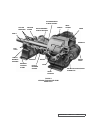
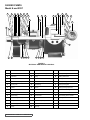
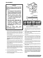
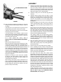
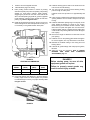
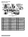
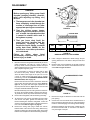
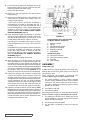
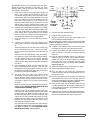
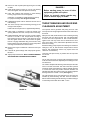
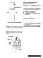
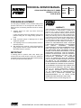
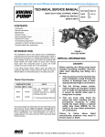
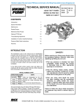
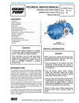
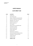
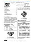
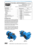
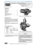
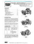
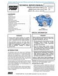
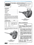
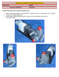
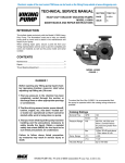
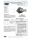
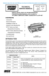
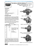
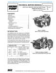
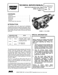
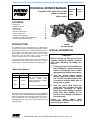
Electronic copies of the most current TSM issue can be found on the Viking Pump website at www.vikingpump.com
TECHNICAL SERVICE MANUAL
STAINLESS STEEL HEAVY DUTY PUMPS
SERIES 337 AND 4337
SIZES N and R
SECTION
TSM 163
PAGE
1 of 15
ISSUE
D
CONTENTS
Introduction . . . . . . . . . . . . . . . . . . . . . . . .1
Special Information . . . . . . . . . . . . . . . . . . . .1
Maintenance . . . . . . . . . . . . . . . . . . . . . . .2
Packed Pumps . . . . . . . . . . . . . . . . . . . . . .3
Mechanical Seal Pumps . . . . . . . . . . . . . . . . .8
Optional PTFE Seal . . . . . . . . . . . . . . . . . . 13
Thrust Bearing Adjustment . . . . . . . . . . . . . . . 14
Installation of Carbon Graphite Bushings . . . . . . . 14
Pressure Relief Valve Instructions . . . . . . . . . . . 15
INTRODUCTION
The illustrations used in this manual are for identification
purposes only and cannot be used for ordering parts. Obtain a
parts list from the factory or a Viking® representative. Always
give complete name of part, part number and material with
model number and serial number of pump when ordering
repair parts. The unmounted pump or pump unit model
number and serial number are on the nameplate.
In the Viking model number system, basic size letters are
combined with series number (337 and 4337) are used to
indicate either an unmounted pump or mounted pump unit.
Model Chart Number
UNMOUNTED PUMP
PACKED MECH. SEAL
N337
N4337
R337
R4337
UNITS
Units are designated by the
unmounted
pump
model
numbers followed by a letter(s)
indicating drive style.
P = Commercial Speed Reducer
This manual deals only with Series 337 and 4337 Stainless
Steel Heavy Duty Pumps. Refer to Figures 1 through 20 for
general configuration and nomenclature used in this manual.
Pump specifications and recommendations are listed in
Catalog Section 163, Series 337 and 4337 Heavy Duty Steel
External Pumps.
figure 1
R337 SIZE SHOWN
SPECIAL INFORMATION
DANGER !
Before opening any Viking pump liquid
chamber (pumping chamber, reservoir,
relief valve adjusting cap fitting, etc.)
Be sure:
1. That any pressure in the chamber has
been completely vented through the
suction or discharge lines or other
appropriate openings or connections.
2.That the driving means (motor,
turbine, engine, etc.) has been “locked
out” or made non-operational so that
it cannot be started while work is
being done on pump.
3.That you know what liquid the
pump has been handling and the
precautions necessary to safely
handle the liquid. Obtain a material
safety data sheet (MSDS) for the
liquid to be sure these precautions
are understood.
Failure
to
follow
above
listed
precautionary measures may result in
serious injury or death.
VIKING PUMP, INC. • A Unit of IDEX Corporation • Cedar Falls, IA 50613 USA
SPECIAL INFORMATION
ROTATION: Viking pumps operate equally well in a clockwise
or counterclockwise rotation. Shaft rotation determines which
port is suction and which is discharge. The suction port
location is where pumping elements (gear teeth) come out
of mesh.
FLUSH LINES: mechanically sealed pumps have a flush
connection from the seal chamber to the discharge port as
standard equipment and must be hooked up properly. If the
pump rotation is reversed, be sure the flush connections are
hooked up to the suction or discharge port as noted above to
avoid excessive leakage or damage to pump. If the pump is
handling heated product, be sure the flush line is insulated to
assure continued flow.
Jacketed head (R only, optional on N size) and rotor bearing
sleeve provide large chambers at both ends of the pumping
chamber for temperature control of product in pump. These
features do not alter basic steps in the disassembly and
assembly of your pump.
PRESSURE RELIEF VALVES:
1. Viking pumps are positive displacement pumps and must
be provided with some sort of pressure protection. This
may be a relief valve mounted directly on the pump, an
inline pressure relief valve, a torque limiting device or a
rupture disk.
2. Relief valve options are available on these pumps.
Options include plain and jacketed relief valvs. N size
pumps with a jacketed head are not available with a
relief valve.
3.If the pump rotation is to be reversed during operation,
pressure protection must be provided on both sides of
pump.
4. Relief valve adjusting screw cap must always point
towards suction side of pump. If pump rotation is
reversed, remove the pressure relief valve and turn end
for end. Refer to Figure 2 below.
5. Pressure relief valves cannot be used to control the
pump flow or regulate discharge pressure.
For additional information on pressure relief valves, refer to
Technical Service Manual TSM000 and Engineering Service
Bulletin ESB-31.
SPECIAL MECHANICAL SEALS: can be installed in a
modified stuffing box.
Extra care must be taken in repair of pumps with mechanical
seals. Read and follow all special information supplied with
the pump.
MAINTENANCE
Series 337 and 4337 pumps are designed for long trouble
free life under a wide variety of application conditions with a
minimum of maintenance. The points listed below will help
provide long service life.
LUBRICATION: External lubrication must be applied slowly
with a handgun to all lubrication fittings every 500 hours of
operation with multi-purpose grease, NLGI # 2. Do not overgrease. Applications involving very high or low temperatures
will require other types of lubrication. Refer to Engineering
Service Bulletin ESB-515. Consult factory with specific
lubrication questions.
PACKING ADJUSTMENT: New packed pumps require
initial packing adjustment to control leakage as packing
“runs in”. Make initial adjustments carefully and do not overtighten packing gland. After initial adjustment, inspection
will reveal the need for packing gland adjustment or packing
replacement. Refer to instructions under DISASSEMBLY,
page 5, and Assembly, page 6, regarding repacking the
pump.
CLEANING PUMP: Keep the pump as clean as possible.
This will facilitate inspection; adjustment and repair work and
help prevent overlooking a dirt covered grease fitting.
STORAGE: If the pump is to be stored, or not used for six
months or more, pump must be drained and a light coat
of non-detergent SAE 30 weight oil must be applied to all
internal pump parts. Lubricate fittings and apply grease
to the pump shaft extension. Viking suggests rotating the
pump shaft by hand one complete revolution every 30 days
to circulate the oil.
SUGGESTED REPAIR TOOLS: The following tools must
be available to properly repair Series 337 and 4337 pumps.
These tools are in addition to standard mechanics’ tools such
as open end wrenches, pliers, screwdrivers etc. Most of the
items can be obtained from an industrial supply house.
1. Soft Headed Hammer
outlet
or
suction
inlet
or
suction
2. Allen Wrenches (some mechanical seals and set
collars)
3. Packing hooks, flexible (packed pumps)
Large for 0.375 inch and up cross section packing
4. Bearing locknut spanner wrench
(Source: #471 J.H. Williams & Co. or equal)
relief
valve
adjusting
screw
Spanner wrench (Supplied with pump)
Viking Part Number 3-810-009-631
6.
Brass Bar
7. Arbor Press
figure 2
SECTION TSM 163
5.
ISSUE
D
PAGE 2 OF 15
rotor bearing
sleeve gasket
roller
bearings
packing
gland
rotor bearing
sleeve bushing
casing
Head
gasket
Head
Shaft
idler pin
end
caps
thrust
bearing
housing
bearing
housing
stand
relief
valve
rotor
packing
rotor
bearing
sleeve
idler
relief valve adjusting
screw cap
idler
bushing
figure 3
CUTAWAY FROM PACKED PUMP
MODEL N337
SECTION TSM 163
ISSUE
D
PAGE 3 OF 15
PACKED PUMPS
Model N and R337
4
6
5
8
7
8
9
6
7
4
5
29
28
18
11
9
13
16
15
36 17
37
19
21
20
22
24
14
23
12
25
26
2
3
38
1
27
10 32 30 31
33 34 35 36
figure 4
SECTIONAL VIEW MODELS N AND R337
ITEM
NAME OF PART
ITEM
NAME OF PART
ITEM
NAME OF PART
1
Locknut
14
Bushing, Rotor Bearing Sleeve
27
Bearing Housing Stand
2
Lockwasher
15
Casing
28
Packing Gland Stud
3
Bearing Spacer Collar
16
Rotor and Shaft
29
Packing Gland Nut
4
Capscrew for End Cap Lock
17
Idler and Bushing
30
Bearing Housing Stud
5
End Cap Lock
18
Idler Bushing
31
Bearing Housing Nut
6
Lip Seal
19
Idler Pin
32
Bearing Housing Capscrew
7
End Cap
20
Head and Idler Pin
33
Stud for Rotor Bearing Sleeve
8
Roller Bearing
21
Nut for Head
34
Nut for Rotor Bearing Sleeve
9
Grease Fitting
22
Stud for Head
35
Rotor Bearing Sleeve Gasket
10
Thrust Bearing Housing
23
Capscrew for Valve
36
Pipe Plug
11
Packing Gland
24
Idler Pin Nut (Not N)
37
Head Gasket
12
Rotor Bearing Sleeve & Bushing
25
Internal Relief Valve
38
Relief Valve Gasket
13
Packing
26
Pipe Plug
SECTION TSM 163
ISSUE
D
PAGE 4 OF 15
DISASSEMBLY
DANGER !
Before opening any Viking pump liquid
chamber (pumping chamber, reservoir,
relief valve adjusting cap fitting, etc.)
Be sure:
1. That any pressure in the chamber has
been completely vented through the
suction or discharge lines or other
appropriate openings or connections.
jackscrews
figure 5
2.That the driving means (motor,
turbine, engine, etc.) has been “locked
out” or made non-operational so that
it cannot be started while work is
being done on pump.
3.That you know what liquid the
pump has been handling and the
precautions necessary to safely
handle the liquid. Obtain a material
safety data sheet (MSDS) for the
liquid to be sure these precautions
are understood.
Failure
to
follow
above
listed
precautionary measures may result in
serious injury or death.
1. Mark the head and casing before disassembly to ensure
proper reassembly. The idler pin, which is offset in pump
head, must be positioned towards and equal distance
between the port connections to allow for proper flow of
liquid through pump.
It is not necessary to remove relief valve to take head
off pump; however, removing relief valve will lessen total
weight of part. Do not use chain or cable around relief
valve body to support the head during removal. For
PRESSURE RELIEF VALVE INSTRUCTIONS, refer to
page 14.
Remove nuts from the head. Jackscrews should be
used to back head away from casing. Refer to figure 5.
Proper size and length of jackscrews for pump size are
shown in figure 6. The use of a hoist to support head will
facilitate its removal.
Back the head away from casing. Remove the head from
pump. Do not allow the idler to fall from the idler pin. To
prevent this, tilt the top of head back when removing. If a
hoist is not available, cribbing or blocking can be used to
support head. This will eliminate having to lift head into
position when reassembling pump.
2.Remove the head gasket, idler and bushing assembly.
3. Remove the pipe plug from the drain hole in the casing,
this breaks the vacuum behind rotor.
4. Remove the packing gland nuts and slide the gland out
of the rotor bearing sleeve.
thread size
a
PUMP
SIZE
NO. SCREWS
USED
A
THREAD SIZE
(INCH)
N
R
2
2
4.00
4.50
0.50” - 13 NC
0.63” - 11 NC
FIGURE 6
MINIMUM LENGTH OF JACK SCREWS
5. Insert length of hard wood or brass bar through the port
opening between the rotor teeth to keep the shaft from
turning.
6. Bend the tang on the lock washer up and with a spanner
wrench; remove locknut and lockwasher from the shaft.
Refer to figure 7, page 6.
7. Remove the length of hardwood or brass bar from the
port opening.
8. Cushion the end of the shaft with a hardwood block or
piece of block and drive the rotor out of casing, being
careful to avoid damaging the rotor bearing sleeve
bushing. Support the weight of rotor with a hoist. A cable
sling can be used around the shaft, or around rotor teeth,
to carry weight of the part.
9. Loosen the end cap lockscrews, disengage the end cap
locks and with a spanner wrench remove the end caps.
Remove the roller bearings.
10. Remove the nuts and capscrews and take off the thrust
bearing housing. Remove the packing from the rotor
bearing sleeve.
11. Check the rotor bearing sleeve bushing while the rotor
bearing sleeve is mounted on the casing. If worn, the
bushing must be replaced. Remove the rotor bearing
sleeve from casing. A press must be used to remove the
old bushing. If bushing has a shoulder on the stuffing box
end, it must be pressed out from the packing end of rotor
bearing sleeve. If bushing is carbon graphite, refer to
INSTALLATION OF CARBON GRAPHITE BUSHINGS,
page 13.
SECTION TSM 163
ISSUE
D
PAGE 5 OF 15
ASSEMBLY
LOCKWASHER WITH TANG
2.Check the casing to be sure the drain plug has been
removed.
LOCKNUT
3. Carefully check the shaft, remove any burrs or rough
surfaces to avoid damaging the rotor bearing sleeve
bushing while installing the rotor and shaft into the casing.
Coat the inner diameter of the rotor bearing sleeve
bushing and shaft with a thin coat of non-detergent SAE
30 weight oil.
figure 7
12. Clean all parts thoroughly and examine for wear and
damage. Check the idler bushing and idler pin, replace if
necessary.
If the idler pin is to be replaced, the oil groove must be
installed facing center of the crescent on the head.
If lipseals need replacement, press in the end cap with
the lip facing the end of the shaft.
If the idler bushing is to be replaced, a press must be
used to remove the old bushing and install the new one.
The bushing position after being pressed in should be
flush with the face of the idler.
For a carbon graphite idler bushing, refer to
INSTALLATION OF CARBON GRAPHITE BUSHINGS,
page 13.
NOTE: R idler bushings are shrink fit.
Wash the anti-friction bearings (roller bearings) in clean
solvent. Blow out the bearings with compressed air. Do
not allow the bearings to spin; turn the bearings slowly
by hand. Spinning the bearings will damage the race and
rollers. Make sure the bearings are clean, then lubricate
with non-detergent SAE 30 weight oil and check for
roughness. Roughness can be determined by turning the
outer race by hand. CAUTION: do not intermix inner and
outer races for the roller bearings. Replace the bearings
if they have roughness.
Examine the casing for wear. Check the condition
of casing at seal area (surface between suction and
discharge port). If the surface is in good condition, the
casing need not be replaced.
When making major repairs, such as replacement
rotor, it is usually considered advisable to install a
head and idler. When making minor repairs, where
an idler bushing and idler pin are required, other
parts are usually not necessary.
1. Install the rotor bearing sleeve and gasket on the casing.
Coat both sides of the gasket with thread sealant (pipe
dope) and quickly install the gasket and rotor bearing
sleeve on the casing. Place a support under rotor bearing
sleeve to prevent casing and rotor bearing sleeve from
tilting down while the rotor is being installed.
of a
new
only
new
Support the weight of the rotor with a hoist. A cable sling
can be used around the shaft, or around rotor teeth, to
carry weight of the part while being assembled into the
casing.
Place end of the rotor shaft through the casing, into the
bushing slowly turn rotor from right to left while pushing
into casing. When the shaft first protrudes from stuffing
box, stop pushing. Check to see if the large diameter
of the shaft has protruded far enough into rotor bearing
sleeve to permit installing packing rings.
Use packing suitable for the liquid being pumped.
Lubricate packing rings with oil, grease or graphite to aid
assembly. Packing ring joints should be staggered from
one side of shaft to the other. A length of pipe will help
set each packing ring.
4.Place the packing gland and inner end cap (position
spanner wrench holes on side next to packing gland)
with lip seal (lip facing away from packing gland) over
the end of the shaft.
5.Push the rotor far into the casing as far as it will go.
6. Prior to installing the head, coat the casing face with
thread sealant (pipe dope) and place a new .015” head
gasket on the mounting studs. Coat the dry side of
gasket with thread sealant (pipe dope) and prepare to
mount the head and idler assembly.
The pump head and casing were marked before
disassembly to ensure proper reassembly. If not, be sure
idler pin, which is offset in the pump head, is positioned
toward and equal distance between the port connections
to allow for proper flow of liquid through the pump. Place
the head on the pump, slightly tilting the top of the head
back away from casing until the crescent enters the
inside diameter of rotor. Rotate the idler on idler pin until
the idler teeth mesh with the rotor teeth. Raise head until
the face of the head is parallel with face of the casing
and work into position. Care must be taken to avoid
damaging the head gasket. Fasten the head to casing
with nuts and tighten evenly.
If relief valve was not removed from head, install on
head with adjusting screw cap pointed toward such port.
Refer to Figure 2, page 2. For PRESSURE RELIEF
INSTRUCTIONS, refer to page 14.
SECTION TSM 163
ISSUE
D
PAGE 6 OF 15
7.
Push the rotor back against the head.
8.
Install the drain plug in the casing.
12. Install the bearing spacer collar on the shaft next to the
inner race of the roller bearing.
9. Place packing retainer washer in bottom of packing
chamber and pack pump with new packing. Use packing
suitable for liquid being pumped. Install packing,
staggering the joints from one side of the shaft to the
other. Lubricate packing rings with oil, grease or graphite
to aid assembly. A length of pipe will help to seat each
packing ring. Refer to Figure 8 below.
13. Turn the inner end cap into the thrust bearing housing
just far enough to hold in place.
10.Install the thrust bearing housing on the end of rotor ring
sleeve and tighten the nuts and capscrews securely. It is
not necessary to use gasket between these parts.
15. Install the lockwasher placing tang in the keyway on the
shaft. Tighten the locknut to 170-190 ft – lbs. Torque.
Bend one tang of lock washer into slot of locknut. If tang
does not line up with slot tighten lock nut until it does.
Failure to tighten locknut or engage the lock washer tang
could result in early bearing failure and cause damage to
rest of pump.
Install the outer end cap and turn in approximately half
way.
14. Insert a length of hardwood or brass bar through the port
opening between the rotor teeth to keep the rotor from
turning.
16. Remove the length of hardwood or brass bar from the
port opening.
17.Install the nuts on the packing gland studs and tighten.
Do not over tighten, as it may cause bind on rotor shaft.
c
18.Reinstall the suckback tubing to the casing and rotor
bearing sleeve.
B
19. Lubricate all grease fittings with multi-purpose grease,
NLGI #2.
20.Adjust the pump end clearance. Refer to THRUST
BEARING
AND
IDLER
END
CLEARANCE
ADJUSTMENT, page 12.
a
DANGER !
figure 8
STUFFING BOX DIMENSIONS
PUMP
MODEL
A
(INCH)
B
(INCH)
C
(INCH)
N337
4.63”
4.69”
3.44”
R337
4.63”
4.69”
3.44”
Before starting pump, be sure all drive
equipment guards are in place.
Failure to properly mount guards may
result in serious injury or death.
11. Insert both tapered roller bearings in the thrust bearing
housing, large end of inner races together. It is possible
to install bearings incorrectly, for proper assembly refer
to Figure 9 below.
figure 9
SECTION TSM 163
ISSUE
D
PAGE 7 OF 15
MECHANICAL SEAL PUMPS
Models N and R4337
4
6
5
8
7
8
9
6
7
4
5
12
11
17 16 19
14
13
15
18
20
35
22 23 24 36 25 26
21
27 37 28 30
29
35
3
2
1
31 10
32 33 34 35
SECTIONAL VIEW MODELS N AND R4337
FIGURE 10
ITEM
NAME OF PART
ITEM
NAME OF PART
ITEM
NAME OF PART
1
Locknut
15
Packing Box Extension
29
Bearing Housing Stand
2
Lockwasher
16
Mechanical Seal (Complete)
30
Stud for Rotor Bearing Stand
3
Bearing Spacer Collar
17
Rotor Bearing Sleeve
31
Nut for Rotor Bearing Sleeve
4
Capscrew for End Cap Lock
18
Bushing, Rotor Bearing Sleeve
32
Rotor Bearing Sleeve Gasket
5
End Cap Lock
19
Casing
33
Pipe Plug
6
Lip Seal
20
Rotor and Shaft
34
Head Gasket
7
End Cap
21
Idler
35
Relief Valve Gasket
8
Roller Bearing
22
Idler Bushing
36
Bearing Housing Stud
9
Grease Fitting
23
Idler Pin
37
Bearing Housing Nut
10
Thrust Bearing Housing
24
Head
38
Capscrew for Bearing Housing
11
Stud for Seal Plate
25
Nut for Head
N.I.
Pipe Flange Gasket
12
Nut for Seal Plate
26
Stud for Head
N.I.
Stud for Flanges
13
Seal Holder Plate
27
Capscrew for Valve
N.I.
Nut for Flanges
14
Gasket for Packing Box Extension
28
Internal Relief Valve (Complete)
SECTION TSM 163
ISSUE
D
PAGE 8 OF 15
DISASSEMBLY
DANGER !
Before opening any Viking pump liquid
chamber (pumping chamber, reservoir,
relief valve adjusting cap fitting, etc.)
Be sure:
1. That any pressure in the chamber has
been completely vented through the
suction or discharge lines or other
appropriate openings or connections.
jackscrews
figure 11
2.That the driving means (motor,
turbine, engine, etc.) has been “locked
out” or made non-operational so that
it cannot be started while work is
being done on pump.
3.That you know what liquid the
pump has been handling and the
precautions necessary to safely
handle the liquid. Obtain a material
safety data sheet (MSDS) for the
liquid to be sure these precautions
are understood.
Failure
to
follow
above
listed
precautionary measures may result in
serious injury or death.
1. Mark the head and casing before disassembly to ensure
proper reassembly. The idler pin, which is offset in
the pump head, must be positioned toward and equal
distance between the port connections to allow for proper
flow of liquid through the pump.
It is not necessary to remove the relief valve to take
the head off the pump; however, removing the relief
valve will lessen total weight of the part. Do not use
a chain or cable around relief valve body to support
head during removal. For PRESSURE RELIEF VALVE
INSTRUCTIONS, refer to page 14.
thread size
a
PUMP
SIZE
NO. SCREWS
USED
A
THREAD SIZE
(INCH)
N
R
2
2
4.00
4.50
0.50” - 13 NC
0.63” - 11 NC
FIGURE 12
MINIMUM LENGTH OF JACK SCREWS
5. Insert a length of hardwood or brass through the port
opening between the rotor teeth to keep the shaft from
turning.
6. Bend the tang on the lockwasher up and with a spanner
wrench, remove the locknut and lockwasher from the
shaft. Refer to figure 13 below.
LOCKWASHER WITH TANG
Remove the nuts from the head. Jackscrews should be
used to back the head away from the casing. Refer to
figure 11. The proper size and length of jackscrews for
the pump size are shown in figure 12. The use of a hoist
to support head will facilitate its removal.
Back the head away from the casing. Remove head from
the pump. Do not allow the idler to fall from the idler pin.
To prevent this, tilt the top of head back when removing.
2.Remove the head gasket, idler and bushing assembly.
3. To remove the rotor, remove seal plate nuts from studs
and remove seal plate, gaskets and stationary seat.
Remove Packing box extension and gasket. Loosen set
screws in mechanical seal retainer cartridge and remove
from rotor shaft. Refer to Figure 14, page 10.
4. Remove the casing drain plug to break the vacuum
between back of the rotor and the casing. Remove any
deposit of material from the exposed portion of the shaft
between the seal plate and the thrust bearing assembly.
LOCKNUT
figure 13
7. Remove the length of hardwood or brass bar from the
port opening.
8. Cushion the end of the shaft with a hardwood block or
piece of brass and drive the rotor out of the casing being
careful to avoid damaging rotor bearing sleeve bushing.
Support the weight of rotor with a hoist. A cable sling can
be used around the shaft, or around the rotor teeth to
carry the weight of the part.
SECTION TSM 163
ISSUE
D
PAGE 9 OF 15
9. Loosen the end cap lockscrews, disengage the end cap
locks and with a spanner wrench, remove the end caps.
Examine the lipseal and replace if worn.
Remove the roller bearings.
10. Remove the nuts and capscrews and take off thrust
bearing housing.
11. Check the rotor bearing sleeve bushing while the rotor
bearing sleeve is mounted on the casing. If worn, the
bushing must be replaced.
A press must be used to remove the old bushing. If
the bushing has a shoulder on the stuffing box end, it
must be pressed out from the mechanical seal end of
the rotor bearing sleeve. Carbon graphite bushings are
standard for model 4337 pumps. To replace carbon
graphite bushings, refer to INSTALLATION CARBON
GRAPHITE BUSHINGS, page 13.
12. Clean all parts thoroughly and examine for wear and
damage. If lipseal replacement is needed, press in the
end cap with the lip facing the end of the shaft. Check
the idler bushing and idler pin, replace if necessary.
If the idler pin is to be replaced, the oil grove on the pin
must be installed facing the center of the crescent on
the head.
If the idler bushing is to be replaced, a press must be used
to move the old bushing and install new. The bushing
position after being pressed in should be flush with
the face of the idler. For carbon graphite idler bushing,
refer to INSTALLATION OF CARBON GRAPHITE
BUSHINGS, page 13.
NOTE: R size idler bushings are shrink fit
13.Wash the bearing in clean solvent. Blow out bearings
with compressed air. Do not allow bearings to spin; turn
the bearing slowly by hand. Spinning the bearings will
damage the race and rollers. Make sure the bearings are
clean, then lubricate with non-detergent SAE 30 weight oil
and check for roughness. Roughness can be determined
by turning the outer race by hand. CAUTION: do not
intermix the inner and outer races for the roller bearings.
14.Examine the casing for wear. Check the condition of the
casing at the seal area (surface between suction and
discharge ports). If the surface is in good condition, the
casing need not be replaced. When making major repairs,
such as replacement of a rotor, it is usually considered
advisable to install a new head and idler. When making
minor repairs, when only an idler bushing and idler pin
are required, other new parts are usually not necessary.
15. Inspect the mechanical seal for wear or damage. Refer
to figure 14 for mechanical seal list of parts. In general, if
the pump has been operated long enough to exhibit other
worn parts, it is likely the seal will have to be replaced.
Replacing individual seal parts is not recommended, i.e.,
a used seal washer will not perform satisfactorily when
run against a new stationary seat.
SHAFT
figure 14
PTFE Fitted Mechanical Seal Assembly
For Models N-R4333, 4335 & 4337
1. Retainer Cartridge
2.Springs
3. PTFE Shaft Ring (wedge)
4. Rotating Face (washer)
5. Stationary Seal Seat
6. Seat Gaskets
Seal Mounting Parts
A.
B.
C.
D.
Packing box extension
Packing box extension gasket
Seal plate
Flush openings
ASSEMBLY
(PTFE Fitted Type)
Prepare all parts for reassembly ahead of time. Pack roller
bearings with multi-purpose grease, NLGI # 2 and have all
new gaskets on hand.
Three components are furnished in mechanical seal
assembly: Refer to figure 14, item numbers 1 thru 6.
1. The rotating assembly in which a retainer cartridge
encloses a spring loaded PTFE shaft ring and polished
rotating face. Set screws located around the outside of
the retainer cartridge are provided for securing rotating
assembly to pump shaft.
2. The stationary seal seat.
3. Two seal seat gaskets.
Three pump parts necessary for mounting PTFE mechanical
seal are illustrated in figure 14, item letters A, B, C and D.
1. The packing box extension has a machine pilot on the
end for installation in the rotor bearing sleeve and two
tapped holes for the seal flush.
2. The packing box extension gasket.
3. The seal plate is machined to accept seal seat and
gasket.
SECTION TSM 163
ISSUE
D
PAGE 10 OF 15
Be especially careful to keep mechanical seal parts clean.
Minute dirt particles especially on seal faces, will cause
leakage. Never touch the seal faces with anything except
clean hands or a clean cloth.
inlet
or
suction
1.Deburr the threads on the rotor shaft with a fine file and
place a layer of tape over the threads to protect the
rotor bearing sleeve bushing during assembly. Gently
radius leading edge of the largest diameter on the shaft
(.03 inch is sufficient to aid in seal installation). Smooth
radius with a very fine grit emery cloth. Polish the rotor
shaft from leading edge through mechanical seal area
with the emery cloth. Any scratches left on shaft in seal
area will provide leakage paths under mechanical seal.
relief
valve
adjusting
screw
2.Install the rotor bearing sleeve and gasket on the casing.
Coat both sides of the gasket with thread sealant (pipe
dope) and quickly install the gasket and rotor bearing
on the casing. Place a support under the rotor bearing
sleeve to prevent the casing and rotor bearing sleeve
from tilting down while the rotor is being installed.
3.Check the casing to be sure the drain plug has been
removed.
4.Coat the inner diameter of the rotor bearing sleeve
bushing with a thin coat of non-detergent SAE30 weight
oil.
Support the weight of the rotor with a hoist. A cable sling
can be used around the shaft, or around rotor teeth,
to carry weight of part while being assembled into the
casing.
Place the end of rotor shaft through casing into bushing.
Do not allow any portion of the shaft to strike the bushing.
A carbon graphite bushing can be severely damaged
if struck. Slowly turn the rotor from right to left while
pushing into the casing. Push the rotor as far into casing
as it will go.
5. Prior to installing the head, coat the casing face with
thread sealant (pipe dope) and place a new .015 inch
head gasket on the mounting studs. Coat the dry side of
the gasket with thread sealant (pipe dope) and prepare
to mount the head and idler assembly.
6. The pump head and casing were marked before
disassembly to ensure proper reassembly. If not, be
sure the idler pin, which is off set in the pump head, is
positioned toward and equal distance between the port
connections to allow for an even flow of liquid through
the pump.
NOTE: The R4337 pump has a special idler arrangement,
refer to section THRUST BEARING AND IDLER END
CLEARANCE ADJUSTMENT, page 12.
Place the head on pump, slightly tilting top of the head
back away from casing until the crescent enters inside
diameter of the rotor. Rotate the idler on idler pin until
the idler teeth mesh with the rotor teeth. Raise the head
until the face of head is parallel with the face of casing
and then work into position. Care must be taken to avoid
damaging the head gasket. Fasten the head to casing
with head nuts and tighten evenly.
outlet
or
suction
figure 15
7.Push the rotor back against the head.
8.Install the drain plug in the casing.
9.Wipe the shaft clean in seal area and thoroughly coat
with non-detergent SAE 30 weight oil.
Before installing parts contained in the mechanical seal, refer
to figure 14, page 10 to become familiar with part name and
location in packing box extension.
10. A tapered seal installation sleeve for N & R size pumps
is available, at extra cost, from Viking pump Division.
11.Coat the large diameter of shaft, tapered sleeve, and
inside of diameter of seal with non-detergent SAE 30
weight oil.
12.Place the tapered installation sleeve (if on hand) and
install the seal on the shaft over the tapered sleeve.
Position the seal on the shaft inside the rotor bearing
sleeve bore with end of seal located 0.19 inch inside
the machined face of the rotor bearing sleeve. Refer to
Figure 14, page 10.
13. Tighten all seal drive set screws securely to the shaft.
14.Remove the tapered installation sleeve.
15.Place the gasket on the packing box extension and
install the extension with machined pilot inside the rotor
bearing sleeve bore.
16.Place the seat gasket over the shoulder of the stationary
seal seat and insert seat into the seal plate. Place the
remaining seat gasket over shoulder of polished surface
of stationary seat. Refer to Figure 14, page 10.
17.Place the seal plate with the stationary seat over the
mounting studs and push the shoulder of stationary seat
into the packing box extension, the polished face against
the carbon rotating face.
18.Install the nuts on mounting studs and against seal holder.
Tighten the nuts evenly so the seal plate and stationary
seat will not be distorted when seal is compressed.
If the relief valve was removed from the head, install on
head with the adjusting screw cap pointed toward suction
port. Refer to figure 15. For PRESSURE RELIEF
VALVE INSTRUCTIONS, refer to page 14.
SECTION TSM 163
ISSUE
D
PAGE 11 OF 15
19. Place inner end cap with lipseal (lip facing end of shaft)
on shaft.
20. Install thrust bearing housing on end of rotor bearing
sleeve and tighten nuts and capscrews securely.
21.Insert both tapered roller bearings in thrust bearing
housing, large end of inner races together.
CAUTION: It is possible to install bearings incorrectly.
For proper assembly, refer to figure 16 below.
22. Install bearing spacer collar on shaft next to inner race of
roller bearing.
23. Turn inner end cap into thrust bearing housing just far
enough to hold in place.
Install outer end cap and turn in approximately halfway.
24.Insert length of hardwood or brass bar through port
opening between rotor teeth, to keep rotor from turning.
25. Install lockwasher with tang in keyway on shaft. Tighten
locknut to 170-190 ft – lbs. Torque. Bend one tang of
lock washer into slot of locknut. If tang does not line up
with slot, tighten locknut until it does. Failure to tighten
locknut or engage lockwasher tang could result in early
bearing failure and cause damage to rest of pump. Bend
one tang of lockwasher into slot of locknut.
26.Remove the length of hardwood or brass bar from port
opening.
27. Lubricate all grease fittings with multi-purpose grease,
NLGI # 2.
28. Adjust pump end clearance. Refer to THRUST BEARING
AND IDLER END CLEARANCE ADJUSTMENT.
DANGER !
Before starting pump, be sure all drive
equipment guards are in place.
Failure to properly mount guards may
result in serious injury or death.
THRUST BEARING AND IDLER END
CLEARANCE ADJUSTMENT
Use spanner wrench (provided with pump) and turn outer
end cap until rotor is tight against head and rotor shaft cannot
be turned.
With pencil or chalk, make reference mark on bearing housing
and outer end cap. Back off outer end cap approximately
4 holes. One hole is equivalent to .005” of end clearance.
Tighten inner end cap. Check rotor to determine if it turns
freely in the casing. If not, make further adjustment until rotor
does turn in casing.
Standard catalog pumps require the following end clearance
settings; N, .015”, R, .020” minimum. Pumps built for viscous
liquid or high temperature service may require extra end
clearance. Consult factory.
Lock both end caps securely in position with end cap locks
and screws.
NOTE:
The R 4337 pump has a special idler arrangement which
must have its end clearance adjusted prior to setting the rotor
end clearance.
The Carbon Graphite idler bushing extends beyond the idler
face on one side of the idler. This side of the idler is placed
toward the head which allows the Carbon Graphite bushing
to contact the head and provide clearance between the
stainless steel idler face and the head. The Carbon Graphite
bushing extension is 0.008 – 0.012” (See Figure 1).
The idler bushing has a high interference fit and must be
installed by heat shrinking. The idler must be heated to
600 ºF before installing the idler bushing. The idler bushing is
to extend beyond the idler face 0.008 – 0.012”.
figure 16
SECTION TSM 163
ISSUE
D
PAGE 12 OF 15
0.012
0.008
bushing extension
beyond idler face
INSTALLATION OF CARBON
GRAPHITE BUSHINGS
When installing carbon graphite bushings, extreme care
must be taken to prevent breaking. Carbon graphite is a
brittle material and easily cracked. If cracked, the bushing will
quickly disintegrate. Using a lubricant and adding a chamfer
on the bushing and the mating part will help with installation.
The additional precautions listed below must be followed for
proper installation:
1. A press must be used for installation.
rotor
this
side
head
this
side
2. Be certain the bushing is started straight.
3. Do not stop the pressing operation until the bushing is in
the proper position; starting and stopping will result in a
cracked bushing.
4.Check the bushing for cracks after installation.
Carbon graphite bushings with extra interference fits are
frequently furnished for high temperature operation. These
bushings must be installed by a shrink fit.
1. Heat the rotor bearing sleeve or idler to 750 °F.
2. Install cool bushings with a press.
figure 17 - Idler and bushing assembly
Install the idler & bushing over the idler pin placing the side
of the idler with the bushing extension against the head
(See Figure 18 below). Place a 0.010” shim stock between
the idler bushing and the head. This provides 0.010” of end
clearance between the ends of the idler bushing and the
mating surfaces (head and idler pin locknut). Install idler pin
locknut and turn clockwise until it touches the idler bushing.
Tighten the three setscrews in the face of the idler pin
locknut to lock it against the idler pin. Remove the 0.010”
shim stock.
3. If facilities are not available to reach 750 °F. temperature,
it is possible to install with 450 °F. temperature; however,
the lower the temperature, the greater the possibility of
cracking the bushing.
Consult factory with specific questions on high temperature
applications. Refer to Engineering Service Bulletin ESB-3.
0.010” shim stock
idler pin
locknut
setscrews (3)
figure 18
SECTION TSM 163
ISSUE
D
PAGE 13 OF 15
PRESSURE RELIEF VALVE
INSTRUCTIONS
Mark valve and head before disassembly to ensure proper
reassembly.
1.Remove the valve cap.
2. Measure and record the length of extension of adjusting
screw. Refer to “A” on Figure 19.
3.Loosen the locknut and back out the adjusting screw
until the spring pressure is being released.
4.Remove the bonnet, spring guide, spring and poppet
from the valve body. Clean and inspect all parts for wear
and damage and replace as necessary.
ASSEMBLY
Reverse the procedures outlined under DISASSEMBLY. If the
valve is removed for repairs, be sure to replace in the same
position. The relief valve adjusting screw cap must always
point towards suction side of the pump. If pump rotation is
reversed, remove the relief valve and turn end for end. Refer
to Figure 20 below.
FIGURE 19
Sizes N and R
LIST OF PARTS
1. Valve Cap
6.
Valve Body
2. Adjusting Screw
7.
Valve Spring
3. Lock Nut
8.
Poppet
4. Spring Guide
9.
Cap Gasket
5. Bonnet
10.
Bonnet
DANGER !
Before opening any Viking pump liquid
chamber (pumping chamber, reservoir,
relief valve adjusting cap fitting, etc.)
Be sure:
1. That any pressure in the chamber has
been completely vented through the
suction or discharge lines or other
appropriate openings or connections.
2.That the driving means (motor,
turbine, engine, etc.) has been “locked
out” or made non-operational so that
it cannot be started while work is
being done on pump.
3.That you know what liquid the
pump has been handling and the
precautions necessary to safely
handle the liquid. Obtain a material
safety data sheet (MSDS) for the
liquid to be sure these precautions
are understood.
Failure
to
follow
above
listed
precautionary measures may result in
serious injury or death.
ISSUE
Before starting pump, be sure all drive
equipment guards are in place.
Failure to properly mount guards may
result in serious injury or death.
DISASSEMBLY
SECTION TSM 163
DANGER !
D
PAGE 14 OF 15
inlet
or
suction
outlet
or
suction
relief
valve
adjusting
screw
figure 20
TECHNICAL SERVICE MANUAL
stainless steel HEAVY-DUTY PUMPS
SERIES 337 AND 4337
SIZES n and r
SECTION
TSM 163
PAGE
15 of 15
ISSUE
D
PRESSURE ADJUSTMENT
If a new spring is installed or if the pressure setting of the
pressure relief valve is to be changed from that which the
factory has set, the following instructions must be carefully
followed.
1. Carefully remove the valve cap which covers the
adjusting screw.
Loosen the locknut which locks adjusting screw so the
pressure setting will not change during operation of
pump.
2. Install a pressure gauge in discharge line for actual
adjustment operation.
3. Turn adjusting screw in to increase pressure and out to
decrease pressure.
4. With discharge line closed at a point beyond pressure
gauge, gauge will show maximum pressure valve will
allow while pump is in operation.
IMPORTANT
In ordering parts for pressure relief valve, always give
model number and serial number of pump as it appears on
nameplate and name of part wanted. When ordering springs,
be sure to give pressure setting desired.
WARRANTY
Viking warrants all products manufactured by it to be
free from defects in workmanship or material for a
period of one (1) year from date of startup, provided
that in no event shall this warranty extend more than
eighteen (18) months from the date of shipment from
Viking. The warranty period for Universal Seal series
pumps ONLY (Universal Seal models listed below) is
three (3) years from date of startup, provided that in
no event shall this warranty extend more than forty-two
(42) months from the date of shipment from Viking.
UNDER NO CIRCUMSTANCES SHALL VIKING BE
LIABLE UNDER THIS WARRANTY OR OTHERWISE
FOR
SPECIAL,
INCIDENTAL,
INDIRECT,
CONSEQUENTIAL OR PUNITIVE DAMAGES OF ANY
KIND, INCLUDING, BUT NOT LIMITED TO, LOST
OR UNREALIZED SALES, REVENUES, PROFITS,
INCOME, COST SAVINGS OR BUSINESS, LOST OR
UNREALIZED CONTRACTS, LOSS OF GOODWILL,
DAMAGE TO REPUTATION, LOSS OF PROPERTY,
LOSS OF INFORMATION OR DATA, LOSS OF
PRODUCTION, DOWNTIME, OR INCREASED
COSTS, IN CONNECTION WITH ANY PRODUCT,
EVEN IF VIKING HAS BEEN ADVISED OR PLACED
ON NOTICE OF THE POSSIBILITY OF SUCH
DAMAGES AND NOTWITHSTANDING THE FAILURE
OF ANY ESSENTIAL PURPOSE OF ANY PRODUCT.
THIS WARRANTY IS AND SHALL BE VIKING’S SOLE
AND EXCLUSIVE WARRANTY AND SHALL BE IN
LIEU OF ALL OTHER WARRANTIES, EXPRESS
OR IMPLIED, INCLUDING, BUT NOT LIMITED
TO, ALL WARRANTIES OF MERCHANTABILITY,
FITNESS FOR A PARTICULAR PURPOSE AND
NON-INFRINGEMENT ALL OF WHICH OTHER
WARRANTIES ARE EXPRESSLY EXCLUDED.
See complete warranty at www.vikingpump.com.
VIKING PUMP, INC. • A Unit of IDEX Corporation • Cedar Falls, IA 50613 USA
© 3/2013 Viking Pump Inc.
All rights reserved