1
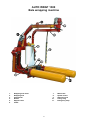
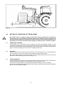
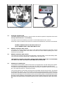
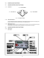
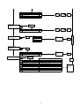
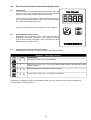
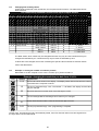
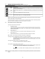
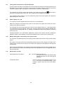
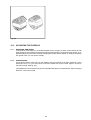
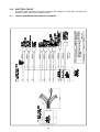
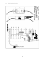
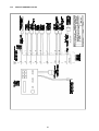
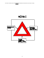
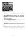
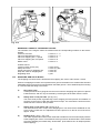
11 November 2002
1300E20.wpd
USER'S MANUAL
AUTO WRAP 1300
CHAP.
CONTENTS
PAGE
1.0
INTRODUCTION
3
2.0
SAFETY PRECAUTIONS
4
3.0
GENERAL INFORMATION ON BALEWRAPPING
8
4.0
SETTING UP / MOUNTING OF THE MACHINE
10
5.0
EMERGENCY STOP* (Instant stop)
13
6.0
MOUNTING OF PLASTIC FILM
14
7.0
REMOTE CONTROL UNIT
15
8.0
FLEX COUNTER
19
9.0
SPEED SETTING OF THE WRAPPING ARM
24
10.0
ADJUSTING THE OVERLAP
25
11.0
OPERATION INSTRUCTION
26
12.0
PERIODIC MAINTENANCE
27
13.0
ELECTRIC CIRCUT
28
14.0
DESCRIPTION OF HYDRAULICS
31
15.0
CHECK POINTS BEFORE TROUBLE SHOOTING
34
16.0
PROCEDURE OF TROUBLE SHOOTING
35
17.0
TROUBLE SHOOTING
36
18.0
HYDRAULIC CHART
37
19.0
WARRANTY TERMS
WARRANTY CARD
38
39
1
AUTO WRAP 1300 Bale wrapping machine
1.
2.
3.
4.
5.
6.
Wrapping arm motor
Wrapping arm
Prestretcher
Rollers
Support roller
Cutter
7.
8.
9.
10.
11.
2
Main frame
Speed control
Stationary arm
Lifting sling
Emergency stop*
1.0
INTRODUCTION.
TELLEFSDAL A.S congratulates you with the choice of AUTO WRAP bale wrapping machine. We
are certain you will be satisfied with the machine, and that you will have the pleasure of your
investment for many years.
The AUTO WRAP bale wrapping machine has more features than any other bale wrapping machine
available. AUTO WRAP can pick up the bale, wrap and stack them without the operator leaving the
tractor cab. This system is protected by patent law's almost world wide.
AUTO WRAP 1300 is hydraulically driven by the tractors hydraulic system, and is controlled from the
tractor cab by a remote control unit. The machine can either be mounted to three point linkage, front
mounted with quick-couplers to the tractors frontloader or on a wheel loader. Then it's possible to
stack the bales upon each other.
AUTO WRAP 1300 is designed to wrap bales of grass, hey or straw, with nominal diameter of
110-150cm, and weights up to (1200kg). The machine is developed and has been improved since
the beginning in 1986, and is now a very reliable and safe machine with high security built in.
This manual is meant to explain how AUTO WRAP is prepared, mounted, used and how it works, and
shall together with the spare part's list be a reference for maintenance and troubleshooting. So take
good care of the books, they are a part of the machine.
Read carefully through this manual, and specially chapter 2.0, safety instructions, before starting the
machine, and follow the instructions thoroughly. If problems should occur, check with chapter 16.0,
and try to find out what is wrong. Ask your dealer for advice before you make the problem worse than
it is.
See also chapter 18.0, conditions of warranty.
*
EMERGENCY STOP. Auto wrap 1300 is equipped with a so-called emergency stop on the
wrapping arm. This device stops all functions momentarily, but is per definition not an
emergency stop, because it does not shut down the inputs. But it has the same function, so
we have decided to call it an emergency stop in this manual.
Technical Specifications
AUTO WRAP 1300
2420 mm
1300mm
2450 mm
590 kg
22 revolutions' per minute
27 revolutions' per minute
ø1500 mm
1200 kg
Approx. 25 bales per hour
750 mm
1 pcs. single working, + free return
180 bar / 15 litres per minute
40 litres per minute
10 bar
12 V DC
Height in working position, min. / max.
Width, min. / max.
Length, min. / max.
Weight
Wrapping arm speed, recommended
Wrapping arm speed, max.
Bale size, max.
Bale weight, max.
Capacity
Prestretcher
Hydraulic connection
Oil pressure / amount, min.
Oil amount, max.
Counter pressure, max.
Electric connection
TELLEFSDAL A.S can change the construction and/or technical specifications without warning and
without rights to changes on already delivered products.
© Copyright. All rights reserved. Any copying and reproduction of this manual are not permitted
without permission from TELLEFSDAL A.S.
With precaution of printing failure.
3
2.0
SAFETY PRECAUTIONS.
TELLEFSDAL A.S does not take the responsibility for damages that may occur on machine,
persons or other equipment, because of the machine NOT being used as described in this
manual, or because of the safety precautions NOT being followed.
2.1
SAFETY EQUIPMENT.
Before using the machine, make sure that all guards and covers are securely fitted. The machine
must not be operated if a function does not work as described later in this manual. (See chapter 2.5).
2.2
BECOME FAMILIAR WITH THE OPERATIONS OF THE MACHINE.
If you are unsure how to operate the machine properly, either use of or maintenance to your Auto
Wrap, please contact your Auto Wrap dealer.
2.3
ADJUSTMENTS' / MAINTENANCE.
Turn off the tractor and discharge the oil pressure before performing any adjustment or maintenance
on the machine. Remember that a well maintained machine is a safe machine.
2.4
IMPORTANT!
MAKE ALWAYS SURE THAT NOBODY IS IN THE HAZARD
AREA OF THE WRAPPING ARM WHEN THE MACHINE IS IN USE.
THE MACHINE MUST NEVER BE OPERATED BY PERSONS WHOM DOES NOT KNOW ENOUGH
ABOUT HOW TO SAFELY OPERATE THE MACHINE, OR BY PERSONS UNDER 16 YEARS OF AGE.
4
Fig. 2-2
2.5
Fig.2-3
DANGEROUS AREAS.
TELLEFSDAL A.S has given the safety to the operator the highest priority, but it is still impossible to
secure oneself of every danger area on the machine. Therefore we will now go through some of the
dangers that can occur when using the Auto Wrap balewrapper.
1.
PUNCH OF THE WRAPPING ARM.
During the wrapping process the arm rotates with a speed of 20-27 revolutions per minute
around the bale. On the arm there is mounted a prestretcher unit with a plastic roll. The
speed on this can give a person serious injuries if one comes to close to the working area
of the wrapping arm. To reduce this danger we have mounted an emergency stop* device
on the wrapping arm, this stops all movement instantly when someone comes in the way of
it. It is very important that this protection always works and that it should not under
any circumstances be disconnected.
(See more about the emergency stop* in chapter 5.0).
2.
SQUEEZE-DANGER BETWEEN THE MAIN FRAME AND THE WRAPPING ARM.
As earlier explained, we have a wrapping arm with a prestretcher and a plastic roll. Once
every time around this wrapping arm passes the main frame. Here there may occur a
squeeze danger if a person stands to close to the main frame when the wrapping arm
passes. The distance between the main frame and the wrapping arm is not large enough to
give place for a person. Between the prestretcher and the bottom frame there can also be
a squeeze danger.
3.
SQUEEZE-DANGER BETWEEN THE STATIONARY AND THE WRAPPING ARM.
During the main wrapping process the wrapping arm moves around a stationary arm. Every
time the wrapping arm passes the stationary arm, there is a squeeze danger that can be
dangerous for the fingers. The distance between the stationary and the wrapping arm is
between 25-40 mm. (See fig. 2-2).
5
4.
SQUEEZE DANGER BETWEEN THE ROLLERS AND THE MAIN FRAME.
During the wrapping process the bale rotates on two rollers. When the rollers are in motion
there is a danger of being squeezed.
5.
SQUEEZE DANGER BETWEEN TELESCOPE FRAME AND MAIN FRAME, INWARDS.
When loading a new bale, the telescope frame moves towards the main frame, be aware of
the danger.
6.
SQUEEZE DANGER BETWEEN TELESCOPE FRAME AND MAIN FRAME, OUTWARDS.
On both ends of the telescope frame there can occur a squeeze danger when loading a new
bale. Keep there fore hands and feet away from this area.
7.
SQUEEZE DANGER CAUSED BY PLASTIC AUTOMATION.
At the end of the wrapping process the plastic shall be perforated and held tight until the start
of the next wrapping process. When the cutter arm moves down to lock the plastic, there can
occur a squeeze danger between the cutter arm and the cutter holder. The cutter blade that
perforates the plastic is very sharp, so keep hands away from the cutter. (See fig. 2-3).
6
2.6
LOCKING THE WRAPPING ARM.
When the machine is not in use, make sure the locking bolt for the wrapping arm is mounted, and that
the secure pin is fitted. If the bolt is not mounted, the wrapping arm and/or the machine could be
damaged during transport.
2.7
THREE POINT MOUNTING.
When the machine is mounted in the three point linkage, make sure that the lifting arms are tightend
up so there is no sideways movement.
2.8
FRONT MOUNTING.
If the machine is mounted on the front loader there must be a counterweight in the three point linkage.
It must be large enough to give the tractor good stability.
Connecting heavy working implements often has an overall negative effect on the tractor's
driving and braking capacity.
!
2.9
TRANSPORTING.
When transported on a public road there are certain safety measures that must be taken:
1.
Make sure that the locking bolt on the wrapping arm is mounted. (Chapter 2.6).
2.
Move the main rollers completly together.
3.
Always transport the machine in the lowest possible position.
4.
Make sure that the machine do not cover the tractors lights. If necessary, mount extra lights.
5.
Make sure that at least 20% of the tractor's total weight is on the steering wheels.
6.
If the machine is front-mounted, it's necessary to balance the weight with a counterweight
mounted to the three-point linkage.
7
3.0
GENERAL INFORMATION ON BALE WRAPPING.
3.1
THE PRINCIPLE.
The advantages of round bale ensilage are many, and include fewer feed units, a flexible harvesting
system, large capacity and the possibility of selling feed units.
In principle, the same fermentation processes occur whether the fodder is placed in a silo or pressed
into bales and packed in plastic, i.e. lactic acid fermentation in anaerobic conditions. The oxygen in
the bale must be exhausted before fermentation begins.
The grass should be dried to approximately 30-40% solid content. The solid content can be
determined by twisting the grass by hand. If drops of liquid are forced out of the grass, the solid
content is less than 25%. Low solid content, (wet grass), can lead to increased butyric acid
fermentation if preservatives are not added to the grass. If the solid content is too high, (over 50%),
normal fermentation will not take place and there will be enough oxygen in the bale to produce mould
fungus.
3.2
THE BALER.
It is vital that the baler produces compact, well-formed bales, as misshapen bales can be difficult to
wrap. Pressing will also often take longer, thereby increasing the amount of plastic used.
3.3
DIFFICULT BALES.
When a misshapen bale is wrapped, it will have a tendency to move outwards or inwards on the roller.
If the bale begins to move outwards, the machine must be lifted slightly at the rear edge to get the
bale to rest against the support roller on the main frame. It can therefore be useful to use a hydraulic
top link to make this adjustment easier. (See chapter 4.2).
If the support roller almost disappear into the bale the machine should be pressed down slightly at
the rear edge in order to remove the bale from the machine. The plastic can be damaged when
friction against the roller increases. Best results are achieved when the bale rolls easily against the
support roller all the time.
If the bale to be wrapped is conical you must ensure that the sharp end is pointed at the tractor. It will
then be easier to get the bale to lie correctly during packing. It is easy for such a bale to "turn" forward
in the direction in which it is pointing, and therefore lie against the support rollers. If the bale is lying
on a slope it must be picked up from the lower side. A hydraulic top link will again be advantageous.
3.4
TYPES OF PLASTIC.
A good type of plastic with good adhesive properties, and which is recommended for bale wrapping,
must be used. The thickness of the plastic foil should be at least 25 µ. (25/1,000 mm). In order that
the plastic tightens sufficiently around the bale, it is stretched before being wrapped, so it is somewhat
thinner when it is put on the bale. With short-term storage, (up to eight weeks), it is recommended
that bales have a minimum of four layers of plastic at the thinnest points, with at least 52-53%
overlap.
For long-term storage, or when the grass is wet when it is wrapped, the bale should have 90-100 µ
plastic, (6 layers), and the same amount of overlap. If thinner plastic is used, more layers should be
applied. If it is very hot the plastic will be stretched further, and more layers should be applied. It is
better to have slightly too much than too little plastic on the bale.
From experience, light plastic produces slightly lower temperatures within the bale, and tends to
improve feed quality.
8
3.5
STORAGE LOCATION.
Care should be taken in finding a suitable location for the storage of bales. The storage location
should preferably be prepared before the bales are laid out. An elevation close to well-drained roads
is recommended. If the wrapped bales are simply placed on stubble there is a danger of the plastic
being pierced. A tarpaulin or a thin layer of sand should therefore be laid where the bales are to be
stored over the winter.
Bales should be stored in the shade as far as possible. This reduces the danger of air leakage in the
bales. A bale which is stored in sunlight and which therefore undergoes greater swings in temperature
"pumps in" a great deal of air in comparison to a bale which is stored in the shade. According to
"Teknik for Lantbruket" [Technology for Agriculture] in Sweden, a bale which is stored in the shade
has only 40% of the air leakage of a bale which is stored in sunlight.
3.6
STACKING / PROTECTION.
If bales are hard and well formed, they can be stacked vertically, but loose and misshapen bales with
low solid content should not be stacked higher than one layer, as this could easily cause deformity
and the danger of runoff will be increased.
Bales can also be stored on their sides. The layer of plastic is thicker here, providing greater
protection against piercing.
Bales should be covered with a tarpaulin or a fine-mesh net to protect against birds and small
rodents. If the plastic is pierced, it must be sealed with weatherproof, hard-wearing tape, preferably
under the outermost layer of plastic. Ensure that the hole is adequately sealed.
3.7
The best wrapping results are obtained by...
i
...harvesting the grass early.
i
...drying it out to 30-40% solid content. If there is a danger of rain, bale and wrap the
grass anyway.
i
...taking care not to mix any earth in with the grass.
i
...using a baler that produces even, firm bales.
Bales 1.2 m in width and with a diameter of 1.2-1.5 m are the preferred sizes.
i
...wrapping the bales soon after baling, never later than two hours afterwards.
i
...using a good plastic type and six layers of plastic. This removes the need to use
preservatives.
i
...storing bales in the shade to reduce the danger of air leakage.
9
Fig. 4-1
4.0
SETTING UP / MOUNTING OF THE MACHINE.
Be careful! There is a danger of being crushed when working implements are fitted and
connected. Carry out the fitting procedures slowly and carefully, and use separate and
approved lifting equipment to make the work easier. See section 2 on safety regulations and
pay attention to the various safety decals displayed on different parts of the bale wrapper.
!
4.1
THREE POINT LINKAGE.
AUTO WRAP 1300 is intended for rear mounting to the three point linkage, category 2. With
considering of transportation are not the three point brackets mounted on the machine when it leaves
the factory. When attached to three point linkage, make sure the machine is level across the tractor.
Tight up and lock the lifting arms so there is no sideways movement.
4.2
TOP LINK.
Adjust the top link of the tractor so that the machine is level with the ground. It is recommended to
use a hydraulic top link, as this makes it easy to adjust the angle of the machine.
During the wrapping process it is recommended to tilt the machine towards the tractor, as this will
prevent the bale from falling off the rollers. (See fig. 4-1).
4.3
FRONT MOUNTING.
As extra equipment the machine can be equipped with quick-couplers for front loader or wheel loader.
(See spare parts list chapter 2-2 for what types of quick couplers there are).
You also need longer hydraulic hoses. (See spare parts list chapter 4-2 for more details).
When front-mounted there must be mounted a large enough counterweight in the three point linkage,
this is to secure the tractors stability.
10
Fig. 4-7
Fig. 4-5 Control box 1300 M
4.4
Fig. 4-6 Control box 1300 EH
ELECTRIC CONNECTION.
The electric supply for the machine's remote control and electro-hydraulic components must come
directly from the tractors' 12 volt battery.
The electric wires from the battery must have an area measurement of min. 2,5 mm2.
Connection to other contacts on the tractor can cause risk of misfunctions, and is not to recommend.
BROWN LEADER GOES TO BATTERY PLUS POLE
BLUE LEADER GOES TO BATTERY MINUS POLE
4.5
REMOTE CONTROL BOX 1300 M.
The control unit, which consists of a joy-stick, to way switch and the emergence stop button, should
be attached to a suitable place in the tractor cab, next to the front loader's operating lever if the
machine is front mounted.
4.6
REMOTE CONTROL BOX 1300 EH.
The control unit consists of the emergence stop button, a steering cable, a fuse and a battery cable.
The control unit should be attached to a suitable place in the tractor cab.
THE REMOTE CONTROL UNIT IS NOT SHOCK-PROOF. MAKE SURE THAT IT IS FASTENED
TO A SOFT PAD THAT SECURES A NON-VIBRATING FOUNDATION.
4.6
HYDRAULIC CONNECTION.
The hydraulic hoses between machine and tractor are equipped with 1/2" ISO male quick-couplers.
Discharge the oil pressure before you connect the oil hoses. Use the tractors' hydraulic lever.
To make sure that the balewrapper works properly, the tractors' oil pressure has to be at least 180
bar. The oil flow should be 15 - 25 litres per minute.
The counter pressure on the return must be as low as possible, and not exceed 10 bar. This should
be measured with a gauge. It is recommended to use one single-working hydraulic outlet and arrange
a free return circuit to the oil tank. If you are unsure of what oil pressure the tractor gives, or what oil
pressure the balewrapper receives, please contact your machinery dealer. Generally all tractors have
got some counter-pressure in their hydraulic return systems. Some tractors have more than others.
Hose with red cap shall be connected to pressure, (P), and hose with blue cap to the return.
(T).
11
4.8
OPEN AND CLOSED CENTRE HYDRAULIC SYSTEM.
With the ball valve you can choose between a hydraulic system with open or closed centre. Almost
all tractors have a hydraulic pump that gives a fixed oil flow per revolution. (Open centre). AUTO
WRAP 1300 is sat in the open position on leaving the factory. Some tractors, (like f.i. John Deere),
have an oil pump with variable volume per revolution. (Closed centre). The contents of V6 must be
replaced with pos. 13 and V7 with pos. 15 in the spare parts list.
4.9
CHECK LIST.
Before using the machine it is recommended to follow this check list:
1.
Make it a habit to discharge the oil-pressure before connection or disconnection of the
hydraulic hoses. (By operating the hydraulic control lever inside the tractor). (Use the tractors
hydraulic control lever).
2.
Return-oil should be led as directly to tank as possible. Beware that if the counter pressure
is too high, the security valve on the main block will release some oil. (See chapter 13).
3.
Hose with BLUE CAP = RETURN OIL.
4.
Hose with RED CAP = PRESSURE.
5.
Tie up loose hoses so that no squeeze damages occur.
6.
Remove the locking bolt that holds the wrapping arm to the frame during transport.
7.
Start the tractor and try out the functions. A bale is not required for this test.
8.
Check all connections, hoses and couplings. If there is any oil-leakage, it should be rectified
immediately.
If any problems should occur, it is most likely that the failure is in the quick-couplers on the
tractors pressure and return-connections.
Make sure that both the male and the female-couplers opens properly for the oil flow. Check
them carefully. The best thing to do is to exchange the quick-coupling on the return side and arrange
a "free return".
Your AUTO WRAP bale wrapper has been tested in practical operation in approx. 2 hours at
the factory.
12
5.0
EMERGENCY STOP*.
5.1
The machine is equipped with a safety guard on the wrapping arm, and its operation must be tested
before work itself is started.
5.2
The emergency stop* is to prevent the wrapping arm from damaging people and objects, when the
machine is started and during the packing proses.
5.3
It consists of a releaser hoop that activates a small electric switch, which gives a signal to the control
box to start the emergency stop.
5.4
When this function shall be tested, you start the wrapping arm. Hold out an arm or any obstacle. The
wrapping arm shall now stop before it hits the arm.
5.5
To restart the machine the obstacle must be removed and the arm must be returned to its original
position. The switch on the control box (1300 EM) must be turned back to the zero position. The
wrapping may start again.
13
Fig. 6-1
Fig. 6-2
6.0
MOUNTING OF PLASTIC FILM.
6.1
When the plastic roll shall be mounted, you have to hold the prestretcher-rollers aside, Hold the rollers
aside and put on the holding hook. (See fig. 6-1).
6.2
Place a reel of film on to the prestretcher's holding axle and put on the springloaded lock. On delivery
the prestretcher is set for the 750mm film, the top bracket may be moved down enabling the use of
the 500mm film. (See fig. 6-3).
6.3
Pull the film between the rollers on the prestretcher in the direction of the arrow. (See fig. 6-2).
(See also the sign on the wrapping arm).
6.4
The filmholder / cutter is opened, pull out the film and place it over the U-shaped slot.
6.5
The cutter is closed, and the film will be held in place.
6.6
Height adjustment of prestretcher / plastic film.
The plastic film shall hit at the middle of the bale wrapped, and therefore it can be necessary to adjust
the height of the prestretcher. (See fig. 6-4).
Fig. 6-3
Fig. 6-4
14
7.0
CONTROL BOX FUNCTIONS.
7.1
1300 EM CONTROL BOX FUNCTIONS.
7.1-1
JOYSTICK :
Up = CUTTER OPEN
Left = ROLLER OUT
Right = ROLLER INN
Down = CUTTER CLOSED
7.1-2
TWO STEP SWITCH
The Two step switch steers the wrapping arm. The first step reduces the speed on the wrapping arm
by half, to enable a smoother start and stop to the wrapping proses.
7.1-3
EMERGENCY STOP
The emergency stop arm stops the wrapping sequence instantly, and cuts out all the power supply
to the machine. The emergency stop is cancelled by turning the switch to the right.
7.2
1300 EM CONTROL BOX FUNCTIONS.
7.2-1
FUNCTIONS
Arm- model
15
7.2-2
PROGRAMMING
Arm- model
Auto-wrap Controlbox
2000
16 mars 2000 JH
2. Programing
Notice:
By pressing "EXIT" more than 3 sek.you allways will be braught back to "Wrap-cycle" ( Wrapp modus)
By pressing "MENU" more than 3 sek, the display contrast will be adjusted. "MENY" up = Stronger MENY down = weaker
Manual operation
Behind the rubberplug on the the rear side of the control box it is placed a switch for manual/automatic operation. Please notice that the display does`nt work in manuel modus. Display nbr ( )
Wrap cycle: 0-10
Balecounter 1:
Programing nbr laps/bale
MENU
Adjust flashing numbers
SET:
Change
SET:
next
EXIT:
Store
EXIT:
Store
EXIT:
Store
2
Setup
MENU
Reset
Modell
3
SET:
Change
1514 TWIN
1510 TWIN
1514
1510
1300
MENU
Find the right
model
5
6
7
8
9
10
11
12
13
14
15
16
17
Actual RPM:
(Alarm limits :23-27)
Press SET to change settings
Stop bale rotation first filmlayers
Stop bale rotation numbers of layers
Rotate slow start duration
Film layers until release film
Rev.puls to cutter open delay
Release film (open) duration
Rotate fast ,start of final rev.
Pass sensor duration, (before film cut)
Cut film (close) duration
Reverse duration, after film cut. (Twin)
Manuall rollers - in hold duration
Manuall rollers - out hold duration
Manual rotate bale hold duration
EXIT:
Store
EXIT
Store
MENU
1300
*
*
3.0
2.0
0.5
0.4
1.0
1.0
2.0
*
0.0
0.0
0.0
1510 1514 1510T 1514T
*
*
3.0
2.0
0.5
0.4
1.0
1.0
2.0
*
0.0
0.0
0.0
No
4.0
3.0
2.0
0.5
0.4
1.0
1.0
2.0
*
0.0
0.0
0.0
No
4.0
3.0
2.0
0.0
0.3
0.4
0.9
2.0
1.5
0.0
0.0
0.0
No
4.0
3.0
2.0
0.0
0.3
0.4
0.9
2.0
1.5
0.0
0.0
0.0
MENU :
Adjust flashing
numbers
EXIT:
Store
Actual wrapping speed
Alarm on 23 rpm Stop 27 rpm
Home (2 )
20
Balecounter
21
SET:
Change
16
22
22
23
24
25
Reset possible ?
Yes
Bales total for all 9 balecounters
Bales machine total
Balecounter 1: 2: 3:
Balecounter 4: 5: 6:
Balecounter 7: 8: 9:
Working HRS:
Machine tot:
No
Yes
Yes
Yes
SET:
Change
MENU:
Reset
EXIT:
Store
Reset possible ?
Yes
No
SET:
Change
MENU
Reset
EXIT:
Store
SET:
Change
26
Language :
Audioalarm &
Display
27
28
SET:
Change
Dänish
English
Nederlands
Francais
Deutsch
EXIT:
Store
MENU:
Adjust flashing
numbers
EXIT:
Store
SET:
Change
29 Audio alarm
30 Display contrast
31 Display light
HardwareTest
MENU:
Adjust flashing
numbers
On
100
On
SET:
Enter
32
Description
33 Supply voltage
Last drop to
34 Test keys pressed
000.000
35 Test switches aktivated 00.00.00.00.00
36 Relays, 0=off.AMP nbr 0--.0000.000-.-00
37 Counter input
38
39
Home (2 )
26 Working hours since last reset
26 Working hours machine total
Nr 2:
Emergencystop input
Nr 3:
Infra Red reciever input
Test Infra Red remotecontrol 00.00.00.00
Present voltage
Last registrated drop of voltage.
(Test 6 programbuttons)
(Test av 5 stk funktion switches)
( Test relayoutputs. AMP sprocket 1-14 )
Notice ! nbr 10,11,12.13,14 are indicated with A,B,C,D,E
Inputsignal from counterswitch
1=Yes O= No
Inputsignal from Em.stop switch
Is the IR reciever connected.
Inputsignal from IR sender
17
1=Yes O= No
1=Yes O= No
1=Yes O= No
EXIT:
Store
SET:
A signal change
the displayed
out/in put from
0 into 1.
7.2-3
WORK CYCL
Arm- model
12,00
12,00
Programpages
H
21,00
J
I
G
E
F
LT 2000
Start
A
B
C
15,00 D
D
CR- 900 3-7
B
0:15
(7)
0:26
0:14
( 8)
(9)(10)
0:16
( 11 )
Start 1/2 speed
1/1 speedsignsl to valve nbr6
1 lap displayed
2 laps displayed
Release film from cutter.
Wrapping
Runs further into nbr of progr.
revolution per/bale (-2)
E
Display adds 1 per laps.
D
C
Stop
A
F
Stopsequence starts.
G
Time duration until cutter is
Start/stop
opening.
18,00
H
The cutter is opening completly
wrapp.arm slows down. (1/2 )
0:17
I
J
Duration from "I" to stop.
0:18
0.19
Cunterswitch
Traktor
18
Wrapp.arm stops and cutter
close and hold the film.
( 12 )
( 13 )
3.Wrapping cycle
Rotation
8.0
Flex Counter revolution counter and wrap counter
8.1
Introduction
The flex counter is an instrument with many functions. The unit
consists of a box with a display and two control keys. Both the
display and the control keys are large and easy to use.
The flex counter has six functions,. Which function one choses to
use, is selected by depressing the keys on the control box as with
the revolutions and bales count (F.6).
The flex counter will hear after be referred to as the computer.
8.2
Programming the Flex Counter.
Right below, the programming rules of the Flex Counter are
described. Furthermore, the chapter “ The individual functions”
gives a more thorough description of the 6 functions and their
attached input and output factors.
8.3
Changing the functions of the Flex Counter.
Changing from one function to another is done in the following manner:
Key
Display
Example : Changing function.
Explanation
F. 1
The current function is found on the display.
F. 1
Press the key for app. 2 sec - the function number starts flashing, indicating that its value
may be changed.
F. 6
Push repeatedly until the function number is correct.
F. 6
Press the key for app. 2 sec - the change is completed.
Furthermore, programming-mode is automatically exited, if the Flex Counter does not receive signals from
the keys within a 10 second interval.
19
8.4
Changing and resetting values.
As previously mentioned in the introduction, the computer has six functions. The table below shows
these functions.
The relationship between functions and input-/output factors.
No.
Function
Factors
Speed indicator
Reset or
Change
Speed
Display
symbol
_._._._
Wheel circumferen.
Area I
Area II
Wheel circumferen.
Working width
Units
Counting factor
Rev. pr. minute
RPM-hours
Working hours
Wrap counter
Wrap number
Bales I
Bales II
o
HA. 1
HA. 2
o
|----|
cou.
cou.F
r.
--:---:-PULLS
PULLS
bale.1
bale.2
C
R
R
C
C
R
C
Limits
0,0 - 999,9 km/t
F. 1
F. 2
Area counter
F. 3
Unit counter
F. 4
Revolution counter
F. 5
F. 6
Working hours
Wrap counter
R
R
R
C
R
R
00,00 - 999,9 cm
0,000 - 9999 ha
0,000 - 9999 ha
00,01 - 999,9 cm
00,01 - 99,99 m
0,001 - 9999 pcs.
0,001 - 9,999 pcs.
0012 - 9999 rpm
00:00 - 9999 hours
00:00 - 9999 hours
0 - 99 rev.
2 - 99 rev.
0 - 9999 bales
0 - 9999 bales
The table shows, which values may be changed and which may only be reset. Values that may be
changed are indicated by a C. Values that may only be reset are indicated by an R.
If values are to be changed, the function containing the specific value must first be entered. Please
refer to the table above.
8.5
Example on setting the number of rotations per bale.
Remember to set the computer on the correct function (F.6.) Cross ref.with 8.3
Key
Example: changing the revolution per bale from 12 til 31.
Display Explanation
Press until Pulls is shown on the display. The display shows after a short time the number
0:12
of revolutions the computer is set too
12
The key is pressed for app. 2 sec. The number - 1- will flash in the display and the value
may be changed.
32
Press Several times until the value of the first digit is correct.
32
The second digit flashes indicating that its value may be changed.
31
.Press Several times until the value of the second digit is correct.
0:31
The key is pressed for app. 2 sec. programming is complete.
Further more, programming-mode is automatically exited, if the Flex Counter does not receive signals from
the keys within a 10 second interval.
20
8.6
Example on Resetting the number of bales.
Remember to set the computer on the correct function (F.6.)
Key
Display
120
Example on resetting the number of bales
Explanation
Press the key until bale.1 is displayed. The display shows after a short period the number
of bales which are wrapped.
_120
Press the key for app. 2 sec. - the display starts flashing, indicating that its value may be
reset.
___0
Press ones, the display shows a line and a zero.
0
Press the key for app. 2 sec., leaving programming.
Further more, programming-mode is automatically exited, if the Flex Counter does not receive signals
from the keys within a 10 second interval.
The same procedure is used for both bale counters, except for that in the first row the key must be
pressed until bale.2 is displayed. The rest of the operation is identical.
8.7
Describing the function “Wrap counter”
The wrap counter has three functions.
1.
Revolution counter
This is a function that monitors the number of rotations the table has taken at any given time.
With the help of a sensor and a magnet. The required number of rotations desired per bale
may be pre-programed.
2.
Bale counter no. 1.
This is a function which e.g. counts the number of bales per job or per day.
3.
Bale counter no. 2.
This is a function which e.g. counts the total number of bales for a season.
Bale counters 1 and 2 may be used when and where it is appropriate.
The wrap counter is equipped with one alarm. The alarm is activated:
*
One rotation before the pre-set required number of rotations is reached. When the
next pulse signal is received the alarm stops, but is activated again, if one or more
pulses are received.
The values of the bale counters are increased by one when:
*
The pre-set required number of rotations is reached.
The revolution counter (wrap counter) is reset:
*
When the required number of rotations has been reached, and the computer does
not receive any more pulse signals within a 10 seconds period.
*
The
-key is pressed while the display shows the wrap number (PULLS
function).
NOTE! If there are to many rotations on one bale, the set-key must be pressed to reset the revolution
count.
21
8.8
Turning the Flex Counter on and off-stop-mode.
In order to lower the power consumption of the Flex Counter, and there by increasing the life time of
the batteries, the computer may be sat in stop-mode. The display will then be turned off and the
computer is paused until a new signal is received from the sensor or a pressed key.
The computer may be sat in stop-mode manually. This is done by pressing the
-key for app. 5
seconds. The display shows “stop” until key is realised, now the display is turned off.
If the computer, within 30-90 min. has not received any pulse or key-press signals, the computer is
automatically sat in stop-mode.
8.9
Power supply. Low : LB
The computer must be supplied with power from two 1,5V AA-batteries.
When the computer is re-started having been in stop-mode, the display first shows the version
number of the specific computer.
The computer then checks the power level, if this is low the display shows -bL-. if the display fades
out, the batteries must be changed. If during use, the power supply from the batteries dwindles the
computer will occasionally flash the -bL- message. The batteries must then be changed, as counting
errors may occur.
If display-problems occur after battery replacement, wait for two minutes and then reinstall the
batteries. If there is still a problem check that the batteries have a power level of minimum 3V.
8.10
NOTE ! Storing data - the memory of the Flex Counter.
The computer is supplied with a memory facility, that remembers the values of the input and output
factors.
The values of the input factors are automatically stored when they are changed. The value of the
output factors are stored once every hour and when the computer is automatically or manually sat
in stop-mode.
When changing the batteries, the computer must first be manually sat in stop-mode (please refer to
the Turning the Flex Counter on and off-stop-mode) Then the batteries may be changed without the
risk of loosing data.
8.11
Specification of limits.
Pulse signals from the sensor:
max. 167 pulse signals per second.
min. pulse time: 0,6ms~the magnet must
activate the sensor for 1/10 of the time at
9999 rpm.
Temperature limits:
The Flex Counter is fully operational within -10 to
70 °C. This does not necessarily apply for the
batteries, please check with your local battery
dealer.
22
8.11
INSTALLING THE SENSOR AND MAGNET
The magnet must be mounted on the rotating element, e. g. the table of the wrapper.
The sensor must be installed on a bracket, securing that the magnet passes the sensor end within
a distance of 2 - 8 mm. See the drawing below:
Please notice:
If the sensor is to be mounted on a mounting
bracket which is magnetizable (iron), then the
sensor must be placed at least 5 mm beyond the
edge of the mounting bracket.
Please take notice, so that the cable from the sensor will be protected and not break when the tractor is
turning, or when the hydraulics are used.
23
9.0
SPEED-SETTING OF THE WRAPPING ARM.
9.1
Start the tractor and let it run at approx. 1000 revolutions per minute. Lift the machine clear of the
ground.The oil flow to the machine is adjusted by two wheeles which are situated at the top of the
mashines valve block. (See A-B Fig. 14-1)
9.2
The Wheel (See B Fig. 14-1) too the right is used to adjust speed of the wrapping arm.
9.3
Adjust the wrapping arm speed to approx. 22 revolutions per minute. (Just below three seconds per
revolution.) The adjustment is carried out by turning the wheel on the control valve. Turning
clockwise REDUCES the speed and turning counterclockwise INCREASES the speed.
It is recommended not to wrap with higher speed than 22 revolutions per minute, because then the
plastic film will "catch" more air, and this air do not reach to evacuate from the bale. The result is bad
fodder.
OBS! Max. allowed wrapping arm speed is 27 revolutions per minute.
REMEMBER!
Increased speed of tractor engine do not increase the wrapping speed, it only increases the
oil flow into the system and by that also the temperature in the hydraulic system.
24
Fig. 9-2
10.0
ADJUSTING THE OVERLAP.
10.1
WRAPPING ARM SPEED.
Load a bale on to the machine. To be able to adjust correct overlap, you have to leave the tractor cab
while wrapping. Check that the wrapping arm has a speed of approx. 22 revolutions per minute. If not,
adjust this by turning the control valve for wrapping arm speed. (See chapter 8.3). When the wrapping
arm speed is OK, you can set the overlap.
10.2
OVERLAPPING.
Use a black marker to mark a line on the middle of the film wrapped on the bale. Adjust the control
wheel (See A Fig. 14-1) for roller speed, so that the marker line is just covered. Approx. 52-53% is
the ideal overlap. (See fig. 9-2).
This adjustment can be kept as long as you wrap bales with approx. same diameter. When changing
bale size, control the overlap.
25
11.0
OPERATION INSTRUCTION.
We shall now go through a complete wrapping process, from loading to storage place, and explain
the practical use of Auto Wrap 1300.
11.1
LOADING.
Pick a bale to wrap. Increase the opening between the rollers as much as possible. Lower the
machine almost to the ground. Do not lower the machine all the way down to the ground. Drive
in under the bale. Close the rollers until they begin to lift the bale. Lift the machine and the bale
approx. 10-15 cm, above the ground. Close the rollers completely. The rollers must not under any
circumstances hit the ground while closing. The reason why the rollers shall not hit the ground
is that this will increase the wearing on the gears and the bearings of the rollers.
11.2
HEIGHT ADJUSTMENT OF TOWER / PRESTRETCHER.
The prestretcher has to be adjusted so that the plastic film is always hitting the middle of the bale.
11.3
START.
Remember that the plastic film end has to be locked in the U-shaped slot before starting the
wrapping. When the plastic film end is in the slot, use the switch to start the wrapping arm. When the
wrapping arm has done a couple of revolutions, lift the cutter-arm just enough to releases the film
end. If the cutter is raised to high it may damage the plastic film.
11.4
OVERLAP.
Control that the overlap is correct. If not, see chapter 10.
11.5
HOW MANY LAYERS OF PLASTIC FILM?
When the bale is completely covered with film, read the counter that displays the number of
revolutions done by the wrapping arm. This number has to be multiplied by 2 or 3, depending on how
many layers of film you want to have.
* 4 layers - multiply by 2.
* 6 layers - multiply by 3.
As long as you wrap bales with the same diameter, you can stop at the same number every time.
11.6
STOP.
One round befor the required number of revolutions is obtained, the speed on the wraping arm is
redused, the wrapping arm is stoped when the plastic film is against the cutter. The wrapingarm is
knaw in the right position for the next wraping cycle. The cutter closes and the film is held tight in the
U-formed slot and perforated. The bale is now completely wrapped and ready for stacking.
11.7
STORAGE PLACE.
At the storage place the bales should be placed systematically. Start at the right-hand side, and stack
to the left. The machine is lowered, but not all the way down to the ground. The rollers must not hit
the ground. Push the lever control for "rollers out" and the bale will rest on the ground. Drive the
tractor carefully away from the bale. Try to avoid touching the bale with the rollers. The plastic film will
now tear off by the perforation at the cutter. Place the next bale to the left of the first one so that the
loose film end on the last ball will be locked. Then you do not have to leave the tractor cab to fasten
the loose film end. To be sure we recommend that you check that the film ends are securely fastened,
and eventually fasten them a little bit better when you have stacked the bales.
If the machine is front mounted, the bales can be staked upon each other. (See more in chapter 3.0).
26
12.0
PERIODIC MAINTENANCE.
12.1
BEARINGS.
All ball-bearings are packed with grease, and do not need any more maintenance.
12.2
PRESTRETCHER.
If the machine is in daily use, the guiding sleeves at the prestretcher should be oiled once a week or
when needed. Sprockets and bearings on the prestretcher should also be oiled when needed.
12.3
CUTTER / FILM HOLDER.
The cutter / film holder is preadjusted from the factory and does not need further adjustments. By
replacement of some spares it is necessary to adjust it. The springs for the U-shaped slot shall be
adjusted so that they are almost completely squeezed together when the cutter-arm is all down.
12.4
CLEANING.
The machine should be cleaned and oiled regularly and by the end of the wrapping season.
NOTE !
When using high pressure washing apparatus, care must be taken with the electrical
installation.
Also make sure that water is not sprayed directly into the bearings, etc..
Keep the control box protected from rain and water. If necessary use compressed air to dry
electrical components.
12.5
HYDRAULIC CYLINDERS.
Make sure that all hydraulic cylinders are closed when storing the machine.
12.6
QUICK COUPLERS.
Be painstaking by keeping the quick couplers clean and apply the dust caps after use.
12.7
STORAGE.
The machine should be parked on a dry place during the closed season.
12.8
OIL FILTER.
The oil filter must be changed once a year.
27
13.0
ELECTRIC CIRCUT.
The electric system consists of a remote control box with supply line, control cable, connection box,
hydraulic valves, counter and emergency switch.
13.1
CIRCUIT DIAGRAM CONNECTION BOX 1300 EM/EH.
28
13.2
CIRCUIT DIAGRAM 1300 EM.
29
13.3
CIRCUIT DIAGRAM 1300 EH.
30
There are 3 basics which must ALWAYS be followed if the machine is to function correctly
31
Fig. 13-1
14.0 DESCRIPTION OF HYDRAULICS.
AUTO WRAP 1300 is driven from the hydraulic system of the tractor. The hydraulics of the machine
can easily be changed from "Open Centre" to "Closed Centre" hydraulic system.
14.1
"OPEN CENTRE" HYDRAULIC.
Most tractors have an oil pump which gives a certain quantity per revolution. Then the crane handle,
has to be set in open position. If no other function is activated, the oil flows from the tractor, through
the main valve block and back to the tank. When one of the functions on the control unit is operated,
THE MASTER VALVE, closes the oil flow circuit, and simultaneously the valve for the current function
is opening.
"CLOSED CENTRE" HYDRAULIC.
For tractors with a variable oil pump, like John Deere,(See fig 4-7).. The oil can only come into the
main valve block when one of the functions is operated.
The "closed centre" valve, opens the oil flow into the block, and simultaneously the valve for the
current function is opening.
THE MASTER VALVE, will always close, and the "closed centre" valve, is automatically opening
regardless of which function that is operated.
14.2
THE CUTTER.
To prevent that the oil pressure to the cutter is falling, so that it not holds the film long enough, there
is a piloted non-return valve, underneath the magnet valve on the main block.
Underneath the above piloted non-return valve, inside the block, there is also a non-return valve that
prevents that sudden pressure impulses in the return system can open the piloted non-return valve.
14.3
The hydraulic system is equipped with a safety valve, which is preset to 185 bar. It opens for the oil
circuit to tank if max. pressure is exceeded. This valve is attached to the main valve block.
32
Fig. 13-2
Fig. 13-3
NUMERICAL ORDER OF THE MAGNET VALVES
The numbers of the magnet valves are identical with the corresponding numbers on the electric
leaders.
Valve for CUTTER
= Valve no. 1 - 2
Valve for ROLLERS IN / OUT
= Valve no. 3 - 4
Valve for wrapping arm, ½ speed
= Valve no. 5
Valve for wrapping arm, full speed
= Valve no. 6
Master valve
= Valve no. 7
OTHER VALVS
"Closed / Open centre" plug
Safety limit valve
Power limit valve for wrapping arm
Stop limit valve for wrapping arm
Regulating valve
14.4
= Valve V6-V7
= Valve S1, gate
= Valve S3
= Valve S4
= gate
WRAPPING ARM VALVE BLOCK.
The wrapping arm valve block is attached to the wrapping arm motor, and includes 4 valves.
When the wrapping arm starts, the oil pressure also goes to the brake so it is released. But we want
a little delay here to prevent a too hard stop when the brake goes on. This is obtained by the mounting
of a nozzle inside the fitting to the brake.
a)
Non return valve.
It shall prevent the oil of going back to the control valve for wrapping arm speed. It is placed
inside the block, and can only be reached by removing the whole block from the motor.
b)
Safety valve on the plus side. (S3, fig.13-1).
This valve shall provide a gradual stop of the wrapping arm and prevent accumulation of
pressure on the motor's outlet side when the arm stops. The valve lets the oil flow from the
outlet side of the motor to the input side.
c)
Safety valve on the minus side. (S3, fig.13-2).
This valve limits the max. torque of the wrapping arm. The valve lets the additional oil over
to the motors' outlet side. It is adjusted so that the pull force on the far end of the arm is
approx. 35 KP.
d)
Holding valve. (Pos. 1, fig. 13-2).
This valve regulates the oil flow on the outlet side to be able to hold a constant input pressure
to the wrapping arm motor. This makes the motor go smooth, and the brake is not activated
even if the wrapping arm rotates easy "downwards". (If the machine is in an oblique position
while wrapping).
33
15.0
CHECK POINTS BEFORE TROUBLE SHOOTING.
In this chapter we have some general check points that have to be examined first if something is
wrong with the machine. In chapter 15.0 we have a more detailed trouble shooting.
There are three basic assumptions that have to be fulfilled if the machine shall function properly:
1.
2.
3.
15.1
The oil pressure from tractor should be 180 bar.
The return flow of oil has to be as free as possible, max. 10 bar counter pressure.
Enough electric power to all functions.
OIL PRESSURE.
In order to control that the oil pressure into the machine is high enough, there has to be applied a
gauge to the oil pressure hose, for example on the quick coupler.
If the pressure is less than 180 bar, there will be less power for the functions. The first place you trace
this is at the ROLLERS OUT / IN.
OIL AMOUNT.
The oil amount that the tractor delivers must be minimum 15 liters/minute, but it is recommended
that it is 25 liters/minute. (Max. allowed oil amount is 40 liters/minute).
REMEMBER! Large oil amount = Valves get hot. (Small oiltank = insufficient cooling).
15.2
COUNTER PRESSURE.
The counter pressure can be too high. With high counter pressure the machine's functions will get
less power. High counter pressure means also that you need more power to operate the valves.
MAX. ALLOWED COUNTER PRESSURE IS 10 BAR.
We recommend "free return" directly to the tank.
15.3
ELECTRIC POWER.
It is important to check that all function gets enough electric power.
If not, some, or all functions may fall out.
Is the battery voltage high enough?
If the voltage falls below 9 volts thevalves will not be abel to open.
Are the cables correctly connected to the battery?
Follow directions in chapter 4.4
Is the connection between battery cable and control unit OK?
Clean off the poles and check that the plug comes correct in place.
Is the connection between remote control unit and machine OK?
Change contacts if any doubt about the condition.
Is the fuse on the battery cable OK?
PLEASE CONTACT YOUR DEALER IF YOU ARE IN DOUBT OF ANYTHING.
(Remember always to give your dealer the serial number and productionyear of your machine
when contacting dealer and when ordering spare parts).
34
16.0 PROCEDURE OF TROUBLE SHOOTING.
16.1
MAGNET VALVES.
When you shall check if the magnet valves gets electric power, you do this in the following way:
1.
2.
3.
Unscrew the nut that holds the solenoid.
The solenoid is easy to move without electric power.
Push the current function on the remote control. If the solenoid gets power, it will be difficult
to move, it "sticks". This is the best and easiest way to check if the magnet valve gets electric
power. Another way is to hold a screwdriver o.e. up to the magnet. If it "sticks", the solenoid
gets electric power.
The power supply to the valve can also be measured with a voltmeter, but then the contact must be
connected to the solenoid, so it is using power.
To have reliable functions, the voltage should not be lower than 11,5 volts, even if the magnet valve
usually works with a little lower voltage.
16.2
Only for magnet valves to the main functions.
If the electric supply is in order and one of the functions falls out, the reason can be a mote that tights
or prevents the sliding shaft to open and/or close.
Try to manoeuvre the function manually, by pressing the point of a screwdriver into the end of the
valve housing. At the same time the corresponding switch on the control unit has to be
operated to get electric power to the master valve. If the function is working again after this, the
mote has been pushed out in the oil system and the machine can be operated normally again.
Take care so that the machines moving parts, do not cause damage on persons or objects.
35
17.0
TROUBLE SHOOTING.
17.1
THE MACHINE DOES NOT FUNCTION.
a)
Even if the gauge shows enough pressure there is no reaction in the machine. The reason
could be that one, (or both), of the quick-couplers does not open for the oil.
Change quick couplers.
b)
The counter pressure could be too high.
Max. allowed counter pressure is 10 bar. (See chapter 14 ).
c)
Make sure that the oppen / closed valve is correctly positioned.
(Disturbances of this type, a, b or c, are most likely in the first days that the machine is in use).
17.3
THE CUTTER WILL NOT HOLD THE FILM.
The pressure is falling and the springs start to lift the cutter. (See chapter 14.2).
17.4
THE WRAPPING ARM WILL NOT ROTATE.
a)
The bolt that secures the wrapping arm during transport has to be removed so that the
wrapping arm can move free.
b)
Check valve 1. (See fig. 13-2). Screw all the way inn and test. Adjust to required power.
c)
The safety valve, (S3, fig. 13-1), can be leak, so that the oil is passing by the wrapping arm
motor. Dismantle and try out if the sliding shaft can move freely
d)
The control valve, may be blocked. Dismantle and try out if the valve works normally. Do not
use sharp tools
e)
Check if the oil motor is working
Ask your dealer for advice BEFORE you make the problems bigger and repairing more
difficult
f)
If the emergency stop* has been activated. To start the mashine the control box must be
reset (See also chapter 5.0).
17.4
THE ROLLER WILL NOT ADJUST.
a)
Is the (solenoid)magnet valve getting enough electricity?
When the power sours is taped by several users at ones, the voltage can fall so much that all the
functions will cut out, or only the width regulating. Check the power sours and measure the voltage.
b)
Check the bypass valve
If this is receiving enough power and has free flow ,the problem must lie in the magnet valve.
36
18.0 HYDRAULIC CHART.
AUTO WRAP 1300
37
19.0 WARRANTY TERMS.
19.1
TELLEFSDAL A.S. warrantees the AUTO WRAP 1300 bale wrapping machines for 12 full
months from the date of purchase.
19.2
During the warranty period TELLEFSDAL A.S will repair, replace or test any parts proved to be
defective in material or construction.
19.3
Before comprehensive warranty services are done, the warranty claim has to be agreed upon with
TELLEFSDAL A.S.
By approval of warranty claims TELLEFSDAL A.S covers all repair costs.
Freight costs and all personal travel costs are normally the responsibility of the dealer.
Before repairing the machine locally the terms of compensation have to be agreed upon between
the buyer and the manufacturer.
Compensation for defective parts corresponds to the current spare parts price-list, minus normal
discount.
If the warranty claim should be rejected, TELLEFSDAL A.S is not responsible for expenses
incurred.
19.4
All claims must be presented in written form, on a fixed NOTICE OF CLAIM, and enclosed a
copy of the warranty card, properly filled in. Guarantee claimed parts also have to be enclosed. All
return shall be agreed upon before sending, and marked with serial number on the machine and
the name and address of the dealer. Freight costs for returned parts have to be payed by the
buyer.
19.5
The NORSE warrantee is NOT valid if:
a)
The warrantee card has not been filled out and a copy is not enclosed with the claim.
b)
The user's manual and safety instructions have not been followed.
c)
The machine has been misused, abused or carelessly operated.
d)
The machine is modified by welding or by attachments of not original parts and pieces. It
has been serviced by persons, who are unauthorized by Tellefsdal A.S.
e)
The machine is re-programmed to contribute more than what is programmed at the
factory.
(Max. 27 rpm).
19.6
TELLEFSDAL A.S IS NOT responsible for lost working time or lost revenue that has resulted
because of a defect in the machine.
19.7
The buyer can not claim a cancellation the purchase, a price-reduction or any other claims, if
TELLEFSDAL A.S, within reasonable time, repairs the machine.
19.8
The buyer is granted credit on warranty claims AFTER approval from TELLEFSDAL A.S.
Deductions of credits on current invoices is not accepted without prior agreement.
38
WARRANTY CARD
AUTO WRAP
Serial number of machine:
Type:
Serial number of control unit:
Production year:
Purchase date:
WE HAVE READ AND ACCEPT THE CURRENT WARRANTY TERMS.
Importer:
Date
Firm
Signature
Date
Firm
Signature
Dealer:
Customer:
Name
Address
Signature
HAVE YOU GOT ENOUGH TRAINING ABOUT
THE MACHINE FROM YOUR DEALER?
YES
39
NO