1
Order No. MAC0608038C2
Air Conditioner
CS-F28DTE5 CU-L50DBE5
CS-F50DTE5 CU-L50DBE5
Please file and use this manual together with the service manual for Model No. CS-F24DTE5 CU-L24DBE5,
CS-F28DTE5 CU-L28DBE5, CS-F34DTE5 CU-L34DBE5, CS-F43DTE5 CU-L43DBE5, CS-F50DTE5 CUL50DBE8, Order No. MAC0504060C2.
TABLE OF CONTENTS
PAGE
1 Service Information---------------------------------------------- 2
1.1. Operation range-------------------------------------------- 2
2 Specifications ----------------------------------------------------- 3
2.1. Product Specification ------------------------------------- 3
3 Refrigeration Cycle ---------------------------------------------- 5
4 Block Diagram----------------------------------------------------- 6
4.1. CU-L50DBE5 ----------------------------------------------- 6
5 Wiring Diagram---------------------------------------------------- 7
5.1. CU-L50DBE5 ----------------------------------------------- 7
6 Electronic Circuit Diagram ------------------------------------ 8
6.1. CU-L50DBE5 ----------------------------------------------- 8
7 Installation Instruction------------------------------------------ 9
PAGE
7.1. Outdoor Unit Installation----------------------------------9
8 Technical Data --------------------------------------------------- 20
8.1. Sound Data ------------------------------------------------ 20
8.2. Capacity And Power Consumption ------------------ 21
8.3. Safety device---------------------------------------------- 28
8.4. Operating characteristics------------------------------- 29
9 Exploded View and Replacement Parts List ----------- 30
9.1. Outdoor Unit----------------------------------------------- 30
© 2006 Panasonic HA Air-Conditioning (M) Sdn Bhd
(11969-T). All rights reserved. Unauthorized copying
and distribution is a violation of law.
1 Service Information
1.1.
Operation range
1.1.1.
Power supply
The applicable voltage range for each unit is given in the following table. The working voltage among the three phases must be
balanced within a 3% deviation from each voltage at the compressor terminals. The starting voltage must be higher than 85% of the
rated voltage.
MODEL
CUL24DBE5
L28DBE5
L34DBE5
L43DBE5
L50DBE5
L50DBE8
1.1.2.
Unit Main Power
Phase, Volts
1~240
1~220
1~230
1~240
3N~380
3N~400
3N~415
Applicable Voltage
Hz
50
50
50
50
Max
264
242
253
264
Min
216
198
207
216
50
50
50
418
440
457
342
360
374
Indoor and outdoor temperature
• Model 50Hz CU-L24DBE5, CU-L28DBE5, CU-L34DBE5, CU-L43DBE5, CU-L50DBE5, CU-L50DBE8
Operating
Hz
Cooling
Heating
50
50
Indoor Temp. (D.B./W.B.) (°C)
Max
Min
32/23
21/15
27/16/-
2
Outdoor Temp. (D.B./W.B.) (°C)
Max
Min
43/-15/24/18
-20/-
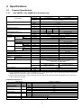
2 Specifications
2.1.
Product Specification
2.1.1.
CS-F28DTE5 CU-L50DBE5 (For Australia only)
ITEM / MODEL
Cooling Capacity
Heating Capacity
Refrigerant Charge-less
Standard Air Volume for High,
Medium and Low Speed
Outside Dimension (H x W x D)
Net Weight
Piping
Connection
Refrigerant
Indoor Unit
CS-F28DTE5 x 2
Main Body
Remote
Control
kW
BTU/h
kW
BTU/h
m
Gas
Liquid
Drain
Type, Number of Set
Starting Method
Type
Motor
Rated Output
Fan
Type, Number of Set
Type
Motor
Rated Output
Air-heat Exchanger (Row x Stage x FPI)
Refrigerant Control
m3/min
cfm
mm
inch
kg (lbs)
mm (inch)
mm (inch)
mm
Compressor
Refrigerant Oil (Charged)
Refrigerant (Charged) R410A
Control Switch
Running
Adjustment
Room Temperature
Safety Devices
Noise Level
kW
kW
cm3
kg (oz)
dB (A)
Power level dB
Moisture Removal
EER
COP
L/h (Pt/h)
W/W
W/W
Outdoor Unit
CU-L50DBE5
CZ-RD513C (Wired)
CZ-RL513T (Wireless)
14.0
47,700
16.0
54,600
30
Hi 18 x 2
Me 16
Lo 14
Hi 98
636 x 2
565
495
3460
210 x 1245 x 700
1340 x 900 x 320
8-9/32 x 49-1/64 x 27-9/16
52-7/8 x 35-7/16 x 12-19/32
33 (73)
110 (242)
O.D Ø 15.88 (5/8) Flared Type
O.D Ø 9.53 (3/8) Flared Type
O.D Ø 20
I.D Ø 20 x 1
Hermetic - 2P (Rotary), 1
DC - INV control
4-pole single phase brushless motor
3.8
Sirocco fan-4
Mix flow fan - 1
4-pole single phase induction motor
6-pole single phase induction motor
0.04 x 2
0.07 x 2
Slit-fin type (2 x 12 x 18)
Corrugate-fin type (2 x 51 x 18)
Exp. Valve
-
FV50S (1200)
3.50 (123)
Wireless or Wired Remote Control
Thermostat
Temperature, current and pressure protection control for compressor,
Internal thermostat for FM, High pressure switch,
Current trans, Crankcase heater
Hi 45 Lo 41
Cooling 55, Heating 57
Cooling : Hi 62 Lo 58
Cooling 69, Heating 71
Heating : Hi 62 Lo 58
9.0 (19.0)
2.91
3.34
1. Cooling capacities are based on indoor temperature of 27°C D.B. (80.6°F D.B.), 19.0°C W.B. (66.2°F W.B.) and outdoor air
temperature of 35°C D.B. (95°F D.B.), 24°C W.B. (75.2°F W.B.)
2. Heating capacities are based on indoor temperature of 20°C D.B. (68°F D.B.) and outdoor air temperature of 7°C D.B. (44.6°F
D.B.), 6°C W.B. (42.8°F W.B.)
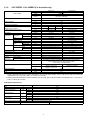
ELECTRICAL DATA (50 Hz)
ITEM / MODEL
Volts
V
Phase
Power Consumption
kW
Condition by JIS-B8615
240
Single
Cool
4.81
Heat
4.79
Running Current
A
Cool
21.0
Heat
20.9
Starting Current
A
21.0
Power Factor
%
Cool
95
Heat
95
*Power Factor means total figure of compressor, indoor fan motor and outdoor fan motor.
Panasonic
Power source
AC, 1~240V 50Hz
3
2.1.2.
CS-F50DTE5 CU-L50DBE5 (For Australia only)
ITEM / MODEL
Cooling Capacity
Heating Capacity
Refrigerant Charge-less
Standard Air Volume for High,
Medium and Low Speed
Outside Dimension (H x W x D)
Net Weight
Piping
Connection
Refrigerant
Indoor Unit
CS-F50DTE5
Main Body
Panel
Remote
Control
kW
BTU/h
kW
BTU/h
m
Gas
Liquid
Drain
Type, Number of Set
Starting Method
Type
Motor
Rated Output
Fan
Type, Number of Set
Type
Motor
Rated Output
Air-heat Exchanger (Row x Stage x FPI)
Refrigerant Control
m3/min
cfm
mm
inch
kg (lbs)
mm (inch)
mm (inch)
mm
Compressor
Refrigerant Oil (Charged)
Refrigerant (Charged) R410A
Control Switch
Running
Adjustment
Room Temperature
Safety Devices
Noise Level
kW
kW
cm3
kg (oz)
dB (A)
Power level dB
Moisture Removal
EER
COP
L/h
W/W
W/W
Outdoor Unit
CU-L50DBE5
CZ-BT03P
CZ-RD513C (Wired)
CZ-RL513T (Wireless)
14.0
47,700
16.0
54,600
30
Hi 32
Me 28
Lo 26
Hi 98
1130
1040
960
3460
250 x 1600 x 700
1340 x 900 x 320
9-27/32 x 62-31/32 x 27-9/16
52-7/8 x 35-7/16 x 12-19/32
47 (104)
105 (231)
O.D Ø 15.88 (5/8) Flared Type
O.D Ø 9.53 (3/8) Flared Type
O.D Ø 20
I.D Ø 20 x 1
Hermetic - 2P (Rotary), 1
DC - INV control
4-pole single phase brushless motor
3.8
Sirocco fan-4
Mix flow fan - 2
4-pole single phase induction motor
6-pole single phase induction motor
0.14
0.07 x 2
Slit-fin type (3 x 14 x 18)
Corrugate-fin type (2 x 51 x 18)
Exp. Valve
-
FV50S (1200)
3.50 (123)
Wireless or Wired Remote Control
Thermostat
Temperature, current and pressure protection control for compressor,
Internal thermostat for FM, High pressure switch,
Current trans, Crankcase heater
Hi 50 Lo 46
Cooling 55, Heating 57
Cooling : Hi 67 Lo 63
Cooling 69, Heating 71
Heating : Hi 67 Lo 63
9.0
2.91
3.34
1. Cooling capacities are based on indoor temperature of 27°C D.B. (80.6°F D.B.), 19.0°C W.B. (66.2°F W.B.) and outdoor air
temperature of 35°C D.B. (95°F D.B.), 24°C W.B. (75.2°F W.B.)
2. Heating capacities are based on indoor temperature of 20°C D.B. (68°F D.B.) and outdoor air temperature of 7°C D.B. (44.6°F
D.B.), 6°C W.B. (42.8°F W.B.)
ELECTRICAL DATA (50 Hz)
ITEM / MODEL
Volts
V
Phase
Power Consumption
kW
Condition by JIS-B8615
240
Single
Cool
4.81
Heat
4.79
Running Current
A
Cool
21.0
Heat
20.9
Starting Current
A
21.0
Power Factor
%
Cool
95
Heat
95
*Power Factor means total figure of compressor, indoor fan motor and outdoor fan motor.
Panasonic
Power source
AC, 1~240V 50Hz
4
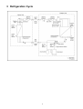
3 Refrigeration Cycle
5
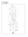
4 Block Diagram
4.1.
CU-L50DBE5
6
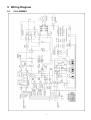
5 Wiring Diagram
5.1.
CU-L50DBE5
7
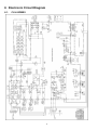
6 Electronic Circuit Diagram
6.1.
CU-L50DBE5
8
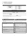
7 Installation Instruction
7.1.
Outdoor Unit Installation
AIR CONDITIONERS OUTDOOR UNIT INSTALLATION INSTRUCTIONS
Precautions in terms of safety
Carry out installation work with reliability after through reading of this “Precautions in terms of safety”.
• Precautions shown here are differentiated between
and
. Those that have much chances for
leading to significant result such as fatality or serious injury if wrong installation would have been carried out are listed compiling
them especially into the column of
.
However, even in the case of items which are listed in the column of
, such items also have a chance for leading
to significant result depending on the situations.
In either case, important descriptions regarding the safety are listed, then observe them without fail.
• As to indications with illustration
This mark means “Caution” or “Warning”.
This mark means “Earth”.
• After installation work has been completed, do not only make sure that the unit is free from any abnormal condition through the
execution of trial run but also explain how to use and how to perform maintenance of this unit to the customer according to the
instruction manual.
• In addition, request the customer to keep this manual for installation work together with instruction manual.
▲ The appliance must be installed by technician, who takes into
account the requirements given by ISO5149 or eventual
equivalent requirements.
▲ As to installation, request the distributor or vendor to perform it.
Imperfection in installation caused by that having been carried
out by the customer himself may leads to water leakage, electric
shock, fire, etc.
▲ Carry out the installation work with reliability according to this
manual for installation work.
Imperfection in installation leads to water leakage, electric
shock, fire, etc.
▲ Carry out the installation work with reliability on the place that
can bear the weight of this unit sufficiently. Insufficient strength
leads to injury due to falling of the unit.
Warnings
▲ If installing inside a small room, measures should be taken to
prevent refrigerant levels from building up to critical
concentrations in the event of a refrigerant leak occurring.
Please discuss with the place of purchase for advice on what
measures may be necessary to prevent critical concentrations
being exceeded. If the refrigerant leaks and reaches critical
concentration levels, there is the danger that death from
suffocation may result.
▲ Securely attach the protective covers for the outdoor unit
connection cables and power cord so that they do not lift up
after installation. If the covers are not properly attached and
installed, the terminal connections may overheat, and fire or
electric shock may result.
▲ Switch off all supplies before accessing any electrical part.
▲ If refrigerant gas escapes during installation, ventilate the
affected area. If the refrigerant gas comes into contact with
sparks or naked flames, it will cause toxic gases to be
generated.
9
▲ The unit must be installed in accordance with applicable national
and local regulations. Any electrical work should only be carried
out by qualified technician and use exclusive circuits without fail.
Presence of insufficient capacity in power circuit or imperfection
in execution leads to electric shock, fire, etc.
▲ Wiring shall be connected securely using specified cables and
fix them securely so that external force of the cables may not
transfer to the terminal connection section.
Imperfect connection and fixing leads to fire, etc.
▲ Do not install the unit at the place where the possibility of
inflammable gas leakage exists. If such gas leakages should
arise and the gas builds up around the unit, such situation may
lead to ignition.
7.1.1.
Warnings
▲ When performing piping work do not mix air except for specified
refrigerant (R410A) in refrigeration cycle. It causes capacity
down, and risk of explosion and injury due to high tension inside
the refrigerant cycle.
▲ Earth
This equipment must be properly earthed. Earth
line must not be connected to gas pipe, water
pipe, lightning rod and telephone. Otherwise, it
may cause electrical shock in case the
equipment breakdown or has leakage current.
▲ Installation of Earth Leakage Current Breaker
This equipment must be installed with earth leakage current
breaker.
Otherwise, it may cause electrical shock and fire in case the
equipment breakdown or has leakage current.
Cautions
▲ Drain piping should be made to ensure secure drainage
according to the manual for installation work and carry out the
thermal insulation to prevent the occurrence of condensation.
Imperfection in piping work leads to water leakage and may
cause the house and property, etc. to become wet.
▲ Position the indoor unit and outdoor unit, power cords and
indoor/outdoor unit connection cables in a way so that they are at
least 1 meter away from televisions and radios.
This is to avoid problem such as interference with picture and/or
sound. (However, note that depending on the electromagnetic
wave conditions, interference may still occur even if the
separation distance is more than 1 meter.)
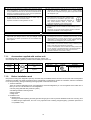
Accessories supplied with outdoor unit
• The following parts are supplied as accessories with each outdoor unit.
Check that all accessory parts are present before installing the outdoor unit.
Part name
Protective
bushing
Q’ty
2
Banding
strap
3
7.1.2.
Diagram
Application
For protecting electrical
wires
Part name
Drain elbow AS
For tying electrical wires
together
Heat pump-types only
Q’ty
Diagram
Application
1
For connecting the drain
pipe (with ring seat)
Before installation work
• This product is using new refrigeration (R410A). The basic way of installation work is the same as usual, but water and impurities
should be controlled more strictly than before due to characteristic of refrigerating machine oil. Therefore, selection of materials
to use and processing, storing and brazing need appropriate construction and control.
1. Tools and materials
There are tools and materials for both new refrigeration and usual refrigeration you can use together and for either two of
them you can use. Use the below for new refrigeration.
• Vacuum pump (with back flow preventor system)
• Gas leakage detection warning device
• Gauge manifold
• Charge hose
2. Installation work
a. Brazing work
Brazing work needs replacing air inside pipe with nitrogen gas in order to prevent oxidization scale from occurring. This
is called nitrogen replacement, and one of very important work in brazing refrigerant piping. (Oxidation preventive is
not possible to use)
10
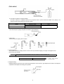
b. Prevention measure for refrigerant piping
Prevention measure for refrigerant piping is very important work to prevent water-dust-rubbish from getting in. All
piping terminals needs sealing such as shown below.
Place
Outside
Period of work
More than 1 month
Less than 1 month
Not specified
Inside
Method of seal
Pinch
Pinch or taping
• How to pinch
Close terminal part of piping with pliers and seal the gap with brazing.
• How to tape
Seal terminal part of piping with vinyl tape.
3. Vacuum pumping
The purpose of vacuum pumping work is to remove and dry air inside the piping or nitrogen at air tightness test.
Perform the work carefully.
Caution
Use the vacuum pump with the backflow prevention mechanism to prevent backflow of oil.
Vacuuming time
60 minutes or more
Vacuum pump capacity
60 l/min or more
4. Refrigerant filling
Refrigerant filling must be done in the state of liquid refrigerant. If this is done in gas refrigerant, the balance of refrigerant
composition will collapse and damage the operation.
11
For the use of a gas cylinder without siphon inside, turn it upside down and use it.
(We recommend manifold with sight glass.)
Caution
Do not use a “CHARGE CYLINDER”.
Caution
As a rule, please collect all existing refrigerants in the system outside the system when the refrigerant leakage occurs by the
system.
After that, please fill new refrigerant of a regulated amount again.
DRY VACUUMING
• If vacuum pump possible vacuuming until less than -100.7kpa.
1. Running vacuum pump at both liquid and gas side for more than 1 hour and vacuuming until -100.7kpa.
2. After that keep the pressure -100.7kpa for 1 hour and confirm the vacuum gauge value not increasing.
3. If vacuum gauge value is increase, there is possibility of water inside the unit or there is any leakage.
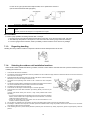
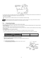
7.1.3.
Regarding handling
Handling the unit by hold the handle at compressor side and hold the basepan bottom at fan side.
7.1.4.
Selecting the outdoor unit installation locations
• Select location which satisfies the following condition, and then confirm with the customer that such a place is satisfactory before
installing the outdoor unit.
1.
2.
There should be sufficient ventilation.
The outdoor unit should be sheltered as much as possible from rain and direct sunlight, and the air should be able to move around so that hot
and cold air do not build up.
3. There should not be animals or plants near the air outlet which could be adversely
affected by hot or cold air coming out from the unit.
4. The outlet air and operating noise should not be a nuisance to other occupants
nearby.
5. The location should be able to withstand the full weight and vibration of the outdoor
unit, and it should also be level and safe for the unit to be installed.
6. The intake and outlet should not be covered.
7. There should not be danger of flammable gas or corrosive gas leaks.
8. There should be as little back-ventilation (air blowing directly onto the fan) as
possible.
(If strong wind blows directly onto the fan, it may cause problems with normal
operation.)
• If you know which direction the prevailing wind comes from during the operating
season, set the outdoor unit at a right-angle to this wind direction, or so that air
outlet faces toward a wall or fence.
• If there are obstructions near the outdoor unit and the wind direction is not
constant, install an optional air guider.
9. Do not allow any obstacles near the outdoor unit which will interfere with air flow around the air intake and air outlet.
10. If installing in a location which is prone to snowfall, place the installation base as high as possible, and be sure to install a roof or enclosure
which does not allow snow to accumulate.
11. Avoid installing the unit in places where petroleum products (such as machine oil), salinity, sulphurous, gases or high-frequency noise are
present.
12
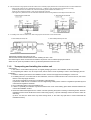
12. Be sure to leave enough space around the outdoor unit to maintain proper performance and to allow access for routine maintenance.
• Allow enough space from any obstacles as shown in Fig. 1.2 below in order to prevent short-circuits from occurring.
(If installing more than one outdoor unit, make the necessary space available as outlined in 13.)
However, there should be at least 1 meter of free space above the unit.
• The height of any obstacles at the air intake and outlet sides should not be greater than the height of the outdoor unit.
13. If installing more than one outdoor unit, allow enough space around each unit as shown below.
Maintain sufficient space above the unit.
Values inside brackets indicate distances when installing the 4HP - 6HP.
• The distance given above are the minimum distance required in order to maintain proper performance.
Allow as much space as possible in order to get the best performance from the units.
7.1.5.
Transporting and installing the outdoor unit
• Transporting
1. The outdoor unit should be transported in its original packaging as close to the installation location as possible.
2. If suspending the outdoor unit, use a rope or belt, and use cloth or wood as padding in order to avoid damaging the unit.
• Installation
1. Read the “Selecting the outdoor unit installation location” section thoroughly before installing the outdoor unit.
2. If installing the unit to a concrete base or other solid base, use M10 or W3/8 bolts and nuts to secure the unit, and ensure
that the unit is fully upright and level.
(The anchor bolt positions are shown in the diagram at the right side.)
In particular, install the unit at a distance from the neighbouring building which conforms to regulations specified by local
noise emission regulation standards.
3. Do not install the outdoor unit to the building’s roof.
4. If there is a possibility that vibration may be transmitted to the rooms of the building, place rubber insulation between the
unit and the installation surface.
5. Drain water will be discharged from the outdoor unit when operating the system in heating or defrosting modes. Select an
installation location which will allow the water to drain away properly, or provide a drainage channel so that the water can
drain away.
(If this is not done, the drain water may freeze during winter, or the water may spill down to areas underneath the
installation location.)
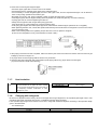
13
• If a drain pipe needs to be installed, insert the accessory drain elbow into the mounting hole at the bottom of the outdoor unit,
and connect a hose with an inside diameter of 15mm to this drain elbow.
(The hose is not supplied.)
If using the drain elbow, install the outdoor unit on a base which is at least 5cm high.
NOTE
7.1.6.
In cold regions (where the outdoor air temperature can drop to 0°C or below continuously for 2-3 days), the drain water may freeze,
and this may prevent the fan from operating. Do not use the drain elbow in such cases.
Connecting the pipes
• Use a clean pipe which does not include water or dust for inside of piping.
• When cutting the refrigerant pipes, a piping cutter must be used. Before connecting the refrigerant pipes, blow nitrogen and blow
off dust in the pipes.
(Never use tools which cause a lot of dust such as a saw and a magnet.)
• When waxing replace nitrogen inside the piping after removing dirt and dust. (In order to prevent oxidation scale from forming
inside the piping).
• The refrigerant pipes are of particular importance.
The installation work for refrigerant cycles in separate-type air conditioners must be carried out perfectly.
1. Refer to the table below for the pipe diameters equivalent lengths and indoor/outdoor unit difference of elevation.
Pipe diameter (mm)
Liquid-side pipes
Gas-side pipes
ø9.53 x 0.8
ø15.88 x 1.0
Equivalent length (m)
Difference of elevation (m)
50
30
2. Local pipes can project in any of four directions.
• Make holes in the pipe panels for the pipes to pass through.
• Be sure to install the pipe panels to prevent rain from getting inside the outdoor unit.
[Removing the service panel].
(1)
(2)
Remove the two mounting screws.
Slide the service panel downward to release the pawls. After this, pull the
service panel toward you to remove it.
14
3. Notes when connecting the refrigerant pipes.
• Use clean copper, pipes with no water or dust on the insides.
• Use phosphorus-free, unjointed copper pipes for the refrigerant pipes.
• If it is necessary to cut the refrigerant pipes, be sure to use a pipe cutter, and use compressed nitrogen or an air blower to
clean out any foreign particles from inside the pipe.
• Be careful not to let any dust, foreign materials or water get inside the pipes during connection.
• If bending the pipes, allow as large a bending radius as possible. Do not flex the pipes any more than necessary.
• If joining pipe ends, do so before tightening the flare nut.
• Always blow the pipe end with nitrogen while joining pipe ends.
(This will prevent any oxide scaling from occurring inside the pipe.)
• If using long pipe lengths with several joined pipe ends, insert strainers inside the pipes. (Strainers are not supplied.)
• When tightening the flare nuts, coat the flare (both inside surfaces) with a small amount of refrigerator oil, and screw in about
3-4 turns at first by hand.
• Refer to the following table for the tightening torques. Be sure to use two spanners to tighten.
(If the nuts are overtightened, it may cause the flares to break or leak.)
4. After piping connection has been completed, make sure that the joint areas of the indoor and outdoor units are free from gas
leakage by the use of nitrogen, etc.
5. Air purge within connection piping shall be carried out by evacuation.
6. Close the tube joining area with putty heat insulator (local supply) without any gap as shown in below figure.
(To prevent insects or small animal entering)
7.1.7.
Heat insulation
Liquid-side pipes
Gas-side pipes
Caution Use a material with good heat-resistant properties as
the heat insulation for the pipes. Be sure to insulate
both the gas-side and liquid-side pipes. If the pipes are
not adequately insulated, condensation or water
leakages may occur.
7.1.8.
Material that can withstand
120°C or higher
Charging with refrigerant
• At the time of shipment from the factory, this unit is charged with enough refrigerant for an equivalent pipe length of 30m. If the
equivalent pipe length used will be 30m or less, no additional charging will be necessary.
• If the equivalent pipe length will be between 30 and 50m, charge with additional refrigerant according to the equivalent length
given in the table below.
- For standard type
Additional charging amount
0.05 kg/m
Equivalent length
50m
15
• Pump down operation
- Operate the pump down according to the following procedures.
Procedure
1. Confirm the valve on the liquid side and the gas side is surely open.
2. Press the PUMP DOWN switch on outdoor printed board for 1
second or more.
3. Shut the valve on the liquid side surely.
7.1.9.
Notes
Perform the cooling operation for five minutes or more.
When the valve is shut halfway, the compressor is occasionally
damaged.
Electrical wiring
Warning
Warning
Warning
Warning
The units must be connected to the supply cables for fixed wiring by qualified technician.
Feed the power source to the unit via a distribution switch board designed for this purpose, the switch should disconnected all
poles with a contact separation of at least 3mm.
When the supply cable is damaged, it must be replaced by qualified technician.
Be sure to install a current leakage breaker, main switch and fuse to the main power supply, otherwise electric shocks may
result.
Be sure to connect the unit to secure earth connection.
If the earthing work is not carried out properly, electric shocks may result.
Wiring shall be connected securely by using specified cables and fix them securely so that external force of the cables may not
transfer to the terminal connection section.
Imperfect connection and fixing leads to fire, etc.
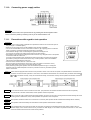
• Connect the power supply wiring and indoor/outdoor unit connection wiring according to the electrical circuit diagram
instructions.
• Clamp the wires securely to the terminal connections using cord clamps so that no undue force is placed on the wires.
• Once all wiring work has been completed, tie the wires and cords together with the binding strap so that they do not touch other
parts such as the compressor and pipes.
1.
2.
3.
4.
5.
6.
7.
Connect the power supply line to a 3-phase/380-415V (or single-phase 220-240V)
power supply.
The equipment shall be connected to a suitable mains network with a main
impedance less than the valve indicated in the table of power supply specifications.
Be sure to connect the wires correctly to terminal board with connecting the crimp
type ring terminal to the wires.
The binding screws inside the power supply box may become loosened due to
vibration during transportation, so check that they are tightened securely.
Tighten the binding screws to the specified torque while referring to the table
below.
If connecting two separate wires to a single crimped terminal, place the two
crimped terminal wires together as shown in Fig. A. (If the arrangement shown in
Fig. B is used, poor contacts or contact damage may result.)
If momentarily turning on the power supply for both the indoor and outdoor units,
do not turn the power off again until at least 1 minute has passed (except when a
reversed phase has been detected).
Warning
Use only the specified cables for wiring connections. Connect the cable securely, and secure them properly so that no undue
force will be applied to the terminal connections.
If the terminals are loose or if the wires are not connected securely, fire may result.
Terminal screw
M3
M4
M5
Tightening torque N.cm {kgf.cm}
69 ~ 98 {7 ~ 10}
157 ~ 196 {16 ~ 20}
196 ~ 245 {20 ~ 25}
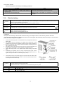
16
Earth lead wire shall be longer than other lead wires as shown in the figure for the electrical safety in case of the slipping out of the
cord from the anchorage.
• Power supply specifications
Model name
CU-L24DB***
CU-L28DB***
CU-L34DB***
CU-L43DB***
CU-L50DBE5
220V-240V~
220V-240V~
220V-240V~
220V-240V~
240V~
Leakage
current
breaker
(A)
30
30
40
40
40
Circuit breaker
(Minimum Capacity)
Switch
Fuse
(A)
(A)
30
30
40
40
40
Minimum
power
supply
cables
4mm2
cable
based on
length (m)
Maximum
permissible
impedance
(Ω)
4mm2
14
14
9
8
8
0.1
0.1
0.05
0.05
20
20
30
40
40
Indoor/outdoor
unit connection
power cables
(terminals
,
,
,
)
2.5 mm2 x 4
NOTE
1. Where ground work (earth) is carried out, do not connect the ground return to the gas pipe, water line pipe, grounded circuit of the
telephone and lightning rod, or ground circuit of other product in which earth leakage breaker is incorporated. (Such action is
prohibited by statute, etc.)
Make sure the indoor and outdoor connection wires are detangled. (There might be effect to received outside noise.)
2. Use the standard power supply cables for Europe (such as H05RN-F or H07RN-F which conforms to CENELEC (HAR) rating
specifications) or use the cables based on IEC standard. (245IEC57, 245IEC66)
3. Select the particular size of electrical wire for power supply cables in accordance with the standards of the given nation and
region.
17
7.1.10. Connecting power supply cables
CAUTION
• For three phase model, never operate the unit by pressing the electromagnetic switch.
• Never correct the phase by switching over any of the wires inside the unit.
7.1.11.
Precautions with regard to test operation
CAUTION
• Always be sure to use a properly-insulated tool to operate the switch on the circuit board. (Do not
use your finger or a metallic object.)
• Never turn on the power supply until all installation work has been completed.
• Turn on the circuit breaker 12 hours or more before a test run. (By supplying power to crankcase
heater, compressor is warmed and liquid compressing is prevented.)
• Check that the voltage is 90% of rated voltage or higher when starting the unit.
(The unit will not operate if the voltage is less than 90% of rated voltage.)
• Test operation can be carried out using the remote control unit or by using the switch on the printed
circuit board inside the outdoor unit.
If carrying out test operation at the printed circuit board of the outdoor unit, follow the procedure
given below. (If using the remote control unit to carry out test operation, refer to the installation
manual which is supplied with the indoor unit.)
• Press the COOL or HEAT switch for 1 second or more.
(Be sure to select cooling mode first, and run the units in this mode for 5 minutes or more.)
• Press the TEST button once more to cancel test operation mode.
• When performing heating test operation when the outside temperature is high, or cooling test
operation when the outside temperature is low, the protection circuits may sometimes operate
within a few minutes.
NOTE 1
These units are equipped with connection error prevention circuits. If the units do not operate, it is possible that the connection error
prevention circuits have been operated. In such cases, check that the Indoor/outdoor unit connection wire (connected to terminals
and
,
) is connected correctly. If they are connected incorrectly, connect them correctly. Normal operation should then commence.
NOTE 2
Do not short the remote control unit wires to each other. (The protection circuit will be activated and the units will not operate.)
Once the cause of the short is eliminated, normal operation will then be possible.
NOTE 3
When running the units in heating mode during test operation, be sure to run the units in cooling mode first before selecting this mode.
If heating mode is selected first, it may cause problems with operation of the compressor.
NOTE 4
Test operation should be carried out for a minimum of 5 minutes. (Test operation will be cancelled automatically after 30 minutes.)
NOTE 4
Test operation mode should always be cancelled once test operation itself has been completed.
NOTE
If the self-diagnosis function reports a problem but more than one problem has developed at the indoor and/or outdoor units, the
problem display on the remote control unit may not match the LED display on the outdoor unit printed circuit board. In such cases,
check both locations and remove the causes of the problems.
18
7.1.12. As to making the inspection after completion of work fully understood
• At the time when the work has been completed, measure and record the characteristics of test run without fail and keep the measuring date, etc.
• Carry out the measurement regarding room temperature, outside air temperature, suction and air discharge temperatures, wind
velocity, wind volume, voltage current, presence of abnormal vibration, operating pressure, piping temperature, compressive
pressure, airtight pressure as items to be measured.
• As to the structure and appearance, check following items.
Short circuit of the blow-out air
Mistake in wiring
Smooth flow of the drain
Reliable connection of the grand wire
Reliable thermal insulation
Looseness in terminal screw, fastening torque
M3... 69-98N.cm {7-10kgf.cm} M4... 157-196N.cm {16-20kgf.cm}
M5... 196-245N.cm {20-25kgf.cm}
Leakage of refrigerant
7.1.13. As to delivery to the customer
• Request the customer to operate this air conditioner viewing instruction manual come with indoor unit in practice and explain
how to operate.
• Deliver the instruction manual to the customer without fail.
19
8 Technical Data
8.1.
Sound Data
20
8.2.
Capacity And Power Consumption
8.2.1.
Cooling performance
Model name
CS-F24DTE5 / CU-L24DBE5
CS-F28DTE5 / CU-L28DBE5
CS-F34DTE5 / CU-L34DBE5
CS-F43DTE5 / CU-L43DBE5
CS-F50DTE5 / CU-L50DBE5
Max cooling capacity
Max capacity (kw)
Max power consumption (kw)
6.5
2.3
7.5
2.45
12
3.4
13.5
4.3
16
5.1
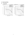
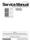
Calculation of actual cooling capacity and power consumption:
Example: CS-F24DTE5 / CU-L24DBE5
• Calculation of the actual cooling capacity and power consumption for the following cooling conditions;
Indoor temperature of 27/19°C and outdoor temperature of 40°C (Standard condition).
Calculation method
1. Find the cooling capacity ratio and the power consumption ratio from the cooling capacity graph and power consumption graph for model CSF24DTE5 / CU-L24DBE5.
• The cooling capacity ratio indicate at the intersection between an outdoor unit air inlet temperature of 40°C on the horizontal axis and an
indoor unit air inlet temperature on 27/19°C is 0.95.
• The cooling power consumption ratio from the same intersection on the power consumption graph is 1.03.
2. Thus,
• Actual cooling capacity = cooling capacity ratio x rated cooling capacity = 0.95 x 6.5 = 6.18 (kw).
• Actual cooling power consumption = cooling power consumption x rated power consumption = 1.03 x 2.45 = 2.52 (kw).
21
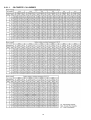
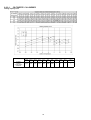
8.2.1.1.
CS-F50DTE5 CU-L50DBE5
22
Cooling capacity curve
23
Cooling power consumption curve
24
8.2.2.
Heating performance
Model name
CS-F24DTE5 / CU-L24DBE5
CS-F28DTE5 / CU-L28DBE5
CS-F34DTE5 / CU-L34DBE5
CS-F43DTE5 / CU-L43DBE5
CS-F50DTE5 / CU-L50DBE5
Max heating capacity
Max capacity (kw)
Max power consumption (kw)
7.5
3.15
8.5
3.25
13.5
4.20
15.5
5.00
18
6.00
1. Heating capacity when the unit is frosted over or while being defrosted will vary depending on outdoor temperature and the
frosting.
2. Heating capacity must be compensated because it does not take into account the capacity drop incurred when the unit is
frosted over and while it is being defrosted.
3. Therefore, to obtain the integral heating capacity in consideration overfrosting and defrost operations.
4. Heating capacity must be multiplied by the compensation coefficient below.
25
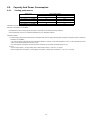
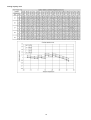
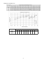
8.2.2.1.
CS-F50DTE5 CU-L50DBE5
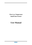
Heating capacity curve
Outdoor intake air ambient temperature (D.B./ °C)
-20°C -15°C -10°C -5°C
0°C
2°C
5°C
7°C
10°C 15°C
Heating
capacity
compensation
coefficient
0.93
0.93
0.93
0.92
0.84
26
0.88
0.96
1
1
1
>15°C
1
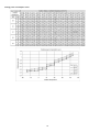
Heating power consumption curve
Outdoor intake air ambient temperature (D.B./ °C)
-20°C -15°C -10°C -5°C
0°C
5°C
7°C
10°C 15°C
Heating
capacity
compensation
coefficient
0.93
0.93
0.93
0.92
27
0.86
0.97
1
1
1
>15°C
1
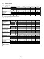
8.3.
8.3.1.
Safety device
Indoor unit
Indoor unit
Heat pump model
Cooling only model
For fan motor protection
Internal
protector
For condensation temperature
protection control
Heat exchanger
thermistor
For P.C.B current protection
Current fuse
CS-F24DTE5
CS-F28DTE5
CS-F34DTE5
CS-F43DTE5
CS-F50DTE5
OFF
ON
°C
°C
135
87
135
87
135
86
135
86
135
86
OFF
RESET
°C
°C
58
54
58
54
58
54
58
54
58
54
CUT
A
3.15
3.15
3.15
3.15
3.15
Note : Protection controlled by P.C.B installed of FM inside.
8.3.2.
Outdoor unit
Outdoor unit
Heat pump
model
50Hz
CU-L24DBE5
CU-L28DBE5
CU-L34DBE5
CU-L43DBE5
CU-L50DBE5
For refrigerant cycle
High pressure
OFF
MPa
4.2
4.2
4.2
4.2
4.15
switch
ON
MPa
3.3
3.3
3.3
3.3
3.3
OFF
RESET
OFF
A
A
A
12
8
16
12.6
9
17
17
13
22
20
15
25
22.5
17.5
27.5
OFF
RESET
OFF
A
A
A
14.6
8
18
14.6
9
19
23
13
28
25
15
30
25.2
17.5
30
Compressor
°C
For compressor over current
protection for cooling mode
CT1 frequency down
CT2 compressor stop
For compressor over current
protection for heating mode
CT1 frequency down
CT2 compressor stop
Discharge temp protection
Discharge temperature
thermistor (Td)
Liquid compress protection
Crankcase heater
For fan motor protection
Internal
protector (49F)
For condensation temperature
protection control
Heat exchanger
thermistor (Th)
For control protection
Fuse
Td
OFF
Td
110°C → Comp OFF
110°C x 3 times within 1 hour → display error cord
-
W
33
33
33
33
33
OFF
ON
°C
°C
135
87
135
87
135
87
135
87
135
87
OFF
RESET
°C
°C
58
54
58
54
58
54
58
54
58
54
CUT
A
6.3
6.3
6.3
6.3
6.3
1MPa = 10.2kgf/cm2
28
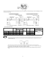
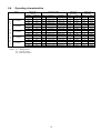
8.4.
Operating characteristics
Model
H
E
A
T
P
U
M
P
M
O
D
E
L
CS-F24DTE5
CU-L24DBE5
CS-F28DTE5
CU-L28DBE5
CS-F34DTE5
CU-L34DBE5
CS-F43DTE5
CU-L43DBE5
CS-F50DTE5
CU-L50DBE5
Legend :
Main Power
Source
Voltage
Frequency
(V)
(Hz)
220
50
230
50
240
50
220
50
230
50
240
50
220
50
230
50
240
50
220
50
230
50
240
50
220
230
240
50
Compressor Motor
S.C.
(A)
9.9
9.5
9.2
11.1
10.7
10.3
14.4
13.9
13.5
19.5
18.8
18.2
20.8
R.C. (A)
COOL / HEAT
7.28 / 7.98
6.98 / 7.68
6.78 / 7.38
8.8 / 9.2
8.5 / 8.9
8.1 / 8.5
10.7 / 12.2
10.3 / 11.8
10.0 / 11.3
15.5 / 16.6
15.0 / 16.1
14.5 / 15.6
19.14 / 19.54
S.C. : Starting Current
R.C. : Running Current
IPT : Power Consumption
29
IPT (kW)
COOL / HEAT
1.55 / 1.69
1.55 / 1.69
1.55 / 1.69
1.85 / 1.96
1.85 / 1.96
1.85 / 1.96
2.29 / 2.60
2.29 / 2.60
2.29 / 2.60
3.31 / 3.55
3.31 / 3.55
3.31 / 3.55
4.31 / 4.41
Indoor Unit
Fan Motor
R.C.
IPT
(A)
(kW)
0.17
0.03
0.17
0.03
0.17
0.03
0.20
0.035
0.20
0.035
0.20
0.035
0.35
0.07
0.35
0.07
0.35
0.07
0.45
0.09
0.45
0.09
0.45
0.09
2.67
0.10
Outdoor Unit
Fan Motor
R.C.
IPT
(A)
(kW)
0.55
0.12
0.55
0.12
0.55
0.12
0.55
0.12
0.55
0.12
0.55
0.12
1.10
0.24
1.10
0.24
1.10
0.24
1.10
0.24
1.10
0.24
1.10
0.24
1.10
0.24
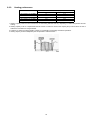
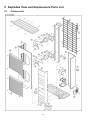
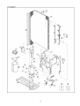
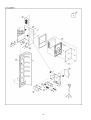
9 Exploded View and Replacement Parts List
9.1.
Outdoor Unit
30
31
32
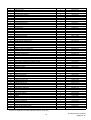
NO.
1
2
3
4
4a
5
6
7
8
9
10
11
12
13
15
17
19
20
21
22
23
24
25
26
27
28
29
31
32
33
34
36
38
44
46
48
49
50
50a
54
54a
55
56
57
58
59
60
61
62
63
64
65
66
67
68
69
70
71
72
73
74
PART DESCRIPTION
BASE PAN ASS’Y
COMPRESSOR
ANTI-VIBRATION BUSHING
NUT FOR COMP. MOUNT.
PACKING
CRANKCASE HEATER
CONDENSER COMPLETE
TUBE ASS’Y(PRESSURE SWITCH)
DISCHARGE MUFFLER
HIGH PRESSURE SWITCH
3-WAYS VALVE (GAS)
4-WAYS VALVE
3-WAYS VALVE (LIQUID)
STRAINER
PIPE HOLDER RUBBER
HOLDER-SERVICE VALVE
ACCUMULATOR ASS’Y
SOUND PROOF MATERIAL-COMP
SOUND PROOF MATERIAL
SOUND-PROOF BOARD ASS’Y
V-COIL COMPLETE
V-COIL COMPLETE
SENSOR-OD TEMP./COIL
SENSOR-COMP.DISCHARGE
SENSOR-COMP.SUCT/DEFROST
CABINET REAR PLATE
CONTROL BOARD ASS’Y
TERMINAL BOARD ASS’Y
TERMINAL BOARD ASS’Y
CAPACITOR-FAN MOTOR (3/460)
ELECTRONIC CONTROLLER (P. SUPPLY)
ELECTRONIC CONTROLLER (DISPLAY)
ELECTRONIC CONTROLLER (NOISE FILTER)
ELECTRONIC CONTROLLER (MAIN)
REACTOR
TERMINAL COVER
NUT FOR TERMINAL COVER
BRACKET FAN MOTOR
SCREW-BRACKET FAN MOTOR
FAN MOTOR
SCREW-FAN MOTOR
PROPELLER FAN
NUT for PROPELLER FAN
CABINET FRONT PLATE
DISCHARGE GRILLE
CABINET SIDE PLATE
WIRE NET
CABINET TOP PLATE COMPLETE
ACCESSORY COMPLETE
BAG-COMPLETE (L-TUBE)
PIPE COVER (FRONT)
PIPE COVER (BACK)
CABINET FRONT PLATE COMPLETE
HANDLE
TUBE ASS’Y (CAPILLARY TUBE)
MAGNETIC SWITCH
SPRING FOR SENSOR
4-WAYS VALVE COMPLETE
CONDENSER SIDE PLATE
INSTALLATION INSTRUCTION
EXPANSION VALVE
QTY
1
1
3
3
3
1
1
1
1
1
1
1
1
2
5
1
1
1
1
1
1
1
1
1
1
1
1
1
1
2
1
1
1
1
2
1
1
1
4
2
8
2
2
1
2
1
1
1
1
1
1
1
1
2
1
1
4
1
1
1
1
CU-L50DBE5
CWD52K1110
5JD420XAA22
CWH50055
CWH561049
CWB811017
CWA341013
CWB32C1594
CWT023392
CWB121014
CWA101007
CWB011251
CWB001046
CWB011292
CWB111032
CWG251021
CWD911425
CWB131026A
CWG302265
CWG302266
CWH15K1019
CWA43C2169J
CWA43C2177J
CWA50C2229
CWA50C2230
CWA50C2231
CWE02C1014
CWH10K1049
CWA28K1107
CWA28K1076J
DS461355QP-A
CWA744662
CWA743566
CWA743567
CWA73C2413R
G0C452J00001
CWH171035
CWH7080300J
CWD54K1014
CWH551040J
CWA951538
CWH551040J
CWH001021
CWH561038J
CWE061098A
CWE201073
CWE04K1023A
CWD041103A
CWE03C1021
CWH82C1105
CWG87C2030
CWD601074A
CWD601075A
CWE06C1091
CWE161008
CWT07K1196
CWA001023
CWH711010
CWB00C1022
CWD932477
CWF613052
CWB051020J
All parts are supplied from PHAAM, Malaysia (Vendor Code: 061)
33
[PHAAM] Printed in Malaysia
SFBZ0608 - 00