1
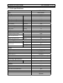
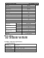
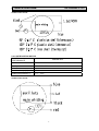
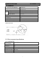
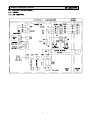
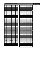
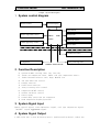
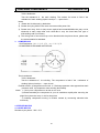
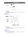
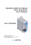
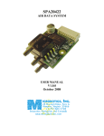
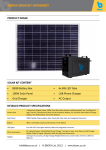
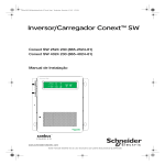
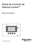
SPLIT
TYPE
AIR
CONDITIONER
AS-12HR4SVTVC
Type of contents
1. OPERATION RANGE
1
2. SPECIFICATION
2
3. INSTALLATION
7
4. ELECTRICAL DATA
8
5. CONTROL MODE
11
6. TROUBLE SHOOTING
22
7. CHECKING COMPONENTS
24
8. PANEL INSTRUCTIONS
28
9. PART LIST AND EXPLODE VIEW
30
NOTE: The figure,size and parameter of the product may not be identical with the
service manual, please take the actual product as the standard.
AS-12HR4SVTVC
1. OPERATING RANGE
COOLING
HEATING
Temperature
Indoor Air Intake Temp.
Outdoor Air Intake Temp
Maximum
32℃ D.B./23℃ W.B.
43 ℃ D.B./26℃ W.B.
Minimum
21℃ D.B./15℃ W.B.
21 ℃ D.B./15℃ W.B.
Maximum
27℃ D.B./18℃ W.B.
24℃ D.B./18℃ W.B.
Minimum
20℃ D.B/≤15℃ W.B
-7℃ D.B./-8℃ W.B.
1
2. SPECIFICATIONS
AS-12HR4SVTVC
2-1. Unit specifications
Model No.
Type
Ratings
AS-12HR4SVTVC
H/P,ON/OFF
Cooling Capacity
Btu/h
Heating Capacity
Btu/h
Rated Input-Cooling
W
Rated Input-Heating
W
Moisture Removal
L/H.r
Air Circulation
m3/h Max
EER for Cooling
Btu/h.W, W/W
COP for Heating
W/W
Energy Class
Cooling
Energy Class
12200
13600
1115
1104
1.5
550
10.94, 3.21
3.61
A
A
R410a
1080
37
32
54
Heatling
Refrigerant
Refrigerant charge volume
Indoor Unit Noise Level
Outdoor Unit Noise Level
g
High(dB (A))
Low(dB (A))
dB (A)
Power Supply
Voltage, Frequency, Phase
Rated Current
LRA
220-240V~,50Hz,1P
5.3
5.1
28
V
Cooling (A)
Heating (A)
A
System
Rotary
PA145X2C-4FT
TOSHIBA
Capillary
Copper tube and Aluminum Fin
Copper tube and Aluminum Fin
Compressor type
Compressor Model No.
Compressor MFG
Expansion Device
Evaporator
Condenser
Connecting Pipe Diameter
Liquid Pipe
inch
Gas Pipe
inch
1/4
1/2
Features
LED
Yes
Yes
Yes
Optional
Optional
Display on Front Panel
LCD Wireless Remote Controller
Removable and washable Panel
Washable PP Filter
Active Charcoal Filter
Electrostatic Filter
2
2. SPECIFICATIONS
AS-12HR4SVTVC
Optional
Optional
Optional
Optional
Optional
Optional
Yes
Yes
Yes
Yes
Yes
Yes
Yes
Yes
Yes
HEPA Filter
LTC Filter
Catechin filter
Negative ion filter
Photic Catalyst filter
Vitamin-C filter
24 Hours Timer
3 Speed and Auto Indoor Fan Control
Vertical Auto Swing Louver
Manual Adjustable Horizontal Swing Louver
Sleep Operation
Smart Function
Super Function
Compressor Indicator
Auto Restart
Other
Net Dimensions
Indoor Unit
WxHxD (mm)
Outdoor Unit
818x270x192
715x482x240
10
32
910X380X285
844x531x366
12
35
106/230/255
CE, WEEE,RoHS
Indoor Unit
Net Weight (Kg)
Outdoor Unit
Packing Dimensions WxHxD
Indoor Unit
(mm)
Outdoor Unit
Indoor Unit
Gross Weight (Kg)
Outdoor Unit
Loading Capacity (20'/40'/40'HC )
Approvals
NOTE :Test conditions:
Cooling : Indoor: DB27℃/ WB19℃
Heating: Indoor: DB20℃/ WB15℃
Outdoor: DB35℃/ WB24℃
Outdoor: DB7℃/ WB 6℃
2-2. Major component specifications
2-2-1.INDOOR FAN MOTOR
ELECTRIC
PERFORMANCE
PARAMETER
Rated power source
DG13G1-05
208V~240V; 50Hz~60Hz
Poles
4
Rated load output(W)
12W
Ambient temperature(℃)
-5℃~+43℃.
Motor model
3
2. SPECIFICATIONS
AS-12HR4SVTVC
WIRING DIAGRAM
2-2-2 OUTDOOR FAN MOTOR
ELECTRIC
PERFORMANCE
PARAMETER
Motor model
+DG13Z1-10
Rated power source
208~240V
Poles
----
Rated load output(W)
25W
Ambient temperature(℃)
-5℃~+43℃.
50Hz
WIRING DIAGRAM
4
2. SPECIFICATIONS
AS-12HR4SVTVC
2-2-3. COMPRESSOR
ELECTRIC PERFORMANCE
PARAMETER
Compressor model
PA145X2C-4FT
Compressor type
Rotary
Motor type.
PSC
Winding resistance(at 20℃)
Oil type
Main:2.31Ω±5%, aux:3.23Ω±5%
35uF/450V
1
RB68AF/T68/A68tf
Oil charge (cc)
480
Input power(W)
1195W/1235W (+5%)
Current (A)
5.52A/5.34A (+5%)
Ambient temperature(℃)
-5℃~+43℃.
Motor
Running capacitor
Number of cylinder
WIRING DIAGRAM
2-3. Other component specifications
2-3-1. LOUVER MOTOR
ELECTRIC
PERFORMANCE
PARAMETER
Stepper Motor model
DG13B1-09
Voltage(DC)
12V
Number of phase
4
Drive mode
1-2 phase excitation unipolar drive
Resistance per phase
200Ω±7%
Relative humidity(RH)
45%~85%
Temperature range(℃)
-10℃~+40℃.
5
2. SPECIFICATIONS
AS-12HR4SVTVC
WIRING DIAGRAM
M
5 ( red )
3 ( yellow ) 1 ( blue )
2-3-2. PANEL MOTOR
PARAMETER
ELECTRIC
PERFORMANCE
Stepper Motor model
DG13B3-02
Voltage(DC)
12V
Number of phase
4
Drive mode
1-2 phase excitation unipolar drive
Resistance per phase
90Ω±7%
Relative humidity(RH)
45%~85%
Temperature range(℃)
-10℃~+40℃.
WIRING DIAGRAM
6
3. INSTALLATION
AS-12HR4SVTVC
1、How to choose an air conditioner:
a. Choice for reference: 150-170W/㎡ for average rooms;
b. Choice for reference: 160-200W/㎡ for small size offices;
c. Choice for reference: 220-350W/㎡ for restaurants;
d. Choice for reference: 200-300W/㎡ for entertaining venues;
e. Choice for reference: 220-280W/㎡ for the top floor.
Note:1W = 3.412btu.
2. Indoor Unit:
For indoor unit installation, the distance between its top and the ceiling shall
not be less than 10 cm -20 cm, and the distance from the ground should be between
2m to 2.6m. Also the wallboard must be smooth and straight, with its supporting force
of not less than 60 kg.
The location for installing the indoor unit shall be far away from heat source,
the space between it and the door or window should exceed 0.6m
3. Outdoor Unit:
The air conditioner outdoor unit should not occupy public sidewalks, the
distance between the mounting bracket installed along the road (on condition that
the mounting bracket does not affect the public access, it can be installed
horizontally) and the ground must exceed 2.5m. Also we shall remember that: a. the
air flow must run freely. b. we should protect famous ancient buildings during
installation. c. the installation does not affect the traffic.
The distance between air outlet of outdoor unit and the opposite object should
be more than 1 meter, otherwise the machine would stop running because of overload
by heat yield failure.
If the outdoor unit was opposite the resident's door or window, you should
install the machine as far as possible away from the adjacent doors windows and plants,
and the distance shall not be less than the following values: for the rated cooling
capacity not more than 4.5KW, the distance should be 3m.; for the rated cooling
capacity more than 4.5KW, the distance should be 4m.
It should remember to avoid installing at places where the natural environment
is harsh, such as heavy fumes and wind, direct sunlight or high-temperature and heat,
together with the place where children easily reach.
4. The Unit:
When installing the air conditioner, the outdoor unit should be below the indoor
unit so as to facilitate circle of refrigerant and refrigeration oil .
The height difference between wall mounted indoor unit and the outdoor unit
is generally not more than 5 meters.
The connection pipe can't exceed 5 meters, and the longest is 10 meters. ⑵ when
the length exceeds 5 meters, 15g fluoride is required to be added for each exceeding
1m.
7
4. ELECTRICAL DATA
AS-12HR4SVTVC
4-1.Electrical wiring diagrams
4-1-1.INDOOR
4-1-1 AS-12HR4SVTVC
8
4. ELECTRICAL DATA
AS-12HR4SVTVC
4-1-2. OUTDOOR
4-1-2-1. AS-12HR4SVTVC
4-2-1.THE PARAMETER OF SENSOR:
1. THE PARAMETER OF THE COIL AND INDOOR AND OUTDOOR SENSOR:(R0=15K±2%)
T(℃)
R(KΩ)
V(v)
A/D
T(℃)
R(KΩ)
V(v)
A/D
-20
152.5
4.5522388
E8
30
11.99
2.221193
71
-19
143.9
4.528005
E7
31
11.47
2.1666037
6E
-18
135.8
4.5026525
E6
32
10.98
2.113164
6C
-17
128.3
4.4766225
E4
33
10.51
2.0599765
69
-16
121.1
4.4489346
E3
34
10.06
2.0071828
66
-15
114.5
4.4208494
E1
35
9.634
1.9554275
64
-14
108.2
4.3912338
E0
36
9.229
1.9045359
61
-13
102.3
4.3606138
DE
37
8.842
1.8542907
5F
-12
96.73
4.3287389
DD
38
8.474
1.8049757
5C
-11
91.51
4.2958408
DB
39
8.123
1.7564762
5A
-10
86
4.2574257
D9
40
7.789
1.7089385
57
-9
81.97
4.2265649
D8
41
7.47
1.6622163
55
-8
77.62
4.1902397
D6
42
7.165
1.6162869
52
-7
73.52
4.1527338
D4
43
6.875
1.5714286
50
-6
69.05
4.107674
D1
44
6.597
1.5272955
4E
9
4. ELECTRICAL DATA
AS-12HR4SVTVC
-5
66.01
4.0741884
D0
45
6.333
1.4843201
4C
-4
62.58
4.033256
CE
46
6.08
1.4421252
4A
-3
58.34
3.9773657
CB
47
5.838
1.4008062
47
-2
56.29
3.947959
C9
48
5.608
1.3606366
45
-1
53.41
3.9036691
C7
49
5.387
1.3211851
43
0
50.69
3.8582737
C5
50
5.177
1.2828964
41
1
48.12
3.8117871
C2
51
4.976
1.2454946
40
2
45.7
3.7644152
C0
52
4.783
1.2088662
3E
3
43.41
3.7159733
BE
53
4.599
1.1732741
3C
4
41.25
3.6666667
BB
54
4.423
1.1385986
3A
5
39.2
3.6162362
B8
55
4.255
1.1049078
38
6
37.27
3.5651425
B6
56
4.093
1.0718588
37
7
35.44
3.5130849
B3
57
3.939
1.0399176
35
8
33.71
3.4602751
B0
58
3.792
1.00894
33
9
32.08
3.4069669
AE
59
3.65
0.9785523
32
10
30.63
3.3563445
AB
60
3.515
0.9492304
30
11
29.06
3.2977758
A8
61
3.385
0.9205874
2F
12
27.68
3.2427366
A5
62
3.261
0.8928865
2E
13
26.36
3.1866538
A3
63
3.142
0.8659464
2C
14
25.12
3.1306082
A0
64
3.028
0.8398047
2B
15
23.84
3.069001
9D
65
2.918
0.814265
2A
16
22.82
3.0169223
9A
66
2.813
0.7895919
28
17
21.76
2.9597388
97
67
2.713
0.7658217
27
18
20.75
2.9020979
94
68
2.618
0.7429901
26
19
19.79
2.8442081
91
69
2.524
0.7201552
25
20
18.88
2.7863046
8E
70
2.436
0.6985547
24
21
18.03
2.729337
8B
71
2.36
0.6797235
23
22
17.21
2.6715306
88
72
2.268
0.656706
21
23
16.44
2.6145038
85
73
2.189
0.6367444
20
24
15.7
2.5570033
82
74
2.114
0.617623
1F
25
15
2.5
80
75
2.041
0.5988498
1F
26
14.33
2.4428912
7D
76
1.971
0.5806965
1E
27
13.7
2.3867596
7A
77
1.905
0.5634428
1D
28
13.1
2.3309609
77
78
1.84
0.5463183
1C
29
12.53
2.2756992
74
79
1.778
0.5298605
1B
80
1.719
0.5140858
1A
10
AS-12HR4SVTVC
5. CONTROL MODE
Chapter 1 System Description
1. System control diagram
Remote control
Remote Display
Jiggle Switch
Room temperature sensor
Indoor
circuit
PCB
Panel motor
Indoor fan motor
Indoor pipe temp. sensor
louver motor
Outdoor fan motor
4-way reversing valve
Compressor
Outdoor control circuit
2. Function Description
a)
b)
c)
d)
e)
f)
g)
h)
i)
j)
k)
l)
Operation Mode: Cooling, Heat, Dry, Fan only.
Intake air temperature sense, Indoor coil pipe temperature sensor .
Indoor Fan mode Selector: Auto, High, Medium, Low.
Air flow direction control
Display function
Panel switch function
4-way reversing valve control
Compressor ON/OFF control
Outdoor fan motor control
Error inquiry
Ceased delay protection for compressor
Room temperature display(optional)
3. System Signal Input
Remote control signal, room temperature signal, coil pipe temperature signal,
“ON/OFF” signal, Jiggle Switch signal.
4. System Signal Output
1.1 H/C split unit: louver motor(step motor), panel motor(step motor), indoor fan
11
AS-12HR4SVTVC
5. CONTROL MODE
motor(PG regulating motor or tapped regulating motor), 7-segment tube and LED
display, Buzzer, Outdoor fan motor, Coil of the 4-way reversing valve, Compressor( or
AC contactor).
1.2 Cooling only split unit: louver motor(step motor), panel motor(step motor),
indoor fan motor(PG regulating motor or tapped regulating motor),7-segment tube and
LED display, Buzzer, Outdoor fan motor, Compressor( or AC contactor).
5. Operation Mode
5.1 Operation mode
Cooling mode: Heat mode, Dry mode, Fan only mode.
5.2 Mode and function combination
These 4 modes contain the combination of the hereinbefore functions, and run these
operations control by remote control also.
5.3 Emergent start
If the appliance under the Stand-by state, all the Operation Mode, Air volume,
Temperature Setting , Delay time of Real Time Setting(High end) and Forced Cooling
function will be restored as the last time setting when you press on the “ON/OFF”
button, but lost the Air flow direction setting, Delay time of Non-real Time
Setting(Low end), and sleep function.
If the appliance was connected to the power at first time, it would operate
in smart mode, and set the mode, swing louver angle and the Air volume when you
press the “ON/OFF” button. It will keep in stand-by state if you press the
“ON/OFF” button during the normal operation.
5.4 Other control mode
(1) When the PCB circuit was connected to the power at first time, the buzzer
triggered and beep.
( 2 ) The compressor responded the variation of temperature after the
compressor operated in 3 min, and it will be ceased for 3 min then re-start.
When the operation mode changed or power off, the compressor turned off
immediately. For the other normal operation, the compressor has a 3 min delay
protection. If the compressor Power ON or OFF, the outdoor fan motor will be
ON or OFF correspondingly.
(3)The appliance is ceased for 3 min delay protection when the auto-restart
after blankout.
(4)The appliance is ceased for 5 sec delay protection to perform the other
operation after it receive the signal of specific operation, but no any delay
for the response.
(5)When the appliance power OFF, the indoor fan motor operated as below
condition:
a.Cooling and Dry mode: After the compressor power off, it will be operated in 30
sec under the presetting speed then turn off.
b.Fan only mode: it will be stopped immediately after the compressor power off.
c.Heating mode: After the compressor stopped, the indoor fan motor will stop if the
indoor coil pipe lower than 33℃, otherwise the indoor fan motor would operate on the
12
AS-12HR4SVTVC
5. CONTROL MODE
Low air speed setting to cool down the coil pipe, and it would stop for the max 30 sec.
(6)When the Heating mode set at first time or turn to the Heating mode from other mode,
the 4-way reversing valve will be triggered after the compressor power ON. If the
appliance turn off under the Heating mode, the 4-way reversing valve would be OFF after
3 min delay.
Chart 2 System Function Design
1. Function description
1.1 The appliance could be operate by Manual and Remote control, and the Remote
control could be set all the smart, Cooling, Dry, Heating and Fan only functions.
1.2 The temperature setting range from 18℃ to 32℃; and the indoor air temperature
sensor working range from 15℃ to 33℃.
1.3 Indoor air volume setting:
RPM
High
Medium
Low
Heat
Refer to the parameter list
Cooling
Refer to the parameter list
Dry
According to the Dry mode
Fan only
1.4 Indoor louver swing control
the RPM same as Heating mode
1.5 Overcooling protection control(only available for Cooling)
1.6 Anti-cold air system(only available for Heat Pump)
1.7 Auto-Defrost(only available for Heat Pump)
1.8 Overheating protection of heater exchange (only available for Heat Pump)
1.9 3 minutes delay protection for compressor
1.10 Timer operation
1.11 Self-diagnosis
1.12 Display function
1.13 Panel switch function
1.14 Auto-restart after blankout
1.15 Error inquiry
1.16 Super
1.17 Room temperature display(optional)
2. General protection system
General protection system means the appliance would be protected when overloading,
high temperature and high pressure occurs during the each operation mode(Cooling,
Heat, Dry and the smart mode). If the appliance works under some special mode, the
specific protection system would be triggered respectively.
2.1 Compressor delay protection
13
AS-12HR4SVTVC
5. CONTROL MODE
The compressor is ceased for 3 minutes to balance the pressure in the refrigeration
cycle in order to protect the compressor.(This protection include the Cooling or
the exchange Dry and Heat mode, but the unit has no this function after it restored.
If the unit restored and turn ON, then this protection would be functioned.)
2.2 Fan motor(PG motor) protection
When the Fan motor(PG motor) receive the signal, it will be stopped after it
detected the speed less than 200RPM.
3. Display function
Running status indication light and dual-bit digital tube should be lighted after
the opening of panel, Strip lights will turn bright and dark softly in a certain
frequency(concrete frequency will change freely according to the effect).
Compressor lights(blue, normal brightness): wlii be lighted when compressor is
running. Under special mode,they will follow the corresponding pattern rules.
Run light(blue, normal brightness): wlii be lighted when the machine is in the
running state . Under special mode,they will follow the corresponding pattern rules.
Timer light(blue, normal brightness): wlii be lighted when the machine is in the
timer state . Under special mode,they will follow the corresponding pattern rules.
Sleep light(blue, normal brightness): wlii be lighted when the machine is in the
sleep state .
Decorative strip lights (blue, high brightness): lighted when the machine is
open,and change from bright to dark,and then from dark to bright, repeatedly change
gradually.
Digital display (blue, normal brightness): LED tubes will shown set temperature when
running, and shown “- -” on dehumidification mode and air distribution mode . When
on timer mode, the LED tubes will show the set temperature for 10 seconds and then
show the time(without the real-time timier state).
4.Panel Switch Function
When air-conditioning is on power,the panel is reset through the feedback signal
of jiggle switch. If the signal sent by jiggle switch is disconnect signal,it means
the panel is open, then close the panel;If the signal is jiggle switch closed signal ,
the panel is closed , the panel does not move.
When the air-conditioning is open,step motor of panel will open from 0º to the
open-angle (VC is 80 º temporary, VC2 is 103 º temporary); When the air-conditioning
is closed,the panel will reset to the closed state according to the closed angle
(VC is 92 º temporary, VC2 is 76 º temporary),step motor of the panel stop immediately
when the controller reads the closed signal of panel switch.
If the jiggle switch state have not changed after the panel starts move for 20
seconds,then the micro-switch will be identified damage,then the panel actions
14
AS-12HR4SVTVC
5. CONTROL MODE
according to the following rules:
After on power, the panel will reset(means closed) according to the closed angle,in
open state the panel will open according to the open angle,closed state will
according to the closed angle,the base is the closed angle.When the operation
comeback valid after on power,the status of the panel keeps the same as the status
before power
5. Operation Mode
The appliance could be operated under Heat, Cooling, Dry and Fan Only mode, and
also the super, smart operation mode
5.1 Fan Only Mode Operation
During the appliance run in this mode, the compressor and outdoor fan stop, the
indoor fan operate under the pre-setting of air volume, and the louver swing, and
the indoor fan speed same as the Heating Mode.
5.2 Cooling Mode Operation
5.2.1 This mode could be selected by the remote control
5.2.2 The 4-way reversing valve will be stopped under this mode.
5.2.3 During this mode, the temperature setting, air volume and air flow
direction could be adjusted.
During the appliance run in normal condition, the compressor’s temperature
can only be adjusted by 1℃ up and down base on the setting temperature, the
compressor operation diagram is shown as following.
When the temperature dropped, the compressor will be power on.
The setting temp. plus 1℃
The setting temp. minus 1℃
Compressor power OFF
Temperature rise
Temperature fall
Compressor power ON
Compressor power ON
Compressor power OFF
5.2.4 Overcooling protection control
When the indoor coil pipe temperature is lower than 3℃ and higher than -7
℃ during Cooling or Dry operation for 3 min, indoor fan speed turns to high
and outdoor fan turn off. After the temperature recovers to 7℃, the air
conditioner turn to run in normal condition. When the indoor coil pipe
temperature falls below –7℃ during COOLING or DRY operation for 3 minutes,
15
AS-12HR4SVTVC
5. CONTROL MODE
the compressor and outdoor fan motor turn OFF. When the indoor pipe
temperature recovers to 5℃ and the compressor has been stopped for 3 minutes,
the compressor and outdoor fan motor will be turned ON.
5.2.5 Indoor fan operation
(1) When room temperature is higher than 35℃, the compressor is ceased
for 1 min then turn on, (when the compressor ceased for 3 min protection,
the indoor fan should be turn on immediately
(2)When the indoor fan keep in running condition, this operation state could
be controlled by the remote control with High, Median, Low and Automatic
setting.
(3)When the appliance is set Automatic condition in the Cool mode for the first time,
the fan speed will run at Low setting. After that, temperature and fan speed is shown as
following.
The setting temp. plus 3℃
High
Temperature fall
The setting temp. plus 2℃
Median
Median
The setting temp. plus 1℃
low
The setting temp.
Low
5.2.6 Air flow direction control
The louver is derived by a step motor, and it swings the horizontal louver automatically.
Press the SWING button to swing or stop the louver.
During the louver swing in normal operation, the current position will be stored. When
the appliance turn off and louver swing automatically to the default position, it will
position at the stored position plus 5º.
5.3 Dry mode operation
When the appliance run into the Dry mode, it starts as Cooling mode operation. If 3 minutes
elapses after starting, the appliance will sense the intake air temperature and minus 2℃ as the
setting temperature and operate in Cooling mode, and the indoor motor speed is low. During this
operation, the air flow direction could be set but the air volume is unavailable, and the setting
temperature can only be adjusted by 2℃ up and down(the minimum accuracy is
1℃).
When the appliance run in this mode, it will not influenced by under the 18℃ limit.
5.4 Heating mode operation
5.4.1 The 4-way reversing valve is turn ON under the Heating mode.
5.4.2 During this mode operation, the setting temperature and air volume
16
AS-12HR4SVTVC
5. CONTROL MODE
can be adjusted, and the air flow direction could be swang.
When the appliance run in normal condition, the compressor’s temperature
can only be adjusted by 1℃ up and down base on the setting temperature,
the compressor operation diagram is shown as following.
When the temperature rose, the compressor will be power ON.
Compressor power OFF
The setting temp. plus 1℃
The setting temp. minus 1℃
Compressor power ON
Temperature rise
Temperature fall
Compressor power OFF
Compressor power ON
5.4.3 Indoor fan motor operation
Anti-cold air system
When the appliance run in Heat mode condition, the indoor fan motor operation
is shown as following to prevent the cooling air come out during the appliance
operation.
The setting air flow
30℃(#27)
Extra-low
25℃(#28)
Stop
Low
Temperature rise
Temperature fall
35℃(#26) The setting air flow
Stop
When the appliance turn in the anti-cold air system in the Extra-LOW (Tapped
motor set in LOW, sic passim) during the compressor operation, the louver swang to the
Cool air protection position, the louver recovers to the original position after the air
volume change to LOW. When the room temperature reach to the setting temperature,
the compressor will be turn off, and the air flow change to LOW, the louver swang to
the Cool air protective position to prevent the air drop into human body directly; when
the indoor pipe coil temperature drop continuously, it will turn in the Cooling air
5.4.4 The indoor fan motor will operate according to the different
setting(High, Median, Low and Automatic) by the remote control, but the
anti-cold air system is prior.
When the appliance run in the Heat mode with the Automatic setting at first time, the
fan speed will be in the LOW setting, and the operation diagram is shown as following
17
AS-12HR4SVTVC
5. CONTROL MODE
The setting temp.
Temperature fall
The setting temp. minus 1℃
Median
The setting temp minus 2℃
Median
Temperature rise
low
low
high
The setting temp minus 3℃
high
5.4.5 Overheating protection control
When overloading occurs during the heating operation, this system controls
the outdoor fan motor and compressor according to the indoor coil pipe
temperature to prevent the overloading of the compressor and restrict the
pipe pressure to rise up. When the indoor pipe temperature exceeds 53℃, the
outdoor fan motor will be turned OFF, and when the indoor pipe temperature
falls below 49℃, the outdoor fan motor recovers to ON; When the indoor pipe
temperature exceeds 63℃, the appliance will be turned OFF .
4.4.6 Air flow direction control
The horizontal louver is controlled by a step motor, press the SWING button to swing or
stop the louver.
During the louver run in normal operation, the current position will be stored. When the
appliance turn off and louver swing automatically to the default position, it will position
at the stored position plus 5º.
5.5 Smart control
When the appliance operates at smart, the air flow direction can be adjusted.
(1) H/C appliance
a. When the setting temperature is 26℃, the appliance will be ran in the
Cool if the room temperature exceeds 26℃.
b. When the room temperature exceeds 23℃, but below 26℃, it will be ran
in the Dry mode(It will turn in Automatic setting After 3 min LOW air volume
running.).
c. When the room temperature exceeds 21℃, but below 23℃, it will be
operated in the Fan only, the air volume is set by LOW and the fan speed
can be adjusted
d. When the room temperature is not more than 21℃, it will be operated in
Heat mode, and the temperature is set to 22℃.
(2) Cool only appliance
a. When the room temperature exceeds 26℃, it will be ran in Cool mode, and
the temperature is set to 22℃.
b. When the room temperature exceeds 23℃, but not more than 26℃, it will
18
AS-12HR4SVTVC
5. CONTROL MODE
be operated in the Dry mode.
c. When the room temperature is not more than 23℃, it will be operated in
the Fan only, the air volume is set to LOW and the fan speed can be adjusted
After the appliance start the smart operation, the setting temperature can
be adjusted 2℃(the min accuracy is 1℃) up and down base on the automatic
temperature setting, also the presetting temperature of PCB circuit.
In case of the specific operation selected, it could be re-select the other
modes after the compressor ceased for 5 min or the setting temperature
changed.
5.6 Super
Whether the appliance is in operation or stand-by, when the “Super”signal
is received from the remote control, it will operated at the Cool mode and
set the temperature at 18℃ and fan speed setting is High.
6.
Supplementary
6.1 Time mode operation
Real time of Timer with remote controls can be suit for the appliance.
5.1.1 Real time of Timer setting
(1) The max Timer ranges is 24 hours.
(2) Timer ON/OFF
(3) Timer ON/OFF can be set available in turn.
(4) The Timer accurate more than 97%
(5) The Timer can be adjusted by 1 min increase.
(6) The appliance can be set the ON-Timer and OFF-Timer in the same time,
but no any timer setting indicated.
6.2 Sleep mode operation
(1) The Sleep mode can only be set during Cool, Heat and Dry mode.
(2) When the appliance run in the Sleep mode, it will stop after 8 hours
operation, then it will cancel the Sleep setting. When the appliance operate
under the OFF-Timer setting condition, if the OFF-Timer setting less than 8 hours,
it will keep the Sleep mode till the OFF-Timer setting; if the OFF-Timer setting
more than 8 hours, it will cancel the OFF-Timer setting after the Sleep mode
OFF.
(3) When the Sleep mode is select with Cooling mode, if the room temperature
not less than 26℃, the setting temperature will not be adjusted, otherwise,
the setting temperature will be raised by 1℃ per hour, but the max setting
temperature raise is 1℃.
(4) When the Sleep mode is select with Heat mode, the setting temperature will
be decreased by 1℃ per hour during the successive 3 hour, but the max setting
temperature decrease is 3℃.
(5) When the appliance operate with Sleep mode, the indoor fan run in the LOW
19
AS-12HR4SVTVC
5. CONTROL MODE
setting, and the air flow direction same as the last setting and the temperature
and air flow direction can be adjusted by user. The Running indicator will be
flashed 10 times per 1 Hz frequency, then all the indicators turn OFF except
the Sleep light after 5 min elapse. Those indicators will be recovery when the
temperature or Time setting is adjusted, after the setting, the indicators will
be lit in 10 sec, then turn OFF except the Sleep light.
6.3 Self-diagnosis
6.4
The room temperature and indoor pipe temperature are the important factor
for the appliance operation, when the room temperature sensor broken or
shorted is detected, it will set the room temperature at 23℃, and the
compressor will be cycled with power ON in 20 min and OFF in 3 min.
When the temperature sensor of the indoor pipe coil temperature broken or
shorted is detected, it will set the indoor pipe temperature at 35℃, and
the compressor will be cycled power ON in 20 min and OFF in 3 min. if the
appliance run in Heat mode, it will be cycled Defrost in 8 min when the total
run time of compressor exceed 50 min.
When the failure of the room temperature and indoor pipe temperature sensor
occurs, the compressor will be cycled with Power ON 20 min successively and
OFF 3 min. When the indoor pipe failure occurs, the protection will be
cancelled and the Defrost will be operate as aforesaid.
Error inquiry
The Error inquiry should be operate in the stand-by state, keep 5 sec press and hold on
the Emergency button, the error code will be displayed in 10 sec, then the control panel
display will recovery to the original. If two or more malfunction happened, each error
code will be displayed alternatively. If the appliance could save information under no
power condition, then the error code can be inquired as aforesaid with stand-by state
after power resume.
Error code: If the troubleshooting inquiry display by 7-segment tube, then the
error code will be displayed, otherwise only the running light ON.
Error
code
1
Ο:Flash
×:OFF
Power
Timer
Running
Sleep
Remark: ★:Light
1
2
3
4
Content
Remark
×
Ο
×
×
The failure for temperature sensor of
h/c
outdoor heater exchange
33
Ο
×
×
★
The failure for temperature sensor of
indoor pipe coil
34
Ο
×
★
×
The failure for temperature sensor of
indoor heater exchange
38
Ο
★
★
★
Indoor EEPROM failure
39
×
★
★
★
Indoor fan motor failure
41
Ο
★
×
★
The failure for Indoor
grounding protective
42
Ο
Ο
×
★
Overcooling protection
20
7,9,12,18K
7,9=-1 12=-7
AS-12HR4SVTVC
5. CONTROL MODE
43
Ο
Ο
★
×
Overheating protection
The failure is detected when the room temperature sensor broken or shorted over 5 sec.
The failure is detected when the temperature sensor of heater exchange broken or
shorted over 5 sec.
The failure is detected when each setting data is not match after the EEPPOM
self-check two times.
The failure is occur when the grounding signal is not detected with two
seconds after the appliance power ON.
6.5 Room temperature display (optional)
When the appliance operates with the Room Temperature Display, the room
temperature can be displayed in any mode except Sleep mode. It will display
the setting temperature in 10 sec after receive any signal from remote
control, then display
the room temperature. (Only is the Delay
time(Setting Timer) display with the Non-real time condition, include the
stand-by state)
Remark: The Room Temperature Display can be available after the EEPROM
parameter selection.
6.6 Auto-restart after blankout
When the appliance loses power during the normal operation, it will recover
with the last setting such as operation mode and temperature setting, except
the air flow direction after power ON.
When the appliance run in normal operation, the Emergent button is press
and hold for over 1.5 sec, and the buzzer beep 2 times, the Auto-restart
after blankout is available.
When the appliance run in normal operation, the Emergent button is press
and hold for over 1.5 sec, and the buzzer beep 1 times, the Auto-restart
after blankout is cancel.
21
6. TROUBLE SHOOTING
AS-12HR4SVTVC
6-1. Error codes
6-1-1.operating and display
6-1-2.Error codes:
The Error inquiry should be operate in the stand-by state, keep 5 sec press and hold on the Emergency button,
the error code will be displayed in 10 sec, then the control panel display will recovery to the original. If two or
more malfunction happened, each error code will be displayed alternatively. If the appliance could save
information under no power condition, then the error code can be inquired as aforesaid with stand-by state after
power resume.
Error code: If the troubleshooting inquiry display by 7-segment tube, then the error code will be
displayed, otherwise only the running light ON.
Error
code
Ο:Flash
×:OFF
Power
Timer
Running
Sleep
Remark: ★:Light
1
2
3
4
Content
Remark
h/c
1
×
Ο
×
×
The failure for temperature
sensor of outdoor heater
exchange
33
Ο
×
×
★
The failure for temperature
sensor of indoor pipe coil
34
Ο
×
★
×
The failure for temperature
sensor of indoor
heater
exchange
38
Ο
★
★
★
Indoor EEPROM failure
39
Ο
×
★
★
Indoor fan motor failure
41
★
★
×
★
The failure for Indoor
grounding protective
42
Ο
Ο
×
★
★
Overcooling protection
7,9,12,18K
7,9=-1 12=-7
Overheating protection
Ο
Ο
×
The failure is detected when the room temperature sensor broken or shorted over 5 sec.
The failure is detected when the temperature sensor of heater exchange broken or shorted over 5 sec.
The failure is detected when each setting data is not match after the EEPPOM self-check two
times.
The failure is occur when the grounding signal is not detected after the appliance power
ON.
43
22
6. TROUBLE SHOOTING
AS-12HR4SVTVC
6-2. TROUBLE SUSPENSION TABLE
SYMPTON
PROBABLE CAUSE
CORRECTIVE ACTION
The power source voltage
Repair the power supply
is lower than 198V
No voltage
The
RUN
indicator
(green)does not light up
Correct voltage
Repair general wiring
Replace control P.C.B or
display P.C.B
The
remote
controller
Reload new batteries
batteries are used up
No voltage between indoor
Replace the control P.C.B
The indoor fan does not fan motor terminals
function correctly
Indoor fan motor is broken
Replace indoor fan motor
No
voltage
between
outdoor fan motor terminals Replace the control P.C.B
on the indoor power P.C.B
No
voltage
between Check and repair electrical
outdoor fan motor terminals wiring between indoor and
The outdoor fan does not on the outdoor unit
outdoor units
function correctly
Outdoor fan is blocked
Remove obstructions
Outdoor
broken
fan
motor
Outdoor
fan
capacitor is broken
is
motor
Replace outdoor fan motor
Replace capacitor
No
voltage
between
compressor terminals on Repair control P.C.B
the indoor unit
Low
voltage
between
compressor terminals on Repair control P.C.B
the indoor unit
voltage
between Repair electrical
The compressor does not No
compressor
terminals
on between
indoor
start up
the outdoor unit
outdoor units
wiring
and
The running capacitor is
Replace running capacitor
broken
OLP of compressor trips
Wait for one hour or so
Compressor
shorted or broken
Replace compressor
23
winding
AS-12HR4SVTVC
7. CHECKING COMPONENTS
7-1.Check parts unit
1. INDOOR FAN MOTOR
.MOTOR EXAMINE AND REPAIR
Circuit diagram
Test in resistance.
TOOL: Multimeter.
Test the resistance of the main winding. The indoor fan motor is fault if the
resistance of main winding 0(short circuit)or∞(open circuit).
Notes:
1) Please don’t hold motor by lead wires.
2) Please don’t plug IN/OUT the motor connector while power ON.
3) Please don’t drop .Hurl or dump motor against hard material.Malfunction may not be
observed at early stage after such shock.But it may be found later,This type of
mishandling void our warranty.
Note:The wiring color for the motor may not be identical with the picture
shows, pls take the actual material as the standard
2. OUTDOOR FAN MOTOR
MOTOR EXAMINE AND REPAIR
24
AS-12HR4SVTVC
7. CHECKING COMPONENTS
Test in resistance.
TOOL: Multimeter.
Test the resistance of the main winding. The outdoor fan motor is fault if the
resistance of main winding 0(short circuit)or∞(open circuit).
Notes:
1) Please don’t hold motor by lead wires.
2) Please don’t plug IN/OUT the motor connector while power ON.
3) Please don’t drop .Hurl or dump motor against hard material.Malfunction may not be
observed at early stage after such shock.But it may be found later,This type of
mishandling void our warranty.
4) The wiring color of the motor may not be identical with the picture shows, please take
the actual material as standard.
3.
COMPRESSOR
1.Coil Resistance: Main:2.31Ω±5%, aux:3.23Ω±5%
2.COMPRESSOR EXAMINE AND REPAIR.
Test in resistance.
TOOL: Multimeter.
Test the resistance of the winding. The compressor is fault if the resistance of
winding 0(short circuit)or∞(open circuit)
Familiar trouble: 1)Compressor motor lock. 2)Discharge pressure value approaches static
pressure value .3)Compressor motor winding abnormality.
Notes:1)Don’t put a compressor on its side or turn over.
2) Please assembly the compressor in your air conditioner rapidly after removing the
plugs.Don’t place the comp. In air for along time.
3) Avoiding compressor running in reverse caused by connecting electrical wire
incorrectly.
4. STEPPER MOTOR
4.1 LUVER MOTOR
Resistance per phase:200Ω±7%
25
AS-12HR4SVTVC
7. CHECKING COMPONENTS
M
5 ( red )
3 ( yellow ) 1 ( blue )
Test in resistance.
TOOL: Multimeter.
Test the resistance of winding. The stepper motor is fault if the resistance of winding
0(short circuit)or∞(open circuit).
4.2 PANEL MOTOR
Resistance per phase:90Ω±7%
Test in resistance.
TOOL: Multimeter.
Test the resistance of winding. The stepper motor is fault if the resistance of winding
0(short circuit)or∞(open circuit).
7-2. Check others
1. FUSE
Checking continuity of fuse on PCB ASS’Y.
1) Remove the PCB ASS’Y from the electrical component box..Then pull out the fuse
from the PCB ASS’Y (Fig.1)
26
AS-12HR4SVTVC
7. CHECKING COMPONENTS
Fuse
PCB Ass抷
Fig.1
2) Check for continuity using a multimeter as shown in Fig.2.
Fuse
Fig.2
2.CAPACITOR
Remove the lead wires from the capacitor terminals, and then place a probe on the
capacitor terminals as shown in Fig.3.Observe the deflection of the pointer, setting the
resistance measuring range of the multimeter to the maximum value.
The capacitor is “good” if the pointer bounces to a great extent and then gradually returns to
its original position.
The range of deflection and deflection time differ according to the capacity of the
capacitor.
Multimeter
Compressor motor
capacitor
Fan motor
capacitor
Fig.3
27
8. Panel instruction
AS-12HR4SVTVC
8-1. Panel instruction
PANEL INSTRUCTIONS
1. Remove the three sliders to the right side, then
open the front panel.
2.Remove the screw, then open the safe cover.
3.Loose the plug connections of the panel motor
and the jiggle switch.
4.Remove the panel buckle with the tool. then
take out the front panel components.
5.a.Remove the screw of the motor cover, then
take out the motor cover.
b.Remove the two mounting screws, then can
change the panel motor.
28
8. Panel instruction
AS-12HR4SVTVC
6. a. Remove the two mounting screws, then take
out the jiggle switch cover.
b. Remove the mounting screw, then can
change the jiggle switch.
7. Remove the panel buckle with the tool. then
take out the front panel from the front panel seat.
8.Remove the parts step by step. then can
remove the transmission shaft.
29
9. PART LIST
AS-12HR4SVTVC
9-1. Indoor unit
9-1-1. Exploded View
9-1-2. Part list
Part List of Indoor Unit for AS-12HR4SVTVC
No.
DESCRIPTION
New Part No.
Q’ty
UNIT PRICE
$2.23
$13.98
$12.79
$4.26
$0.44
$33.87
$9.05
$0.34
$3.29
$1.75
$1.75
$2.79
$0.05
$0.07
$2.62
$10.69
$3.74
1
Installation Plate
1248031
1
2
Chassis
1246083
1
3
Indoor Fan Motor
1260336
1
4
Indoor Fan
1247636
1
5
Bearing
1223739
1
6
Evaporator Assembly
1249363
1
7
Cabinet
1246705
1
8
Glide hook
1248921
3
9
Decorative Board
1263779
1
10
Air Filter(Right)
1248250
1
11
Air Filter(Left)
1248282
1
12
Transmission Shaft
1248904
1
13
Axle Sleeve
1248736
2
14
Connecting Rod B
1248907
1
15
Front Panel Seat
1247162
1
16
Removable front panel
1247161
1
17
Remote Controller
1222186
1
30
KT13G0-13
G1J00/R00.01.01-00
DG13G1-05
DG22G1-13
KT33F0-04
G1J00/R01.04.01-00
G1J00/R00.02-01
G1J00/R00.02-07
G1J00/R00.02-03
KT31F30-08
G1J00/R00.02-05
G1J00/R00.02.01-03
G1C40/00.02-08
G1C40/00.02-09
G1J00/R00.02.01-02
G1J00/R00.02.01-01
+DG11E4-01(E)
9. PART LIST
AS-12HR4SVTVC
18
Jiggle Switch
1327018
1
19
Decorative Part
1263778
1
20
Connecting Rod A
1248905
1
21
Coupler
1258230
1
22
Panel Louver Motor
1260241
1
23
Display PCB Box
1276739
1
24A
Display PCB A
1361811
1
24B
Display PCB B
1361811
25
Displey Film
1276857
1
26
Display PCB Cover
1330809
1
27
Safety Cover
1276738
1
28
Right Decorative Board
1263780
1
29
Electric Box
1276599
1
30
Control PCB
1361710
1
31
Transformer
1222247
1
32
Thermistor
1222260
33
Pipe Assembly
1221862
1
34
Horizontal Louver
1248629
1
35
Clasp
1223749
1
36
Draining Pan
1248432
1
37
Louver Bearing
1222824
3
38
Drain Hose
1276892
1
39
Vertical Deflector
1248630
12
40
Right Gear pole
1248902
1
41
Left Gear pole
1248901
1
42
Louver Motor
1260312
1
43
Baffle
1248993
1
31
$0.89
$4.00
$0.06
$0.07
$5.41
$0.95
$6.90
$6.90
$0.81
$0.20
$0.69
$1.71
$2.87
$14.20
$3.76
$1.33
$5.32
$3.00
$0.08
$3.29
$0.12
$0.88
$0.10
$0.30
$0.30
$2.44
$1.48
+G1C40/00.05.02-00
G1J00/R00.02-02
G1C40/00.02-05
G1C40/00.02-10
DG13B3-02
G1J00/R00.05.01-01
K36430226
K36430226
G1J00/R00.05.01-04
G1J00/R00.05.01-05
G1J00/R00.02-06
G1J00/R00.02-04
G1G00/R00.05-01
K36412031
+DG20B0-07
+DG19R2-05
+G1G10/R03.04.02-00
G1J00/R00.01.02-02
G1A00/R00.00-02
G1J00/R00.01.02-01
KT25F0-05
KT20P0-10
G1J00/R00.01.02-03
G1J00/R00.01.02-05
G1J00/R00.01.02-04
DG13B1-09
G1J00/R00.00-01
9. PART LIST
AS-12HR4SVTVC
9-2.Outdoor unit
9-2-1. Exploded View
10
9
11
12
8
3
2
1
13
14
15
16
17
18
7
6
5
21
22
4
20
19
23
24
25
26
28
27
9-2-2. PARTLIST
Part List of Outdoor Unit for AS-12HR4SVTVC
No.
DESCRIPTION
New Part No.
Q’ty
UNIT PRICE
1
Outdoor Fan
1313821
1
$4.00
DG22Z1-20
2
Outdoor Fan Motor
1222216
1
$20.00
+DG13Z1-10
3
Motor Stay Bracket
1308210
1
$3.43
W1E0L/R00.02-05
4
Fan Guard
1276845
1
$3.50
W1E0D/R00.02.01-02
5
Cabinet
1247914
1
$7.33
W1E0D/R00.02.01-01
6
Top Cover
1247912
1
$5.60
W1E0L/R00.02.02-01
7
Chassis
1221623
1
$8.90
+W1E0D/R01.01.01-00
8
Side Support
1248091
1
$1.61
W1E0L/R00.02-03
9
Condenser
1249852
1
$45.00
W1E0S/R01.04.01-00
10
Back Lattice Plate
1247481
1
$1.32
W1E0D/R00.04-06
11
Thermistor
#N/A
#N/A
#N/A
#N/A
12
Capillary Tube Assembly
1255497
1
$6.00
W1E0D/R10.01.02-00
13
Bulkhead
1248504
1
$3.30
W1E0L/R00.04-03
14
4 Way Valve Coil
1222020
1
$3.00
+DG20S0-03(A)
15
4 Way Valve
1258657
1
$9.34
DG26D2-01(A)
16
Right Side Plate
1246331
1
$5.16
W1E0L/R00.04-02
32
9. PART LIST
AS-12HR4SVTVC
17
Terminal Cover
1276574
1
$0.67
W1A1L/00.02-01
18
3 Way Valve Assembly
1258658
1
$4.60
DG26C2-04(A)
19
2 Way Valve Assembly
1258653
1
$4.64
DG26B1-06(A)
20
Valve Fixing Plate
1248461
1
$1.67
W1A1L/00.01.01-03
21
Compressor
1224702
1
$114.00
PA145X2C-4FT
22
Fan motor Capacitor
1225552
1
$0.61
+CBB61-1.5μ/450-1
23
Capacitor Fixing Ring
1248747
1
$0.16
W1A1L/00.05-02
24
Compressor Capacitor
1225652
1
$3.36
+CBB65-35μ/450-1
25
Terminal Board 5PU
1221319
1
$1.00
+DG17D5-01
26
Electrical Assembly Plate
1276683
1
$1.29
W1E0L/R00.05-01
27
Power Supply Cord Clamp 1
1221112
1
$0.15
+KT14X0-10
28
Power Supply Cord Clamp 2
1221119
1
$0.15
+KT14X0-05
33