1
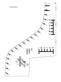
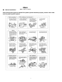
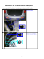
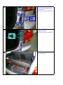
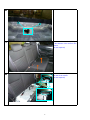
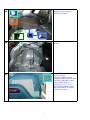
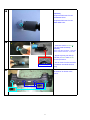
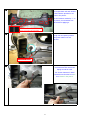
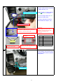
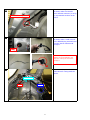
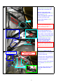
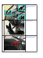
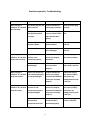
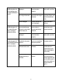
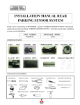
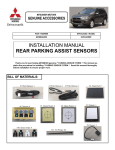
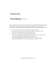
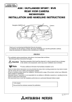
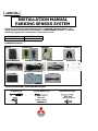
INSTALLATION MANUAL
PARKING SENSOR SYSTEM
Thank you for purchasing MITSUBISHI genuine * PARKING SENSOR SYSTEM *. This
manual explains the procedure for installing * PARKING SENSOR SYSTEM *. Read this
manual thoroughly before installation to ensure proper work.
PART NUMBER
MZ380466EX
APPLICABLE MODEL
Outlander Sport
COMPONENT PARTS
1.ECU
2.SENSOR (4)
5.MAIN HARNESS
4.SENSOR CLIP (4)
3.BUZZER
6.SENSOR HARNESS
A
7.SENSOR HARNESS
B
8.TEMPLATE A,B
B
9.STICKERS
10.SENSOR LOCATION
STICKER
φ24 (2)
11.CABLE TIE
φ26 (2)
TOOLS NECESSARY FOR INSTALLATION
SCREWDRIVER
DRILL
SOCKET WRENCH (10)
ORNAMENT REMOVER
HOLE SAW
(24mm) (26mm)
DRILL BIT
(3mm) (15mm)
1
A
Template B
2
Template A
3
PRECAUTIONS
Disconnect the negative pole cable from the battery before installation in order to avoid
possible electric shock or bodily injury
1. The parking sensor system detects the distance between a vehicle and obstacles nearby
when the vehicle moves backward and warns the driver of the distance with buzzer sound.
It is designed as a tool to enhance a driver’s comfort, but is not intended to relieve the
driver’s safety responsibility. Please remember to take all usual care even when using
this system.
2. As there is time lag between detection and real warning, please park your car at the speed
of no more than 10 km/h.
3. You will hear beep sound when the vehicle starts to move backward.
Please put on the brake softly when the warning alert starts to beep continuously.
4. Please turn down the radio when using this system so that the warning alert can be heard well.
5. Please prevent the sensors from being knocked hard or washed by high-pressure spray
guns to avoid damage.
6. Snow, mud, water drops or other substances on the sensors are likely to cause malfunction
of the system. Please always keep the sensor surface clean.
7. Please note that there could be possible system failure under the following circumstances:
> when the shape of an object to detect is pyramidal or acute
> when the system tries to detect an object which can easily absorb microwave
(e.g. fabric, snow, etc)
8. Please note that there could be possible misdetection under the following circumstances:
> when the vehicle moves on rugged, gravel, uphill and/or bushed roads
> when the level of the back of the vehicle is lower due to overload
> when the system is in the environment of 40KHz-noise from metal or high-pressure
gas exhaust
> when other accessories are equipped inside the system’s detection field
9. This system is suitable only for DC 12V vehicles.
4
※
Before Installation:
Main
Checkpoints
Start and stop the engine to check if the power system functions properly, such as door locks
and the power ignition system.
5
Instructions for Car Parts Removal and System
* Necessary tools for installation: General purpose tools, power drills, stabber
1
1. Remove the rear bumper
fasteners (4 locations)
2
2. Remove fasteners (5 locations)
inside both of the rear fenders.
(The picture shows the right side.)
6
3
3. Remove the bolts fixing the rear
bumper and the tailgate stopper
from both sides.
(The picture shows the right side.)
4
4. Remove both of the rear
combination lamps.
(The picture shows the right side.)
5
5. Remove the luggage tray.
(No tool required)
①
③
②
③
7
6
6. Remove the rear trim.
7
7. Remove the rear seat by lifting it
in the direction of the arrows in the
picture.
(No tool required)
8
8. Remove the scuff plate on the
left side of the vehicle.
(No tool required)
8
9. Remove the screws and
fasteners from the locations
specified in the picture.
9
10
10. Remove the trim panel on the
left side.
11
11. Prepare Template A by cutting
along the bold line.
Place the template along the
bumper line, mark the center point
of the circle, and paste a sensor
location sticker(φ24) in the
direction shown in the picture.
(The procedure applies to both
sides of the vehicle. The picture
shows the right side.)
9
12
12. Place Template B along the
reflector, mark the center point of
the circle, and paste a sensor
location sticker(φ26) in the
direction shown in the picture.
(The procedure applies to both
sides of the vehicle. The picture
shows the right side.)
13
13. Use a φ3-drill bit to make a
center hole.
14
14. Use a φ3-drill bit to make a
locator hole.
10
15. Drill holes.
15
[Important]
Use φ24 drill hole saw for two
OUTER SIDE holes.
Use φ26 drill hole saw for two
INNER SIDE holes.
16
1
16. Installation of sensors.
2
1. Insert the sensor into the to
hole and locate tentatively.
[Important]
Sensors with yellow connector : Outer side
Sensors with blue connector : Inner side
2. Adjust set prong into the φ3
hole that you have made in the
previous procedure.
3
Set prong
3. Put the hook from the back side
of connector and check the firm
fixing.
17. Install the sensors and "sensor
harnesses A" as shown in the
picture.
17
11
18. Fix the "sensor harnesses A" to
the bumper back side with stickers
at the locations specified in red
boxes in the picture.
18
*
*
*
For the locations marked by "*" in
the picture, cut the sticker into
halves before applying it.
*
For the locations marked by "*" in the
picture, cut the sticker into halves before
19. Route "Sensor harness B"
trough rear end panel grommet
along with vehicle rear end
harness.
19
Rear End Harnesses
20. Remove the grommet for rear
end harnesses and remove the
taping around the neck.
20
Put "Sensor harness B" naked
terminals into the tube from the
ction shown in the picture.
12
21. Disconnect the vacant male
connector (6Pins) that is connected
on "Main harness" (*A)
21
Sensor Harness Fixation Point
*B
Insert terminals of "sensor harness
B" into to the 6-pin connector.
Check the wiring location by color
as shown in below chart.
Tie "sensor harness B" near the
rear end harness clamper. (*B)
Rear End Harness Clamper
Remove vacant connector *A that
connected on "Main Harness" and insert
terminals of "Sensor Harness B"
*A
①
Confirm the color
matching
⑥
Back view
Insert terminals according to
the right-hand chart.
Check the codes are positioned
properly by code color after the
connectors are jointed.
CAUTION:
Please make sure of the color
matching of wiring harness when
install the terminal to the
connector.
№
①
②
③
④
⑤
⑥
Line color
N.C
White/Black Line
Orange/Black Line
Blue/White Line
Red/White Line
Yellow/Green Line
22. Restore the rear end harnesses
and the taping, and tie the sensor
harnesses at the locations specified
in the picture.
22
Tie Locations
13
23. When restoring the rear end
harnesses, make sure that the
sensor harness connector (*A of fig
21) is positioned as shown in the
picture.
23
Sensor Harness Connector
24. For vehicles without rear end
harnesses, make a small cross slit
on the blindfold plug with knife and
route the "Sensor harnesses B"
through it.
24
Plug
*1: Water-proof treatment with
sealant has to be applied to the
plug after routing the harnesses
through it.
*1
25. Refer to the picture for the
"Main Harness" routing inside the
vehicle.
25
BACK LIGHT
GND
ECU
14
26. Install Buzzer and ECU in the
tion specified in the picture with
adhesive tape on the back side.
26
Clean the fixing surface with
alcohol or mild detergent and dry it
before fixing the unit.
Remove the application paper and
press the unit down firmly.
*2
Connect "Main harness" 24-pin
nector to ECU.
ECU
Make sure not to install the ECU
within the area marked by *2 in
order to prevent its interference
with the rear quarter trim.
27. Connect the harnesses for
back-up lamp and GND at the
locations specified in the picture.
27
Back-up lamp: Remove black tape
(reuse) of vehicle wiring harness at
the area specified in the picture,
and pick up white wire. Then
connect Back up signal splice
connector, wrap the splice
connector
with vinyl
tape and
NOTE:
NOTE Insufficient
installation
and
locking ofthe
splice
connector
cause
restore
vehicle
blackmay
tape.
GND
disconnection. confirm the wire location
when locking, and make sure to lock
firmly
Back-up lamp
28
Connect "Sensor harness
B" and "Main Harness"
Range of Excessive Harnesses
to be Put Together
GND: Fasten together with the
28. Connect 6-pin connector of the
"Main Harness" to 6-pin connector
of "Sensor Harness B.
Put excess of the "Main harnesses"
and "buzzer wire" together and tie
it to vehicle harnesses.
Make sure to tie the wiring harness
at the locations specified in the
picture.
*3
Tie Locations
15
*3: Fix the 2-pin connector of the
buzzer with a cable tie at this
location.
29
29. For vehicles without rear end
harnesses, tie the main harnesses
at the locations specified in the
picture.
30
30. Connect the sensor harnesses
and restore the bumper.
31. Make a ø15 hole at the location
specified in the picture on the rear
quarter panel on the left side.
35
φ15
60
16
32. Remove release paper from the
back of the buzzer, route the
buzzer cables through the ø15
hole, and attach the buzzer to the
trim.
32
Attach the buzzer in a
way that the switch faces
rearward.
33. Bind up 200mm of the buzzer
cables and fix them to the trim
with stickers as shown in the
picture.
33
200
For the locations marked by "*" in the
picture, cut the sticker into halves before
34. Connect the 2-pin connectors
of the buzzer and of the main
harnesses together and restore the
rear quarter trim.
34
Connect connectors.
17
Product specification
Items
Specification
Rated Voltage
DC 12.0V
Operation Temp
-20℃
℃~70℃
℃
Storage Temp
-30℃
℃~80℃
℃
Reminder:
After installing the sensor system, please confirm that the system
functions properly. Temporarily reconnect the negative (-) cable to
the battery to test. Please also confirm that the original electronic
devices work properly before re-assembling the removed parts.
Then:
Restore cargo side trim (LH), rear scuff plate (LH), rear seat
cushion, rear trim, luggage tray, rear combination lamps, and fasten
all bolts and fasteners of the rear bumper.
Reconnect the negative (-) cable to the battery.
18
Function inspection- Troubleshooting
Symptom
Possible Cause
Confirmation Method
When the gear is
shifted to “R”, the alert
does not beep.
The buzzer plug has not
been inserted.
Confirm whether the
buzzer plug is inserted.
Insert the buzzer plug
correctly.
Tail light power wire
has not been spliced
correctly.
Check if reverse lights
are on or that the thick
white wire has been
spliced.
Splice the thick white
wire.
The fuse to the ECU
may have blown.
Check whether the fuse
has been blown.
Replace the fuse with a
new one.
ECU is damaged.
Confirm whether the
ECU is damaged.
Replace ECU with a
new one.
One or more of the
sensors is not
connected properly.
Confirm whether the
sensors are properly
connected.
Connect the plug of
each sensor properly.
One of the sensors may
be damaged.
Confirm whether each
sensor functions
properly.
Replace any damaged
sensor with a new one.
When the gear is
shifted to “R”, the alert
beeps three times.
Two of the sensors are
not connected properly
or may be damaged.
Confirm whether the
sensors are properly
connected and whether
each sensor functions
properly.
Connect the plug of
each sensor properly
and replace any
damaged sensors with
a new one.
When the gear is
shifted to “R”, the alert
beeps four times.
Three or more of the
sensors are not
connected properly or
may be damaged.
Confirm whether the
sensors are properly
connected and whether
each sensor functions
properly.
Connect the plug of
each sensor properly
and replace any
damaged sensors with
a new one.
The sensor’s harness
has not been
connected to the ECU.
Confirm whether the
harness has been
connected properly.
Connect the plug of the
harness to the ECU.
When the gear is
shifted to “R”, the alert
beeps twice, not once.
19
Solution
The gear is in “R” but
the warning does not
go off although there
are objects behind the
vehicle.
One of the sensors is
damaged.
Confirm whether each
sensor functions
properly.
Replace any damaged
sensor with a new one.
The objects are outside
the range of detection.
Refer to the service
manual for the range of
detection.
(The warning does not
go off when objects are
outside the detection
area).
ECU is damaged.
Confirm whether the
ECU is damaged.
Replace ECU with a
new one.
The gear is in “R” and
the warning goes off
for a while although
there is no object
behind the vehicle.
The sensor surface is
covered with foreign
materials such as mud,
water drops, etc.
Confirm whether the
sensor surface is
covered with foreign
materials.
Clean up the sensor
surface and see if it
functions normally.
One of the sensors is
damaged.
Confirm whether each
sensor functions
properly.
Replace any damaged
sensor with a new one.
The gear is in “R”, and
the warning goes off
intermittently although
there is no object
behind the vehicle.
The sensors are not
installed in the proper
position.
Confirm whether the
sensors are installed in
the proper position.
Reinstall the sensors in
the proper position.
The sensors have
detected harsh roads.
Confirm the road
condition.
(Misdetection is
possible when the
system detects harsh
roads or small objects
on the road.)
The vehicles posture is
weighted heavily to
one side.
Confirm the vehicles
posture.
Misdetection may
occur if the vehicle is
heavily weighted in the
rear or at the cusp of a
steep incline. (Refer to
service manual for
figure.)
20