1
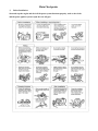
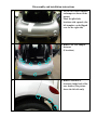
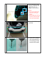
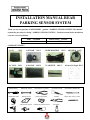
INSTALLATION MANUAL REAR
PARKING SENSOR SYSTEM
Thank you for your purchase of MITSUBISHI genuine * PARKING SENSOR SYSTEM * This manual
explains the procedure for fitting * PARKING SENSOR SYSTEM * . Read this manual before installation
to ensure correct installation .
PART
NUMBER
APPLICABLE
MZ380467EX
MODEL
i-MiEV
COMPONENT PARTS
1.ECU
1PCS
5.C-CLIP 2PCS
2.SENSOR
2PCS
6. SPONGE 10PCS
3.WIRE HARNESS
7.CABLE TIE
1PCS
10PCS
4.BUZZER 1PCS
8.Sensor Fix Paper 2PCS
Tools necessary for installation
SCREWDRIVE
MASKING TAPE
DRILL
WRENCH (10mm)
DIAGONAL CUTTERS
CENTER PUNCH
ORNAMENT REMOVER
DROP CLOTH
SAFETY GLASSES
PLIERS
DRILL BIT (3mm) (15mm)
HOLE SAW (26mm)
WATER PROOF SEALANT
ALCOHOL
Precautions
1. This system is designed to assist the driver with parking the vehicle. The system operates by detecting
ultrasonic waves that are reflected by obstacles behind the vehicle. This system is an aid for backing up
only and is not a substitute for your visual confirmation.
2. Due to the time requirement of the ultrasonic waves to be sent out and reflected while moving backwards,
please use speeds under 10km/h to move backward.
3. While using this system to move backward, please turn down the volume of the radio, so as not to drown
out the sound of the warning.
4. Prevent brute force or high-pressure washes from directly impacting the sensor. It is easy to damage the
sensor device.
5. Snow, mud, water droplets, foreign matter, etc. covering the sensor device may cause the device to falsely
detect. The device should be kept clean at all times.
6. The following obstacles are known to cause difficulty in detection, please note:
※Sharply angled barriers.
※Cotton, snow, etc are apt to absorb the object of the sound wave.
7. The following situations may lead to a false detection by the sensor, please note:
※While moving backward in a road full of bumps and holes. Reversing on a gravel road, grass road or
up a road with a slope.
※When the height of the automobile’s rear shortens because of a heavy load.
※When ultrasonic waves from another vehicle are present nearby.
※There is an environmental noise ( 40KHZ).
8. This system is only suitable for a vehicle using 12V.
9. The product is composed of two center back sensors. Please pay attention when reversing the car.
10. After installing, please hand over the manual to the customer.
Main Checkpoints
※
Before Installation:
Start and stop the engine and check if the power system functions properly, such as door locks
and the power ignition system. Open the rear tail-gate.
Disassembly and installation instructions
1
1. Put the left Sensor template
on bumper as shown in the
picture.
Mark the pilot-hole
locations with a punch. (the
left template can be flipped
over for the right side)
2
2. Remove the rear bumper
fasteners
(9 locations)
3
3. Remove fasteners (3
locations) inside both of the
rear fenders.(The picture
shows the left side only)
4
4. After removing the fender
fasteners on both the right
and left side, the rear
bumper can be removed.
CAUTION:
(1)Disconnect the light harness
before fully removing the
bumper.
(2)Add masking tape to the edge
of fender to protect the paint
when removing the bumper.
5
5. Remove the inside bumper
styrofoam.
6
6. On the removed bumper,
drill a 3mm pilot hole at
the locations previously
marked with the punch.
7
7 Use a 26mm hole-saw to
drill out the sensor locations
on the bumper. Take care to
center the hole saw to the pilot
hole closest towards the
bottom of the bumper.
Towards Bottom of Bumper
8
1
3
9
2
8-1. Position the sensor into
the hole.
8-2. Adjust the sensor so that
the notch on the sensor
alligns with the notch in
the drilled out hole.
8-3. Install the hook for the
back side of the sensor and
check for secure fitment
9. Remove the rear seat by
lifting it in the direction
of the arrows in the
picture.(No tool required)
10
10. Dismantle the left rear
Side scuff plate.
11
11. Remove the clips and
fasteners from the rear end
trim in the picture.
12
12. Dismantle the lower left
quarter trim panel.
CAUTION:
Use a drop cloth to cover the top
edge of the quarter trim panel
before removing.
13
13. Dismantle the upper left
quarter trim panel.
14
14. Route the harness as
shown below.(positions of
ECU, Buzzer, GND , Back
Light Splice)
ECU
Back
Light
To
Sensor
GND
Buzzer
Connector
15
Seat belt nut
120mm
15. Install the ECU in the
location as shown, using
the adhesive tape on the
back of the ECU.
16
16. Splice the white wire of the
Back Up Light system for
power.
17
17. Wrap the splice
connector with sponge
tape.
18
18. Connect the harness to the
ground location as shown
in the picture.
19
19. Zip-tie the harness in the
locations as shown. (8
locations)
20
20. For vehicles without rear
end harnesses, make a
small cross slit on the plug
with a knife to allow the
"Sensor harnesses B" to fit
through it.
Plug
21
*1
21. Route "Sensor harnesses
B" through the plug and
along the rear of the
vehicle.
*1: Water-proof sealant has to be
applied to the plug after
routing the harnesses through
it.
22
22. Route the harness as
shown below and tape the
harness at the circled
locations (7 location)
CAUTION:
Make sure to clean the
afflicted areas with alcohol
before applying tape.
23
23. Restore the inside bumper
Styrofoam.
24
24-1. Connect the sensors in
the rear bumper to the
harness.
24-2. Restore the rear bumper.
RR
RL
25
25. Make a ø15 mm hole at the
location specified in the
picture on the left, lower
rear quarter panel that
was perviously removed.
100mm
45mm
26
26. Route the buzzer harness
through the ø15mm hole,
and attach the buzzer to
the trim, as shown in the
figure.
27
27. Tape the harness to the
trim as shown in the
picture.
The amount of harness left
loose from the last piece of
tape is 140mm.
400mm
140mm
Connector
28
Connect connectors
28-1. Connect the 2-pin
connectors of the buzzer
and of the main
harnesses together
28-2. Restore the upper trim
panel.
28-3. Restore the lower
quarter trim panel.
Reminder :
1. After installing the sensor system, please confirm that the system functions
properly.
2. Please make sure to check if the original electronic devices of the vehicle work
properly before re-assembling the removed parts.
3. Restore Cargo side trim (LH), Rear scuff plate (LH), rear seat cushion, rear
trim, luggage tray, rear combination lamps, and fasten all bolts and fasteners of
rear bumper.
4. Reconnect the (-) cable to the battery.
Product specification
Items
Specification
Rated Voltage
DC 12.0V
Operation Voltage
DC 9.6V~ 16V
Operation Temp
-30°C ~ 80°C
Storage Temp
-40°C ~ 85°C
Sensor specification
Items
Specification
Rated Voltage
DC 8V
Operation Voltage
DC 7V~ 9V
Operation Temp
-30°C ~ 80°C
Storage Temp
-40°C ~ 85°C
Activate Frequency
40KHz ± 2KHz
Sensor Type
Flat type , 18ψ,SENSOR ANGLE 0°
Sensor Sensibility
100cm (600*480 ACRYLIC PLATE)
Function Inspection—Troubleshooting
Symptom
Possible Cause
Confirmation Method
Solution
When the gear is
The buzzer plug has not
Confirm whether the
Insert the buzzer plug
shifted to “R”, the alert
been inserted.
buzzer plug is inserted.
correctly.
does not beep.
Tail light power wire
Check if reverse lights
Splice the thick white
has not been spliced
are on or that the thick
wire.
correctly.
white wire has been
spliced.
The fuse to the ECU
Check whether the fuse
Replace the fuse with a
may have blown.
has been blown.
new one.
ECU is damaged.
Confirm whether the
Replace ECU with a
ECU is damaged.
new one.
When the gear is
One or more of the
Confirm whether the
Connect the plug of
shifted to “R”, the alert
sensors is not
sensors are properly
each sensor properly.
beeps twice, not once.
connected properly.
connected.
One of the sensors may
Confirm whether each
Replace any damaged
be damaged.
sensor functions
sensor with a new one.
properly.
When the gear is
Two of the sensors are
Confirm whether the
Connect the plug of
shifted to “R”, the alert
not connected properly
sensors are properly
each sensor properly
beeps three times.
or may be damaged.
connected and whether and replace any
each sensor functions
damaged sensors with
properly.
a new one.
When the gear is
Three or more of the
Confirm whether the
Connect the plug of
shifted to “R”, the alert
sensors are not
sensors are properly
each sensor properly
beeps four times.
connected properly or
connected and whether and replace any
may be damaged.
each sensor functions
damaged sensors with
properly.
a new one.
The sensor’s harness
Confirm whether the
Connect the plug of the
has not been
harness has been
harness to the ECU.
connected to the ECU.
connected properly.
The gear is in “R” but
One of the sensors is
Confirm whether each
Replace any damaged
the warning does not
damaged.
sensor functions
sensor with a new one.
go off although there
properly.
are objects behind the
The objects are outside
Refer to the service
(The warning does not
vehicle.
the range of detection.
manual for the range of
go off when objects are
detection.
outside the detection
area).
ECU is damaged.
Confirm whether the
Replace ECU with a
ECU is damaged.
new one.
The gear is in “R” and
The sensor surface is
Confirm whether the
Clean up the sensor
the warning goes off
covered with foreign
sensor surface is
surface and see if it
for a while although
materials such as mud,
covered with foreign
functions normally.
there is no object
water drops, etc.
materials.
behind the vehicle.
One of the sensors is
Confirm whether each
Replace any damaged
damaged.
sensor functions
sensor with a new one.
properly.
The gear is in “R”, and
The sensors are not
Confirm whether the
Reinstall the sensors in
the warning goes off
installed in the proper
sensors are installed in
the proper position.
intermittently although
position.
the proper position.
there is no object
The sensors have
Confirm the road
(Misdetection is
behind the vehicle.
detected harsh roads.
condition.
possible when the
system detects harsh
roads or small objects
on the road.)
The vehicles posture is
Confirm the vehicles
Misdetection may
weighted heavily to
posture.
occur if the vehicle is
one side.
heavily weighted in the
rear or at the cusp of a
steep incline. (Refer to
service manual for
figure.)