1
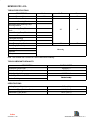
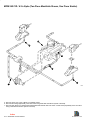
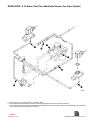
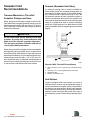
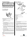
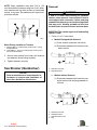
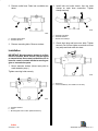
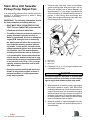
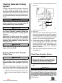
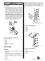
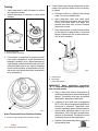
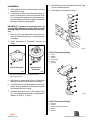
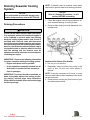
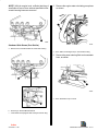
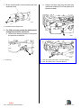
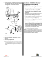
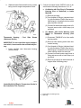
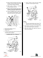
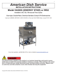
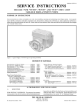
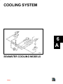
COOLING SYSTEM
6
A
22381
SEAWATER COOLING MODELS
Index
Table of Contents
Page
MCM 262 CID / 4.3L Alpha (Two Piece
Manifolds Shown, One Piece Similar) . . . . 6A-2
MCM 262CID / 4.3L Bravo (Two Piece
Manifolds Shown, One Piece Similar) . . . . 6A-3
Seawater Inlet Recommendations . . . . . . . . . . 6A-4
Transom Mounted or Thru-Hull Seawater
Pickups and Hose . . . . . . . . . . . . . . . . . . . . . 6A-4
Seacock (Seawater Inlet Valve) . . . . . . . . . . 6A-4
Sea Strainer . . . . . . . . . . . . . . . . . . . . . . . . . . 6A-4
Seawater Pickups . . . . . . . . . . . . . . . . . . . . . . . . 6A-5
Thru-Hull Mounted . . . . . . . . . . . . . . . . . . . . . 6A-5
Transom Mounted . . . . . . . . . . . . . . . . . . . . . 6A-5
Sea Strainer (Quicksilver) . . . . . . . . . . . . . . . . . 6A-6
Removal . . . . . . . . . . . . . . . . . . . . . . . . . . . . . 6A-6
Installation . . . . . . . . . . . . . . . . . . . . . . . . . . . . 6A-7
Stern Drive Unit Seawater Pickup Pump
Output Test . . . . . . . . . . . . . . . . . . . . . . . . . . . . . 6A-8
Stern Drive Unit Seawater Pickup Pump
Repairs . . . . . . . . . . . . . . . . . . . . . . . . . . . . . . . . . 6A-9
Water Circulating Pump Replacement . . . . . . . 6A-9
Removal . . . . . . . . . . . . . . . . . . . . . . . . . . . . . 6A-9
Cleaning and Inspection . . . . . . . . . . . . . . . . 6A-9
Installation . . . . . . . . . . . . . . . . . . . . . . . . . . . . 6A-9
Flushing Seawater Cooling System . . . . . . . . 6A-10
Engines with Stern Drive Seawater
Pickup Pump . . . . . . . . . . . . . . . . . . . . . . . . 6A-10
Check/Clean Seawater Strainer . . . . . . . . 6A-10
Thermostat . . . . . . . . . . . . . . . . . . . . . . . . . . . . . 6A-11
Removal . . . . . . . . . . . . . . . . . . . . . . . . . . . . 6A-11
Testing . . . . . . . . . . . . . . . . . . . . . . . . . . . . . . 6A-12
Installation . . . . . . . . . . . . . . . . . . . . . . . . . . . 6A-13
Draining Seawater Cooling System . . . . . . . . 6A-14
Draining Precautions . . . . . . . . . . . . . . . . . . 6A-14
Auxiliary Hot Water Heater Installation
Information . . . . . . . . . . . . . . . . . . . . . . . . . . . . 6A-17
Index
6A-0 - SEAWATER COOLED MODELS
90-823226--1 996
MCM 262 CID / 4.3L
TORQUE SPECIFICATIONS
DESCRIPTION
Alternator Brace to Alternator
Lb. In.
Lb. Ft.
N⋅m
192
28
Alternator Brace to Block
Alternator to Mounting Bracket
Alternator/Power Steering Pump
Mounting Bracket
Power Steering Pump Brace to
Block
30
41
20
27
Power Steering Pump Bracket
Thermostat Cover
Thermostat Housing
Water Circulating Pump
Water Temperature Sender
Drain Plugs (See Note)
Hose Clamps
Securely
S
l
Petcocks
Pulleys
Note: Coat threads with Quicksilver Perfect Seal before installing.
TOOLS/LUBRICANTS/SEALANTS
DESCRIPTION
Quicksilver Perfect Seal
Quicksilver Flushing Attachment
Quicksilver Liquid Neoprene
Loctite Pipe Sealant with Teflon
Marine Caulking
PART NUMBER
92-34227-1
73971A2
92-25711--2
Obtain Locally
SPECIFICATIONS
Cooling System Capacity
15 Qts (14L)
Thermostat (Type) Stainless Steel
160° F (71° C)
Thermostat (Type) Brass
143° F (60° C)
Index
90-823226--1 996
SEAWATER COOLED MODELS - 6A-1
MCM 262 CID / 4.3L Alpha (Two Piece Manifolds Shown, One Piece Similar)
b
c
b
c
c
a
74816
a - Remove Hoses (Lift, Lower or Bend To Completely Drain).
b - Remove Block Plugs (Repeatedly Clean Out Holes Using A Stiff Wire Until Entire System Is Drained).
c - Remove Drain Plugs From Exhaust Exhaust Manifold Drain Elbows and Fuel Cooler or Water Tube (Repeatedly Clean Out Holes
Using A Stiff Wire Until Entire System Is Drained)
Index
6A-2 - SEAWATER COOLED MODELS
90-823226--1 996
MCM 262CID / 4.3L Bravo (Two Piece Manifolds Shown, One Piece Similar)
b
c
a
b
c
a
c
74818
a - Remove Hoses (Lift, Lower or Bend To Completely Drain).
b - Remove Block Plugs (Repeatedly Clean Out Holes Using A Stiff Wire Until Entire System Is Drained).
c - Remove Drain Plugs From Exhaust Exhaust Manifold Drain Elbows and Fuel Cooler or Water Tube (Repeatedly Clean Out Holes
Using A Stiff Wire Until Entire System Is Drained)
Index
90-823226--1 996
SEAWATER COOLED MODELS - 6A-3
Seawater Inlet
Recommendations
Transom Mounted or Thru-Hull
Seawater Pickups and Hose
Water pickup must be large enough to permit sufficient water flow to engine seawater pickup pump for
adequate engine cooling [30 gal. per min. (114 L per
min.) minimum]. Pickup also must supply a positive
head while underway.
Seacock (Seawater Inlet Valve)
If a seacock is being used, it must be installed between water pickup and seawater pickup pump (or
sea strainer), to allow operator to shut off the seawater in case of a leak or when boat is not in use. This
will allow the operator to flush or drain the engine, or
clean the sea strainer while boat is in the water. Seacock used must have an internal cross-sectional area
equal to or greater than hose to prevent restricting
water flow. Install seacock in an area where it will be
easily accessible and self-supporting to prevent hose
fatigue.
a
! CAUTION
Do not install water pickup directly in line with
propeller, as pickup may create turbulence and
allow air to flow into the “propeller slipstream.”
This will cause propeller ventilation and will adversely affect boat performance.
Water pickup should be located as close to seawater
pickup pump inlet as possible and in an area where
an uninterrupted, solid stream of water will flow past
when boat is underway. Connect water pickup to seawater pickup pump inlet with 1-1/4 in. (32 mm) I.D.
wire reinforced hose of adequate wall thickness to
prevent it from collapsing from pump suction. Be sure
to secure hose connections with hose clamps.
b
d
c
70355
Seacock (With Thru-Hull Pickup Shown)
a - Hose Connector [1-1/4 In. (32mm) I.D.] to Seawater Pump
Inlet
b - Seacock [1-1/4 In. (32mm)] Brass Ball or Gate Valve
c - Seawater Pickup
d - Direction of Seawater Flow
Sea Strainer
If boat is equipped with a sea strainer, it must be of
sufficient size to ensure that an adequate supply of
water is maintained for engine cooling. Install seawater strainer in an area where it will be easily accessible for inspection and cleaning. Strainer should be installed in water inlet hose after water inlet valve to
allow operator to shut off water when cleaning strainer.
Index
6A-4 - SEAWATER COOLED MODELS
90-823226--1 996
Transom Mounted
Seawater Pickups
NOTICE
Refer to manufacturer’s instructions for information on removal and installation of
other than Quicksilver Seawater Pickups.
(Quicksilver Part Number: 88845A1)
a
b
c
d
e
f
IMPORTANT: Seal the inside edges of any hole
made through the hull with a suitable sealant to
prevent water absorption and deterioration.
g
Thru-Hull Mounted
h
(Quicksilver 68670A2)
i
b
J
d
72640
c
a
Seawater Pickup Installation
72639
Quicksilver Thru-Hull Seawater Pickup Shown
a - Seawater Pickup
b - Seawater Inlet Slot (MUST Face Forward - Parallel with
Water Flow
c - Mounting Screw Holes (If So Designed)
d - Nut
1. Seal inside edges of 1-3/4 in. (44 mm) hole in hull
using a suitable sealer.
a
b
c
d
e
f
g
h
i
j
-
Hose Nipple
Nuts (4)
Gasket - Between Pickup and Transom
O-Ring (4)
Washer (4)
Screw (4)
Plastic Plug
Pickup
Screen
Screw
1. Seal the inside edges of the 1-1/2 in. (38 mm)
hole for hose nipple.
2. Apply marine caulking (sealer) to mounting surface on seawater pickup where hull contact will
occur when installed.
2. Be certain hose nipple and plastic plug are in
place and threads have been sealed with Loctite
Pipe Sealant with Teflon prior to tightening each
securely.
3. Ensure slots in seawater pickup are facing forward (toward bow of boat) and install seawater
pickup through hull. The slots must be parallel
with flow of water.
3. Position one flat washer and one rubber O-ring
on each 5/16 in. x 4 in. (102 mm) long, round head
screw as shown. Coat each screw shaft with silicone sealant or equivalent.
4. Fasten pickup with four appropriate mounting
screws (if so designed).
4. Place new gasket on pickup housing and hold
pickup in place on transom. Install four round
head screws (with washers and O-rings in place)
into pickup mounting holes and through drilled
21/64 in. (8.5 mm) holes in transom.
5. Apply marine caulking as needed inside boat.
Apply Loctite to threads of nut and install on pickup on inside of boat and torque nut to 35 lb. ft. (42
N•m).
NOTE: If pickup being used does not have mounting
screws on underside where mounted to hull, be certain, after nut is torqued, that slots are still facing forward.
Index
90-823226--1 996
SEAWATER COOLED MODELS - 6A-5
NOTE: Some installations may have 7/32 in. (5.5
mm) holes drilled in transom using four 5/16 in. diameter stainless steel lag bolts in place of round head
screws. In any case, flat washers and O-rings are required as outlined.
a
b
Removal
! CAUTION
If boat is in water while working on seawater
strainer, close seacock, if so equipped. If boat is
not equipped with a seacock, remove and plug
seawater inlet hose to prevent a siphoning action
that may occur, allowing seawater to flow from
the drain holes or removed hoses and enter boat.
IMPORTANT: Be certain engine is off and cooling
system is cold.
1. Follow “a” or “b” instructions:
72641
a. Models Equipped with Seacock:
(1) Close seacock (seawater inlet valve).
Water Pickup Installed on Transom
(2) Disconnect seawater inlet hose from seawater strainer.
a - Diagonal Mount - Leading Edge of Pickup 1/8 In. (3mm)
from Boat Bottom
b - Vertical Mount - Corner of Leading Edge of Pickup 1/8 In.
(3mm) from Boat Bottom
5. Secure water pickup from inside with locknuts
and washers (unless using lag bolts).
6. Tighten fasteners securely.
a
b
72691
Sea Strainer (Quicksilver)
a - Seawater Inlet Hose
b - Seawater Strainer
NOTICE
Refer to manufacturer’s instructions for information on removal and installation of
other than Quicksilver Sea Strainer.
b. Models without Seacock:
(1) Disconnect seawater inlet hose from seawater strainer inlet and plug seawater inlet hose.
b
a
b
c
d
-
c d
a
70062
Seawater Inlet Hose
Seawater Strainer
Seawater Strainer Inlet
Plug
Index
6A-6 - SEAWATER COOLED MODELS
90-823226--1 996
2. Remove outlet hose. Drain into a suitable container.
a
2. Install inlet and outlet hoses. Use two hose
clamps on each hose connection. Tighten
clamps securely.
c
c
a
b
b
72645
72643
a - Seawater Inlet Hose
b - Seawater Strainer
c - Double Hose Clamps
a - Seawater Outlet Hose
b - Seawater Strainer
3. Check drain plug and lens cover bolts. Tighten
securely. Do not over-tighten cover bolts or cover
may warp and leak water into boat.
3. Remove mounting bolts. Remove strainer.
Installation
b
IMPORTANT: Mount seawater strainer in a vibration-free location. Never mount it on the engine
or transmission. Hoses must not be kinked or allowed to come in contact with hot or moving engine or transmission parts.
1. Mount seawater strainer (Arrow must point toward seawater pump.)
a
Tighten mounting bolts securely.
72644
b
a - Drain Plug
b - Lens Cover Bolt (2, One Hidden in This View)
a
c
c
72644
a - Seawater Strainer
b - Arrow
c - Mounting Bolt Hole Location (Bolts Not Shown)
Index
90-823226--1 996
SEAWATER COOLED MODELS - 6A-7
Stern Drive Unit Seawater
Pickup Pump Output Test
If an overheating problem exists, use this test to determine if a sufficient amount of water is being
supplied to cool engine.
IMPORTANT: The following information should
be observed before proceeding with test:
1. Remove water inlet hose, which runs between
gimbal housing water tube and engine, and replace with another hose of same diameter, but
approximately 3 ft. (1 m) longer. Hose should be
wire reinforced or of adequate wall thickness to
prevent it from kinking when performing test.
Clamp hose at gimbal housing water tube only.
Do not clamp hose at engine end.
• BOAT MUST BE IN THE WATER FOR THIS
TEST. This test CANNOT BE performed with
a flush-test device and water hose.
• The ability of this test to detect a problem is
greatly dependent upon the accuracy in
which it is performed. An error in setting the
engine RPM, timing the test or measuring
the water output will affect the overall accuracy of the test and may produce misleading results. To help ensure accurate results,
a shop tachometer with an error of less than
5% should be used. The boat tachometer
definitely should not be used as its accuracy is questionable. A stop watch should be
used to time the duration of the test to help
ensure that the accuracy is maintained within one second. An 8 U.S.qt. (7.6 L) or larger
capacity container should be used to measure water output.
• Due to the manner in which this test is performed, it may not be possible to detect a
marginal condition or a high-speed water
pump output problem.
c
a
b
72614
a - Water Tube
b - Hose Clamp
c - Water Hose
2. Place an 8 U.S. qt. (7.6 L) or larger container near
unclamped end of hose.
! CAUTION
Do not run engine for more than 15 seconds with
hose disconnected, in next step, as internal damage to engine and exhaust system may result.
3. With assistance of another person, start engine
and adjust speed to exactly 1000 RPM while
holding unclamped end of hose on connection on
engine. Remove hose from connection on engine
and direct water flow into container for exactly 15
seconds. At the end of 15 seconds, direct the water flow overboard, return engine to idle and stop
engine. Reconnect hose to engine.
4. Measure quantity of water discharged into container and compare with specifications given in
chart following.
Index
6A-8 - SEAWATER COOLED MODELS
90-823226--1 996
5. Repeat test four times to check repeatability of
results.
5. Remove pump pulley attaching bolts, lockwashers, clamping ring (if so equipped) and pulley.
6. Disconnect hose(s) from pump.
Alpha Stern Drive Pump Output
for 15 Second Period
Drive Unit Gear Ratio
Minimum Quantity
U.S. Qts. (L)
1.98:1
3.0 (2.8)
1.84:1
3.3 (3.1)
1.65:1
3.6 (3.4)
1.50:1
4.0 (3.8)
1.32:1
4.5 (4.3)
Stern Drive Unit Seawater
Pickup Pump Repairs
NOTICE
MCM (Stern Drive) Models equipped with
Alpha Drive Units have a seawater pickup
pump mounted in stern drive unit. Refer to
appropriate Stern Drive Service Manual for
further testing and repairs.
Water Circulating Pump
Replacement
Removal
1. Drain water from cylinder block. Refer to “Draining Seawater Cooling System” as outlined later in
this section.
2. Loosen circulating pump pulley attaching bolts.
Do not remove bolts at this time.
3. Loosen power steering pump brace and pump
mounting bolts, then pivot pump inward and remove drive belts.
7. Remove bolts, which secure pump to cylinder
block, and remove pump and old gaskets (discard gaskets).
Cleaning and Inspection
1. Clean gasket surfaces on water pump and cylinder block.
2. Inspect water pump for blockage, cracks, sand
holes, corrosion or other damage. Inspect pump
impeller for cracks and erosion. Replace complete pump if any damage exists.
3. Check impeller shaft and bearings for excessive
side play. If play can be felt, replace complete
pump.
4. Inspect pump pulley for bends, cracks, corrosion
or other physical damage. Inspect pulley for rotational trueness. Replace pulley if damaged or untrue.
Installation
1. Coat both sides of new circulating pump gasket
with Quicksilver Perfect Seal, then position gaskets and circulating pump on cylinder block. Coat
threads of circulating pump attaching bolts with
Quicksilver Perfect Seal and install bolts and alternator brace (if applicable). Torque bolts to
specifications.
2. Reconnect hoses to pump.
3. Install pump pulley and clamping ring (if used) on
pump hub and secure with bolts and lockwashers. Tighten bolts securely.
4. Install drive belts and adjust tension as outlined
in “Drive Belt Tension Adjustment.”
5. Start engine and check for leaks.
4. Loosen alternator brace attaching bolts and alternator mounting bolt, then pivot alternator inward
and remove drive belt.
Index
90-823226--1 996
SEAWATER COOLED MODELS - 6A-9
Flushing Seawater Cooling
System
2. Connect hose between flushing attachment and
water tap.
If engine is operated in salty, polluted or mineral-laden waters, seawater cooling system should be
flushed periodically (preferably after each use) with
fresh water to reduce corrosion and prevent the accumulation of deposits in the system. Seawater cooling system also should be thoroughly flushed prior to
storage.
! WARNING
When flushing, be certain the area around propeller is clear, and no one is standing nearby. To
avoid possible injury, remove propeller.
a
b
! CAUTION
Do not run engine above 1500 RPM when flushing. Suction created by seawater pickup pump
may collapse flushing hose, causing engine to
overheat.
IMPORTANT: If cooling system is to be flushed
with boat in the water, seacock (if so equipped)
must be closed, or water inlet hose must be disconnected and plugged to prevent water from
flowing into boat.
! CAUTION
Watch temperature gauge at dash to ensure the
engine does not overheat.
Engines with Stern Drive Seawater
Pickup Pump
! CAUTION
To prevent engine or stern drive unit damage DO
NOT run engine or drive unit without water being
supplied to water intake openings on gear housing.
If flushing cooling system with boat in water, raise
drive unit to trailer position, install flushing attachment and lower drive unit to full IN/DOWN position.
1. Install Quicksilver Flushing Attachment (or equivalent) over water intake openings in gear housing.
72672
a - Quicksilver Flushing Attachment
b - Garden Hose
3. With drive unit in normal operating position, partially open water tap (about 1/2 maximum) and allow cooling system to fill completely. Cooling system is full when water is discharged through the
propeller. Do not use full tap water pressure.
4. Place remote control in NEUTRAL, idle speed
position and start engine. Operate engine at idle
speed, in NEUTRAL, for about 10 minutes, or until discharge water is clear. Watch temperature
gauge on instrument panel to ensure that engine
does not overheat.
5. Stop engine. Shut off tap water and remove flushing attachment
Check/Clean Seawater Strainer
NOTICE
Refer to manufacturer’s instructions for information on checking and cleaning of other than Quicksilver Seawater Strainer.
1. Visually inspect seawater strainer through glass
top.
! WARNING
When cleaning seawater strainer, close seacock,
if so equipped. If boat is not equipped with a seacock, remove and plug seawater inlet hose to
prevent a siphoning action that may occur, allowing seawater to flow from the drain holes or removed hoses.
Index
6A-10 - SEAWATER COOLED MODELS
90-823226--1 996
! CAUTION
Do not over-tighten cover screws or cover will
warp and leak.
2. With engine off, close seacock, if so equipped, or
remove and plug seawater inlet hose, if no seacock exists. Remove two screws and washers,
and cover. Remove strainer, and drain plug and
washer. Clean any debris from strainer housing;
flush both strainer and housing with clean water.
Check gasket; replace when necessary (if it
leaks). Reinstall strainer, drain plug and washer.
Reattach cover with screws and washers. Open
seacock, or unplug and reconnect seawater inlet
hose. Tighten hose clamps securely. After starting engine, check for leaks and/or air in system,
which would indicate an external leak.
b
NOTE: If equipped with a lifting eye (not shown in following), note placement of lifting eye so that it may be
positioned exactly the same upon installation , or it
may interfere with the fit of the flame arrestor cover.
a
b
c
d
e
f
a
c
d
72589
6 Hose Thermostat Housing
a
b
c
d
e
f
e
h
f
-
Cover
Gasket
Spacer
Thermostat
O-Ring
Housing
g
a
72673
Quicksilver Seawater Strainer Shown
a
b
c
d
e
f
g
h
-
b
Screws and Washers
Cover
Glass
O-Ring
Strainer
Housing
Drain Plug and Sealing Washer
Gasket
c
d
e
71758
Thermostat
Removal
1. Drain water from cylinder block and exhaust
manifolds.
2. Remove thermostat cover attaching bolts and
lockwashers, then remove cover and gasket.
4 Hose Thermostat Housing
a
b
c
d
e
-
Housing
O-Ring
Thermostat (Stainless Steel)
Spacer
Gasket
3. Remove thermostat from thermostat housing or
cover.
Index
90-823226--1 996
SEAWATER COOLED MODELS - 6A-11
Testing
1. Clean thermostat in soap and water to remove
any deposits or debris.
2. Inspect thermostat for corrosion or other visible
damage.
b
a
4. Check opening and closing temperature of thermostat (using a tester similar to the one shown)
as follows:
a. Fill tester to within 1 in. (25mm) of top with tap
water. Do not use distilled water.
b. Open thermostat valve and insert nylon
string. Position thermostat on string so that it
will be just below water level when suspended, then allow valve to close. Suspend
thermostat in water.
c. Place thermometer in container and position
so that bottom of thermometer is even with
bottom of thermostat. Do not allow thermometer to touch container.
a
72674
b
71801
a - Brass Thermostat
b - Stainless Steel Thermostat
3. If thermostat is suspected of producing insufficient engine temperature, check thermostat for
leakage by holding it up to a lighted background.
Light leakage around the thermostat valve indicates that thermostat is not closing completely
and should be replaced. (A small amount of leakage at one or two points around the valve perimeter is acceptable.)
c
72675
a - Thermometer
b - Nylon String
c - Thermostat (Typical)
IMPORTANT: When performing procedures
“d”-“f,” water must be agitated thoroughly to obtain accurate results.
d. Plug in tester and observe temperature at
which thermostat opens (thermostat drops off
thread). Thermostat must open at specified
temperature stamped on thermostat.
e. Continue to heat water until a temperature
25°F (14°C) above temperature specified on
thermostat is obtained. Thermostat valve
must be completely open at this temperature.
a
72717
Brass Thermostat Shown (Stainless Similar)
a - Check for Light Leakage Around Perimeter of Valve
f.
Unplug tester and allow water to cool to a
temperature 10°F (5°C) below specified temperature on thermostat. Thermostat must be
completely closed at this temperature.
g. Replace a thermostat that fails to meet all of
the preceding tests.
Index
6A-12 - SEAWATER COOLED MODELS
90-823226--1 996
Installation
1. Clean gasket surfaces on thermostat cover and
thermostat housing.
8. Reconnect hose(s) to thermostat housing. Tighten hose clamps securely.
9. Start engine and inspect for leaks.
2. If thermostat housing was disturbed during removal of thermostat, remove thermostat housing. Clean gasket surfaces on thermostat housing and intake manifold and replace thermostat
housing-to-intake manifold gasket.
a
b
c
d
IMPORTANT: If gasket has continuity rivets, do
not coat with Quicksilver Perfect Seal, or audio
warning temperature switch may not work properly.
e
f
3. Place O-ring in the thermostat housing. Be certain it is positioned properly on mounting flange
in housing.
4. Install thermostat in thermostat housing as
shown.
72589
6 Hole Thermostat Housing
a
b
c
d
e
f
a
b
Brass Thermostat
Stainless Steel
Thermostat
72674
-
Cover
Gasket
Spacer
Thermostat
O-Ring
Housing
a
71801
a - Install Thermostat With This End (Down) Toward
Thermostat Housing
b
5. Align tang on sleeve with groove in thermostat
housing bore and install sleeve into housing.
c
6. Coat both sides of new thermostat cover-to-thermostat housing gasket with Quicksilver Perfect
Seal and position on housing.
d
e
7. Reinstall thermostat cover (with engine lifting
eye, if so equipped) and torque screws with lockwashers to 30 lb. ft. (41 N·m).
71758
4 Hole Thermostat Housing
a
b
c
d
e
-
Housing
O-Ring
Thermostat (Stainless Steel)
Spacer
Gasket
Index
90-823226--1 996
SEAWATER COOLED MODELS - 6A-13
Draining Seawater Cooling
System
NOTICE
For cold weather or extended storage information and procedures, refer to SECTION 1B.
NOTE: If possible, place a container under drains
and hoses to prevent water from draining into boat.
NOTICE
Refer to “Draining Precautions,” in this
section, BEFORE proceeding.
1. Check that engine is as level as possible to ensure complete draining of cooling system.
Draining Precautions
2. Remove drain plugs (port and starboard) from
cylinder block.
! CAUTION
If boat is in the water, seacock (water inlet valve),
if so equipped, must be left closed until engine is
to be restarted to prevent water from flowing
back into cooling system and/or boat. If boat is
not fitted with a seacock, water inlet hose must
be left disconnected and plugged to prevent water from flowing back into cooling system and/or
boat. As a precautionary measure, attach a tag to
the ignition switch or steering wheel of the boat
with the warning that the seacock must be
opened or the water inlet hose reconnected prior
to starting the engine.
IMPORTANT: Observe the following information
to ensure complete draining of cooling system.
• Engine must be as level as possible.
• A wire should be repeatedly inserted into all
drain holes to ensure there are no obstructions in passages.
IMPORTANT: To prevent threads in manifolds, elbows and cylinder blocks from rusting out during storage, reinstall plugs using Quicksilver
Perfect Seal on threads. Never leave drain plugs
out during storage.
a
72993
Starboard Side Shown (Port Similar)
a - Drain Plug (Port and Starboard)
3. Repeatedly clean out drain holes using a stiff
piece of wire. Do this until entire system is
drained.
NOTE: It may be necessary to lift, bend, or lower
hoses to allow water to drain completely when hoses
are disconnected.
4. Remove hose or drain plug from bottom of port
and starboard manifolds.
Index
6A-14 - SEAWATER COOLED MODELS
90-823226--1 996
NOTE: With the engine level, sufficient draining of
manifolds will occur when exhaust manifold-to-thermostat housing hoses are removed.
5. Remove the engine water circulating pump hose
as shown.
a
a
72993
72587
Starboard Side Shown (Port Similar)
a - Bottom Hose, Exhaust Manifold to Thermostat Housing
a - Hose, Water Circulating Pump to Thermostat Housing
6. Remove the power steering fluid cooler seawater
hose, as shown.
b
a
72588
a - Hose, Seawater Pump to Cooler
c
b - Drain Plug in Exhaust Manifold Elbow
c - Later Models Are Equipped With This Style Of Drain Plug.
Index
90-823226--1 996
SEAWATER COOLED MODELS - 6A-15
7. Bravo models need to remove both hoses form
seawater pump.
a
b. Remove the drain plug from the water tube
(carburetor models) or Cool Fuel system (fuel
injection models)
71170
a - Seawater Inlet And Outlet Hoses
8. For 1996 and newer models the additional following steps must be performed:
a. Remove the drain plug from the Y-fitting form
the port side of the block.
a
75081
a
b
a - Drain Plug
75018
a - Drain Plug (Cool Fuel System - Fuel Cool System)
b - Drain Plug (Water Tube - Carburetor Models)
Index
6A-16 - SEAWATER COOLED MODELS
90-823226--1 996
9. Insert a small wire (repeatedly) to make sure that
vent holes and water drain holes and passages
(as shown) are unobstructed and open.
e
Auxiliary Hot Water Heater
Installation Information
IMPORTANT: When connecting a cabin heater or
hot water heater, certain requirements must be
met.
• Supply hose (from engine to heater) and return hose (from heater to engine) MUST
NOT EXCEED 5/8 in. (15.8 mm) I.D. (inside
diameter).
b
• Make heater connections ONLY at locations
described in the following instructions.
d
• Check complete system for leaks after heater is connected into cooling system.
f
a
• Check for overheating condition (of engine)
after heater is connected.
c
71216
1. Hot water heater supply hose can be connected
at several different locations. On some models,
there may be other accessories and options that
are using these hot water supply locations. One
of the following should be available for use when
connecting the hot water heater system.
a. Port side of thermostat housing.
f
NOTE: On some models it may be necessary to remove the audio warning heat switch from port side of
thermostat housing and reposition to water circulating pump opening as outlined following.
c
70134
a
b
c
d
-
Speedometer Pitot Tube
Trim Tab Cavity Vent Hole
Trim Tab Cavity Drain Passage
Gear Housing Water Drain Hole (One Each - Port and
Starboard
e - Gear Housing Cavity Vent Hole
f - Gear Housing Cavity Drain Hole
10. After cooling system has been drained completely, install and tighten securely all drain plugs. Reconnect all hoses and tighten all hose clamps securely.
Index
90-823226--1 996
SEAWATER COOLED MODELS - 6A-17
b. Starboard side of thermostat housing, unless
being used for engine temperature switch.
2. Connect hot water heater SUPPLY hose to desired location following instructions “a” or “b”:
a. On Models with Pipe Plug in Thermostat
Housing (Port or Starboard) or Intake
Manifold:
(1) Remove pipe plug.
(2) Coat threads of fitting(s) (obtained locally) with Quicksilver Perfect Seal and install fitting(s) in threaded hole from which
pipe plug was removed.
(3) Connect hot water heat supply hose to fitting and secure with a hose clamp (not
provided).
72613
b. On Models with Audio Warning Heat
Switch in Thermostat Housing (Port
Side):
Shown
(1) Disconnect TAN/BLUE wire from audio
warning switch.
IMPORTANT: Do not reposition engine temperature switch, it must remain where installed by factory.
(2) Remove audio warning switch from thermostat housing.
Thermostat Housing
(Starboard Similar)
-
Port
Side
c. Intake manifold near thermostat housing
(some models).
(3) Coat threads of fitting(s) (obtained locally) with Quicksilver Perfect Seal and install fitting(s) in threaded hole from which
audio warning switch was removed.
(4) Connect hot water heater supply hose to
fitting and secure with a hose clamp (not
provided).
(5) Remove pipe plug from starboard side of
engine water circulating pump.
a
72708
Intake Manifold (If Engine Temperature Sender is
Not Installed at This Location)
b
72702
a - Engine Water Circulating Pump
b - Pipe Plug
Index
6A-18 - SEAWATER COOLED MODELS
90-823226--1 996
(6) Apply Loctite Pipe Sealant with Teflon to
threads of reducer bushing (obtain locally) and audio warning heat switch.
b. Secure T-fitting in hose with hose clamps
(provided in kit) and tighten securely.
(7) Install reducer bushing in circulating
pump and tighten securely.
a
(8) Apply Loctite Pipe Sealant with Teflon to
threads of audio warning switch and install in reducer bushing. Tighten securely.
(9) Connect TAN/BLUE wire to switch and
secure with nut and lockwasher. Coat terminal with Quicksilver Liquid Neoprene.
a
c
b
72705
Typical
a - T-Fitting
c. Connect hot water heater return hose to T-fitting and secure with hose clamp (provided).
72703
4. Secure hoses, as required, to ensure they do not
rub or chafe against engine components.
5. With boat in water, start engine and check for
leaks and overheating.
a - Reducer Bushing (Hidden in this View)
b - Audio Warning Heat Switch
c - TAN/BLUE WIre
3. Connect hot water heater return hose into system
as follows (refer to figures):
a. Cut approximately 3/4 in. (19 mm) out of hose
to maintain proper hose configuration.
a
72704
Typical
a - Cut Here
Index
90-823226--1 996
SEAWATER COOLED MODELS - 6A-19
THIS PAGE IS INTENTIONALLY BLANK TO
ALLOW FOR CORRECTIONS OR ADDITIONS
AT A LATER DATE
Index
6A-20 - SEAWATER COOLED MODELS
90-823226--1 996