1
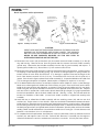
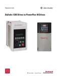
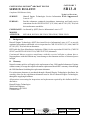
CATEGORY 3
CONTINENTAL MOTORS® AIRCRAFT ENGINE
SB13-8
SERVICE BULLETIN
Compliance Will Enhance Safety
Te chn ical Port ions
SUBJECT:
Hartzell Engine Technologies Service Information FA A A p p ro ve d
Letter A-137
PURPOSE:
Provides alternator continued airworthiness instructions and brush service
instructions for the CMI P/N 655997 (12V, 60A) and 657199 (24V, 70A) belt
driven alternator assemblies
COMPLIANCE: As directed by (HET) Service Information Letter A-137
MODELS
AFFECTED:
I.
IOF-240-B, IO-550-N, IOF-550-N, TSIO-550-K, TSIOF-550-D
Background:
Hartzell Engine Technologies (HET) has issued Service Information Letter A-137 to provide
continued airworthiness and brush service inspection for CMI P/N 655997 (12V, 60A) and P/N
657199 (24V, 70A) belt driven alternators.
HET holds the Parts Manufacture Authority (PMA) for the equivalent ES-6012-6 (CMI P/N
655997) and ES7024-2014/01/1514 (CMI P/N 657199) alternators.
Continental Motors requires compliance with this service bulletin as shown above.
Noncompliance with this bulletin may cause damage to the alternator and loss of electrical power
in flight.
II.
Warranty
Normal warranty policies will apply to the replacement of any CMI supplied alternators. Engines
within warranty coverage that require alternator replacement should file a warranty claim through
the CMI distributor furnishing the replacement alternator.
If a replacement alternator is purchased through a Hartzell Engine Technologies distributor, the
warranty claim for the replacement alternator must be filed to Hartzell Engine Technologies,
through the supplying distributor.
All questions concerning the inspections and replacement required by this bulletin shall be
directed to:
Hartzell Engine Technologies
2900 Selma Highway
Montgomery, AL 36108
1-888-461-6077
ISSUED
REVISED
2014/01/15
---
©2013 Continental Motors, Inc.
PAGE NO
1 of 1
SB13-8
P.O. Box 90 Mobile, AL 251-436-8299
REVISION
---
Service
Information L etter
2900 Selma Highway
Montgomery, AL 36108 USA
Tel: 334-386-5400 Fax: 334-386-5450
Letter No. A-137
Issue Date: March 9, 2011
ES-6012-6 & ES-7024-11 & -14 Alternators
Continued Airworthiness (ICA)
& Brush Service Instructions
INTRODUCTION:
Hartzell Engine Technologies, LLC (HET), formerly Kelly Aerospace Energy Systems, LLC (KAES),
alternators ES-6012-6 & ES-7024-11 & -14 are recent designs coming into the general aviation market. HET
is issuing this SIL to provide basic continued airworthiness instruction (ICA) for the ES-6012-6 & ES-7024-11
& -14 alternators as used on certified engines or aircraft. Basic continued airworthiness consists of required
periodic inspections, general troubleshooting, and brush inspection and/or replacement instruction. At this
time, any condition beyond the scope of this publication requires replacement of the alternator.
This Service Information Letter provides instruction for continued airworthiness of the alternator and consists of
periodic inspection requirements, general troubleshooting, and, if necessary, instruction for removing, inspecting,
and replacing the brush assembly in ES-6012-6 & ES-7024-11 & -14 alternators.
COMPLIANCE:
At each annual inspection not to exceed the applicable time in service requirement of periodic inspection
Chart 1 - and/or - any time it is necessary to inspect or replace the alternator brushes on an ES-6012-6 or
ES-7024-11 or -14 alternator.
EFFECTIVITY:
All Hartzell Engine Technologies, formerly Kelly Aerospace Energy Systems, LLC, ES-6012-6 & ES-7024-11
or ES-7024-14 alternators when used on Type Certificated aircraft or engines. They are currently used on
specific Teledyne Continental Motors series, IOF-240 (ES-6012-6) and IO-550 and IOF-550 (ES-7024-11 &
ES-7024-14) engines.
PROCEDURE:
Inspection: (See Chart 1)
WARNING::
THE ALTERNATOR WHEN MOUNTED ON AN AIRCRAFT, PRESENTS A PHYSICAL
HAZARD FROM PROPELLERS AND ROTATING DEVICES.
THE ALTERNATOR
PRODUCES A HIGH ELECTRICAL CURRENT OUTPUT WHICH PRESENTS AN
ELECTRICAL SHOCK HAZARD, THAT CAN RESULT IN SERIOUS INJURY IF PROPER
SAFETY PROCEDURES ARE NOT FOLLOWED.
CAUTION::
DO NOT USE OBSOLETE OR OUTDATED INFORMATION. PERFORM ALL INSPECTIONS
OR WORK IN ACCORDANCE WITH THE MOST RECENT REVISION OF THE
APPLICABLE AIRCRAFT OR ENGINE MAINTENANCE MANUAL. INFORMATION
CONTAINED IN THE APPLICABLE MAINTENANCE MANUALS MAY BE SIGNIFICANTLY
CHANGED FROM EARLIER REVISIONS. USE OF OBSOLETE INFORMATION MAY
CREATE AN UNSAFE CONDITION THAT MAY RESULT IN DEATH, SERIOUS BODILY
INJURY, AND/OR SUBSTANTIAL PROPERTY DAMAGE. REFER TO THE APPLICABLE
AIRCRAFT OR ENGINE MAINTENANCE MANUAL INDEX FOR THE MOST RECENT
REVISION LEVEL OF THE OE-A2 MAINTENANCE MANUAL.
For questions concerning this instruction please contact HET, Service Dept. at (888) 461-6077. Contact your local HET
distributor to purchase available service parts.
Rev. New
Hartzell Engine Technologies SIL A-137
Page 1 of 7
PROCEDURE: (cont’d)
Inspection: (See Chart 1)
1. Determine if the airplane uses a ES-6012-6, ES-7024-11 or ES-7024-14 alternator. This may be done
by observing the equipment list, logbook, or other airframe or engine paperwork. If still undetermined,
it will be necessary to remove the cowling and observe the body of the alternator for the data tag.
2. If an ES-6012-6, ES-7024-11, or ES-7024-14 alternator is installed, the Periodic Inspections of
Chart 1 apply. (ES-6012-6 would be (12V) and the ES-7024-11 & -14 would be (24V).
3. Check the time in service on the unit and begin inspections at the nearest time interval and task.
For example, if the unit is new or recently overhauled, then start at the ten (10) hour inspection. If
the unit was installed prior to release of this SIL and has 100 hours, then start at this inspection and
so on. If the time is unknown perform the 500 hour inspection.
4. If the alternator is not an ES-6012-6 & ES-7024-11 & -14, proceed to Return to Service instruction 20.
5. For each inspection on Chart 1 requiring torque application, refer to Table 1, or the latest revision of
SIL A-125 Rev. A.
Troubleshooting: (See Chart 2)
6. Troubleshooting may help to determine the root cause and avoid unnecessary replacement of the
alternator. If there are conditions beyond those in the periodic inspection chart, refer to Chart 2
General Troubleshooting before attempting any repair or replacement the alternator.
7. Chart 2 lists the five symptoms common to these alternators. Choose the applicable symptom being
experienced and follow the trouble shooting advice beneath as applicable. For example, the
symptom is low or no alternator output. The possible cause could be loose terminal connections,
improper belt tension or worn brushes. After each cause a remedy is suggested.
8. The remedies suggested may require work on the alternator or work on the aircraft or engine.
Remember, if corrective action on the alternator is beyond tightening hardware or replacing the
brush holder assembly, the alternator must be replaced. In addition, if aircraft or engine work is
required, reference to the applicable service or maintenance manual will be required.
Brush inspection and/or replacement:
CAUTION:
BEFORE STARTING BRUSH INSPECTION OR REPLACEMENT, REFER
TO HET SERVICE INFORMATION LETTER SIL A125 REV. A. IT IS
MANDATORY THAT SIL A-125 REV. A OR LATEST BE COMPLIED WITH
PRIOR TO, OR IN CONJUNCTION WITH THIS SIL. FAILURE TO DO SO
MAY RESULT IN DAMAGE TO THE ALTERNATOR AND/OR AIRCRAFT.
9. Upon achieving each 500 hours time in service or any time the alternator brushes need to be
inspected or brush holder assembly replaced, the following instructions apply. (Depending upon the
reason for inspection or replacement, brush holder removal and installation may be done with
alternator on or off the aircraft engine.)
10. Assure all power is removed from the aircraft by disconnecting the battery and any ground power
source. Refer to Figure 1 & 2 to locate and remove the brush holder assembly. (See material required
section for brush holder assembly and hardware part numbers.)
11. To avoid the possibility of alternator damage, loosen the first and second nut of the battery terminal
(red insulator) prior to removing the back cover screws.
12. Disconnect the F1 (field) wire by removing hardware. Remove the three screws (3) and lock washers
(32) that hold the back cover (27) in place and remove the back cover.
Page 2 of 7
Hartzell Engine Technologies SIL A-137
Rev. New
PROCEDURE: (cont’d)
Brush inspection and/or replacement:
See Appendix for
Special Instructions
Regarding item 11
Brush Seal
Figure 1 Primary Locations
Figure 2 Brush Removal
CAUTION:
GREAT CARE MUST BE TAKEN WHEN REMOVING THE BRUSH HOLDER
ASSEMBLY AS THE BRUSHES ARE SPRING LOADED. THE BRUSHES
MAY FALL INTO THE ALTERNATOR OR POP OUT AND CHIP OR BREAK.
NEVER RE-USE DAMAGED BRUSHES AS THIS MAY LEAD TO
ALTERNATOR NOISE OR OUTPUT FAILURE.
13. Remove the two screws (35) and washers (32) that attach the brush holder assembly (7) to the slip
ring end housing. Remove the nut from the ground stud that secures the brush holder assembly
ground strap. Remove the brush holder assembly from the slip ring end assembly and inspect. If
replacing brush holder ass’y, discard the ass’y, lock washers and lock nuts.
14. Remove brushes from holder and mark to indicate removed position and orientation. Inspect brushes
for chipping or other damage including spring, cap, and wire. If damage appears to spring or there are
broken strands in brush lead, discard brush. If no damage is apparent, measure the length of the
brush. New brushes measure .5 inch (1.27 cm). To reuse the brush it must be .25 inch (.635 cm) or
greater. If less than this figure, replace brush holder assembly (7). Inspect the flexible brush holder seal
(11) for damage and replace as required. (Never replace a single brush, replace as a set only!)
15. If it is determined that the brushes are reusable, inspect the brush holder for cracks or other damage.
Never reuse a damaged brush holder even if the brushes are good. Place each brush into the brush
holder in the same position and orientation as removed. Place the orange rubber seal (11) over brush
holder using the seal special installation instructions in the appendix at the end of this SIL. Depress
each brush into it’s pocket with a small wood or plastic dowel and slip a length of 22 gage insulated wire
into the hole provided in side of the brush holder and seal. (See Fig. 2 inset.) The wire will retain the
brushes for installation of the holder. (A new brush holder assembly is shipped with retaining wire
installed.)
16. Install the new or refitted brush holder assembly with two retaining screws (35) and two new lock
washers (32). Torque screws to 18 to 20 in-lbs. Spin rotor and check for interference between the brush
holder and rotor. Remove the brush retaining wire allowing the brushes to snap into place. Reinstall the
brush holder ground strap to the ground stud and torque per Table 1. Measure the resistance between
the field (orange insulator) and ground terminal with an ohmmeter. Spin the pulley and note ohmmeter
reading. Meter should read between 5.8 and 20 ohms while rotor is turning for a 24 volt alternator and
between 2.8 and 20 ohms for a 12 volt alternator.
17. To complete the brush replacement, install the back cover (27) with three screws (3) and three new lock
washers (32) and torque to 20 to 25 in-lbs. Reinstall the alternator if removed per the engine or
airframe manufacturer’s service or maintenance instructions or manuals. Use only the latest revision.
Rev. New
Hartzell Engine Technologies SIL A-137
Page 3 of 7
PROCEDURE: (cont’d)
Torquing Hardware:
Note:
For more detail on hardware stacking and torque, please refer to the latest
revision of HET SIL A125 Rev. A. See caution note on page 2.
18. When hardware is replaced (nuts, screws, etc.) be sure to use an appropriate torque tool properly
calibrated for the task. Follow the torque settings recommended on Table 1 for all hardware that is part
the alternator. Hardware which retains aircraft terminals must be torqued to the specification called out
by the engine or airframe manufacturer in their service instructions or manuals. (Table 1 data in
parenthesis, is recommended if OE data is no longer available.)
CAUTION:
GREAT CARE MUST BE TAKEN WITH THE FIELD TERMINAL AS THE
BOTTOM NUT TORQUE IS VERY LOW. IT IS EASY TO OVER TORQUE
THE TOP NUT WHEN ATTACHING THE FIELD WIRE. OVER TORQUE MAY
DESTROY THE BRUSH HOLDER DISABLING THE ALTERNATOR.
19. Re-attach F1 (field) wire and torque. Re-torque the battery terminal nuts loosened in instruction 11
starting with first (bottom) nut, then while securing with a wrench, torque the second (top) nut. Use
Table 1.
When checking for loose alternator hardware or when replacing terminal wires on their respective
studs, the following should be observed:
a. Nut torques from Table 1 shown for the first (bottom) nut on each stud of the alternator.
b. When checking field, ground, aux, and battery terminal nuts for looseness, make sure that the
bottom nut must be held in place with a thin wrench to secure nut, then apply the recommended
torque to the top nut. (Torquing the top nut without holding the bottom may allow the bottom nut
to be over torqued.) Permanent damage may occur to the alternator if nuts are over torqued!
c. Remove safety wire to check thru bolt torque. Observe that the thru bolt has threads visible both
above and below the mounting ears to prevent a false torque should the bolt bottom out. Check
torque at 180˚ to each bolt. With torque correct, properly install new safety wire.
d. When replacing or tensioning the belt, use the engine and/or airframer’s service documentation.
Table 1
Description
Torque Value (US)
Thru Bolts
Torque Value (SI)
50 - 60 in-lbs
5.65 - 6.78 N-m
Ground Nut*, bottom (top nut)
25 - 30 in-lbs (20 - 25 in-lbs)
2.83 - 3.39 N-m (2.26 - 2.83 N-m)
Battery Nut*, bottom (top nut)
15 - 20 in-lbs (50 - 60 in-lbs)
1.69 - 2.26 N-m (5.65 - 6.78 N-m)
18 - 20 in-lbs
2.03 - 2.26 N-m
Brush Holder Screws
Aux Nut*, bottom (top nut)
14 - 16 in-lbs (14 - 16 in-lbs)
1.58 - 1.81 N-m (1.58 - 1.81 N-m)
Field Nut*, bottom (top nut)
10 - 15 in-lbs (20 - 25 in-lbs)
0.56 - 1.12 N-m (2.26 - 2.83 N-m)
* Attachment of Ground, Battery, Aux. or Field wires from the engine or airframe (top nut) will require proper torque from the applicable
engine or aircraft service or maintenance manual. Bottom nut must be held in place to achieve proper engine or airframe torque.
RETURN TO SERVICE:
20. With alternator properly installed and proper belt tension assured, reconnect aircraft battery. Refer
to 18 above as required. Prepare the aircraft and make a performance run. Check with both light
and heavy electrical loads and determine proper operation per the applicable manufacturer’s
maintenance manuals and aircraft POH or AFM. Examine installation for security.
21. Utilizing the applicable aircraft and engine manufacturer’s maintenance manuals, install any portion
of the aircraft removed to gain access.
22. Upon successful completion of this service information letter make an appropriate log book entry of
compliance.
Page 4 of 7
Hartzell Engine Technologies SIL A-137
Rev. New
MATERIAL REQUIRED:
As required, the following HET parts are available: one (1) each Brush Holder assembly, part number
40278, two (2) each Screw (37), part number 8X-0055, and two (2) each, lock washer (31), part
number 12X-0195. (New Brush holder assembly includes holder with capacitor, orange insulator,
hardware, and brushes.)
If desired, the following HET parts are available: (quantities shown are per alternator)
one (1) each, insulator, orange, part number 40297.
one (1) each, insulator, red, part number 40284.
four (4) each, flat washer, part number AN-960-10.
four (4) each, flat washer, part number AN-960-10L.
two (2) each, cupped nut, part number 40298.
two (2) each, cupped nut, part number 40296.
two (2) each, shoulder washer, insulating, part number 40428 (aux terminal early models).
one (1) each, bushing, insulating, part number 40753 (aux terminal later models).
one (1) each, flat washer, part number 40429.
two (2) each, nut, part number 40427, (ground terminal).
one (1) each, nut, part number 40298.
four (4) each, thru bolt, part number 40282.
three (3) each, screw, cover (3), part number 4339-1.
two (2) each, screw, brush holder (35), part number 8X-0055.
five (5) each, lock washer (32), part number 12X-0195.
one (1) each, Flexible Brush Assembly Seal (11), part number 40288.
PARTS AVAILABILITY:
Parts to support this service bulletin must be obtained from an authorized Hartzell Engine
Technologies Distributor of your choice. Any supplementary part which may be required such as
the alternator belt, etc. must be obtained from the engine or airframe manufacturer as applicable.
WARRANTY STATEMENT:
The sole warranty for the actions within this service bulletin are contained in the HET Limited Warranty
Policy issued with the purchase of each new alternator (see terms and conditions therein). Issuance
of this service bulletin in no way constitutes an implied or expressed warranty of any kind.
Other warranty may apply per the terms and conditions in the aircraft or engine manufacturer’s Limited
Warranty Policy, contact the appropriate party to enquire.
This publication does not imply or state any responsibility for the workmanship of any person or
entity performing work or maintenance on the alternator or aircraft electrical system.
CONTACT INFORMATION:
If you have any questions concerning this service information letter, please contact Hartzell Engine
Technologies Technical Support at 888-461-6077. Or write at:
Hartzell Engine Technologies
2900 Selma Highway
Montgomery, AL 36108, USA
Website: http://www.hartzellenginetech.com
For e-mail, go to the Hartzell Engine Technologies website, http://www.hartzellenginetech.com, and
select CONTACT, then follow instructions.
Questions concerning the aircraft or engine service or operation must be forwarded to the applicable
manufacturer of that product.
Rev. New
Hartzell Engine Technologies SIL A-137
Page 5 of 7
Chart 1
PERIODIC INSPECTION
ES-6012-6, ES-7024-11 & ES-7024-14 ALTERNATORS
General
This form calls out the various checks and inspections needed to assure reliable and safe operation of
the alternator while in service (instruction for continued airworthiness). They are listed in hours time in
service (TIS) or in calendar time whichever is applicable. Some checks and inspections are one time
initial and others are recurring. This periodic inspection applies to all new, rebuilt, or replacement
ES-6012-6 or ES-7024-11 & -14 alternators produced by Hartzell Engine Technologies, LLC. Refer
to information contained in SIL A-137 (latest Rev.) for maintenance allowed beyond replacement of the
alternator. Always use the aircraft and/or engine service instructions or maintenance manual
where applicable (latest revision thereof).
Inspection Checks (Refer to SIL A-137 Table 1 as required.)
10
Hours (TIS). (one time)
Perform an initial check of the alternator assembly. Note through bolt security and proper safety
wire application, re-torque if bolts are found loose. Check alternator for general security. Check for
signs of overheating or electrical arcing. Check that the cooling air path is unobstructed to the
alternator. Make sure the alternator assembly is clear of interference with any engine or airframe
structure. Check all terminal hardware for tightness and insulators for condition. Check the
alternator to engine mounting bolts for proper torque. Check the alternator belt for condition and
tension. Use the aircraft and/or engine service instructions or maintenance manual as required.
50
Hours (TIS). (one time)
Perform a check of the alternator assembly. Note through bolt security and proper safety wire
application, re-torque if bolts are found loose. Check for signs of overheating or electrical arcing.
Check the alternator to engine mounting bolts for proper torque. Check the alternator belt for
condition and tension. Use the aircraft and/or engine service instructions or maintenance
manual as required. Check all terminal hardware for tightness and insulators for condition.
100 Hours (TIS) and each 100 hours thereafter. (or each annual inspection, not to exceed 100 hours.)
Perform a check of the alternator assembly. Note through bolt security and proper safety wire
application. Re-torque if bolts are found loose. Check the alternator to engine mounting bolts for
proper torque per aircraft, rotorcraft and/or engine service instructions or maintenance manual.
Inspect area around the brush holder for soot. If a large amount of soot appears, remove each
brush and check for wear or damaged brushes. If severe wear has occurred, check slip rings
for gouges or scratches. Check that the cooling air path is unobstructed to the alternator. Check
all terminal hardware for tightness and insulators for condition. Check the alternator belt for wear
and general condition. Re-tension alternator belt to engine or airframe specifications.
500 Hours (TIS) and each 500 hours thereafter. (or each two years, not to exceed 500 hours.)
Remove each brush and check for wear or damage. Brush length must not be less than .25 inch
(.635 cm), must not have chips or damage, or broken brush lead strands. Replace brush holder
assembly (brushes must be replaced as a set with the brush holder). If brushes are to be reused,
return them in the position and orientation as removed, as a set. Replace alternator belt as
required by engine or airframe manufacturers recommendations or sooner if found worn or
damaged. Examine insulators for cracks or burns. Inspect the aluminum housings for condition and for surface corrosion, clean and treat if required. The recurring 100 hour inspection is not
inclusive and must be done in conjunction with this inspection. Conditions found that require replacement parts other than the brush holder ass’y, or hardware will require replacement of the alternator.
2000 Hours (TIS). (or 12 years and at any engine overhaul)
Recommended replacement of alternator assembly. This a maximum time in service, actual
replacement time may vary based on cooling, electrical load, and conditions of use. The airframe
or engine manufacturer recommended TBO, if less shall supercede this TBO.
Page 6 of 7
Hartzell Engine Technologies SIL A-137
Rev. New
Chart 2
GENERAL TROUBLESHOOTING FOR ES-6012-6 OR ES-7024-11 & -14 ALTERNATORS
General troubleshooting consists of five symptoms in an alternator. Choose the applicable symptom you are experiencing and follow
the trouble shooting advice as applicable. If corrective action on the alternator is beyond tightening hardware or replacing the
brush holder assembly, the alternator must be replaced.
1.
Symptom: Low or no output
Loose terminal connections: Inspect the terminals, if loose tighten, if they will not tighten, the alternator may need to be
replaced. Also observe the wire terminal ends to assure they are crimped properly on the wire and no corrosion or burns are
present.
Worn or broken brushes: Remove and examine brush material, spring, and leads. If spring in broken or the lead is coming out of
brush, or if brush is chipped or worn to less than (.635 cm), replace the brush holder assembly.
2.
Symptom: Battery is discharged
Corroded or loose battery cable connectors: If connections to the battery are corroded, disconnect and clean. Clean battery
posts or terminals. If aluminum cable is installed, make sure that corrosion has not spread under the insulation. If severe, replace
cables and connectors. Tighten battery connections.
Defective battery or needs maintenance: Perform normal battery maintenance. Check water level and electrolyte condition,
service per the aircraft service manual. Check for expected battery life, if near or beyond normal life, replace battery.
Accessory load too high for alternator rating: Refer to the AFM or POH (and aircraft service manual) for the maximum allowable
load specification. Aircraft electrical consumption may be exceeding the aircraft alternator load capability.
Loose drive belt: Inspect the condition of the drive belt. If frayed or has age cracks, replace the belt. If the belt is in good
condition, check the belt seats properly in the pulley. Apply proper tension per the engine or aircraft service manual.
Voltage regulator malfunction: Check the voltage regulator per the aircraft service manual and adjust if
is not possible, check wiring and replace voltage regulator.
3.
necessary. If adjustment
Symptom: Battery is overcharged
Voltage regulator set too high for aircraft operating conditions: Check the voltage regulator setting per the aircraft service
manual. Adjust if necessary. If adjustment is not possible, check the wiring harness before replacing the voltage regulator.
Ground wire loose or broken between regulator and alternator: If wire is broken, make sure there is adequate strain relief and
clear chaffing areas. Repair or replace wire. If loose, tighten connection.
Shorted voltage regulator output - full field condition: Before replacing the voltage regulator, check wiring harness for shorts or
open conditions. If harness is burnt or shows signs of overheating, replace harness. If, wiring is good replace voltage regulator.
4.
Symptom: Noisy in operation (mechanical)
Foreign object in cooling path: Check the air path to see if debris have entered the alternator and are rubbing or vibrating.
Loose mounting bolts: Inspect mount points for damage and if found replace the alternator. If not, re-torque mounting bolts per
the engine or aircraft service manual.
Interference from airframe components or structure: Examine the alternator and large electrical cables for contact or chaffing
on airframe structure. Check and clear any interference areas.
Defective bearing: To perform a test for faulty bearings, hold the alternator in one hand and snap-spin the /shaft with the other. A
defective bearing will be heard or felt. If found, replace the alternator.
Loose drive belt: Inspect the condition of the drive belt. If frayed or has age cracks, replace the belt. If the belt is in good
condition, check the belt seats properly in the pulley. Apply proper tension per the engine or aircraft service manual.
5.
Symptom: Noisy in operation (electrical)
Insufficient output filtering: Check the RFI filter by performing a capacitance check. Replace RFI filter if defective. In some
cases, additional RFI filters may be installed, be sure that a check is performed on each.
Brush arcing: Remove and examine brush material, spring, and leads. If spring is broken or the lead is coming out of brush, or if
brush is chipped or worn to less than .25 inch (.635 cm), replace the brush holder assembly.
Rough or damaged slip ring surface: If the slip rings show minor surface roughness they may be polished. If the slip rings are
worn or damaged beyond limits, replace the alternator.
Loose field or aux terminal connections: Check terminal connections for damage. Provide adequate strain relief to the wiring
and tighten terminals properly.
Loose ground or battery connections: Check ground and battery connections for damage. Provide adequate strain relief to the
cables and tighten properly. (See engine or aircraft service manuals.)
Resistive or arcing circuit breaker: Make a resistance check of the circuit breaker. There should be less than .2 ohm resistance.
Check breaker function. Old circuit breakers may need to be replaced.
Defective voltage regulator or connector: Check to see if the regulator connector is attached properly. Remove and examine
connector. Look for arcing or overheating. Check wiring harness and replace the voltage regulator if defective.
Rev. New
Hartzell Engine Technologies SIL A-137
Page 7 of 7