1
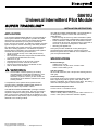
S8610U
Universal Intermittent Pilot Module
SUPER TRADELINE ®
INSTALLATION INSTRUCTIONS
APPLICATION
The SUPER TRADELINE® S8610U Universal Replacement Ignition Module is designed to provide easy field
replacement of a wide range of intermittent pilot ignition
modules manufactured by Honeywell, Robertshaw,
Penn-Johnson and others. The S8610U module provides
ignition sequence, flame monitoring, and safety shutoff
for intermittent pilot central furnaces, residential boilers,
and other heating appliances. The S8610U replaces
existing flame rectification type intermittent pilot ignition
modules with the following characteristics:
• Single rod (local sense) or two rod (remote sense)
flame sensing.
• Non-100 percent shutoff, 100 percent shutoff/lockout,
or 100 percent shutoff/continuous retry.
• Natural or LP gas.
• Shutoff/lockout times of 30 seconds or longer.
• Prepurge times of four seconds or shorter.
• Pilot burners with flow rates of 1500 Btuh or less.
• With or without vent dampers.
WARNING
Check Table 1 before replacing an existing
intermittent pilot module with the S8610U. If the
existing module is not listed, do not use the
S8610U to replace it unless you are certain the
specifications of the S8610U match those of the
existing module.
A complete list of the specific Honeywell and other
modules that the SUPER TRADELINE® S8610U is
designed to replace is provided in Table 1.
The S8610U SUPER TRADELINE® package contains
complete, easy-to-use instructions, plus the accessories
required to adapt the existing spark cable (Rajah, stud,
nail, or other) to the spark terminal on the S8610U. It also
provides labels to help assure proper marking of the wires
attached to the existing module.
®U.S. Registered Trademark
Copyright © 1996 Honeywell Inc. • All Rights Reserved
The S8610U SUPER TRADELINE® Universal Module is
not designed to replace controls with the following
characteristics:
• Flame sensing other than by flame rectification (White
Rodgers Cycle-Pilot®, or Robertshaw thermal sensing).
• Flame rectification modules with shutoff/lockout times
of less than 30 seconds, prepurge times of more than 4
seconds, or pilot burners larger than 1500 Btuh.
• Standing pilot appliances.
Honeywell provides additional control packages to
accomplish these replacements. See the Honeywell
Electronic Ignition Service Manual, form 70-6604, or call
your Honeywell wholesaler.
SPECIFICATIONS
Electrical Ratings:
Voltage: 24V, 60 Hz.
Current Draw: 1A pilot valve, 2A main valve.
Valve Contact Rating: 0.2A.
Trial For Ignition:
90 seconds maximum, then 100 percent shutoff (pilot and
main gas).
Continuous Retry:
Five-minute minimum (six-minute nominal) delay if pilot
fails to light during trial for ignition. After delay, trial for
ignition is repeated. This sequence (trial, delay, trial, delay)
continues until pilot lights or call for heat ends.
Flame Failure Response Time:
0.8 sec max at 1.0 uA flame current.
Ambient Operating Temperature:
-40°F to 165°F (-40°C to 74°C). (If main valve current is 1A
or less, 175°F (79°C) maximum ambient applies.)
X-XX UL
69-0729-3
S8610U UNIVERSAL INTERMITTENT PILOT MODULE
Table 1. S8610U Replaces these Ignition Modules.
Camstat
IPI-24-00
Fenwal
05-203025-005
05-203026-005
Honeywell
S86A1001
S86A1019
S86A1027
S86A1035
S86B1009
S86B1017
S86B1025
S86C1007
S86C1015
S86C1031
S86C1049
S86C1056
S86D1005
S86D1021
S86E1002
S86E1010
S86E1028
S86E1036
S86E1044
S86E1051
S86E1069
S86E1077
S86E1101
S86E1119
S86E1127
S86F1000
S86F1018
S86F1026
S86F1042
S86F1059
S86F1067
S86F1075
S86F1083
S86F1091
S86G1008
S86G1016
S86G1032
S86G1057
S86G1073
S86H1006
S86H1022
S86H1048
69-0729—3
S86H1089
S86H1097
S86H1105
S86H1121
S86H1147
S90A1005
S90B1003
S90B1011
S8600A1001
S8600B1009
S8600C1015
S8600F1000
S8600F1034
S8600F1042
S8600H1006
S8600H1022
S8600H1048
S8600H1055
S8600H1089
S8600H1105
S8600M1005
S8600M1013
S8610A1009
S8610B1007
S8610B1015
S8610C1005
S8610F1008
S8610F1016
S8610F1024
S8610F1032
S8610H1012
S8610H1038
S8610H1046
S8610H1053
S8610H1079
S8610M1003
S8610M1029
S8620H1028
HSC
1003-3
1003-300
PennJohnson
CSA35A-617R
CSA35A-618R
CSA42A-600R
CSA42A-601R
G60PAG-5
G60PAG-6
G60PAJ-1
G60PAK-1
G60PAK-2
G60PFH-1
G60PFH-2
G60PFL-1
G60PFQ-1
G60PVL-1
G60QAG-2
G60QAG-3
G60QAK-1
G60QBG-1
G60QBG-2
G60QBG-3
G60QBG-4
G60QBG-5
G60QBG-6
G60QBG-7
G60QBG-8
G60QBG-9
G60QBH-1
G60QBK-1
G60QBK-3
G60QBL-1
G60QBL-2
G60QCG-1
G60QCJ-1
G60QCL-1
G60QDG-1
G60QFL-1
G60QHL-1
G60QJL-1
G60QLG-1
G60QPL-1
G60QRH-1
G60QRL-1
G60QRL-2
G60QRL-3
G60QSL-1
G60QTH-1
G60QTL-1
G60RAG-1
G60RAK-1
G60RBG-1
G60RBG-2
G60RBG-3
G60RBK-1
G60RBK-2
CSA42A-603R
CSA42A-604R
CSA43A-600R
CSA44A-600R
CSA45A-601R
CSA45A-602R
CSA46A-600R
CSA48A-600R
CSA49A-600R
CSA49A-605R
CSA51A-601R
CSA52A-600R
G60AAA-1
G60AAG-1
G60AAG-3
G60AAG-4
G60AAG-5
G60AAG-6
G60CAA-1
G60CAA-3
G60CAG-1
G60CAG-2
G60CAG-3
G60CAG-4
G60CAG-5
G60CAG-6
G60CAG-7
G60CAG-8
G60CAG-9
G60CBA-1
G60CBA-3
G60CBG-1
G60CBG-10
G60CBG-11
G60CBG-14
G60CBG-16
G60CBG-17
G60CBG-3
G60CBG-4
G60CBG-9
G60CCA-1
G60CCG-1
G60CPG-1
G60DBG-1
G60DCG-1
G60DCG-2
G60PAG-1
G60PAG-2
G60PAG-3
G60PAG-4
2
G60RCG-2
G60RCJ-1
G60RDG-1
G60RDK-1
G60RGL-1
G60RHL-1
G60RHP-1
G60RPL-1
G60RSL-1
G60ZAG-1
G65BBG-1
G65BBG-2
G65BBG-3
G65BBG-4
G65BBG-5
G65BBG-6
G65BBG-7
G65BBG-8
G65BBM-1
G65BBM-2
G65BBM-3
G65BBM-4
G65BCG-1
G65BCM-1
G65BFG-1
G65BFM
G65BKG-1
G65BKG-2
G65BKG-3
G65BKM-1
G65BKM-2
G65BKM-3
G65DBG
G65DBM-1
G65DBM-3
G65DCM-1
G65DFG
G65DFM-1
G65DKG
G65DKM
G65FBG
G65FFG
G65FKG
G66AG-1
G66BG-1
G66MG-1
G66NG-1
G67AG-3
G67AG-4
G67AG-7
G67AG-8
G67BG-2
G67BG-3
G67BG-4
G67BG-5
G67MG-1
G67MG-4
G67NG-2
G600AX-1
G600AY-1
G600MX-1
G600NX-1
G600RX-1
G670AW-1
G770MGA-1
G770MGA-2
G770MGC-1
G770MGC-2
G770MGC-3
G770MHA-1
G770NGA-1
G770NGC-4
G770NGC-5
G770NGC-6
G770NGC-7
G770RGA-1
G770RHA-1
G770MHA-2
G770MHC-1
G770NHA-1
G770NHC-1
G770RHA-2
Robertshaw
780-715
780-735
780-737
SP715
SP715A
SP735
SP735D
SP735L
USI 715U
S8610U UNIVERSAL INTERMITTENT PILOT MODULE
Dust or Grease Accumulation
PLANNING THE INSTALLATION
Heavy accumulations of dust or grease can cause
controls to malfunction. Where dust or grease can be a
problem, provide covers for the module and the gas
control to limit contamination. A NEMA 4 enclosure is
recommended for the ignition module; see the Electronic
Ignition Service Manual, form 70-6604.
WARNING
FIRE OR EXPLOSION HAZARD
CAN CAUSE PROPERTY DAMAGE,
SEVERE INJURY, OR DEATH.
Follow these warnings exactly:
1. Plan the installation as outlined below.
2. Plan for frequent maintenance as described in
the Maintenance section.
Heat
Excessively high temperatures can damage controls.
Make sure the maximum ambient temperature at the
control does not exceed the rating of the control. If the
appliance operates at very high temperatures, use
insulation, shielding, and air circulation, as necessary, to
protect the controls. Proper insulation or shielding should
be provided by the appliance manufacturer; verify proper
air circulation is maintained when the appliance is
installed.
When intermittent pilot systems are used on central
heating equipment in barns, greenhouses, and commercial properties and on heating appliances such as
commercial cookers, agricultural equipment, industrial
heating equipment and pool heaters, heavy demands are
made on the controls. Special steps can be required to
prevent nuisance shutdowns and control failure due to
frequent cycling, severe environmental conditions related
to moisture, corrosive chemicals, dust or excessive heat.
These applications require Honeywell Home and
Building Control Engineering review; contact your
Honeywell Sales Representative for assistance.
INSTALLATION
When Installing this Ignition System…
1. Read these instructions carefully. Failure to follow
them could damage the components or cause a
hazardous condition.
2. Check the ratings given in the instructions and on
the components to make sure they are suitable for
your application.
3. Installer must be a trained, experienced service
technician.
4. After installation is complete, check out component
operation as provided in these instructions.
Review the following conditions that can apply to your
specific installation and take the precautionary steps
suggested.
Frequent Cycling
These controls are designed for use on appliances that
typically cycle three to four times an hour only during the
heating season. In year-round applications with greater
cycling rates, the control can wear out more quickly;
perform a monthly checkout.
WARNING
FIRE OR EXPLOSION HAZARD
CAN CAUSE PROPERTY DAMAGE,
SEVERE INJURY, OR DEATH.
1. If the ignition module gets wet, it can
malfunction, leading to the accumulation of
explosive gas.
• Never install where water can flood, drip or
condense on the module.
• Never use a module that has been wet.
Replace it.
2. Liquefied petroleum (LP) gas is heavier than
air and will not vent upward naturally.
• Do not light the pilot or operate electric
switches, lights or appliances until you are
sure the appliance area is free of gas.
3. Do not attempt to disassemble or clean the
module. Improper reassembly and cleaning
can cause unreliable operation.
Water or Steam Cleaning
If a module or gas control gets wet, replace it. If the
appliance is likely to be cleaned with water or steam,
protect (cover) the controls and wiring from water or
steam flow. Mount the controls high enough above the
bottom of the cabinet so they do not get wet during
normal cleaning procedures. Use a NEMA 4 enclosure
for the ignition module; see the Electronic Ignition
Service Manual, form 70-6604.
High Humidity or Dripping Water
Dripping water can cause the module to fail. Never install
an appliance where water can drip on the controls.
In addition, high ambient humidity can cause the gas
control to corrode and fail.
If the appliance is in a humid atmosphere, make sure air
circulation around the controls is adequate to prevent
condensation. Also, regularly check out the system. A
NEMA 4 enclosure is recommended for the ignition
module; see the Electronic Ignition Service Manual,
form 70-6604.
CAUTION
1.
2.
Corrosive Chemicals
Corrosive chemicals can attack the module and gas
control, eventually causing a failure. If chemicals are
used for routine cleaning, make sure they do not reach
the controls. Where chemicals are suspended in air, as
in some industrial or agricultural applications, use a
NEMA 4 enclosure for the ignition module; see the
Electronic Ignition Service Manual, form 70-6604.
3.
4.
3
Disconnect power supply before beginning
wiring to prevent electrical shock or equipment damage.
If a new gas control is to be installed, turn off
the gas supply before starting installation.
Conduct a Gas Leak Test according to the
gas control manufacturer instructions after
the gas control is installed.
If the module must be mounted near
moisture or water, provide a suitable
waterproof enclosure.
Using the wire labels provided, label all wires
before they are disconnected. Wiring errors
can cause improper appliance operation and
dangerous conditions such as bypassing
safety features.
69-0729—3
S8610U UNIVERSAL INTERMITTENT PILOT MODULE
A Connect the wires to the S8610U Ignition Module as
shown in Tables 3 through 6. Make sure that
adequate system ground is provided as indicated in
the wiring tables.
B Verify the thermostat anticipator setting as explained
in the Important.
Perform Preinstallation Safety Inspection
The preinstallation checks described in ANSI Standard
Z21.71 in Exhibit A must be done before the replacement
module is installed. If a condition that could result in unsafe
operation is detected, the appliance should be shut off and
the owner advised of the unsafe condition. Correct any
potentially unsafe condition before proceeding with the
installation.
NOTE: The wiring diagrams in Fig. 2 through 4 show
typical hookups with the S8610U Ignition Module
and should be used for reference only.
Remove Old Module
Disconnect power supply before doing any work on the
unit. Disconnect and tag the wires from the old module
using the wire labels provided. Remove the old module
from its mounting location.
MOUNT IN ONE OF THESE POSITIONS
Mount New Ignition Module
We recommend mounting the S8610U Module in the
same location as the old module, if possible. Otherwise,
select a location close enough to the burner to allow a
short (3 ft. (0.9 m) maximum), direct cable route to the
igniter. Ambient temperature at the module must be within
the range listed in the Application section.
TERMINALS FACING DOWN
Mount the module with the terminals down to protect
them from dripping water and dust. The module can also
be mounted with the terminals on either side. Do not
mount with the terminals pointing up. Refer to Fig. 1 for
mounting recommendations. When it is necessary to drill
new mounting holes, use the S8610U as a template to
mark mounting hole pattern. Drill new holes, as required.
Fasten securely with four No. 6-32 machine or No. 8
sheetmetal screws.
Wire the Module
TERMINALS FACING LEFT
CAUTION
1.
2.
Check the wiring diagram furnished by the
appliance manufacturer, if available, and
compare with Tables 3 through 6. Carefully
follow any special instructions affecting the
general wiring procedures outlined below.
Disconnect the power supply before making
wiring connections to prevent electrical shock
or equipment damage.
DO NOT MOUNT
WITH TERMINALS FACING UP
IMPORTANT
1. A common ground is required on:
a. The pilot burner mounting bracket, and
b. The GND (BURNER) terminal on the ignition
module. Failure to use the GND (BURNER)
terminal can result in intermittent loss of spark
and/or loss of flame current sensitivity.
2. Make sure the transformer has adequate VA.
The ignition module requires at least 0.2A at 24
Vac. Add the current draws of all other devices in
the control circuit, including the pilot and main
valves in the gas control, and multiply by 24 to
determine the total VA requirement of these
components. Add this total to 4.8 VA (for the
ignition module). The result is the minimum
transformer VA rating. Use a Class II transformer
when replacement is required.
3. When a vent damper is connected to the S8610U
vent damper connector, be sure the system
transformer delivers at least 30 VA. The S8610U
has an internal fuse that is intended to prevent
appliance lightoff if the vent damper is not in
place or wired properly. Using a small transformer can interfere with the proper operation of
the fuse and bypass the intended safety feature.
69-0729—3
TERMINALS FACING RIGHT
M2647
Fig. 1. Module mounting recommendations.
Modify Ignition Cable, If Necessary
Use existing ignition cable if it is in good condition. If the
existing ignition cable does not have a 1/4 in. quickconnect on the module end, either use the Rajah adapter
or strip the wire and replace with the 1/4 in. insulated
quick-connect supplied. If the cable must be replaced,
order a Honeywell ignition cable, see Table 2. It might be
necessary to replace the connector at the pilot burner end
to match the pilot burner spark termination.
NOTE: When using an S8610U to replace an S86, use
the enclosed adapter to convert the S86 Ignition
Cable to an S8610U Ignition Cable. Then,
install the adapter and cable to the S8610U
Ignition Module.
4
S8610U UNIVERSAL INTERMITTENT PILOT MODULE
Table 2. Honeywell Preassembled Ignition
Cables (UL Style 3257).
Cable Part
Number
Length
394800-30
30 in.
394801-30
30 in.
Module
End
NOTE: The cable must not run in continuous contact
with a metal surface or spark voltage is greatly
reduced. Use ceramic or plastic standoff
insulators, as required.
Igniter End
1/4 in.
quick
connect,
insulated
Rajah connector
receptacle, 90
degree rubber
boot
1/4 in.
quick
connect,
insulated
Rajah connector
receptacle,
straight rubber
boot
Arc Table
Arc Length
No arc or arc
less than 1/8 in.
(3 mm)
Arc 1/8 in. (3 mm)
or longer.
Action
Check external fuse, if provided.
Verify power at module input
terminal. Replace module if fuse
and power are okay.
Voltage output is okay.
Table 3. Conversion from Honeywell S86, S90, S8600 and S8610 to S8610U1003.
Replacement
Control
Old Control
S8610U1003
S86A,C
S86B,D
S86E,F,G,H
S8600A,B,C
S8610A,B,C
S90A,B
Main valve
operator
MV
MV
MV
MV
MV
MV
Main valve
and pilot
common
MV/PV
MV/PV
MV/PV
MV/PV
MV/PV
MV/PV
Pilot valve
operator
PV
PV
PV
PV
PV
PV
Burner
ground
connection
GND
(BURNER)
GND
GND
GND
(BURNER)
GND
(BURNER)
GND
(BURNER)
Transformer
secondary
(unswitched
leg)
24V GND
25V (1)
25V (GND)
25V (1)e
24V GND
24V GND
Transformer
secondary
(switched
leg)
24V*
25V (2)
25V
25V (2)e*
24V*
24V*
Terminal
Function
S8600F,H,M
S8610F,H,M
25V (2) or 24V used only in systems where
plug-in cable connects damper to module.
TH-W
Flame
sensor
SENSEf
Igniter/
sensor
SPARK
TH-R a
TH-R a
TH-R a
TH-Wb
TH-W
TH-Wb
d
d
IGN COILc IGN COILc
TH-W (This
terminal
not included on
S90.)
TH-W
d
SENSEf
d
IGN COILc
SPARK
SPARK
Procedural Notes
* Important: If the old module had a vent
damper plug but a vent damper was not
installed, or if it did not have a vent
damper plug: leave the vent damper plug
in position on the S8610 and connect the
25V (2) or 24V wire from the old module
to the TH-W terminal on the S8610U. Do
not use the 24V terminal on the
S8610U.
If the old module had a vent damper with
a plug connection to a Molex connector,
wire the terminals as indicated in the
table.
a If 25V (2) and TH-R have wires connected, disconnect and splice together with solderless connector.
b If TH-R and TH-W are jumpered together, connect 25V (2) lead from S86 to TH-W on S8610U1003.
c Use Rajah to quick connector adapter (supplied) or cut Rajah connector off ignition cable at module end; attach insulated quick
connect for connection to S8610.
d Leave black jumper connected.
e Terminals may be marked 25V on some models and 24V on later models. These are functionally equivalent.
f On dual igniter and sensor models, remove jumper quick connect from S8610U1003 Sense terminal, cut jumper wire at circuit board,
and discard.
5
69-0729—3
S8610U UNIVERSAL INTERMITTENT PILOT MODULE
Table 4. Conversion from Robertshaw SP715 and SP735C to S8610U1003 (Includes 780-XXX and USI715U).
Replacement
Control
Terminal Function
Honeywell
S8610U1003
Main valve operator
Old Control SP715 and SP735
(includes 780-XXX and USI 715U) c,d
7000D Valve
7100D Valve
7100K Valve
MV
MV
(to: Valve TH)
MV
(to: Valve M)
MV
(to: Valve TR)
Main valve and pilot
common
MV/PV
MV/PV
(to: Valve TR)
MV/PV
(to: Valve C)
Pilot valve operator
PV
PV
(to: Valve
PILOT)*
PV
(to: Valve P)
PV
(to: Valve PICK &
HOLD)
GND
(BURNER)
GND
GND
GND
—
24V GND
TR
TR
TR
—
24V
No connection
No
connection
No connection
—
E3a
E3a
E3a
When supplied, E3
provides connection to
Lockout Timer.
TH-W
TH
TH
TH
If LO-15 is part of the
installation, use the
wire disconnected from
E1 tagged Thermostat.
Flame sensor
SENSE b
SENSE e
SENSE e
SENSE e
—
Pilot igniter
SPARK
IGN
IGN
IGN
—
Burner
connection
ground
Transformer
secondary
(unswitched leg)
Transfomer
secondary
(switched leg)
Procedural Notes
—
PV
—
(to: Valve C and TH)
*This is the terminal not
jumpered to TR.
1. Use existing wiring harness to make connections to S8610 per table. IMPORTANT: If installation includes LO-15
Lockout Timer, discard wires to E3 and TH. Disconnect and retain wire to LO-15 terminal E1. Tag wire,Thermostat.
Discard LO-15.
2. On 7000D series valve, retain (or install) white jumper between valve TR and pilot solenoid.
a If LO-15 Lockout timer is not installed, E3 connector provided on SP715 is not used.
b Important: If the USI 715U with combination igniter sensor is not used, remove black jumper quick connect from
Sense terminal of S8610U1003. Cut jumper wire at circuit board and discard.
c For replacement of Robertshaw Flame Switch systems (SP710, 720, 730, 750, 780-700, 780-701, 780-710, 780-711,
780-712 and 780-713), see Honeywell Ignition Control Handbook.
d 780-715 and USI 715U are equivalent to SP715; 780-735 and 780-737 are equivalent to SP735. For other 780-XXX
models, see notec.
e OPT. SENSOR on USI 715U. No external connection if combination igniter sensor is used.
69-0729—3
6
S8610U UNIVERSAL INTERMITTENT PILOT MODULE
Table 5. Conversion from Penn-Johnson CSA—(All), G60, G65, G66, G67, G600, G670 Or G770 to S8610U1003.
Replacement
Control
Old Control
CSA45A-600R d, G60, G65, G66, G67,
G600 OR G670 Installation with
Lockout Modules as follows:*
Honeywell
S861U1003
None (Y79)
Y79A
module d
Y79B
module c
G770
MV
3
3
Y79B MV
MV (3)
MV/PV
GR
GR
GR
GROUND(5)
PV
1
1
Y79B PV
PV (1)
Burner ground
connection
GND
(BURNER)
GR
GR
GR
GROUND
Transformer
secondary
(unswitched leg)
24V GND
GR
GR
GR
GROUND
TH-W*
2a
Y79 THSb
2
TH-S (2)
24V*
No
connection*
4e
No
connection*
4e
No
connection*
SENSE (4)e
IGN COIL
IGN COIL
IGN COIL
Terminal
Function
Main valve
operator
Main valve and
pilot common
Pilot valve
operator
Transformer
secondary
(switched leg)
Flame sensor
SENSE*
No
connection*
4e
Pilot igniter
SPARK
IGN COIL
Procedural Notes
It might be
necessary to cut off
Rajah connector
and/or attach
insulated quick
connect.
a Discard wire between transformer and terminal 5 (G60) or 6 (G600); otherwise, use existing harness for wiring.
b Discard wires between Y79A and module as follows: Red to 3, Black to 2, White to GR. Discard wire between
transformer and 6.
c Discard wires between Y79B and module as follows: White to 3, Black to 1, Brown to GR. Discard wire between
transformer and 6.
d CSA code numbers (for example, CSA45A-600R) are equivalent to G600 and use the same wiring information tables.
e Important: Remove black jumper quick connect from Sense terminal of S8610U1003; cut jumper wire at circuit board
and discard.
*IF INSTALLATION DOES NOT INCLUDE VENT DAMPER WITH PLUG CONNECTION TO MODULE:
1. Leave vent damper plug on S8610U Module in position.
2. Use TH-W terminal.
*IF INSTALLATION INCLUDES VENT DAMPER WITH PLUG CONNECTION TO MODULE:
1. Replace S8610U Module vent damper plug with damper Molex connector.
2. Wire thermostat W wire to TH-W.
3. Run wire from switched leg of transformer secondary to both thermostat R and S8610 Module 24V terminals.
7
69-0729—3
S8610U UNIVERSAL INTERMITTENT PILOT MODULE
Table 6. Conversion from Camstat, Fenwal or HSC to S8610U1003.
Replacement
Control
Terminal
Function
Old Control
Honeywell
S8610U1003
CAMSTAT
IPI-24-00 a
FENWAL
05-20X b
HSC 1003-3
and 1003-300 a
MV
MV
MAIN VALVE
MV
MV/PV
GND
GROUND
GND/COM
PV
PV
PILOT VALVE
PV
—
Burner ground
connection
GND
(BURNER)
GND
—
—
To assure good ground, run
separate wire from pilot
burner to S8610 GND
(BURNER).
Transformer
secondary
(unswitched leg)
24V GND
T2
GROUND
GND/COM
—
No connection
—
Main valve
operator
Main valve and
pilot common
Pilot valve
operator
24V
No connection No connection
Procedural Notes
—
Fenwal only: run separate
lead to S8610 valve
common terminal.
Transformer
secondary
(switched leg)
TH-W
T1
POWER
24 VAC
—
Flame sensor
SENSE
Sc
—
SENSORc
—
Pilot igniter
SPARK
IGN
H.V.
IGN COIL
Strip module end of ignition
cable as necessary and
attach insulated quick
connect for connection to
S8610.
a Use existing wiring harness to make connections to S8610.
b Tag all wires at module connector with terminal designations. Cut wires at connector, attach quick connects and
connect to S8610; per table.
c Important: Remove black jumper quick connect from Sense terminal of S8610U1003; cut jumper wire at circuit board
and discard.
69-0729—3
8
S8610U UNIVERSAL INTERMITTENT PILOT MODULE
S8610U
5
GND
(BURNER)
MV MV/PV PV
24V
GND
24V TH-W
VENT
DAMPER
PLUG
6
7
PILOT
SPARK
SENSE
3
WIRING
HARNESS
MAIN
VALVE
COM
1ST
2ND
OPERATOR OPERATOR
THERMOSTAT
D892 VENT
DAMPER
2
DUAL VALVE COMBINATION
GAS CONTROL
LIMIT
CONTROLLER 1
SENSOR
L1
(HOT)
4
L2
8
GROUND
IGNITER
PILOT GAS
SUPPLY
1
POWER SUPPLY. PROVIDE DISCONNECT MEANS AND OVERLOAD PROTECTION AS REQUIRED.
2
ALTERNATE LIMIT CONTROLLER LOCATION.
3
MAXIMUM CABLE LENGTH 3 ft (0.9m).
4
CONTROLS IN 24V CIRCUIT MUST NOT BE GROUND LEG TO TRANSFORMER.
5
REMOVE PLUG ONLY IF USING VENT DAMPER. FUSE BLOWS ON STARTUP WHEN PLUG IS
REMOVED AND VENT DAMPER WIRING HARNESS IS INSTALLED; THEN MODULE OPERATES
ONLY WHEN VENT DAMPER IS CONNECTED.
6
REMOVE JUMPER AND CONNECT SENSE TERMINAL ON TWO ROD APPLICATION ONLY.
7
IF THE VENT DAMPER IS CONNECTED, WIRE 24V TERMINAL, AS SHOWN. CONNECT VENT
DAMPER CABLE IN PLACE OF PLUG SHIPPED WITH THE S8610U. IF NO VENT DAMPER IS
CONNECTED, DO NOT WIRE 24V TERMINAL.
8
30 VA MINIMUM WHEN VENT DAMPER IS CONNECTED TO DAMPER PLUG.
M2641D
Fig. 2. S8610U in heating system with atmospheric burner.
S8610U
5
MV MV/PV PV
PILOT
GND
(BURNER)
24V
GND
VENT
DAMPER
PLUG
1ST
2ND
OPERATOR OPERATOR
SENSE
6
AIR
PROVING
SWITCH
MAIN
VALVE
COM
24V TH-W
SPARK
3
THERMOSTAT
2
DUAL VALVE COMBINATION
GAS CONTROL
COMBUSTION
AIR BLOWER
RELAY
4
SENSOR
LIMIT
CONTROLLER
1
IGNITER
PILOT
BURNER
GROUND
PILOT GAS
SUPPLY
L1 L2 COMBUSTION
(HOT) AIR BLOWER
MOTOR
1 L2 L1
(HOT)
CONTROLLER
1
POWER SUPPLY. PROVIDE DISCONNECT MEANS AND OVERLOAD PROTECTION AS REQUIRED.
2
ALTERNATE LIMIT CONTROLLER LOCATION.
3
MAXIMUM CABLE LENGTH 3 ft (0.9m).
4
CONTROLS IN 24V CIRCUIT MUST NOT BE GROUND LEG TO TRANSFORMER.
5
LEAVE VENT DAMPER PLUG CONNECTED.
6
REMOVE JUMPER AND CONNECT SENSE TERMINAL ON TWO ROD APPLICATION ONLY.
M2642B
Fig. 3. S8610U in heating system with power-assisted combustion.
9
69-0729—3
S8610U UNIVERSAL INTERMITTENT PILOT MODULE
START
1
STAGE 1
2
TRIAL FOR
IGNITION
THERMOSTAT (CONTROLLER)
CALL FOR HEAT
SPARK GENERATOR POWERED
First valve (pilot) operator opens
3
PILOT BURNER OPERATION
Pilot burner lights.
Module senses
flame current.
STAGE 2
4
MAIN BURNER
OPERATION
5
6
END
After 90 seconds maximum, system shuts off; trial for
ignition restarts after minimum of 5 minutes (6 minutes
nominal). Ignition, shutoff, wait sequence repeats until
pilot lights or call for heat ends.
OR
FLAME CURRENT SENSED
• Spark generator off.
• Second valve operator
(main) opens.
POWER INTERRUPTION
System shuts off, restarts when power
is restored.
MAIN BURNER OPERATION
Module monitors pilot
flame current.
PILOT FLAME FAILURE
Main valve closes.
Module starts trial for ignition.
THERMOSTAT (CONTROLLER)
SATISFIED
Valves close, pilot and main
burners are off.
M2640A
Fig. 4. S8610U in typical ST9120 application.
STARTUP AND CHECKOUT
d.
Check out the gas control system:
• At initial installation of the appliance.
• As part of regular maintenance procedures.
• At maintenance intervals determined by the application.
• As the first step in troubleshooting.
• Any time work is done on the system.
Gas Leak Test:
Paint the gas control gasket edges and all pipe connections downstream of the gas control, including the pilot
tubing connections, with a rich soap and water solution.
Bubbles indicate gas leaks. Tighten the joints and screws
or replace component to stop gas leak. Recheck with soap
and water solution.
Maintenance frequency must be determined individually
for each application; see Maintenance section.
WARNING
Step 2: Verify control system ground.
FIRE OR EXPLOSION HAZARD
CAN CAUSE PROPERTY DAMAGE,
SEVERE INJURY, OR DEATH.
1. If you smell gas or suspect a gas leak, turn off
the gas at the manual service valve and
evacuate the building. Do not try to light any
appliance; do not touch any electrical switch
or telephone in the building until you are sure
no spilled gas remains.
2. Gas leak test must be done as described in
Steps 1 and 6 below during initial installation
and anytime work is done involving the gas
piping.
The igniter, flame sensor, and ignition module must share
a common ground with the main burner. Use thermoplastic
insulated wire with a minimum rating of 105°C (221°F) for
the ground wire; asbestos insulation is not acceptable. If
the temperature at the wire could exceed 105°C (221°F),
use a shield to protect the wire from radiant heat generated by the burner. Connect the ground wire as follows:
a. Fit one end of the ground wire with a female 1/4 in.
quick-connect terminal and connect it to the male
quick-connect GND (BURNER) terminal on the
ignition module.
b. Strip the other end of the wire and fasten it under the
igniter bracket mounting screw. If necessary, use a
shield to protect the ground wire from radiant heat.
c. The burner serves as the common grounding area. If
there is not good metal-to-metal contact between the
burner and ground, run a lead from the burner to
ground.
Step 1: Perform visual inspection.
a.
b.
c.
With power off, make sure all wiring connections are
clean and tight.
Turn on the power to the appliance.
Open the manual shutoff valves in the gas line to the
appliance.
69-0729—3
Test for gas leak before gas control if piping has been
disturbed.
NOTE: Earth ground is not required.
10
S8610U UNIVERSAL INTERMITTENT PILOT MODULE
Step 3: Review normal operating sequence
and module specifications.
a.
MAINTENANCE
WARNING
See Operation and Application sections.
FIRE OR EXPLOSION HAZARD
CAN CAUSE PROPERTY DAMAGE,
SEVERE INJURY, OR DEATH.
Do not attempt to take the module apart or to clean
it. Improper assembly and cleaning can cause
unreliable operation.
Step 4: Reset the module.
a. Turn the thermostat to its lowest setting.
b. Wait one minute.
As you do Steps 4 and 5, watch for points where operation
deviates from normal. Refer to Troubleshooting Guide, Fig.
7, to correct problem.
Regular preventive maintenance is important in applications that place a heavy load on system controls, such as
in the commercial cooking and agricultural and industrial
industries because:
• In many applications, particularly commercial cooking,
the equipment operates 100,000 to 200,000 cycles
per year. Such heavy cycling can wear out the gas
control in one to two years.
• Exposure to water, dirt, chemicals and heat can
damage the gas control and shut down the control
system. A NEMA 4 enclosure can reduce exposure to
environmental contaminants. See electronic Ignition
Service Manual, form 70-6604.
Step 5: Check safety shutoff operation.
a.
b.
c.
d.
e.
f.
Turn off the gas supply.
Set the thermostat or controller above the room
temperature to call for heat.
Watch for spark at pilot burner.
Time spark from start to shutoff. Spark should shut
off after 90 seconds maximum. Ignition sequence
repeats after five minutes minimum.
Open manual gas control knob and make sure no
gas is flowing to pilot or main burner.
Set the thermostat below the room temperature and
wait one minute before continuing.
The maintenance program should include regular system
checkout as outlined in the Startup and Checkout
section, and the control system as described in the
appliance manufacturer literature.
Step 6: Check normal operation.
a.
b.
c.
d.
e.
Set the thermostat or controller above the room
temperature to call for heat.
Make sure the pilot lights smoothly when the gas
reaches the pilot burner.
Make sure the main burner lights smoothly without
flashback.
Make sure the burner operates smoothly without
floating, lifting, or flame rollout to the furnace
vestibule or heat buildup in the vestibule.
If the gas line has been disturbed, complete the gas
leak test.
Maintenance frequency must be determined individually
for each application. Some considerations are:
• Cycling frequency. Appliances that can cycle 20,000
times annually should be checked monthly.
• Intermittent use. Appliances that are used seasonally
should be checked before shutdown and again before
the next use.
• Consequence of unexpected shutdown. Where the
cost of an unexpected shutdown would be high, the
system should be checked more often.
• Dusty, wet, or corrosive environment. Because these
environments can cause the gas control to deteriorate
more rapidly, the system should be checked more
often.
Gas Leak Test:
Paint the gas control gasket edges and all pipe connections downstream of the gas control, including pilot
tubing connections, with a rich soap and water solution.
Bubbles indicate gas leaks. Tighten the joints and
screws or replace component to stop gas leak. Recheck
with soap and water solution.
f.
Any control should be replaced if it does not perform
properly on checkout or troubleshooting. In addition,
replace any module if it is wet or looks like it has ever
been wet. Protective enclosures, as described in
Planning the Installation section, are recommended
regardless of checkout frequency.
Turn the thermostat or controller below the room
temperature. Make sure the main burner and pilot
flames go out.
11
69-0729—3
S8610U UNIVERSAL INTERMITTENT PILOT MODULE
START
TURN OFF GAS SUPPLY.
TURN THERMOSTAT
(CONTROLLER) TO CALL
FOR HEAT.
NOTE: Before troubleshooting, familiarize yourself with the startup and checkout procedure.
POWER TO MODULE.
(24V NOMINAL)
CHECK AT TH-W TERMINAL,
AND ALSO AT 24V TERMINAL
IF A VENT DAMPER IS
CONNECTED TO THE
DAMPER CONNECTOR.
Check line voltage power, low voltage transformer, limit controller, thermostat (controller) and wiring. Also,
check air proving switch on combustion air blower system (if used) and verify that vent damper (if used) is open
and end switch is made.
NO
YES
SPARK ACROSS
IGNITER/SENSOR GAP?
NO
Pull ignition lead and
check spark at module.
NO
• On models with vent damper plug, make sure vent damper
was not installed, then removed. Replace vent damper,
if necessary.
• On other models, replace module.
Spark okay?
YES
YES
• Check ignition cable, ground wiring, ceramic insulator and gap, and correct.
• Check boot of the ignition cable for signs of melting or buckling. Replace cable and take protective action
to shield cable and boot from excessive temperatures.
TURN ON GAS SUPPLY.
NO
PILOT BURNER LIGHTS?
YES
SPARK STOPS WHEN
PILOT IS LIT?
NO
YES
MAIN BURNER LIGHTS?
NO
• Check that all manual gas valves are open, supply tubing and pressures are good, and pilot burner orifice
is not blocked.
• Check electrical connections between module and pilot operator on gas control.
• Check for 24 Vac across PV-MV/PV terminals on module. If voltage is okay, replace gas control; if not,
replace module
•
•
•
•
•
•
•
Check continuity of ignition cable and ground wire.
Clean flame rod.
Check electrical connections between flame rod and module.
Check for cracked ceramic flame rod insulator.
Check that pilot flame covers flame rod and is steady and blue.
Adjust pilot flame.
If problem persists, replace module.
• Check for 24 Vac across MV-MV/PV terminals. If no voltage, replace module.
• Check electrical connections between module and gas control. If okay, replace gas control or gas
control operator.
YES
SYSTEM RUNS UNTIL
CALL FOR HEAT ENDS?
NO
YES
CALL FOR HEAT ENDS.
SYSTEM SHUTS OFF?
NO
• Check continuity of ignition cable and ground wire.
NOTE: If ground is poor or erratic, shutdowns can occur occasionally even though operation is normal
at the time of checkout.
• Check temperature at igniter-sensor insulator. High temperatures can cause a short.
• Check that pilot flame covers flame rod and is steady and blue.
• If checks are okay, replace module.
• Check for proper thermostat (controller) operation.
• Remove MV lead at module; if valve closes, recheck temperature controller and wiring; if not, replace
gas control.
YES
TROUBLESHOOTING
ENDS.
Repeat procedure until troublefree operation is obtained.
M2643B
Fig. 5. S8610U normal operating sequence.
69-0729—3
12
S8610U UNIVERSAL INTERMITTENT PILOT MODULE
Step 2: Check ignition system grounding. Nuisance shutdowns are often caused by a poor or
erratic ground.
OPERATION
Module operation can be conveniently divided into two
phases for the S8610:
• Trial for ignition.
• Main burner operation.
a.
Fig. 5 summarizes the normal module operating sequence.
TROUBLESHOOTING
IMPORTANT
1. The following service procedures are provided as
a general guide. Follow appliance manufacturer
service instructions if available.
2. Meter readings between gas control and ignition
module must be taken within the trial for ignition
period. Once the ignition module shuts off, wait
for retry or reset at the thermostat.
3. If any component does not function properly,
make sure it is correctly installed and wired
before replacing it.
4. The ignition module cannot be repaired. If it
malfunctions, replace it.
5. Only trained, experienced service technicians
should service intermittent pilot systems.
6. After servicing, verify proper system operation.
A common ground, usually supplied by the pilot
burner bracket, is required for the module and the
pilot burner/igniter-sensor.
• Check for good metal-to-metal contact between
the pilot burner bracket and the main burner.
• Check the ground lead from the GND (BURNER)
terminal on the module to the pilot burner. Make
sure connections are clean and tight. If the wire is
damaged or deteriorated, replace it with No. 14
through 18 gauge, moisture-resistant, thermoplastic insulated wire with 105°C (221°F) minimum rating.
— Check the ceramic flame rod insulator for
cracks or evidence of exposure to extreme
heat, which can permit leakage to ground.
Replace pilot burner/igniter-sensor and
provide shield, if necessary.
— If flame rod or bracket are bent out of position,
restore to correct position.
Step 3: Check spark ignition circuit. You will need
a short jumper wire made from ignition cable or
other heavily insulated wire.
a.
b.
Perform the checkout step in the Startup and Checkout
section as the first step in troubleshooting. Then check the
Troubleshooting Guide (Fig. 7) and the schematic diagram
(Fig. 8) to determine the exact cause of the problem. If
troubleshooting indicates an ignition problem, see Ignition
System Checks section to isolate and correct the problem.
Close the manual gas valve.
Disconnect the ignition cable at the SPARK terminal
on the module.
WARNING
ELECTROCUTION HAZARD
CAN CAUSE SERIOUS INJURY
OR DEATH.
When performing the following steps, do not touch
stripped end of jumper or SPARK terminal. The
ignition circuit generates over 10,000 volts and
electrical shock can result.
After troubleshooting, perform the checkout procedures
again to be sure system is operating normally.
Ignition System Checks
c.
Step 1: Check ignition cable.
Make sure:
a. Ignition cable does not run in contact with any metal
surfaces.
b. Ignition cable is no more than 36 in. (0.9m) long.
c. Connections to the ignition module and to the igniter
or igniter-sensor are clean and tight.
d. Ignition cable provides good electrical continuity.
d.
13
Energize the module and immediately touch one
end of the jumper firmly to the GND terminal on the
module. Move the free end of the jumper slowly
toward the SPARK terminal until a spark is established.
Pull the jumper slowly away from the terminal and
note the length of the gap when sparking stops, check
as follows:
69-0729—3
S8610U UNIVERSAL INTERMITTENT PILOT MODULE
APPEARANCE
Step 4: Check pilot and main burner lightoff.
a.
b.
c.
d.
Set the thermostat to call for heat.
Watch the pilot burner during the ignition sequence to
be sure:
• Ignition spark continues after the pilot is lit.
• Pilot lights and the spark stops, but the main
burner does not light.
• Pilot lights, the spark stops and the main burner
lights, but the system shuts down.
If so, verify adequate flame current as follows:
• Turn off the furnace at the circuit breaker or fuse
box.
• Clean the flame rod with an emery cloth.
• Make sure the electrical connections are clean and
tight. Replace the damaged wire with moistureresistant No. 18 wire rated for continuous duty up
to 105°C (221° F).
• Check for a cracked ceramic insulator, which can
cause short to ground, and replace the ignitersensor or sensor, if necessary.
• At the gas control, disconnect the main valve wire
from the TH or MV terminal.
• Turn on the power and set the thermostat to call
for heat. The pilot should light but the main burner
remains off because the main valve actuator is
disconnected.
• Check the pilot flame. Make sure it is blue, steady
and envelops 3/8 to 1/2 in. (10 to 13 mm) of the
flame rod. See Fig. 6 for possible flame problems
and the causes.
• If necessary, adjust the pilot flame by turning the
pilot adjustment screw on the gas control
clockwise to decrease or counterclockwise to
increase the pilot flame. Following adjustment,
always replace the pilot adjustment cover screw
and tighten firmly to assure proper gas control
operation.
• Set the thermostat below the room temperature to
end the call for heat.
Recheck ignition sequence as follows:
• Reconnect the main valve wire.
• Set the thermostat to call for heat.
• Watch the ignition sequence at the burner.
• If spark continues after the pilot lights, replace the
ignition module.
• If the main burner does not light or if the main
burner lights but the system locks out, check the
module, ground wire, and gas control, as described in the Troubleshooting Guide, see Fig. 7.
69-0729—3
SMALL BLUE FLAME
CAUSE
CHECK FOR LACK OF GAS FROM:
• CLOGGED ORIFICE FILTER
• CLOGGED PILOT FILTER
• LOW GAS SUPPLY PRESSURE
• PILOT ADJUSTMENT AT MINIMUM
LAZY YELLOW FLAME
CHECK FOR LACK OF AIR FROM:
• DIRTY ORIFICE
• DIRTY LINT SCREEN, IF USED
• DIRTY PRIMARY AIR OPENING,
IF THERE IS ONE
• PILOT ADJUSTMENT AT MINIMUM
WAVING BLUE FLAME
CHECK FOR:
• EXCESSIVE DRAFT AT PILOT
LOCATION
• RECIRCULATING PRODUCTS
OF COMBUSTION
NOISY LIFTING BLOWING FLAME
CHECK FOR:
• HIGH GAS PRESSURE
HARD SHARP FLAME
THIS FLAME IS CHARACTERISTIC
OF MANUFACTURED GAS
CHECK FOR:
• HIGH GAS PRESSURE
• ORIFICE TOO SMALL
M2233A
Fig. 6. Examples of unsatisfactory pilot flames.
14
S8610U UNIVERSAL INTERMITTENT PILOT MODULE
START
TURN OFF GAS SUPPLY.
TURN THERMOSTAT
(CONTROLLER) TO CALL
FOR HEAT.
NOTE: Before troubleshooting, familiarize yourself with the startup and checkout procedure.
POWER TO MODULE.
(24V NOMINAL)
CHECK AT TH-W TERMINAL,
AND ALSO AT 24V TERMINAL
IF A VENT DAMPER IS
CONNECTED TO THE
DAMPER CONNECTOR.
Check line voltage power, low voltage transformer, limit controller, thermostat (controller) and wiring. Also,
check air proving switch on combustion air blower system (if used) and verify that vent damper (if used) is open
and end switch is made.
NO
YES
SPARK ACROSS
IGNITER/SENSOR GAP?
NO
Pull ignition lead and
check spark at module.
NO
• On models with vent damper plug, make sure vent damper
was not installed, then removed. Replace vent damper,
if necessary.
• On other models, replace module.
Spark okay?
YES
YES
• Check ignition cable, ground wiring, ceramic insulator and gap, and correct.
• Check boot of the ignition cable for signs of melting or buckling. Replace cable and take protective action
to shield cable and boot from excessive temperatures.
TURN ON GAS SUPPLY.
NO
PILOT BURNER LIGHTS?
YES
SPARK STOPS WHEN
PILOT IS LIT?
NO
YES
MAIN BURNER LIGHTS?
NO
• Check that all manual gas valves are open, supply tubing and pressures are good, and pilot burner orifice
is not blocked.
• Check electrical connections between module and pilot operator on gas control.
• Check for 24 Vac across PV-MV/PV terminals on module. If voltage is okay, replace gas control; if not,
replace module
•
•
•
•
•
•
•
Check continuity of ignition cable and ground wire.
Clean flame rod.
Check electrical connections between flame rod and module.
Check for cracked ceramic flame rod insulator.
Check that pilot flame covers flame rod and is steady and blue.
Adjust pilot flame.
If problem persists, replace module.
• Check for 24 Vac across MV-MV/PV terminals. If no voltage, replace module.
• Check electrical connections between module and gas control. If okay, replace gas control or gas
control operator.
YES
SYSTEM RUNS UNTIL
CALL FOR HEAT ENDS?
NO
YES
CALL FOR HEAT ENDS.
SYSTEM SHUTS OFF?
NO
• Check continuity of ignition cable and ground wire.
NOTE: If ground is poor or erratic, shutdowns can occur occasionally even though operation is normal
at the time of checkout.
• Check temperature at igniter-sensor insulator. High temperatures can cause a short.
• Check that pilot flame covers flame rod and is steady and blue.
• If checks are okay, replace module.
• Check for proper thermostat (controller) operation.
• Remove MV lead at module; if valve closes, recheck temperature controller and wiring; if not, replace
gas control.
YES
TROUBLESHOOTING
ENDS.
Repeat procedure until troublefree operation is obtained.
M2643B
Fig. 7. S8610U Troubleshooting Guide.
15
69-0729—3
S8610U UNIVERSAL INTERMITTENT PILOT MODULE
L1
(HOT)
THERMOSTAT
L2
LIMIT
CONTROLLER
ON-OFF
SWITCH
1
2
24V
TRANSFORMER
2
TH-W
24V
(GND)
24V
3
ARC
GAP
FUSE
2K1
SPARK
DRIVE
CIRCUIT
SENSOR
SENSE
1
5
3
6
2
4
4
FLAME
DETECTOR
CIRCUIT
1
5
3
6
2
4
VENT
DAMPER
PLUG
2K
IGNITER
5
RELAY
DRIVERS
TIMING
CIRCUITS
BURNER
GROUND
3K
YELLOW
1K2
1K1
GND
(BURNER)
HYBRID CIRCUITS
1K
LOW
VOLTAGE
POWER
SUPPLY
SPARK
MAIN
VALVE
3K2
MV/
PV
MV
2K2
PILOT
VALVE
3K1
PV
1
POWER SUPPLY. PROVIDE DISCONNECT MEANS AND OVERLOAD PROTECTION AS REQUIRED.
2
ALTERNATE LIMIT CONTROLLER LOCATION.
INTERNAL WIRING
EXTERNAL WIRING
3
3 AMP NONREPLACEABLE FUSE. FUSE BLOWS WHEN VENT DAMPER IS PLUGGED IN AND POWER IS APPLIED.
4
SEPARATE SENSOR IS USED ON TWO-ROD SYSTEMS ONLY. DISCONNECT BLACK JUMPER WIRE FROM SENSE
TERMINAL, CUT AT CIRCUIT BOARD AND DISCARD.
5
SINGLE ROD SYSTEM HAS IGNITER–SENSOR.
M2646B
Fig. 8. Schematic for S8610U.
69-0729—3
16
S8610U UNIVERSAL INTERMITTENT PILOT MODULE
ANSI STANDARDS
Exhibit A
Recommended Procedure for Safety Inspection of an Existing Appliance Installation as A Preliminary
Step to Applying an Automatic Intermittent Pilot System
The following procedure is intended as a guide to aid in determining that an appliance is properly installed and is in a
safe condition for continuing use.
This procedure is predicated on central furnace and boiler installations equipped with an atmospheric gas burner(s) and
not of the direct vent type. It should be recognized that generalized test procedures cannot anticipate all situations.
Accordingly, in some cases, deviation from this procedure may be necessary to determine safe operation of the
equipment.
a. This procedure should be performed prior to any attempt at modification of the appliance or the installation.
b. If it is determined there is a condition which could result in unsafe operation, the appliance should be shut off and
the owner advised of the unsafe condition.
The following steps should be followed in making the safety inspection:
A Conduct a Gas Leakage Test of the appliance piping and control system downstream of the shutoff valve in the
supply line to the appliance.
B Visually inspect the venting system for proper size and horizontal pitch and determine there is no blockage or
restrictions, leakage or corrosion or other deficiencies that could cause an unsafe condition.
C Shut off all gas to the appliance and shut off any other fuel-burning appliance within the same room. Use the
shutoff valve in the shutoff valve in the supply line to each appliance.
D Inspect burners and crossovers for blockage and corrosion.
E Applicable only to warm air heating appliances. Inspect heat exchangers for cracks, openings or excessive
corrosion.
F Applicable only to boilers. Inspect for evidence of water or combustion product leaks.
G Insofar as is practical, close all building doors and windows and all doors between the space in which the appliance is located and other spaces of the building. Turn on clothes dryers. Turn on any exhaust fans, such as range
hoods and bathroom exhausts, so they will operate at maximum speed. Do not operate a summer exhaust fan.
Close fireplace dampers. If, after completing steps 7 through 12, it is believed sufficient combustion air is not
available, refer to 1.3.4 of the National Fuel Gas Code (Z223.1) for guidance.
H Place in operation the appliance being inspected. Follow the lighting instructions. Adjust thermostat so appliance
will operate continuously.
I a. Determine that the pilot is burning properly and that main burner ignition is satisfactory by interrupting and reestablishing the electrical supply to the appliance in any convenient manner.
b. Determine manifold pressure in order to match input after the new control is installed.
J a. Visually determine that main burner gas is burning properly; i.e., no floating, lifting or flashback. Adjust the
primary air shutter(s) as required.
b. If appliance is equipped with high and low flame control or flame modulation, check for proper main burner
operation at low flame.
K Test for spillage at the draft hood relief opening after five minutes of main burner operation. Use a draft gauge, the
flame of a match or candle, or smoke from a cigarette, cigar or pipe.
L Return doors, windows, exhaust fans, fireplace dampers and all other fuel-burning appliances to their previous
conditions of use.
M Applicable only to warm air heating appliances. Check both limit controller and fan controller for proper operation.
Limit controller operation can be checked by temporarily disconnecting the electrical supply to the blower motor
and determining that the limit control acts to shut off the main burner gas.
N Applicable only to boilers:
a. Determine that the circulating water pumps are in operating condition.
b. Test low water cutoffs, automatic feed controls, pressure and temperature limit controls and relief valves in
accordance with the manufacturer’s re-commendations and instructions to determine they are in operating
condition.
EXHIBIT A OF ANSI STANDARD Z21.71 FOR AUTOMATIC INTERMITTENT PILOT IGNITION SYSTEMS FOR FIELD INSTALLATION.
17
69-0729—3
S8610U UNIVERSAL INTERMITTENT PILOT MODULE
Exhibit B
Procedure for Installing Automatic Intermittent Pilot Systems
Prior to beginning this procedure, a preliminary examination of the appliance and the automatic intermittent pilot system
should be made to determine that the automatic intermittent pilot system can be properly applied to the appliance.
This procedure is intended as a guide to aid in safely installing a listed automatic intermittent pilot system on an existing
listed appliance equipped with an atmospheric gas burner(s) and not of the direct vent type.
This procedure is based on the assumption that the history of the specific installation has been one of safe and satisfactory operation.
This procedure is predicated on central furnace and boiler installations, and it should be recognized that generalized
procedures cannot anticipate all situations. Accordingly, in some cases, deviation from this procedure may be necessary
to determine safe operation of the equipment.
The following steps should be followed in making the modifications:
A Perform a safety inspection of the existing appliance installation. See Exhibit A for a recommended procedure for
such a safety inspection.
B Shut off all gas and electricity to the appliance. To shut off gas, use the shutoff valve in the supply line to the
appliance. Do not use the shut-off valve which is provided as part of a combination control.
C Install the automatic intermittent pilot system in strict accordance with the manufacturer’s installation instructions.
D Turn on all gas and electricity to the appliance.
E Determine that the appliance transformer has adequate capacity by following the steps outlined below:
a. Compute the approximate current draw by adding the current draw of the automatic intermit-tent pilot
system to (1) the current draw of the associated valving, and (2) the current draw of any relays or other
devices operated by the transformer.
b. Multiply the total current draw as computed above by 24V to determine the total volt-ampere (VA) required.
c. The total VA required should be equal to or less than the VA rating of the transformer.
d. If the total VA required is greater than the VA rating of the transformer, the transformer must be replaced
with a Class 2 transformer of adequate rating.
F Check the heat anticipator in the comfort thermostat to determine if it is properly adjusted to the current draw of
the control system. Follow the thermostat manufacturer’s instructions.
G Make certain wiring connections are tight and wires are positioned and secured so they will not be able to contact
high temperature locations.
H Conduct a Gas Leakage Test of the appliance piping and control system downstream of the shutoff valve in the
supply line to the appliance.
I a. Adjust the thermostat to its highest temperature setting, and test manifold pressure and adjust the pressure
regulator to match original input as required (refer to Exhibit A, step 9b).
b. Visually determine that main burner is burning properly; i.e., no floating, lifting or flashback. Adjust the primary
air shutter(s) as required.
J If the appliance is equipped with high and low flame control or flame modulation, check for proper main burner
operation at both high and low flame.
K Determine that the pilot is igniting and burning properly and that main burner ignition is satisfactory by interrupting
and reestablishing the electrical supply to the appliance in any convenient manner. Make this determination with
the appliance burner both cold and hot. Perform this step as many times as is necessary to satisfy yourself that
the automatic intermittent pilot system is operating properly.
L Test the pilot safety device (1) to determine if it is operating properly, and (2) for turndown characteristics according to the manufacturer’s installation instructions. No adjustments should be made other than those recommended
by the system manufacturer.
M Sequence the appliance through at least three operating cycles.
N Applicable only to furnaces. Check both the limit controller and the fan controller for proper operation. Limit control
operation can be checked by blocking the circulating air inlet or temporarily disconnecting the electrical supply to
the blower motor and determining that the limit controller acts to shut off the main burner gas.
O Applicable only to boilers:
a. Determine that the circulating water pumps are in operating condition.
b. Test low water cutoffs, automatic feed water controls, pressure and temperature limit controllers and relief
valves in accordance with the manufacturer’s recommendation to determine they are in operating condition.
P Add the labels (see 1.6.1-n and -o) on the appliance.
EXHIBIT B OF ANSI STANDARD Z21.71 FOR AUTOMATIC INTERMITTENT PILOT IGNITION SYSTEMS FOR FIELD INSTALLATION.
69-0729—3
18
S8610U UNIVERSAL INTERMITTENT PILOT MODULE
19
69-0729—3
S8610U UNIVERSAL INTERMITTENT PILOT MODULE
Home and Building Control
Honeywell Inc.
Honeywell Plaza
P.O. Box 524
Minneapolis, MN 55408-0524
Home and Building Control
Honeywell Limited-Honeywell Limitée
155 Gordon Baker Road
North York, Ontario
M2H 2C9
69-0729—3 J.S. Rev. 8-96 Printed in U.S.A
20
Helping You Control Your World